


1295
1296
Instruction manual
296-12-18 135
Betriebsanleitung engl. 08.98

This Instruction manual is valid for all models and subclasses listed in the
chapter „Specifications“.
The reprinting, copying or translation of PFAFF Instruction Manuals, whether in whole or in
part, is only permitted with our previous permission and with written reference to the
source.
G.M. PFAFF
Aktiengesellschaft
Postfach 3020
D - 67653 Kaiserslautern
Königstr . 154
D - 67655 Kaiserslautern
Editing/Illustrations
V erlag - TD
D - 77901 Lahr

Index
Contents .................................................................................Chapter-Page
1 Safety ........................................................................................................................ 1 -1
1.01 Regulations ................................................................................................................ 1 -1
1.02 General notes on safety............................................................................................. 1 - 1
1.03 Safety symbols .......................................................................................................... 1 - 2
1.04 Important notes for the user...................................................................................... 1 - 2
1.05 Notes for operating and technical staff ...................................................................... 1 - 3
1.05.01 Operating staff ...........................................................................................................1- 3
1.05.02 Technical staff............................................................................................................ 1 - 3
1.06 Danger warnings........................................................................................................ 1 - 4
2 Proper use ................................................................................................................ 2 - 1
3 Specifications ........................................................................................................... 3 - 1
3.01 PFAFF 1295, PFAFF 1296.......................................................................................... 3 - 1
3.02 Possible versions and subclasses .............................................................................. 3 - 2
3.03 Maximum speeds of the PFAFF 1295 ....................................................................... 3 - 2
3.04 Maximum speeds of the PFAFF 1296 ....................................................................... 3 - 2
4 Disposal of the machine .......................................................................................... 4 - 1
5 Transportation, packing and storage...................................................................... 5 - 1
5.01 Transportation to the customer’s premises ............................................................... 5 - 1
5.02 Tansportation inside the customer’s premises .......................................................... 5 - 1
5.03 Disposal of packing materials..................................................................................... 5 - 1
5.04 Storage ......................................................................................................................5- 1
6 Explanation of symbols ........................................................................................... 6 - 1
7 Controls ..................................................................................................................... 7- 1
7.01 On/off switch ............................................................................................................. 7 - 1
7.02 Pedal (on machines without subclass -917/97) .......................................................... 7 - 1
7.03 Pedal (on machines with subclass -917/97) ............................................................... 7 - 2
7.04 Knee lever (on machines without subclass -911/97 ................................................... 7 - 2
7.05 Key on machine head (on machines with subclass -911/97)...................................... 7 - 3
7.06 Presser bar lifter ........................................................................................................ 7 - 3
7.07 Feed regulator/reverse sewing .................................................................................. 7 - 4
7.08 Feed regulator (on machines with subclass -911/97) ................................................. 7 - 4
7.09 Adjusting nut for the top feed stroke ......................................................................... 7 - 5
8 Installation and commissioning.............................................................................. 8 - 1
8.01 Installation.................................................................................................................. 8 - 1
8.01.01 Adjusting the table height .......................................................................................... 8 - 1
8.01.02 Tensioning the v-belt.................................................................................................. 8 - 2
8.01.03 Fitting the upper belt guard........................................................................................ 8 - 2
8.01.04 Fitting the lower belt guard........................................................................................ 8 - 3
8.01.05 Fitting the synchroniser ............................................................................................. 8 - 3

Index
Contents .................................................................................Chapter-Page
8.01.06 Assembling the reel stand ......................................................................................... 8 - 4
8.02 Commissioning .......................................................................................................... 8 - 4
8.03 Switching the machine on/off .................................................................................... 8 - 4
9 Setting up ................................................................................................................. 9 - 1
9.01 Inserting the needle on the PFAFF 1295 ................................................................... 9 - 1
9.02 Inserting the needle on the PFAFF 1296 ................................................................... 9 - 2
9.03 Winding the bobbin thread, regulating the winder tension ........................................ 9 - 3
9.04 Changing the bobbin .................................................................................................. 9 - 4
9.05 Threading the bobbin thread and regulating the bobbin thread tension......................... 9 - 4
9.06 Threading needle thread/adjusting needle thread tension on the PFAFF 1295 .................... 9 - 5
9.07 Threading needle thread/adjusting needle thread tension on the PFAFF 1296 .................... 9 - 6
10 Care and maintenance........................................................................................... 10 - 1
10.01 Cleaning ................................................................................................................... 10- 1
10.02 General oiling ........................................................................................................... 10 - 2
10.03 Oiling the sewing hook ............................................................................................ 10 - 3
10.04 Oiling the needle-head parts .................................................................................... 10 - 4
10.05 Lubricating the top-feed drive eccentric................................................................... 10 - 4
10.06 Checking/regulating the air pressure........................................................................ 10 - 5
10.07 Emptying/cleaning the water bowl of the air filter/regulator .................................... 10 - 5
11 Adjustment ............................................................................................................. 11 - 1
11.01 Tools, gauges and other equipment for adjusting .................................................... 11 - 1
11.02 Notes on adjustment ............................................................................................... 11 - 1
11.03 Abbreviations ........................................................................................................... 11 - 1
11.04 Adjusting the basic machine .................................................................................... 11 - 2
11.04.01 Position of the bottom feed dog crosswise to sewing direction.............................. 11 - 2
11.04.02 Adjusting the bottom feed dog in sewing direction ................................................. 11 - 3
11.04.03 Bottom feed dog height........................................................................................... 11 - 4
11.04.04 Needle height (preliminary adjustment) ................................................................... 11 - 5
11.04.05 Needle in needle-hole centre ................................................................................... 11 - 6
11.04.06 Bottom feed dog lifting motion ................................................................................ 11 - 7
11.04.07 Feeding stroke of bottom and top feeds.................................................................. 11 - 8
11.04.08 Hook clearance, needle rise, needle height and needle guard................................. 11 - 9
11.04.09 Top feed stroke........................................................................................................ 11 -11
11.04.10 Top feed lifting motion............................................................................................. 11 -12
11.04.11 Bobbin case opener ................................................................................................. 11 -13
11.04.12 Slip coupling.............................................................................................................11 -14
11.04.13 Needle-thread tension release ................................................................................. 11 -15
11.04.14 Thread check spring, without subclass -900/56 ....................................................... 11 -16
11.04.15 Thread check spring on the PFAFF 1296 with subclass -900/56.............................. 11 - 17
11.04.16 Bobbin winder.......................................................................................................... 11 -18
11.04.17 Pressure of the lifting presser.................................................................................. 11 - 19

Index
Contents .................................................................................Chapter-Page
11.05 Adjusting the thread trimmer -900/56 ...................................................................... 11 - 20
11.05.01 Engaging solenoid.................................................................................................... 11 -20
11.05.02 Control cam (preliminary adjustment) ...................................................................... 11 -21
11.05.03 Control lever spring action ....................................................................................... 11 -22
11.05.04 Control lever stroke.................................................................................................. 11 -23
11.05.05 Thread-trimmer drive linkage ................................................................................... 11 -24
11.05.06 Linkage bar (only on the PFAFF 1296) ..................................................................... 11 - 25
11.05.07 Thread catcher height .............................................................................................. 11 -26
11.05.08 Thread catcher resting position................................................................................ 11 - 27
11.05.09 Knife pressure.......................................................................................................... 11-28
11.05.10 Bobbin thread trapping spring.................................................................................. 11 - 29
11.05.11 Control cam (final adjustment) ................................................................................. 11 - 30
11.05.12 Release lever ........................................................................................................... 11-31
11.05.13 Release rod.............................................................................................................. 11 -32
11.05.14 Adjusting the synchroniser ...................................................................................... 11 - 33

Safety
1 Safety
1.01 Regulations
1.02 General notes on safety
This machine has been made according to the European regulations indicated in the
conformity and manufacturer’s declarations.
In addition to this instruction manual, please also observe all generally accepted statutory
and other legal requirements, including those of the user’s country, and the valid pollution
control regulations!
The locally valid regulations of the social insurance institution responsible for occupational
accidents, or other supervisory authorities, must be strictly adhered to!
● The machine must only be operated when the instruction manual has been fully read and
understood, and only by operators who have had the necessary training!
● All notes on safety and the instruction manual of the motor manufacturer must be read
before the machine is put into operation!
● All notices on the machine referring to danger and safety must be observed!
● The machine must be used for the purpose it is intended for and must not be operated
without its safety devices; all regulations relevant to safety must be adhered to.
● When part sets are changed (e.g. needle, presser foot and needle plate), during
threading, when the workplace is left unattended and during maintenance work, the
machine must be isolated from the power supply by pressing the on/off switch or
removing the plug from the mains!
● Daily maintenance work must only be carried out by appropriately trained persons!
● Repairs and special maintenance work must only be carried out by qualified technical
staff or persons with the appropriate training! Exceptions to this are only allowed for
adjustment and function checks by appropriately trained personnel!
● Repair work and special maintenance work must only be carried out by technical
personnel or by persons with the appropriate training!
● Work on the electrical equipment must only be carried out by technical staff who are
qualified to do so!
1 - 1
● Work on parts or equipment connected to the power supply is not permitted! The only
exceptions to this are specified in regulations EN 50110.
● Conversion or modification of the machine must only be carried out under observation of
all relevant safety regulations!

● Only spare parts which have been approved by us are to be used for repairs! We draw
!
special attention to the fact that spare parts and accessories not supplied by us have not
been subjected to testing nor approval by us. Fitting and/or use of any such parts may
cause negative changes to the design properties of the machine. We shall not accept
any liability for damage caused by the use of non-original parts.
1.03 Safety symbols
Danger!
!
Special points to observe.
Danger of injury to operating or technical staff!
Safety
1.04 Important notes for the user
● This instruction manual is part of the equipment of the machine and must be available to
the operating staff at all times.
● The instruction manual must be read before the machine is operated for the first time.
● Both operating and technical staff must be instructed on the safety devices of the
machine and on safe working methods.
● It is the duty of the user to operate the machine in perfect running order only.
● The user must ensure that none of the safety devices are removed nor put out of
working order.
● The user must ensure that only authorized persons operate and work on the machine.
For further information please refer to your PFAFF agency.
1 - 2

Safety
1.05 Notes for operating and technical staff
1.05.01 Operating staff
Operating staff are the persons responsible for setting up, operating and cleaning the
machine and for removing any disturbances in the sewing area.
The operating staff must be sure to observe the following items:
● always observe the notes on safety in this instruction manual in their work!
● refrain from any working methods which adversely effect the safety of the machine!
● avoid wearing loose clothing or jewelry such as necklaces or rings!
● also make sure that only authorised persons are allowed near the danger area of the
machine
● immediately report to the user any changes to the machine that may affect its safety!
1.05.02 Technical staff
Technical staff are persons who have been trained in electrical engineering, electronics,
pneumatics and mechanical engineering. They are responsible for lubricating, servicing,
repairing and adjusting the machine.
The technical staff must be sure to observe the following items:
● always observe the notes on safety in this instruction manual in their work!
● press the on/off switch before carrying out adjustment and repair work, and ensure it
cannot be switched on again unintentionally, or isolate the machine from the power
supply by removing the mains plug!
● never work on parts or equipment still connected to the power supply! Exceptions to
this are only permissible according to regulations EN 50110;
● replace all safety covers after carrying out maintenance or repair work and, if applicable,
close the electrical control box again!
1 - 3
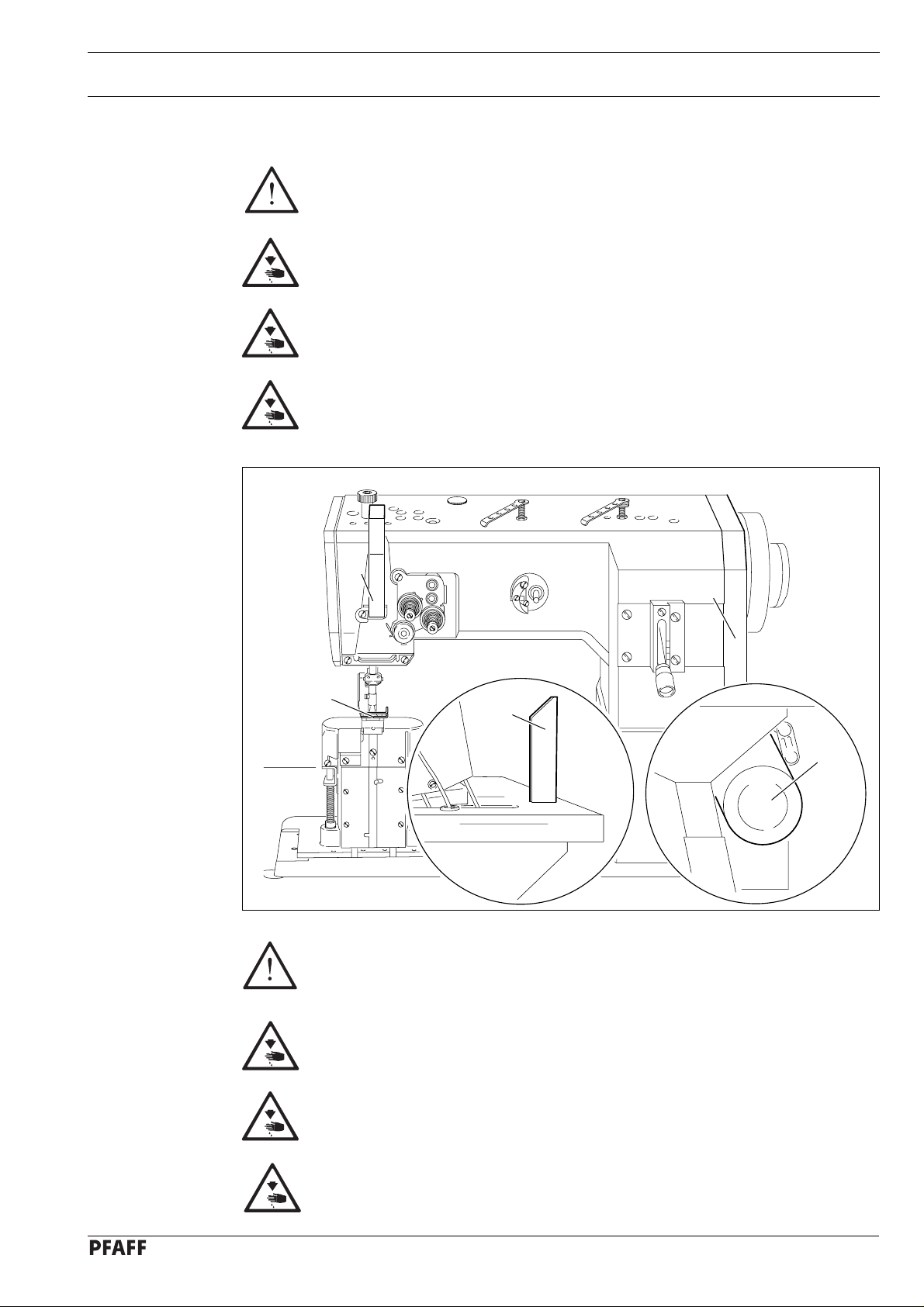
1.06 Danger warnings
A working area of 1 m must be kept free both in front of and behind the
machine, so that easy access is possible at all times.
Never put your hands or fingers in the sewing area during sewing!
Danger of injury by the needle!
While setting or adjusting the machine do not leave any objects on the table
nor in the needle plate area! Objects may be trapped or flung out of the
machine!
When a mechanically operated clutch motor without actuation lock is switched
off, alwys wait until the motor has stopped! Danger of injury!
Safety
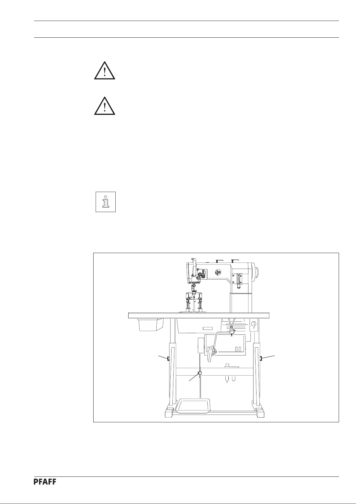
Fig. 1 - 01
2
3
1
Do not run the machine without support 1.
Danger due to top-heavy sewing head!
Machine may tip over backwards when tilted!
4
0
1
2
3
5
Do not run the machine without take-up lever guard 2!
Danger of injury by moving take-up lever!
Do not run the machine without finger guard 3!
Danger of injury by up and down movement of needle!
Do not run the machine without belt guards 4 and 5!
Danger of injury by rotating v-belt!
1 - 4

Proper use
2 Proper use
The PFAFF 1295 is a single-needle lockstitch postbed sewing machine with unison feed and
large vertical sewing hook.
The PFAFF 1296 is a two-needle lockstitch postbed sewing machine with unison feed and
large vertical sewing hooks.
These machines are for sewing lockstitch seams in the textile industry.
Any use of this machine which is not approved by the manufacturer shall be
considered as improper use! The manufacturere shall not be held liable for any
damage arising out of improper use! Proper use shall also be considered to
include compliance with the operation, adjustment, service and repair
measures specified by the manufacturer!
2 - 1

3 Specifications
Specifications
3.01 PFAFF 1295, PFAFF 1296
Stitch type:.................................................................................................. 301 (lockstitch)
Needle system....................................................................................................... 134 - 35
Needle size in 1/100 mm:
Version B : ............................................................................................................. 80 - 100
Versiong CN : ....................................................................................................... 110 - 140
▲
Max. thread size (synthetic
Version B : ................................................................................................................... 40/3
Version CN :................................................................................................................. 20/3
Max. stitch length:
Version BN :............................................................................................................ 6,0 mm
Version CN :............................................................................................................ 6,0 mm
Effective dia. of balance wheel: ............................................................................... 90 mm
Dimensions of the machine:
Length:...................................................................................................... approx. 530 mm
Breadth:: ................................................................................................... approx. 177 mm
Height (above table): ................................................................................. approx. 440 mm
):
◆
Clear workspace length: ........................................................................................ 265 mm
Clear workspace height: ........................................................................................ 115 mm
Fabric clearance (with presser foot raised): ............................................................. 14 mm
Postbed height:...................................................................................................... 165 mm
Net weight (sewing head):..........................................................................................55 kg
Mains voltage:...................................................................see instruction manual of motor
Max. power input:.............................................................see instruction manual of motor
Power supply fuse: ...........................................................see instruction manual of motor
Working pressure:....................................................................................................... 6 bar
Air consumption:............................................................................. ~0,8 l litres/work cycle
Ambient noise level:
Workplace noise level, PFAFF 1295, at a speed of 1,600 r.p.m.............................77 dB(A)
Workplace noise level, PFAFF 1296, at a speed of 1,500 r.p.m.............................76 dB(A)
Noise measurement according to DIN 45 635-48-A-1
◆
Subject to technical alterations
▲
Or comparable sizes of other thread types
3 - 1
Specifications
3.02 Possible versions and subclasses
Version B (only on 1296): ..................................................... For sewing medium materials
Version CN:................................................................ For sewing medium-heavy materials
Work aids:
Subclass -900/56.........................................................................................Thread trimmer
Subclass -911/97................................Automatic presser foot lift with backtacking system
3.03 Maximum speeds of the PFAFF 1295
Top feed stroke
Up to 5.5 mm
over 5.5 mm to 7 mm
Version
3.04 Maximum speeds of the PFAFF 1296
Top feed stroke
up 5.5 mm
Needle gauge
up 10 mm
Max. speed (s.p.m.)
B
C
B
C
Version
B
C
2200
1900
1800
1800
Max. speed (s.p.m.)
2100
1800
3 - 2
over 5.5 mm
from 10.4 mm
up 10 mm
from 10.4 mm
B
C
B
C
B
C
1900
1600
1800
1600
1500
1400

4 Disposal of the machine
● Proper disposal of the machine is the responsibility of the user.
● The materials used for the machine are steel, aluminium, brass and various plastics.
The electrical equipment comprises plastic materials and copper.
● The machine must be disposed of according to the locally valid pollution control
regulations; if necessary, a specialist will have to be contracted.
Care must be taken that parts soiled with lubricants are disposed of separately
according to the locally valid pollution control regulations!
Disposal of machine waste
4 - 1

Transportation, packing and storage
5 Transportation, packing and storage
5.01 Transportation to the customer’s premises
Within the Federal Republic of Germany, complete machines (with table and motor) are
delivered without packing.
Machines without table (sewing heads only) and machines intended for exports are packed.
5.02 Tansportation inside the customer’s premises
The manufacturer cannot be made liable for transportation inside the customer’s premises
nor to other operating locations. Care must be taken that the machines are only transported
in an upright condition.
5.03 Disposal of packing materials
The packing materials of this machine comprise paper, cardboard and VCE fibre. Proper
disposal of the packing material is the responsibility of the customer.
5.04 Storage
If the machine is not in use, it can be stored as it is for a period of up to six months, but
after that it should be protected against dust and moisture.
If the machine is stored for longer periods, the individual parts, especially the surfaces of
moving parts, must be protected against corrosion, e.g. by a film of oil.
5 - 1

6 Explanation of symbols
In this instruction manual, work to be carried out, or important information, is accentuated
by symbols. These symbols have the following meanings:
Note, information
Cleaning, care
Lubrication
Explanation of symbols
Maintenance, repairs, adjustment, service work
(only to be carried out by technical staff)
6 - 1
Controls
7 Controls
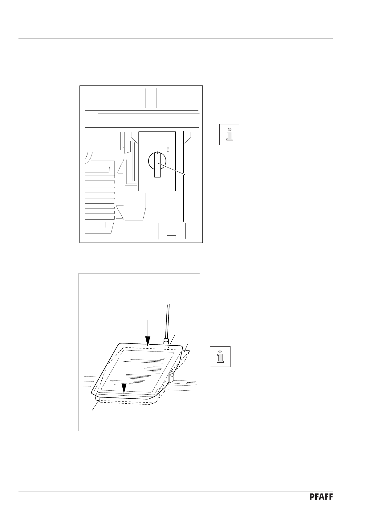
7.01 On/off switch
● The power supply to the machine is
switched on or off by turning switch 1.
The illustrated on/off switch is
fitted to machines with Quick
motors. If other motors are
O
used, a different switch may
be fitted.
1
Fig. 7 - 01
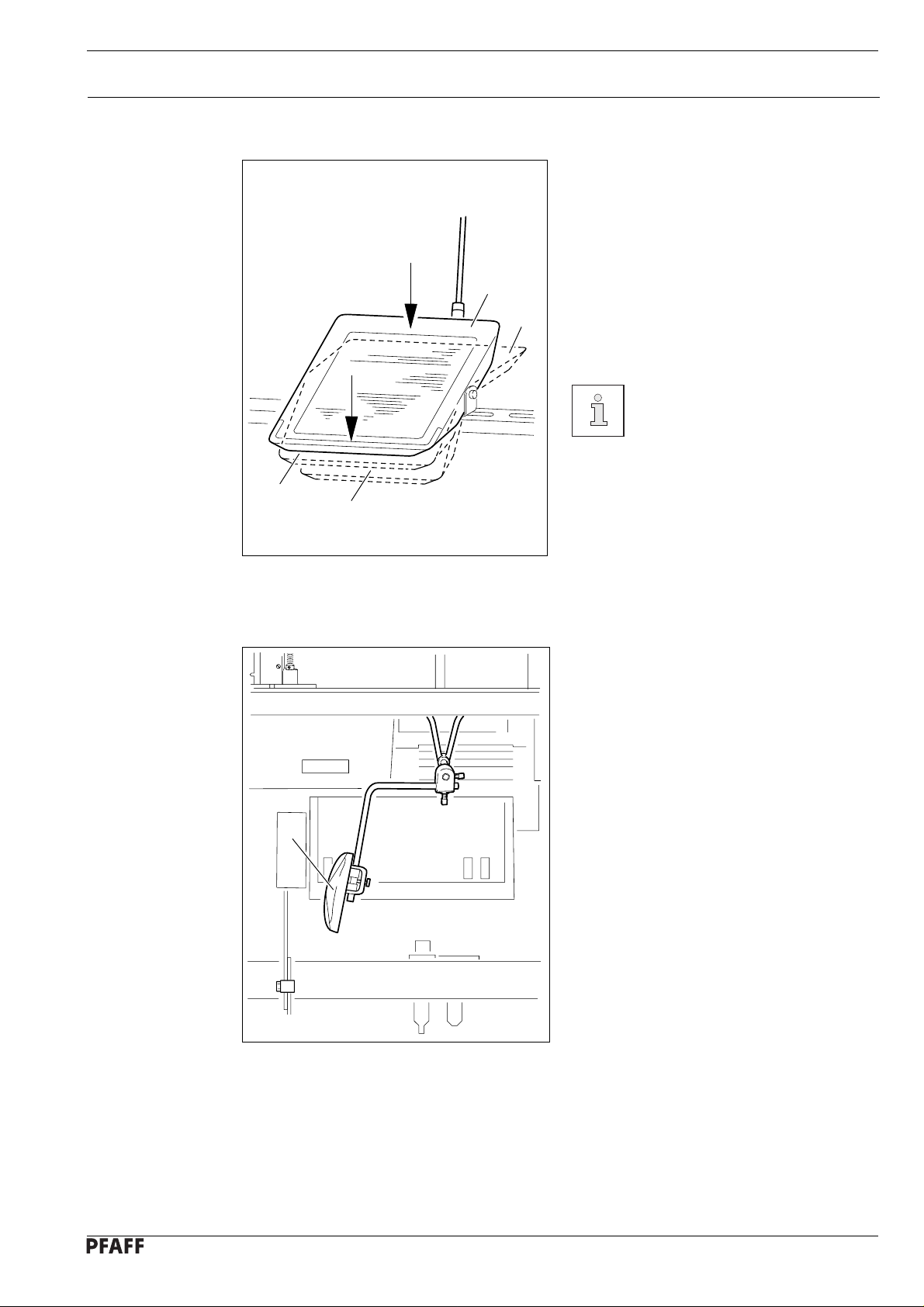
7.02 Pedal (on machines without subclass -911/97)
0 = Neutral position
+1 = Sewing
-1 = Thread trimming (on machines with
0
+1
-1
thread trimmer)
For further pedal functions
please refer to the instruction
manual of the motor
manufacturer.
7 - 1
Fig. 7 - 02
7.03 Pedal (on machines with subclass -911/97)
0 = Neutral position
+1 = Sewing
-1 = Raise presser foot
0
Controls
+1
-2 = Thread trimming (on machines with
thread trimmer)
-1
-2
Fig. 7 - 03
7.04 Knee lever (on machines without subclass -911/97)
● The presesr foot is raised by pressing
knee lever 1.
For further pedal functions
please refer to the instruction
manual of the motor
manufacturer.
1
Fig. 7 - 04
7 - 2
Controls
7.05 Key on machine head (on machines with subclass -911/97)
● If key 1 is pressed during sewing, the
machine will switch to reverse sewing.
1
Fig. 7 - 05
7.06 Presser bar lifter
1
● The presser foot is lifted by raising
presser bar lifter 1.
7 - 3
Fig. 7 - 06
7.07 Feed regulator/reverse sewing
0
1
2
3
Controls
● The stitch length is adjusted by turning
the knurled nut on lever 1.
● To reverse the sewing direction press
lever 1 fully upwards.
1
Fig. 7 - 07
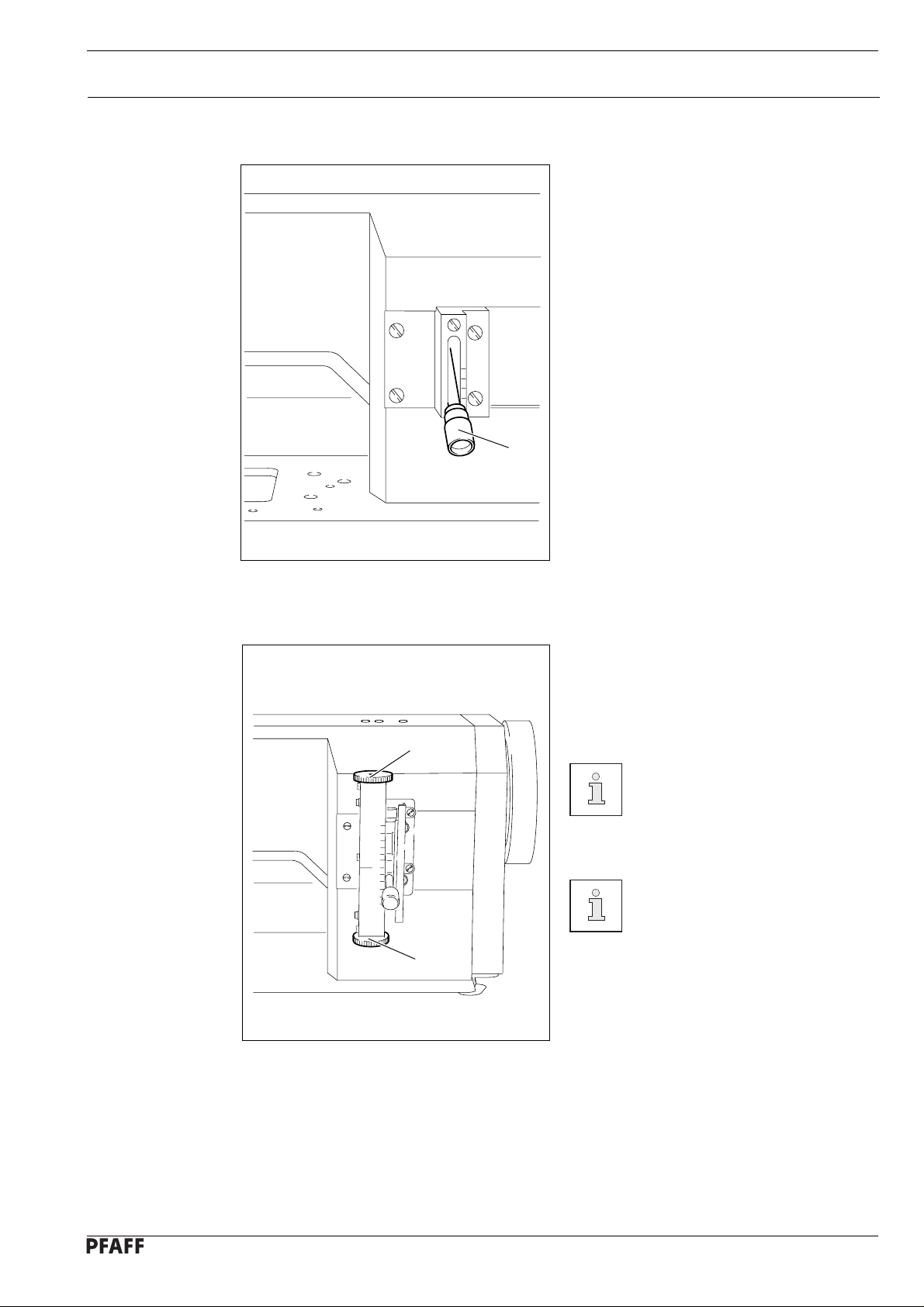
7.08 Feed regulator (on machines with subclass -911/97)
● Turn knurled screw 1 to adjust the stitch
length for sewing forwards.
● Turn knurled screw 2 to adjust the stitch
length for sewing backwards.
2
Reverse stitches can be set as
long as required, independently
of forward stitches.
For adjustment of automatic
start- and finish backtacks
please refer to the instruction
book of the motor
1
manufacturer.
Fig. 7 - 08
7 - 4
Controls
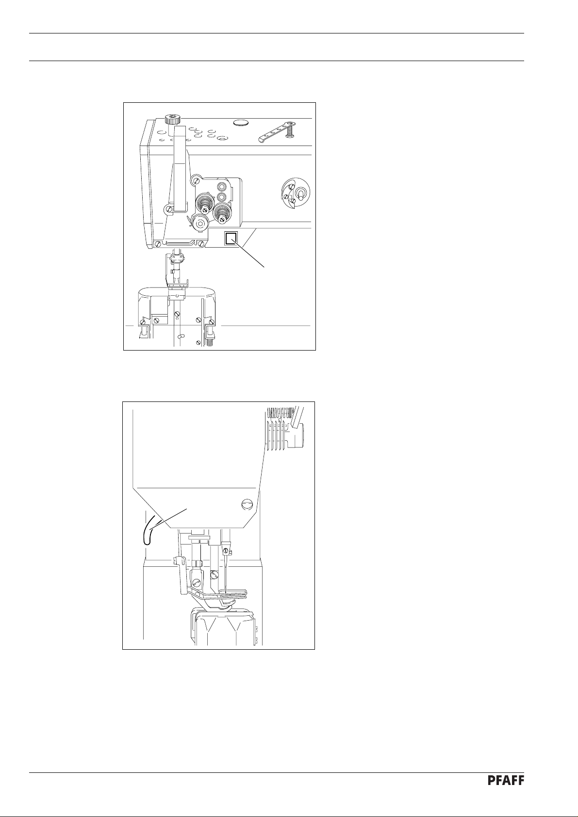
7.09 Adjusting nut for the top feed stroke
Switch off the machine!
2
● Loosen screw 1 at the back of the
machine.
● Open cover 2.
● Loosen screw 3 and adjust lever
3
-
+
1
accordingly.
● Close cover 2 and tighten screw 1.
Fig. 7 - 09
7 - 5
8 Installation and commissioning
The machine must only be installed and commissioned by qualified personnel!
All relevant safety regulations must be strictly adhered to!
If the machine is delivered without a table, be sure to use a stand and table
that will reliably support the weight of the machine with its motor.
It is very important to ensure that the stand of the machine is firm and steady,
also during sewing.
8.01 Installation
The site where the machine is installed must be provided with suitable connections for
electric current and compressed air. It must be ensured that the standing surface of the
machine site is firm and horizontal and that sufficient lighting is available.
For packing and transportation reasons the table top is in the lowered position.
The table height is adjusted as described below.
Installation and commissioning
8.01.01 Adjusting the table height
1
1
2
Fig. 8 - 01
● Loosen screws 1 and 2 and set the table at the required height.
● Fully tighten screw 1.
● Set the required pedal position and tighten tighten screw 2.
8 - 1

Installation and commissioning
8.01.02 Tensioning the v-belt
2 cm
1
● Loosen nuts 1.
● Tension v-belt by adjusting bracket 2.
● Tighten nuts 1.
Fig. 8-02 shows a Quick motor.
If a different motor is used,
please refer to the instruction
manual of the motor
manufacturer.
2
Fig. 8 - 02
8.01.03 Fitting the upper belt guard
6
4
2
5
6
8
4
If a large balance wheel is in
use, break off corner 1 of belt
guard part 3.
● Screw stop piece 2 onto belt guard part 3.
● Screw on belt guard part 3 with screws 4.
3
8
7
● Screw on belt guard part 5 with screws 6.
● Secure belt guard part 7 to the table top
using woodscrews 8.
8
8 - 2
Fig. 8 - 03

8.01.04 Fitting the lower belt guard
Installation and commissioning
● Position belt guard 1 so that motor pulley
and v-belt can run freely.
Fig. 8-04 shows a Quick
motor. If a different motor is
used, please refer to the
instruction manual of the motor
manufacturer.
1
Fig. 8 - 04
8.01.05 Fitting the synchroniser
2
● Push synchroniser 1 onto the shaft.
● Tighten screws 2 a little.
● Connect the synchroniser plug at the
control box.
● Adjust the synchroniser (see Chapter
11.05.14, Adjusting the synchroniser).
1
Fig. 8 - 05
8 - 3

Installation and commissioning
8.01.06 Assembling the reel stand
● Assemble the reel stand as shown in
Fig. 8-06.
● Afterwards insert the stand in the hole in
the table top and secure it with the nuts
provided.
Fig. 8 - 06
8.02 Commissioning
● Check the machine, particularly its electrical wiring and pneumatic tube connections, for
any damage.
● Clean the machine thoroughly and afterwards fill it with oil and oil the machine (see
Chapter 10, Care and maintenance).
● Have a mechanic check whether the motor of the machine can be used with the
available power supply and that the motor is correctly connected to the junction box. Do
not run the machine if there is any discrepancy.
● When the machine is running, the balance wheel must turn towards the operator. If it
does not, have the motor connection changed by a mechanic.
● Connect the machine to the compressed air supply. When it is connected, the gauge
should show a pressure of approx. 6 bar. If necessary, have this reading correctly set
(see Chapter 10.06, Checking/adjusting the air pressure).
8.03 Switching the machine on/off
8 - 4
● Switch the machine on/off (see Chapter 7.01, On/off switch).
● Carry out a running test.

9 Setting up
All instructions and regulations in this manual must be observed. Special
attention must be given to all safety regulations!
All setting-up work must only be done by personnel with the necessary
training. For all setting-up work the machine must be isolated from the power
supply by turning off the on/off switch or removing the machine plug from the
electric power socket!
9.01 Inserting the needle on the PFAFF 1295
Setting up
Switch off the machine!
Danger of injury due to
unintentional starting of the
machine!
Fig. 9 - 01
Only use needles of system 134-35.
● Set needle bar at top position and loosen
screw 1.
● Push needle 2 fully in (the long needle
groove must face to the left).
● Tighten screw 1 again..
1
2
The choice of needle depends on the version of the machine and the sewing
thread and material in use (see Chapter 3, Specifications).
9 - 1

Setting up
9.02 Inserting the needles on the PFAFF 1296
Switch off the machine!
Danger of injury due to
unintentional starting of the
machine!
Only use needles of system 134-35.
● Set needle bar at top position and loosen
screws 1.
● Push needles 2 fully in (the long groove
of the left needle must face to the right
and that of the right needle to the left).
● Tighten screws 1 again.
1
Fig. 9 - 02
2
The choice of needle depends on the version of the machine and the sewing
thread and material in use (see Chapter 3, Specifications).
9 - 2

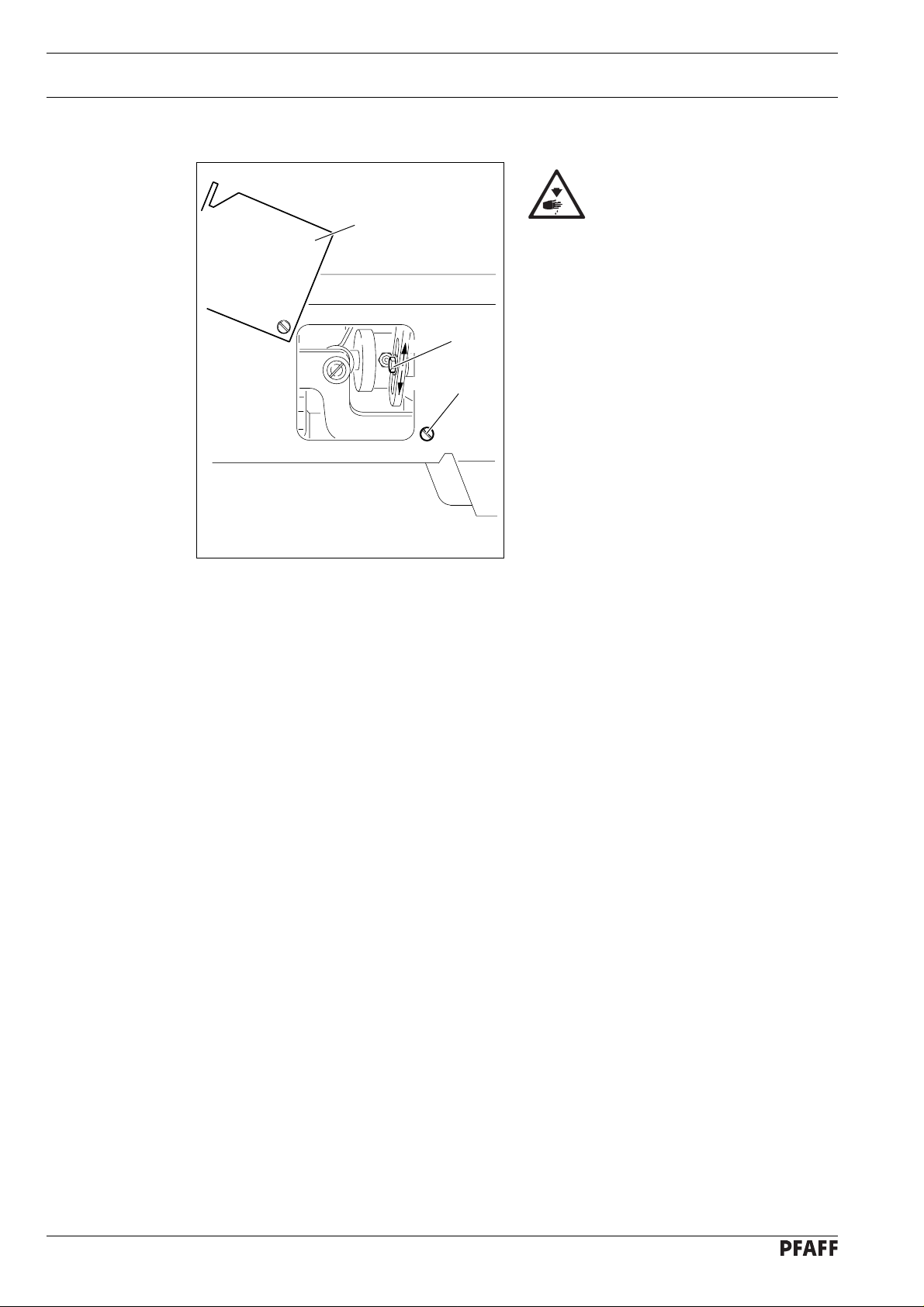
9.03 Winding the bobbin thread, regulating the winder tension
4
Setting up
-
+
6
1
3
5
2
Fig. 9 - 03
● Place an empty bobbin 1 on winder spindle 1.
● Thread up as shown in Fig. 9-03 and wind the thread a few ttimes clockwise around
bobbin 1.
● Engage the bobbin winder by pressing spindle 2 and lever 3 simultaneously
The bobbin is wound during sewing.
● The tension of the thread wound onto bobbin 1 is set on knurled screw 4.
● The bobbin winder will stop when sufficient thread is wound onto bobbin 1.
If the thread is wound on unevenly:
● Loosen nut 5.
● Turn thread guide 6 as required.
● Tighten nut 5 again.
9 - 3

Setting up
9.04 Changing the bobbin
Switch off the machine!
Danger of injury due to
unintentional starting of the
machine!
2
Removing the bobbin case:
● Set the take-up lever at its highest point.
● Remove the post cover, lift latch 1 and
1
take out bobbin case 2.
Inserting the bobbin case:
● Insert bobbin case 2 so that you feel it
snap in place.
● Push latch 1 down and close the post
cover.
Fig. 9 - 04
Do not run the machine with the post cover open!
Danger of injury by moving parts!
9.05 Threading the bobbin thread and regulating the bobbin thread tension
Switch off the machine!
Danger of injury due to
unintentional starting of the
machine!
5 cm
● Thread the bobbin as shown in Fig. 9-05.
● When the thread is pulled, the bobbin
must rotate as shown by the arrow.
● Regulate the bobbin thread tension on
srew 1.
9 - 4
Fig. 9 - 05
+
1
-

Setting up
9.06 Threading needle thread/adjusting needle thread tension on the PFAFF 1295
1
Fig. 9 - 06
Switch off the machine!
Danger of injury due to unintentional starting of the machine!
● Thread needle thread as shown in Fig. 9-06. Be sure to thread the needle from the left.
● Regulate the needle thread tension by turning knurled screw 1.
9 - 5

Setting up
9.07 Threading needle thread/adjusting needle thread tension on the PFAFF 1296
2
1
9 - 6
Fig. 9 - 07
Switch off the machine!
Danger of injury due to unintentional starting of the machine!
● Thread needle threads as shown in Fig. 9-07. Be sure to thread the right needle from
the left and the left needle from the right.
● Regulate the needle thread tensions by turning knurled screw 1 (right needle) or 2 (left
needle).

10 Care and maintenance
Check air pressure ........................................................ daily, each time before operation
Clean hook area ............................................ daily, in continuous operation several times
Check water bowl of air filter/regulator.......................................... daily, before operation
Oil hook...................................................................................................................... daily
General oiling ............................................................................................... twice a week
Oil needle-head parts ................................................................................... twice a week
Clean hook .................................................................................................... once a week
Lubricate top-feed drive eccentric ................................................................ once a week
The maintenance intervals in the table refer to the average machine running
time in single-shift operation. If the machine running time is longer than this, it
is advisable to shorten these intervals.
Care and maintenance
10.01 Cleaning
Fig. 10 - 01
Switch off the machine!
Danger of injury due to
3
5 mm
2
1
● Clean hook area with a brush daily, in
continuous operation several times daily.
● Clean the hook thoroughly once a week.
● Open post cover.
● Set needle bar at its highest position.
● Remove top of bobbin case together
with bobbin
● Unscrew and remove hook gib 1.
● Turn balance wheel until point of bobbin
case 2 has entered into the groove of the
hook race by about 5 mm.
● In this position remove bobbin case 2.
● Clean hook race with petroleum spirit.
unintentional starting of the
machine!
● When inserting the bobbin case, make sure that bobbin case position finger 3 enters the
slot in the needle plate.
● Screw on hook gib 1.
● Insert bobbin case and close post cover.
10 - 1

Care and maintenance
1
2
3
0
10.02 General oiling
10 - 2
Fig. 10 - 02
● Apply oil at all bearing points above the table (see arrows) twice a week.
Switch off machine! Danger of injury!
● Pull knee lever out to the front and tilt machine backwards.
● Apply oil at all bearing points beneath the table (see arrows) twice a week.
Set the machine upright with both hands! Danger of crushing between sewing
head and table!

Care and maintenance
Only use oil with a medium viscosity of 22.0 mm²/s at 40° C and a density of
0.865 g/cm³ at 15°C!
We recommend PFAFF sewing-machine oil, part No. 280-1-120 144.
10.03 Oiling the sewing hook
Fig. 10 - 03
1
Switch off the machine!
Danger of injury due to
unintentional starting of the
machine!
● Open the post cover.
● Set the needle bar at its highest position.
● Apply 1 or 2 drops of oil in hole 1 of the
hook gib.
● Apply a few drops of oil to the hook race
(see arrow)
Only use oil with a medium
viscosity of 22.0 mm²/s at 40°
C and a density of 0.865 g/cm³
at 15°C!
We recommend PFAFF
sewing-machine oil, part
No. 280-1-120144.
10 - 3

Care and maintenance
10.04 Oiling the needle-head parts
Fig. 10 - 04
Switch off the machine!
Danger of injury due to
unintentional starting of the
machine!
● Remove the faceplate.
● Oil all moving parts and bearing points
(see arrows) twice a week.
● Refit the faceplate.
Only use oil with a medium
viscosity of 22.0 mm²/s at 40°
C and a density of 0.865 g/cm³
at 15°C!
We recommend PFAFF
sewing-machine oil, part
No. 280-1-120144.
10.05 Lubricating the top-feed drive eccentric
2
● Loosen screw 1 and open cover 2 on the
● Apply a little grease at nipple 3 at least
● Close cover 2 and tighten screw 1.
1
3
Fig. 10 - 05
Switch off the machine!
Danger of injury due to
unintentional starting of the
machine!
rear side of the machine.
once a year.
Only use lithium grease with a
dripping point of 185°C and a
roll-penetration of 22 to 25 mm
at 25°C.
We recommend PFAFF sewing
machine grease, part
No. 280-1-120247.
10 - 4

10.06 Checking/regulating the air pressure
2
8
6
4
2
0
10
100
150
50
0
12
200
14
230
16
1
Care and maintenance
● Check the air pressure on gauge 1 every
time before operation.
● Gauge 1 must show a pressure of 6 bar.
● Regulate this pressure if required.
To do so, pull knob 2 up and turn it
accordingly.
Fig. 10 - 06
10.07 Emptying/cleaning the water bowl of the air filter/regulator
Switch off the machine.
Disconnect the air hose at the
air filter/regulating unit.
Emptying the water bowl
8
50
0
max.
10
100
150
12
200
14
230
16
2
6
4
2
0
1
● Water bowl 1 empties itself
automatically when the air hose is
disconnected from the air filter/regulator.
Cleaning the filter
● Unscrew water bowl 1 and take out filter
2.
● Clean the filter with compressed air or
with isopropyl-alcohol, part number
95-665735-91.
● Screw in filter 2 and screw on water bowl 1.
10.07
Fig. 10 - 07
10 - 5

Adjustment
11 Adjustment
11.01 Tools, gauges and other equipment for adjusting
For the adjustments in this chapter the PFAFF 1296 two-needle machine is
illustrated. On the PFAFF 1295 single-needle machines various adjustments
only have to be carried out on one side, i.e. in the right-hand hook area. This is
referred to in the different chapters.
● Screwdrivers withi blade widths from 2 to 10 mm
● Spanners (wrenches) in sizes from 7 to 14 mm
● Allen keys from 2 to 6 mm
● Metal rule (part No. 08-880218-00)
● Needle-rise gauge (part No. 61-111600-01)
● Screw clamp (part No. 61-111600-35/001)
● Needles, system 134-35
● Sewing thread and material for stitching off
11.02 Notes on adjustment
All adjustments in this instruction manual refer to a completely assembled machine and
must only be carried out by appropriately trained technical personnel. Machine covers that
have to be removed and replaced for checks and adjustment work are not mentioned in the
text.
The screws and nuts indicated in brackets () are for the fixation of machine parts that have
to be unscrewed before adjustment and tightened again afterwards.
11.03 Abbreviations
t.d.c. = top dead centre
b.d.c. = bottom dead centre
11 - 1

Adjustment
11.04 Adjusting the basic machine
11.04.01 Position of the bottom feed dog crosswise to sewing direction
Requirement
The bottom feed dog must be the same distance from the left and right side of the feed slots.
4
Fig. 11 - 01
1
X
X
3
2
4
1
● Loosen screws 1 and 2.
● Position rock shaft 3 according to Requirement..
● Tighten screw 1.
The flats of pins 4 must face screws 1 and rock shaft 3 must neither have any
play nor bind.
Leave screws 2 loose for the following adjustments.
11 - 2

Adjustment
11.04.02 Adjusting the bottom feed dog in sewing direction
Requirement
With the longest stitch length set, the bottom feed dog must not strike the feed slot at the
front or rear end of its stroke.
1
Fig. 11 - 02
● Set the longest stitch length.
● Turn rock shaft 1 according to Requirement. and tighten screws 2.
2
11 - 3

11.04.03 Bottom feed dog height
Requirement
With the stitch length set at "0" the feed dog must protrude from the needle plate by the
height of its teeth when at its highest position.
tooth height
Adjustment
2
1
Fig. 11 - 03
● Set stitch length „0“.
● Turn the balance wheel to set the bottom feed dog at its highest position.
● Adjust bracket 1 (screws 2) according to Requirement.
On machines without bottom-feed lifting phase (without "P") the feed dog
height may be reduced somewhat if necessary.
11 - 4

Adjustment
11.04.04 Needle height (preliminary adjustment)
Requirement
With the needle bar at b.d.c. the clearance between needle bar and needle plate must be
15 mm.
2
1
Fig. 11 - 04
● Re-position the height of needle bar 1 (screws 2) according to Requirement, but do not
turn it.
1
15 mm
11 - 5

1
2
3
0
11.04.05 Needle in needle-hole centre
Requirement
With the stitch length set at "0" the needle must enter exactly in the centre of the needle
hole.
Adjustment
4
3
7
5
6
8
9
1
2
Fig. 11 - 05
● Remove vibrating presser 1 and lifting presser 2.
● Set the stitch length at "0" and set the needle bar at t.d.c.
● Insert a new needle, loosen screws 3, 4, 5 and 6.
● Turn the balance wheel to set the needle immediately above the bottom feed dog.
● Shift the position of needle bar frame 7 according to Requirement.
● Tighten screws 3, 4 and 5.
● Move stop 8 up against needle bar frame 7 and tighten screw 6.
There must be no binding of needle bar frame 7 in guide 9 nor in the top-feed
drive linkages.
11 - 6

Adjustment
11.04.06 Bottom feed dog lifting motion
Requirement
1. With the needle bar at b.d.c. the feed dog must be at its highest position.
2. When the longest stitch length is set and the balance wheel is turned, the bottom feed
dog must reach the top side of the needle plate at the same time as the needle.
1
2
11 - 7
Fig. 11 - 06
This adjustment does not apply to machines without bottom-feed dog lifting
phase (without "P")
● Set needle bar at b.d.c.
● Turn eccentric 1 (screws 2) according to Requirement 1.
● In this position tighten the accessible screw 2 just enough to allow eccentric 1 to be
turned against a resistance.
● Turn eccentric 1 slightly according to Requirement 2.
● Tighten both screws 2.

11.04.07 Feeding stroke of bottom and top feeds
Requirement
With the longest stitch length set and the needle bar at b.d.c. neither the top- nor bottom
feed must make any movement when the reverse-feed lever is operated.
Adjustment
2
1
Fig. 11 - 07
● Set the longest stitch length.
● Undo screw 1 enough to allow eccentric 2 to be turned on the shaft against a resistance.
● Set needle bar at b.d.c.
● First turn eccentric 2 so that its highest eccentric point is facing "downwards."
● Now turn it slightly in rotation direction according to Requirement.
● Tighten screw 1.
11 - 8

Adjustment
11.04.08 Hook clearance, needle rise, needle height and needle guard
Requirement
With the stitch length set at "3" and in needle-rise position (= 1.8 mm past b.d.c. on version
"B" or 2.0 mm past b.d.c. on version "C")
1. The hook point must be at the "needle centre" and the clearance between hook and
needle 0.05 to 0.1 mm,
2. the top end of the needle eye must be 0.8 to 0.1 mm below the hook point, and
3. needle guard 8 must touch the needle just lightly.
0.05 - 0.1 mm
1
8
6
2
7
3
6
23
1
7
1
1
4
5
0.8 - 1 mm
11 - 9
Fig. 11 - 08
● Set the stitch length at "3" and loosen screws 1, 2 and 3.
● Loosen screws 4 at the front and rear side.
● Position posts 5 according to Requirement 1.
● Tighten screws 1 and 4.
● Set the needle bar at b.d.c. and place the 1.8 or 2.0 mm thick feeler gauge close under
the needle bar bearing, move the screw clamp up against the feeler gauge and screw it
tight.
● Remove the feeler gauge and turn the balance wheel in sewing direction until the screw
clamp is against the needle bar bearing.

Adjustment
● Set the hook point at the needle centre, making sure that the needle is not deflected by
needle guard 8.
● Making sure that bevel gear 6 is not too close, but the hook has not too much play,
tighten screws 2.
● Move fixing collar 7 up against bevel gear 6 and tighten screws 3.
● Adjust the needle height according to Requirement 2 (see also Chapter 11.04.04,
Needle height preliminary adjustment).
● position needle guard 8 according to Requirement 3.
After changing the needle clearance be sure to readjust the connecting linkage
of the thread trimmer mechanism (see also Chapter 11.05.6, Connecting
linkage).
11 - 10

Adjustment
11.04.09 Top feed stroke
Requirement
With the longest top feed stroke set and the stitch length at "0", lifting presser 1 and
vibrating presser 2 must each rise from the needle plate by 7.0 mm when the balance
wheel is turned.
4
3
7 mm
2
1
7 mm
Fig. 11 - 09
● Set the longest top feed stroke and stitch length "0".
● Lower lifting presser 1.
● Turn the balance wheel in sewing direction until vibrating presser 2 has reached its
highest point.
● Turn crank 3 (srews 4) according to Requirement.
11 - 11

11.04.10 Top feed lifting motion
Requirement
When lifting presser 1 is resting on the needle plate, vibrating presser 4 and needle point 5
must reach the needle plate at the same time at the highest top feed stroke.
Adjustment
2
3
5
1
4
Fig. 11 - 10
● Lower lifting presser 1 onto the needle plate.
● Loosen screws 2 just enough to allow eccentric 3 to be turned against a resistance on it
shaft.
● Turn eccentric 3 according to Requirement.
● Tighten screws 2.
11 - 12

Adjustment
11.04.11 Bobbin case opener
Requirement
The needle thread must neither be trapped between bobbin case opener 3 and hook base
4 nor between position finger 5 and the retainer on the needle plate (see arrows).
2
6
5
1
3
4
Fig. 11 - 11
● Undscrew and remove post covers 1 (on left post from the rear).
● Undo screws 2 enough to allow bobbin case opener 3 to be turned on its shaft against a
resistance.
● Thread up the machine, place sewing material in and lower the lifting presser.
● Set bobbin case opener 3 according to Requirement.
● In this position, apply pressure on the bobbin case opener from the top, move clamp
collar 6 up against it and tighten screws 2.
11 - 13

11.04.12 Slip coupling
Slip coupling 4 is adjusted at the works. When a thread jams, slip coupling 4
disengages, in order to avoid damage to the hooks. To engage the coupling
again, proceed as follows.
Adjustment
1
4
2
3
4
Fig. 11 - 12
● Remove jammed thread.
● Press plunger 1 and turn the balance wheel until pawl 2 engages groove 3.
11 - 14

Adjustment
11.04.13 Needle-thread tension release
Requirement
With the lifting presser raised, there must be a clearance of at least 0.5 mm between
tension discs 4.
2
0.5 mm
1
3
4
Fig. 11 - 13
● Position pressure plate 1 behind mounting bracket 2 according to Requirement.
The clearance of 0.5 mm is a miminum setting and may be as much as 1 mm
for heavy threads.
When the tension is engaged, release pin 3 must not be under load.
11 - 15

11.04.14 Thread check spring, without subclass -900/56
Requirement
The movement of thread check spring 5 must be finished when the needle pointe enters
the material (=spring stroke of about 7 mm).
Adjustment
7 mm
5
1
3
2
Fig. 11 - 14
● Adjust stop 1 (screw 2) according to Requirement.
● To adjust the pressure of the spring, turn screw 3 (screw 4).
For technical reasons the length of the thread check spring stroke may vary
upwards or downwards a little.
4
11 - 16

Adjustment
11.04.15 Thread check spring on the PFAFF 1296 with subclass -900/56
Requirement
The movements of thread check springs 1 and 6 must be finished when the needle points
enter the material (=spring stroke of about 7 mm).
Fig. 11 - 15
810
5
1
6
7 mm
4
2
7
9
3
11 - 17
● To adjust the pressure of spring 1, turn screw 2 (screw 3).
● Adjust stop 4 (screw 5) according to Requirement.
● To adjust the pressure of spring 6, turn screw 7 (screw 8).
● Adjust stop 9 (screw 10) according to Requirement.
For technical reasons the length of the thread check spring stroke may vary
upwards or downwards a little.

11.04.16 Bobbin winder
Requirement
1. With the bobbin winder engaged, drive wheel 1 must be driven reliably .
2. With the bobbin winder disengaged, friction wheel 5 must not run against drive wheel 1.
3. The bobbind winder must switch itself off when the filled thread is about 1 mm from
the rim of the bobbin.
Adjustment
1
Fig. 11 - 16
2
4
5
1 mm
3
● Re-position drive wheel 1 (screws 2) according to Requirements 1 and 2.
● Re-position pin 3 (screw 4) according to Requirement 3.
11 - 18

Adjustment
11.04.17 Pressure of the lifting presser
Requirement
1. The material must be properly fed, even at the highest sewing speed.
2. There must be no pressure marks on the material.
1
11 - 19
Fig. 11 - 17
● Turn screw 1 according to the Requirement.

11.05 Adjusting the thread trimmer -900/56
11.05.01 Engaging solenoid
Requirement
1. Mounting bracket 1 must be in the middle of its adjusting range and parallel with the
right-hand edge of the mounting bracket.
2. When the thread trimmer is in its resting position the core of solenoid 3 must protrude
from the solenoid housing by about 4 mm.
4 mm
Adjustment
4
3
1
2
Fig. 11 - 18
● Re-position bracket 1 (screw 2) according to Requirement 1.
● Re-position solenoid 3 (screw 4) according to Requirement 2.
11 - 20

Adjustment
11.05.02 Control cam (preliminary adjustment)
Requirement
1. Control cam 1, must be centred with the cutout of bearing mounting 5.
2. With the needle bar at t.d.c., screws 2 must be visible from the front and aligined
parallel with the bedplate.
2
4
4
3
3
1
5
Fig. 11 - 19
● Re-position control cam 1 (screws 2) and fixing collars 3 (screws 4) according to
Requirement.
11 - 21

11.05.03 Control lever spring action
Requirement
When the thread trimmer is in its resting position, it must be possible to press control lever 3
about 1 mm towards the bedplate (spring action).
Adjustment
2
3
1
Fig. 11 - 20
● Turn screw 1 (nut 2) according to Requirement.
11 - 22

Adjustment
11.05.04 Control lever stroke
Requirement
1. When engaging lever 5 is operated the pin of control lever 6 must drop freely into the
track of control cam 7.
2. After thread trimming, control lever 6 must pass freely on the right side of stop plate 3
and engage control lever 5 behind stop plate 3.
3. There must be a clearance of 0.2 mm between the pin of control cam 6 and the righthand inside of the control cam track.
0.2 mm
4
5
2
3
6
1
7
Fig. 11 - 21
● Re-position stop plate 1 (screws 2) and stop plate 3 (screws 4) according to
Requirement.
11 - 23

11.05.05 Thread-trimmer drive linkage
Requirement
1. On the PF AFF 1296 thread-catcher drive linkage 1 must have a length of 128 mm, less
half of the needle gauge.
On the PF AFF 1295, thread catcher drive linkage 1 must have a length of 128 mm
2. When the threa trimmer is in its resting position there must be a clearance of about
1 mm between plunger 5 and lever 6.
128 mm
Adjustment
6
Fig. 11 - 22
1 mm
2
1
2
4
3
5
● Turn thread-catcher drive linkage 1 (nuts 2) to adjust it according to Requirement 1.
● Re-position bracket 3 (screw 4) according to Requirement 2.
11 - 24

Adjustment
11.05.06 Linkage bar (only on the PFAFF 1296)
Requirement
The length of linkage bar 1 must be the same as the distance between the two threadcatcher drive shafts 3.
=
3
3
1
2
=
Fig. 11 - 23
● Adjust middle section 1 (nuts 2) of the linkage bar according to Requirement.
2
11 - 25

11.05.07 Thread catcher height
Requirement
There must be a clearance of 0.7 mm between the underside of thread catcher 4 and
bobbin case cap 5.
4
5
Adjustment
0.7 mm
4
2
Fig. 11 - 24
● Loosen screws 1 and 2.
● Adjust the height of shaft 3 according to Requirement.
● Tighten screws 1.
Leave screws 2 loose for the following adjustment.
3
1
11 - 26

Adjustment
11.05.08 Thread catcher resting position
Requirement
When the thread trimmer is in its resting poistion there must be a clearance of about 4
mm between the point of catcher 3 and the cutting edge of knife 4.
4 mm
3
3
4
1
2
11 - 27
Fig. 11 - 25
● Turn shaft 2 according to Requirement.
● Tighten screws 1.
When tightening screws 1 make sure that all transmission parts of the thread
catcher drive can move freely.

11.05.09 Knife pressure
Requirement
When the front edge of thread catcher 3 has passed the knife cutting edge by half, knife 1
must rest with light pressure on the edge of the catcher.
Adjustment
3
2
3
1
Fig. 11 - 26
● Adjust knife 1 (screws 2) according to Requirement
11 - 28

Adjustment
11.05.10 Bobbin thread trapping spring
Requirement
1. Bobbin thread trapping spring 3 must not be deflected by thread catcher 4 in any phase.
2. After the trimming action the bobbin thread must be securely trapped.
3. It must be possible to insert and remove the bobbin from the hook without any hindrance.
3
4
1
3
2
4
11 - 29
Fig. 11 - 27
● Re-position bracket 1 (screws 2) according to Requirements 1 and 3.
● Bend trapping spring 3 according to Requirement 2.

11.05.11 Control cam (final adjustment)
Requirement
The trimming action must be just completed when the take-up lever is at t.d.c.
Adjustment
2
Fig. 11 - 28
● Turn control cam 1 (screws 2) according to Requirement.
1
11 - 30

Adjustment
11.05.12 Release lever
Requirement
When the pin of control lever 3 has dropped into the track of control cam 4 and the needle
bar is at b.d.c. there must be a clearance of about 1 mm between control lever 3 and
release lever 5. In this position the needle thread tension must still be engaged.
4
5
3
1 mm
1
Fig. 11 - 29
● Turn eccentric 1 (screw 2) according to Requirement
2
11 - 31

11.05.13 Release rod
Requirement
1. When the lifting presser is resting on the needle plate, pin 3 must rest at the lower end
of the elongated hole in pull-rod 1.
2. The tension discs must not be moved apart in this position.
Adjustment
2
1
3
1
Fig. 11 - 30
● Re-position pull-rod 1 (screws 2) according to Requirement.
11 - 32

Adjustment
11.05.14 Adjusting the synchroniser
Requirement
1. When sewing is interrupted, the machine must position at about 4 mm past b.d.c. of
the needle bar.
2. After thread trimming the machine must position with the take-up lever at t.d.c.
● Carry out adjustment according to instruction manual of motor.
11 - 33

Notes

G.M. PFAFF
Aktiengesellschaft
Postfach 3020
D-67653 Kaiserslautern
Königstr. 154
D-67655Kaiserslautern
Telefon: (0631) 200-0
Telefax: (0631) 17202
Telex: 45753 PFAFF D
Gedruckt in der BRD
Printed in Germany
Imprimé en R.F.A.
Impreso en la R.F.A.
 Loading...