

Page 1

Visit RepairManualClub.com for more
motorcycle manuals
Buy Motorcycle Gear and
Equipment
Buy Helmets, Jackets, Pants
Buy Everything Motorcycle at
Amazon.com
Visit RepairManualClub.com for more
motorcycle manuals
Page 2
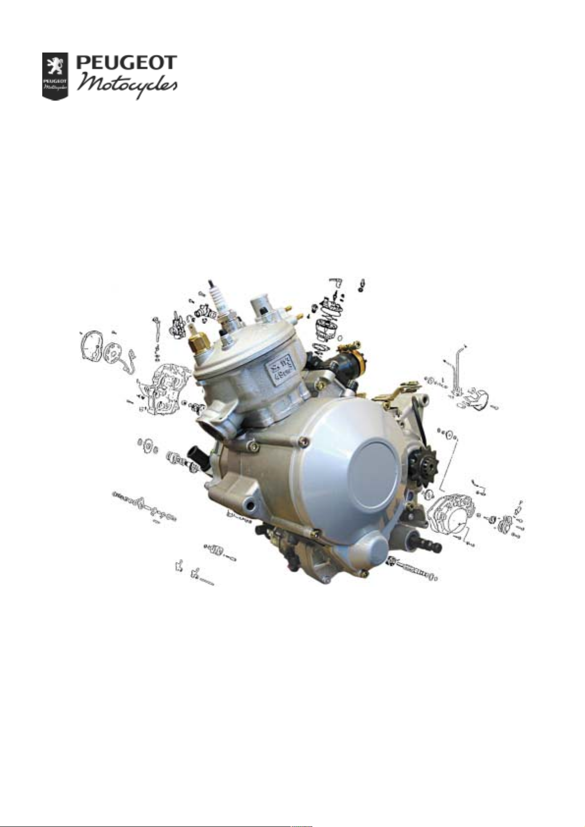
SALES DIVISION
NETWORK TECHNICAL INFORMATION
WORKSHOP
MANUAL
50 cc ENGINE
MULTI-SPEED
Page 3

CONTENTS
CONTENTS
CONTENTS..........................................................................................................................................2
CHARACTERISTICS.........................................................................................................................4
Characteristics.................................................................................................................................................4
Capacities........................................................................................................................................................4
Engine markings.............................................................................................................................................4
SPECIAL IMPORTANT POINTS.....................................................................................................5
Oil and fuel.....................................................................................................................................................5
TIGHTENING TORQUES.................................................................................................................6
Tightening torques..........................................................................................................................................6
SPECIAL TOOLS................................................................................................................................7
DISASSEMBLY ...................................................................................................................................9
Putting the engine on the stand.......................................................................................................................9
To remove the magneto flywheel...................................................................................................................9
To remove the stator.....................................................................................................................................10
To remove the starter motor (depending on model).....................................................................................10
To remove the gearbox output pinion...........................................................................................................10
To remove the clutch cover ..........................................................................................................................11
To remove the clutch....................................................................................................................................12
To remove the crank assembly and balance shaft pinions............................................................................14
To remove the inlet manifold and valve.......................................................................................................14
To remove the cylinder head/cylinder assembly..........................................................................................15
To remove the piston....................................................................................................................................15
Removal of the thermostat............................................................................................................................16
Removal of the temperature sensor ..............................................................................................................16
To open the engine casings...........................................................................................................................17
To remove the gearbox and the selector system...........................................................................................18
To remove a primary or secondary shaft pinion...........................................................................................20
To remove the balance shaft.........................................................................................................................21
To remove the crank assembly.....................................................................................................................21
Checking the crank assembly .......................................................................................................................22
REFITTING SPECIFIC COMPONENTS......................................................................................23
To fit the crank assembly bearings...............................................................................................................23
To fit the box output seal..............................................................................................................................24
To fit the selector shaft seal..........................................................................................................................24
To fit the clutch lever seal ............................................................................................................................24
To fit the balance shaft .................................................................................................................................25
To fit the crank assembly..............................................................................................................................25
To fit the gearbox..........................................................................................................................................25
To fit the left side casing ..............................................................................................................................27
To check the piston.......................................................................................................................................29
To check the piston rings..............................................................................................................................29
To fit the piston.............................................................................................................................................29
To fit the cylinder .........................................................................................................................................30
To fit the cylinder head.................................................................................................................................30
To fit the right side O-ring............................................................................................................................31
To fit the crank assembly and balance shaft pinions....................................................................................31
To fit the clutch.............................................................................................................................................33
To adjust the clutch control lever .................................................................................................................35
Page 2
Reproduction or translation, even partial, is forbidden without prior written consent of Peugeot Motocycles
Page 4

CONTENTS
To fit the starter system (depending on model) and the clutch cover...........................................................35
To fit the magneto flywheel..........................................................................................................................36
MISCELLANEOUS OPERATIONS ...............................................................................................37
To remove the water pump...........................................................................................................................37
To fit the water pump ...................................................................................................................................37
To remove the oil pump and its drive pinions..............................................................................................38
To fit the oil pump........................................................................................................................................38
Page : 3
Reproduction or translation, even partial, is forbidden without prior written consent of Peugeot Motocycles
Page 5
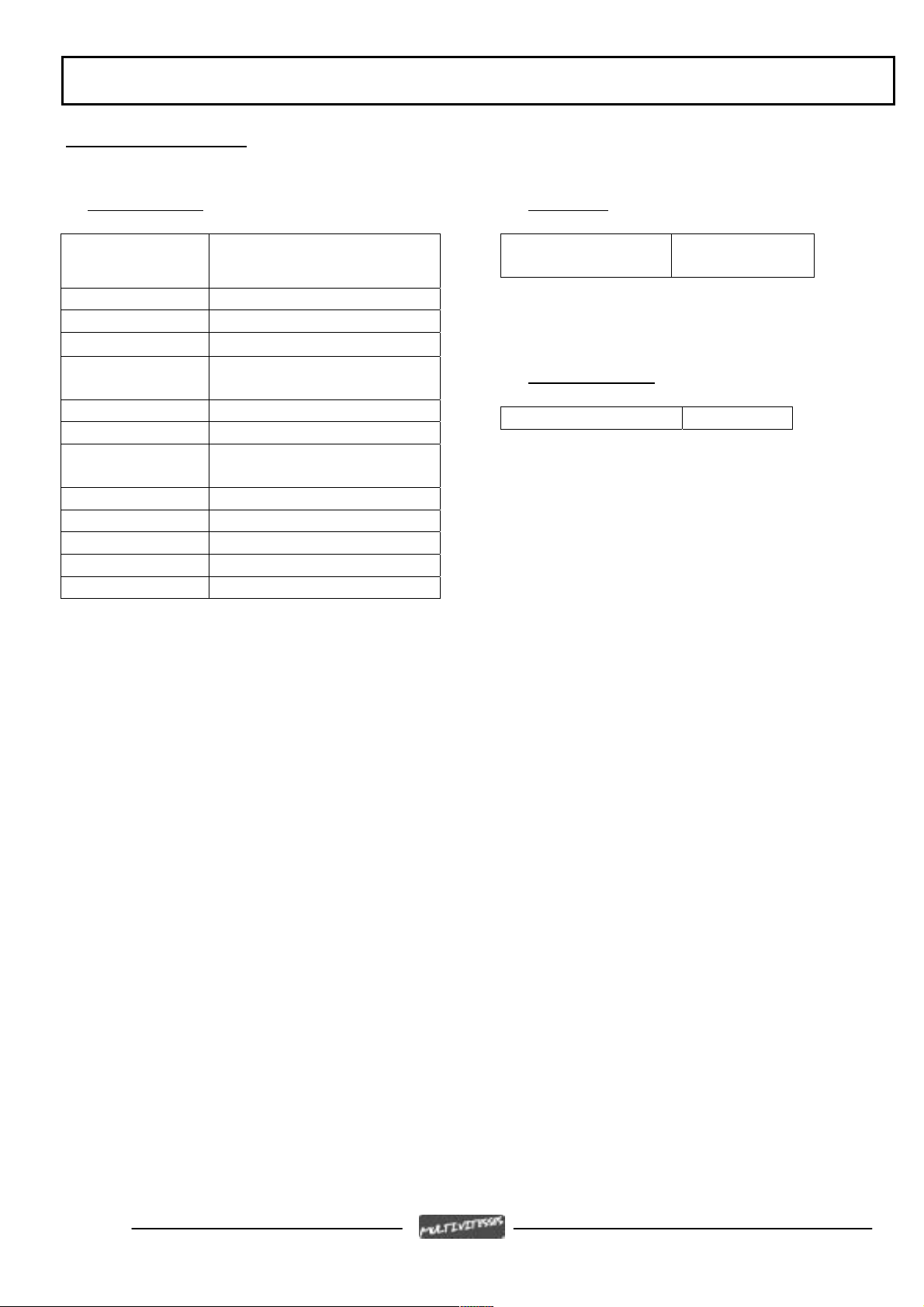
CHARACTERISTICS
Characteristics
Engine
Single cylinder 2-stroke with
balance shaft
Cooling Liquid
Bore x stroke 40.3 x 39 mm
Cubic capacity 49.7 cc
Max. power
output
1.82 kW at 5250 rpm
Max. torque at 5250 rpm
Gearbox 6-speed
Clutch Oil bath multi-disc with
manual control
Oil pump Mikuni ESOP-03
Spark plug NGK BR9ES
Magneto flywheel Ducati 85 W
Starter motor Ducati
Carburettor Dell'orto PHBN 12
CHARACTERISTICS
Capacities
Gearbox 0.75 L.
Engine markings
Engine type AM6
SAE 10W30
Page 4
Reproduction or translation, even partial, is forbidden without prior written consent of Peugeot Motocycles
Page 6

SPECIAL IMPORTANT POINTS
SPECIAL IMPORTANT POINTS
Oil and fuel
This engine is designed to run on 95 or 98 unleaded
fuel only
The separate lubrication system oil to use is Esso 2T Spécial recommended by the manufacturer.
Note:
Petrol is highly inflammable, do not smoke in the working area and avoid proximity to flames or sparks.
Work in a clear and well-ventilated area.
Page : 5
Reproduction or translation, even partial, is forbidden without prior written consent of Peugeot Motocycles
Page 7
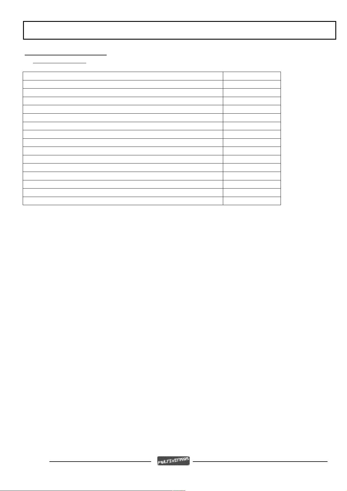
TIGHTENING TORQUES
TIGHTENING TORQUES
Tightening torques
Cylinder head 1.8 m.daN
Cylinder casings 1.1 m.daN
Transmission cover 1.1 m.daN
Water pump 1.1 m.daN
Inlet manifold 1.1 m.daN
Crank assembly pinion 7.5 m.daN
Balance shaft pinion 6 m.daN
Clutch cover 7.5 m.daN
Clutch pressure plate 0.5 m.daN
Clutch thrust bearing locknut 2.7 m.daN
Starter motor 1.1 m.daN
Rotor 5.2 m.daN
Stator 0.3 m.daN
Magneto flywheel cover 0.4 m.daN
Gearbox drain plug 1.8 m.daN
Spark plug 2.5 m.daN
Page 6
Reproduction or translation, even partial, is forbidden without prior written consent of Peugeot Motocycles
Page 8
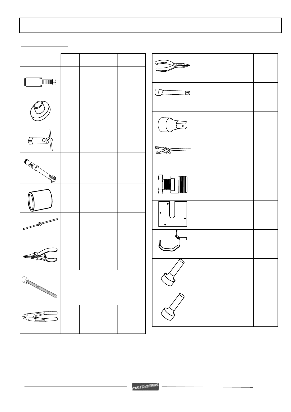
SPECIAL TOOLS
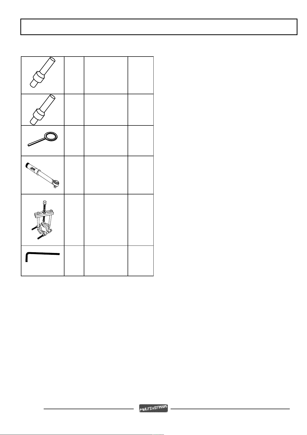
. Tool N° Description Used with
SPECIAL TOOLS
752000 Piston circlip pliers
64706 Casing extractor
and opening tool
64710 Shoulder locator 64706
64765 Engine support
68994 Torque wrench 8
Nm to 54 Nm
69098 Protective cap
large model
69104 Wing nut
69117 Exterior circlip
pliers
750069 +
Casing
opening
plate + pin
Engine
support
adapter
Extension
752235
adapter
752236
754003
64711 +
64712 +
64754
752235 1/2 extension
752236 1/2-3/8 adapter
752237 Adjustable pin
wrench
753411 Magneto flywheel
extractor
753708 Casing opening
plate
753709 Engine mount
adapter
69802 or
753977
69802 or
753978
68007
64706
750069 Stud Ø10 pitch
125
69104
753726 Crank assy lip seal
fitting tool for
primary
transmission side
753728 Selector shaft lip
seal fitting tool
750539 Tie-wrap pliers
Page : 7
Reproduction or translation, even partial, is forbidden without prior written consent of Peugeot Motocycles
Page 9
TOOLS
753729 Water pump lip seal
fitting tool
753730 Clutch lever lip seal
fitting tool
753731 Clutch locking tool
753977 Torque wrench 30
Nm to 150 Nm
Extension
752235
adapter
752237
755585 Bearing extractor
tool
755813 Valve unit safety
Allen key
Page 8
Reproduction or translation, even partial, is forbidden without prior written consent of Peugeot Motocycles
Page 10
DISASSEMBLY
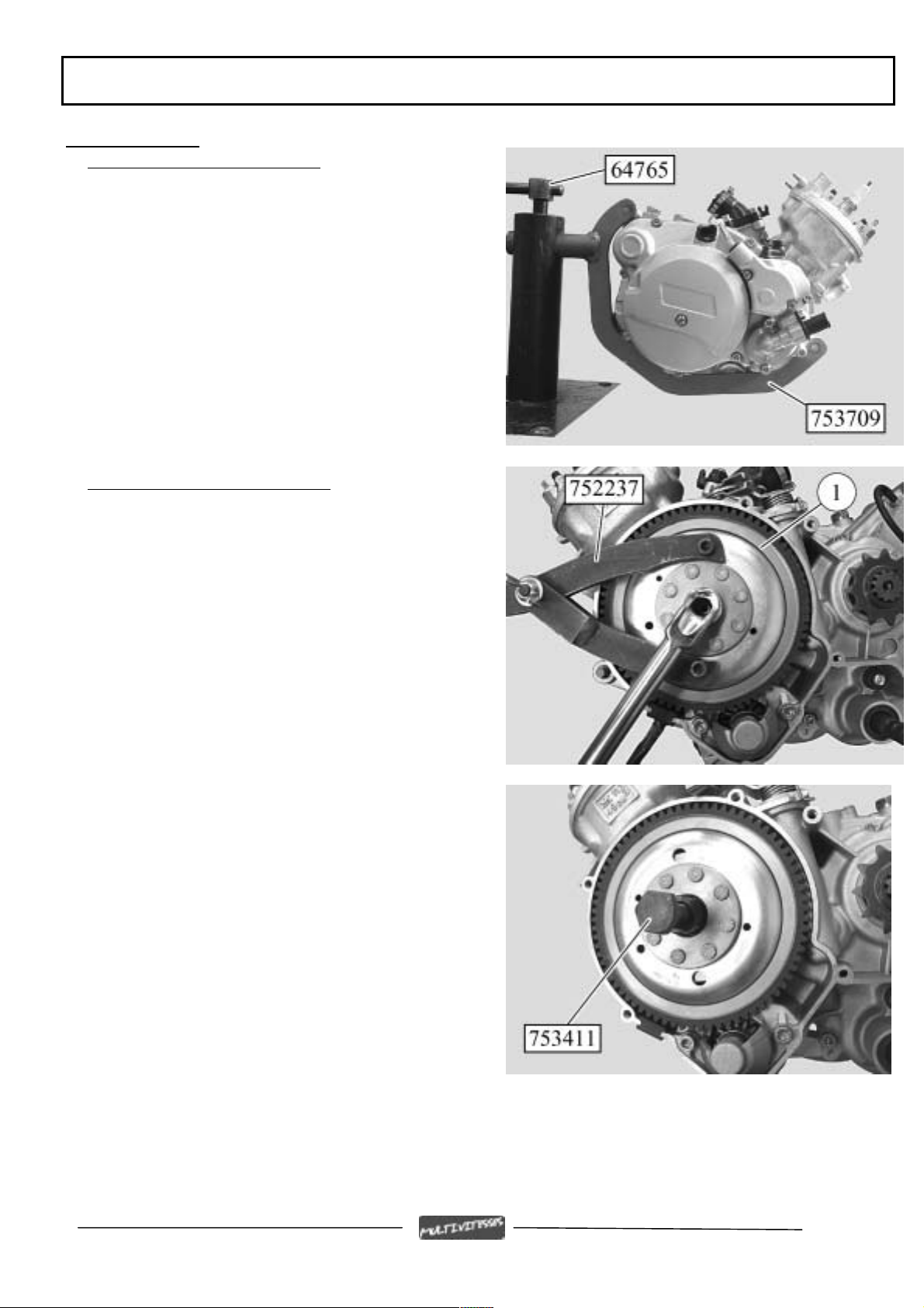
DISASSEMBLY
Putting the engine on the stand
- Fit the engine to adapter P/N 753709
- Lock the engine to the adapter using the 2 spring
pins
- Put the assembly on stand P/N 64765 clamped in
the jaws of a vice
To remove the magneto flywheel
- Remove the magneto flywheel cover
- Remove the paper gasket
- Hold the rotor (1) with the pin wrench
P/N 752237
- Remove the nut
Depending on the model, the rotor acts as the
starter ring
- Tighten flywheel extractor P/N 753411 on the
rotor
- Lock the flywheel extractor and turn the thrust
bolt until the rotor is released
Page : 9
Reproduction or translation, even partial, is forbidden without prior written consent of Peugeot Motocycles
Page 11
DISASSEMBLY
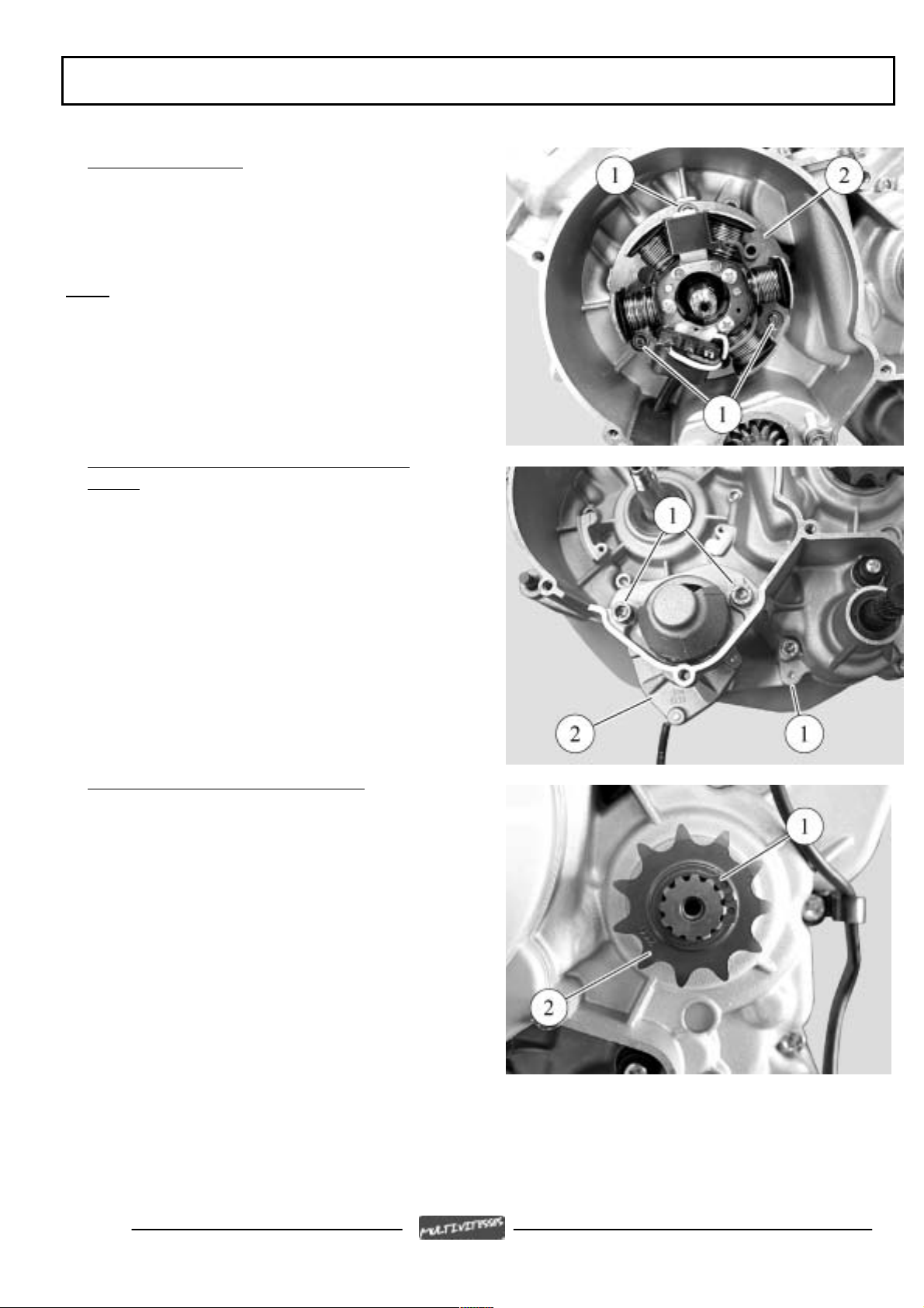
To remove the stator
- Remove the three fixing bolts (1) from the stator
plate and stator
- Remove the stator plate and stator assembly
Note:
We recommend tapping the bolts with a
hammer and drift to facilitate slackening
The 3 bolts must be renewed once removed
To remove the starter motor (depending on model)
- Remove the starter motor (2) three fixing
bolts (1)
- Remove the 2 spring pins
which lock the engine to the adapter
- Move the engine along the adapter guides to
remove the starter motor
- Re-fit the 2 spring pins
To remove the gearbox output pinion
- Remove the circlip (1) using pliers P/N
69117
- Remove the pinion (2)
- Remove the second circlip
Page 10
Reproduction or translation, even partial, is forbidden without prior written consent of Peugeot Motocycles
Page 12
DISASSEMBLY
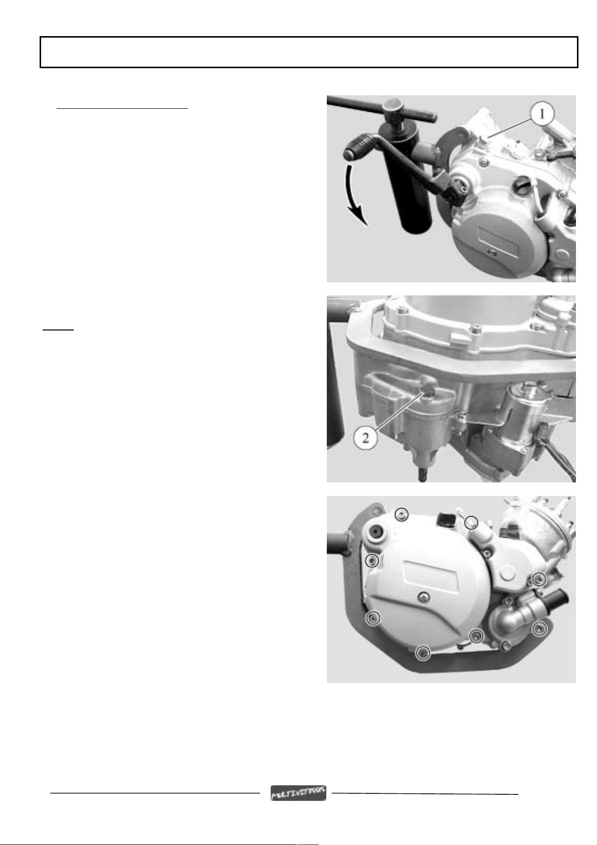
To remove the clutch cover
- Remove the kickstart pedal securing bolt
(depending on model)
- Lightly operate the kickstart pedal and hold it in
position
- Slacken off the kickstart shaft thrust bearing (1)
and release the kickstart pedal to relax the spring
- Remove the kickstart pedal
Note:
Use a recipient to recover the box oil
- Remove the bolt (2) in order to drain off the
gearbox
- Remove the cover 8 fixing bolts
- Remove the cover
- Remove the two centring pillars and the paper
gasket
Page : 11
Reproduction or translation, even partial, is forbidden without prior written consent of Peugeot Motocycles
Page 13
DISASSEMBLY
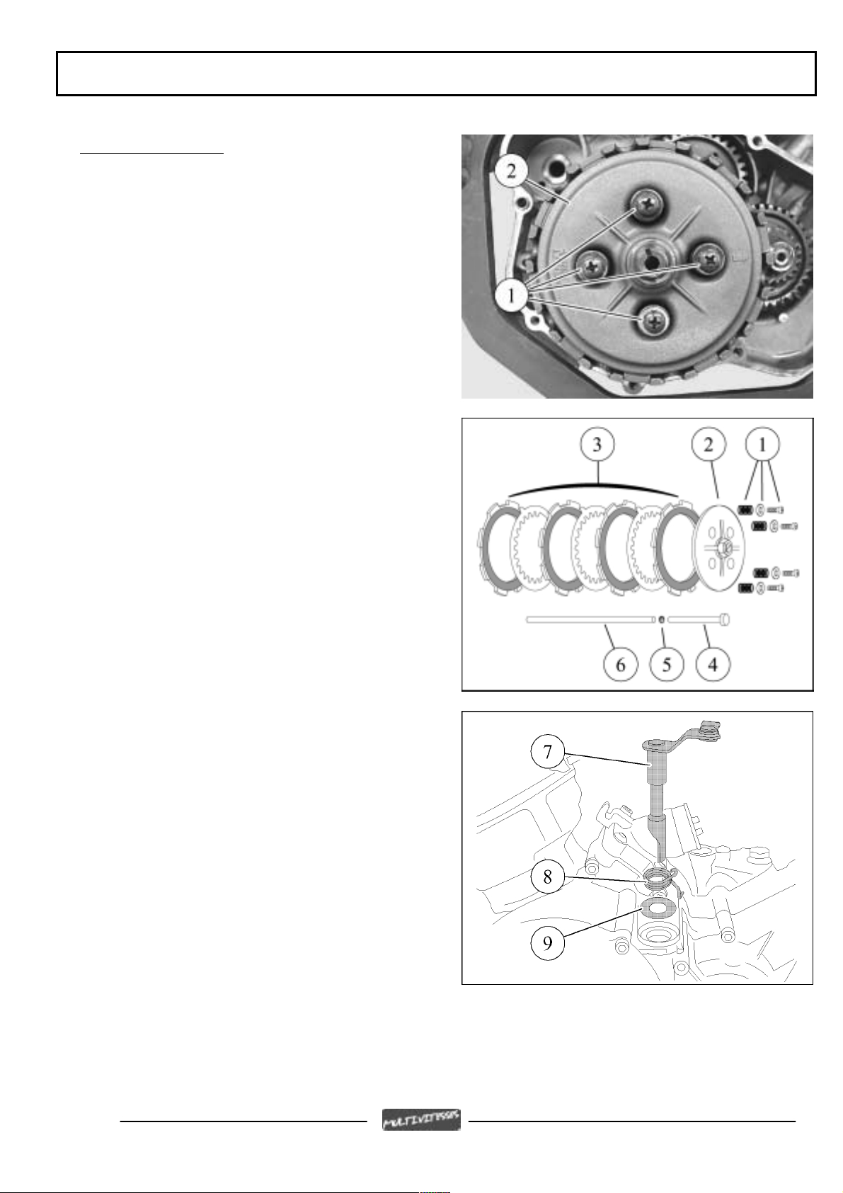
To remove the clutch
- Remove the four bolts and spring (1) from the
pressure plate (2)
- Remove the pressure plate
- Remove the assembly (3) of 4 lined discs and 3
smooth discs
- Withdraw the primary shaft:
- the piston (4)
- the ball (5)
- the thrust rod (6)
- Remove the clutch operating lever (7) with its
spring (8) and its washer (9)
Page 12
Reproduction or translation, even partial, is forbidden without prior written consent of Peugeot Motocycles
Page 14

DISASSEMBLY
- Fold down the clutch nut (10) lockwasher tab
(11)
- Lock the clutch main shaft (12) with tool P/N
753731
- Remove the nut and the washer
- Remove the clutch main shaft (12), the splined
bush (13), the cover (14), the plain washer (15) and
the tapered washer (16)
Page : 13
Reproduction or translation, even partial, is forbidden without prior written consent of Peugeot Motocycles
Page 15

DISASSEMBLY
To remove the crank assembly and balance shaft pinions
- Lock the balance shaft using a bolt (A) inserted
into one of the threaded holes
- Turn the balance shaft pinion (1) to bring the bolt
into contact with a ribbing in the case
- Remove the crank assembly nut (2)
- Remove the balance shaft nut (3)
- Remove the 2 pinions (20 and 34 teeth) and the
key (4) from the crank assembly
- Remove the 34-tooth pinion and the key (5) from
the balance shaft
To remove the inlet manifold and valve
- Remove the four inlet coupling bolts, two of
which (1) are with the safety Allen key P/N
755813
- Remove the coupling and the inlet valve
Page 14
Reproduction or translation, even partial, is forbidden without prior written consent of Peugeot Motocycles
Page 16

DISASSEMBLY
- Check that the valve assembly blades and
support are in perfect condition
Note:
The position of the limiter must be 7 mm from
the valve support
To remove the cylinder head/cylinder assembly
- Remove the spark plug
- Slacken off the cylinder head/cylinder 4
mounting nuts in the order shown, in 2 or 3 stages
- Remove the 4 nuts and washers
- Remove the cylinder head and the 2 O-rings
- Remove the cylinder and its bottom seal
To remove the piston
- Remove one of the circlips (1) with pliers P/N
752000
- Remove the gudgeon pin
- Remove the piston
- Remove the needle bearing race from the
connecting rod end
Page : 15
Reproduction or translation, even partial, is forbidden without prior written consent of Peugeot Motocycles
Page 17

DISASSEMBLY
Removal of the thermostat
- Remove the thermostat (2) two bolts (1)
- Remove the thermostat
Note:
When refitting, ensure that the degassing
hole (A) is at the highest point
Removal of the temperature sensor
Note: The engine temperature sensor (1) seal is
provided by a steel gasket
Page 16
Reproduction or translation, even partial, is forbidden without prior written consent of Peugeot Motocycles
Page 18

DISASSEMBLY
To open the engine casings
- Remove the left casing 13 securing bolts
- Fit the crank assembly protective cap P/N 68007
- Fit to casing with tool P/N 64706 fitted with
plate P/N 753708
- Fix the assembly to the casing using four bolts
(1)
- Remove the engine mount adapter 2 spring pins
- Tighten the tool centre screw until the casings
separate
Note:
When opening the casings, so that they open
evenly, use a plastic mallet to tap alternatively on
the ends of the secondary shaft and the speed
selector
Page : 17
Reproduction or translation, even partial, is forbidden without prior written consent of Peugeot Motocycles
Page 19

DISASSEMBLY
- To remove the left casing
Note:
Recover the friction washers which may
have been retained by the oil in the left casing
- Remove the 2 centring pins (2)
- Refit the engine mount adapter 2 spring pins
To remove the gearbox and the selector system
- Position the selector so that the mecanindus pin
is positioned opposite the secondary shaft fork
shaft
- Remove the selector shaft (1) fitted with its 2
friction washers
Page 18
Reproduction or translation, even partial, is forbidden without prior written consent of Peugeot Motocycles
Page 20

DISASSEMBLY
- Remove the fork shaft (2) from the secondary
shaft
- Remove the upper fork (3) from the secondary
shaft
- Turn the selector cylinder (4) to lower the
primary shaft fork (5) into the cylinder lower
groove
- Remove the selector cylinder
- Remove the secondary shaft 2
nd
fork (6)
- At the same time, remove the secondary shaft
and primary shaft assembly fitted with its fork
Page : 19
Reproduction or translation, even partial, is forbidden without prior written consent of Peugeot Motocycles
Page 21

DISASSEMBLY
- Remove the friction washer (7) from the
secondary shaft which due to the oil may have
remained stuck in the right casing
- Remove the locking ball (8) and its thrust spring
To remove a primary or secondary shaft pinion
- Remove the circlips and pinions using circlips
pliers P/N 69117
- When refitting, ensure each part is fitted in the
right position and the right way round
1. Primary shaft with 1
rd
2. 3
3. 5
and 4th gear pinion
th
gear pinion
4. 2nd gear pinion
5. 6th gear pinion
st
gear pinion
6. Circlips
7. Secondary shaft
st
8. 1
gear pinion
rd
9. 3
gear pinion
th
10. 4
gear pinion
11. 6th gear pinion
12. 2nd gear pinion
13. 5th gear pinion
14. Circlips
15. Friction washer
Note:
When changing a pinion, we recommend
changing the opposite one on the other shaft
The circlips must be renewed each time they are
removed.
Page 20
Reproduction or translation, even partial, is forbidden without prior written consent of Peugeot Motocycles
Page 22

DISASSEMBLY
To remove the balance shaft
- Remove the balance shaft (1) with the help of a
plastic mallet if necessary
To remove the crank assembly
- Remove the crank assembly (2) with its bush (3)
and its O-ring (4) by tapping it lightly on the end
with a plastic mallet if necessary
Note:
The crank assembly is a free fit in the right-
hand casing bearing
Page : 21
Reproduction or translation, even partial, is forbidden without prior written consent of Peugeot Motocycles
Page 23

DISASSEMBLY
Checking the crank assembly
- Using a set of shims, check the big end side play
- The maximum side play on the connecting rod
end must not exceed: 4/10 mm
- The out-of-round values measured on the ends of
the crank assembly should not exceed 4/100 mm et
and must be measured:
-50 mm on the transmission end
-50 mm on the magneto flywheel end
Page 22
Reproduction or translation, even partial, is forbidden without prior written consent of Peugeot Motocycles
Page 24

REFITTING SPECIFIC COMPONENTS
REFITTING SPECIFIC COMPONENTS
To fit the crank assembly bearings
Note:
- The crank assembly bearings and seals must be
renewed each time the engine casings are opened
- When the casings are opened, if the bearings stay
on the crank assembly, use tool
P/N 755585 to remove them
- If a bearing has stuck in the left casing, heat the
casing with a heat gun in order to remove it
This operation should be done quickly in order
to remove and refit a bearing to the casing
- Set one of the casings on its mating surface, heat
it (80 to 90°C) until the bearing drops out of its
own accord
- Remove the seal
- While the casing is expanded fit the new bearing
fully home in its housing
- Fit a new seal in the left casing using tool P/N
753726
Note:
The right hand side seal should be fitted
after closing the casings, fitting the O-ring and the
bush, in order to prevent the seal lips from being
damaged or from turning inside out.
Page : 23
Reproduction or translation, even partial, is forbidden without prior written consent of Peugeot Motocycles
Page 25

REFITTING SPECIFIC COMPONENTS
To fit the box output seal
- Using tool part number 753726, fit the box
output seal
To fit the selector shaft seal
- Using tool part number 753728, fit the selector
shaft seal
To fit the clutch lever seal
- Using tool part number 753730, fit the clutch
lever seal
Page 24
Reproduction or translation, even partial, is forbidden without prior written consent of Peugeot Motocycles
Page 26

REFITTING SPECIFIC COMPONENTS
To fit the balance shaft
- Fit the balance shaft (1) into the right side casing
using a plastic mallet if necessary
To fit the crank assembly
- Fit the crank assembly (2) in the right side casing
Note:
The crank assembly is a free fit in the righthand casing bearing
To fit the gearbox
- Fit the slightly greased friction washer (1) onto
the needle bearing sleeve on the secondary shaft in
the right side casing
- Fit the slightly greased thrust spring and the
locking ball (2) into their housing
- At the same time fit the secondary shaft and
primary shaft assembly with its selector fork (3)
into the right side casing
Page : 25
Reproduction or translation, even partial, is forbidden without prior written consent of Peugeot Motocycles
Page 27

REFITTING SPECIFIC COMPONENTS
- Fit the elbow fork (4) and the 5th gear idler
pinion to the secondary shaft
- Fit the selector cylinder with its 2 washers
- Position the fork guide (3) in the selector
cylinder intermediate groove
- Fit the fork (5) to the 6
th
gear idler pinion
- Position the fork guide (4) in the selector
cylinder lower groove
- Position the fork guide (5) in the selector
cylinder upper groove
Page 26
Reproduction or translation, even partial, is forbidden without prior written consent of Peugeot Motocycles
Page 28

REFITTING SPECIFIC COMPONENTS
- Fit the fork shaft (6)
- Position the selector cylinder in 4
th
gear, with the
mécanindus pin opposite the fork shaft
- Fit the selector shaft (7) fitted with its 2 friction
washers
To fit the left side casing
- Check the friction washers are fitted to:
- the secondary shaft (1)
- the selector drum (2)
- the selector shaft (3)
- Fit the 2 centring pins (4)
- Check the right side casing mating surface is
absolutely clean
- Coat the right side casing mating surface with
gasket compound
- Lightly grease the ends of the shafts
- Check the left side casing mating surface is
absolutely clean
- Fit the left side casing
- Tighten pin P/N 750069 on the end of the crank
assembly
Page : 27
Reproduction or translation, even partial, is forbidden without prior written consent of Peugeot Motocycles
Page 29

REFITTING SPECIFIC COMPONENTS
- Fit tool P/N 64706 fitted with plate P/N 753708
to the pin
- Centre the assembly on the casing using 4
bolts (5)
- Fit centring tool P/N 64710 to tool P/N 64706
- Tighten pin nut P/N 69104 until the casings are
fully closed
- Fit and tighten the 13 securing bolts
- Tightening torque: 1.1 m.daN
Note: - Check the crank assembly turns freely in
the casings
- Fit the gear selector without tightening it, turn
the primary shaft manually and check the gears
change correctly
- Lightly grease the crank assembly and bearings
with 2-stroke oil
Page 28
Reproduction or translation, even partial, is forbidden without prior written consent of Peugeot Motocycles
Page 30

REFITTING SPECIFIC COMPONENTS
To check the piston
- The piston should show no traces of scoring or
seizure
- The rings must be free in their grooves
To check the piston rings
- Carefully remove the piston rings
- Place a ring in the bore parallel to it and measure
the gap using a feeler gauge
- Piston ring gap: 0.15 mm to 0.30 mm
- Utilisation limit: 1 mm
To fit the piston
- Fit the needle bearing race (1) into the
connecting rod little end after lubricating it with 2stroke oil
- Fit the piston to the connecting rod, the
positioning spigots on the piston rings facing the
inlet side
- Fit the gudgeon pin
- Fit the circlips using pliers P/N 752000
Important:
- The circlips must be changed each
time they are removed
The circlip gaps must face upwards or downwards
(2), but under no circumstances to the side
Page : 29
Reproduction or translation, even partial, is forbidden without prior written consent of Peugeot Motocycles
Page 31

REFITTING SPECIFIC COMPONENTS
To fit the cylinder
- Fit a new base gasket (1) do not use oil or grease
- Ensure that the piston ring gaps are opposite the
piston positioning spigots
- Fit the cylinder (2) and insert it while
compressing the piston rings by hand
- Fit the cylinder over the piston by compressing
the piston rings by hand
To fit the cylinder head
- Check the O-ring housings are absolutely clean
- Fit the new O-rings to the cylinder head
- Fit the cylinder head to the cylinder
- Tighten the cylinder head securing nuts working
diagonally in 2 or 3 steps
- Tightening torque: 1.8 m.daN
- Fit the spark plug
- Tightening torque: 2.5 m.daN
Page 30
Reproduction or translation, even partial, is forbidden without prior written consent of Peugeot Motocycles
Page 32

REFITTING SPECIFIC COMPONENTS
To fit the right side O-ring
- Fit a new O-ring (1) and spacer (2) to the crank
assembly
- Using tool part number 753726, fit a new O-ring
(3), with the lip facing outwards
To fit the crank assembly and balance shaft pinions
- Fit key (1) into the crank assembly housing
- Fit the key (2) into the balance shaft housing
Page : 31
Reproduction or translation, even partial, is forbidden without prior written consent of Peugeot Motocycles
Page 33

REFITTING SPECIFIC COMPONENTS
- Fit the crank assembly pinion (3), with the
marked tooth to the outside
- Fit the balance shaft pinion (4) by lining up the
tooth gap marked with two spots (A) with the mark
of on spot (A) on the crank assembly pinion
- Fit the nut but do not tighten it
- Lock the balance shaft using a bolt (B) inserted
into one of the threaded holes
- Turn the balance shaft pinion to bring the bolt
into contact with a ribbing on the casing
- Tight the balance shaft nut (5)
- Tightening torque: 6 m.daN
- Fit the pinion (6), with the spotfacing towards
the outside, and fit nut (7)
- Tighten the crank assembly pinion
- Tightening torque: 7.5 m.daN
Page 32
Reproduction or translation, even partial, is forbidden without prior written consent of Peugeot Motocycles
Page 34

REFITTING SPECIFIC COMPONENTS
To fit the clutch
- Fit the following to the primary shaft:
- the tapered washer (1) with the round end
towards the bearing
- the plain washer (2)
- the clutch housing (3)
- the splined bush (4)
- the clutch main shaft (5)
- the tab washer (6) and the nut (7)
- Lock the clutch main shaft with tool P/N 753731
- Tighten the nut
- Tightening torque: 7.5 m.daN
- Fold over the clutch nut washer locking tab
- Fit the clutch control lever with its spring and
washer
- To the primary shaft, fit the piston (8), the ball
(9) and thrust rod (10)
- Fit the clutch discs starting with a lined disc (11)
and then alternate smooth and lined discs (12)
Page : 33
Reproduction or translation, even partial, is forbidden without prior written consent of Peugeot Motocycles
Page 35

REFITTING SPECIFIC COMPONENTS
- When re-assembling, ensure that the marks (A)
on the smooth discs are offset by 120° from the
others
- Fit the pressure plate (13) lining up the arrow (B)
on the plate with the round imprint (C) on the
clutch main shaft
- Fit the pressure plate springs (14) and the 4 bolts
and washers (15)
- Tightening torque: 0.5 m.daN
Page 34
Reproduction or translation, even partial, is forbidden without prior written consent of Peugeot Motocycles
Page 36

REFITTING SPECIFIC COMPONENTS
To adjust the clutch control lever
- Slacken the pressure plate locknut (1)
- Bring the lever into contact with the control rod
- Turn the centre bolt (2) on the pressure plate in
order to set the control lever at 30° to the magneto
flywheel cover mating surface
- Tighten the locknut without altering the
adjustment
- Tightening torque: 2.7 m.daN
To fit the starter system (depending on model) and the clutch cover
- Fit the spring (1) to the starter shaft- Fit the
spring (1) to the starter shaft
- Fit the starter dog (2), the starter release
mechanisms (A) lining up with the return spring
arm (B)
- Fit the starter motor dog (3)
- Fit the 2 locating pins and a new paper gasket
- Fit the clutch cover, turn the crank assembly by
hand, if necessary, to mesh the water pump pinion
with the crank assembly pinion
- Fit the cover 8 fixing bolts
- Tightening torque: 1.1 m.daN
- Fit and gently operate the kickstart pedal and
hold it in position
- Fit the kickstart shaft bump stop
- Tightening torque: 3 m.daN
- Release the kickstart pedal
Page : 35
Reproduction or translation, even partial, is forbidden without prior written consent of Peugeot Motocycles
Page 37

REFITTING SPECIFIC COMPONENTS
To fit the magneto flywheel
- Fit the stator assembly
- Fit and tighten the stator assembly (2) two fixing
bolts (1)
- Tightening torque: 0.3 m.daN
- Fit the rotor (3) to the crank assembly ensuring it
is positioned on the key
- Lock the rotor with the adjustable pin wrench
P/N 752237
- Fit and tighten the rotor nut
- Tightening torque: 5.2 m.daN
- Fit the gasket and the magneto flywheel cover
- Tightening torque: 0.4 m.daN
Page 36
Reproduction or translation, even partial, is forbidden without prior written consent of Peugeot Motocycles
Page 38

MISCELLANEOUS OPERATIONS
MISCELLANEOUS OPERATIONS
To remove the water pump
- Remove the clutch cover 8 fixing bolts
- Remove the clutch cover
- Remove the water pump cover (1) 2 fixing bolts
- Remove the cover
- Remove the two centring pillars and the paper
gasket (2)
From inside the clutch cover, remove:
- the circlip (3)
- the washer (4)
- the 30-tooth nylon pinion (5)
- the drive pin (6)
- the washer (7)
- the impeller with its shaft (8)
- the seal (9)
- Check the condition of the impeller shaft, if it is
shows signs of wear, change the impeller
To fit the water pump
- Using fitting tool P/N 753729, fit a new lightly
greased gasket (9)
- Re-assemble in the reverse order to
disassembly
Note:
A new circlip and paper gasket must be
used each time they are removed
Page : 37
Reproduction or translation, even partial, is forbidden without prior written consent of Peugeot Motocycles
Page 39

MISCELLANEOUS OPERATIONS
To remove the oil pump and its drive pinions
- Remove the clutch cover 8 fixing bolts
- Remove the clutch cover
- Remove the oil pump cover
- Remove the oil pump two fixing bolts
- Remove the pump (1) with its O-ring
From inside the clutch cover, remove:
- the 2 circlips (2)
- the pinion (3)
- the drive pin (4)
- the washer (5)
- the pump shaft and its washer (6)
- the pinion with its 2 washers (7)
- Check the condition of the oil pump shaft, if it
shows signs of wear, change the shaft
To fit the oil pump
- Lubricate the 2 shafts
- Re-assemble in the reverse order to disassembly
Note:
New circlips and O-ring must be used each
time they are removed
Page 38
Reproduction or translation, even partial, is forbidden without prior written consent of Peugeot Motocycles
Page 40

RECOMMENDED
REF: 757068
For reasons of continuous improvement, Peugeot Motocycles reserves the right to modify, delete or add any part number quoted
DCDC/PS/ATR printed in EU 02/2002 (photos non-contractual)
Reproduction or translation, even partial, is forbidden without prior written consent of Peugeot Motocycles
Page 41

Visit RepairManualClub.com for more
motorcycle manuals
Buy Motorcycle Gear and
Equipment
Buy Helmets, Jackets, Pants
Buy Everything Motorcycle at
Amazon.com
Visit RepairManualClub.com for more
motorcycle manuals
 Loading...