

PEUGEOT XP6 50 User Manual
PEUGEOT XP6 50
Manuel d'atelier (EN ANGLAIS)
G.H.E. MOTORHISPANI
A, S.L
.
GARAGE HANDBOOK
INTRODUCTION
This garage manual refers to the AM6 engine, equipping the following vehicles:
- Furia 6V Cross
- Furia 6V Supermotard
MOTORHISPANIA RECOMMENDS
2 stroke engine:
• MOTUL POWERLUBE SEMI-SYNTHETIC 2T
Gearbox oil:
• TRANSOIL 10W30
Grease:
• GREASE 100
ADVICE
A good repairer acts with order and methodically
Use the appropiate tools, gaining time and a professional image.
Página 2 de 34

CONTENTS
TECHNICAL FEATURES REPLACEMENT
Engine part .................................................. 2 Water pump .............................................. 24
Cycle part .................................................... 2 Oil pump .................................................. 25
Capacities and types ................................... 3
Tightening motor and cycle......................... 3
Special tools ................................................ 3 IGNITION AND ELECTRICAL CIRCUIT
Maintenance...................………………….. 4
Electronic ignition .................................... 28
DISASSEMBLY
Disassembly of engine ................................ 5 Neutral gauge........................................… 28
Disassembly of magneto ............................. 6 Cooling system temperature gauge.......... 28
Disassembly of clutch cover ....................... 7 Min. oil level gauge...............................… 28
Disassembly clutch ..................................... 7 Horn ......................................................... 28
Disassembly of crankshaft pinions Socket ....................................................... 28
and camshaft ..............................…………. 8 Indicators .................................................. 29
Disassembly of inlet pipe and Principle scheme....................................... 30
plate valve ...................................………… 8 Scheme legend.......................................... 31
Disassembly cylinder head ......................... 9 Cable plan ................................................ 32
Disassembly of cylinder ............................. 9
Disassembly of piston ................................ 9
Disassembly of exhaust pinion ................... 9 CONTROL
Openin
g of cases .................................... 10
Disassembly of stick and gearbox ............. 11 Elements of the gearbox ........................... 13
Disassembly of camshaft ........................... 11 Connecting rod/crankshaft set................... 15
Disassembly of crankshaft .......................... 11 Piston ........................................................ 17
ASSEMBLY
Replacement of bearings/joints ............…... 12 Clutch ....................................................... 22
Assembly of gearbox .................................. 13 Ignition advance ....................................... 26
Assembly of selector shaft ......................... 14 Oil level of gearbox ................................. 27
Assembly of camshaft.... .................……… 15
Assembly of connecting rod/crankshaft
in right case ................................................. 15
Closing of left case ..................................... 16 ADJUSTMENTS
As
sembly of the piston ............................... 17
Assembly of the cylinder ............................ 17 Engine clutch lever...................………… 24
Assembly of the cylinder head ................... 18 Ignition advance ....................................... 26
Assembly of plate valve and inlet
pipe ............................................................. 19
Assembly of crankshaft right joint ............. 20
Assembly pinions crankshaft and cam
shaft ............................................................ 20
Assembly of the clutch ............................... 22
Clutch lever regulation ............................... 24
Starting shaft/clutch cover .......................... 25
Assemblyof magneto .........................……. 26
Principle and regulator ............................. 28
Lights ....................................................... 28
Cylinder .................................................... 17
Segments .................................................. 17
Thermostat valve ..................................... 18
Plate valve .......................................... 19
Oil pump .................................................. 25
Página 3 de 34
Assembly of exhaust pinion ....................... 27
Filling of gearbox ....................................... 27
TECHNICAL FEATURES
ENGINE PART
Name of
Type: ........................................FU01
Engine marking: only engine type is inscribed, not
num
ENGINE: MOTORI MINARELLI type AM6
2 stroke monocylindrical type, with separate
greasing and liquid cooling by means of circulation
pump.
Diameter and distance: ......... Ø40.3x39mm
Cylinder capacity: ................. 49.7 cc
B compression relation ......... 12:1
R compression relation ......... 6.86:1
Transmission:
Exhaust pipe: ............ 177º
Transfer: ................... 125º
Admission: ..........…. plate valve
Idling pattern: .............….. 1800 rpm +/- 200
Power: .......... 1.82Kw ISO at 5250 rpm
Max. Par.: ….. 3.23 mdaN ISO at 5250 rpm
IGNITION: Type CDI
-Electronic type by means of condensator discharg
(tyristor)
-Advance .......... 1.4 mm before PMS (20º)
-Spark plug ....... Resisting 5 Kohm
Type: ..NGK BR8ES or EYQUEM R1000 L
Electrode space: .................... 0.6 mm
the manufacturer: ......Furia6V
bered.
-Gearing down relation: 3.55 (20x
CH: Multidisc in oil coating with manual
CLUT
control.
GEARBOX: 6 gears
-Lubrication by means of chain and pinions
-Control by means of selector at right foot
GEARING DOWN
1 12X36 3 32,0 %
2 16X33 2,06 46,5 %
3 19X29 1,53 62,9 %
4 22X27 1,23 78,2 %
5 24X25 1,04 92,2 %
6 25X24 0,96 100 %
SECONDARY T
chain and pinions
-Gearing down relation: (12x52):
CYCLE PART
e
RANSMISSION: by means of
71)
4,33
CARBURETTOR: DELL ‘ORTO SHA 14-12
-Main jet: .......………………. 63
GENERATOR: magneto DUCATI
-Number of poles: .....……….. 6
-Power: ...……………………. 85 W
-Voltage: .....…………………. 12 V
REGULATOR: FACOMSA (with integrated
central integrator)
-Regulation tension: …………. 13.4VAC +/-0.5
STARTING: Starting pedal
SEPARATE GREASING: DELL ‘ORTO oil pump
-Variable flow
6 cc/H approx. (control between 0 and 10º
9 cc/h approx. (control at 15º)
25 cc/h approx. (control at 45º)
38 cc/h approx. (control at 71º)
-Gearing down relation: 2.03 (20x24 and 13x22)
PRIMARY TRANSMISSION: helical gears
)
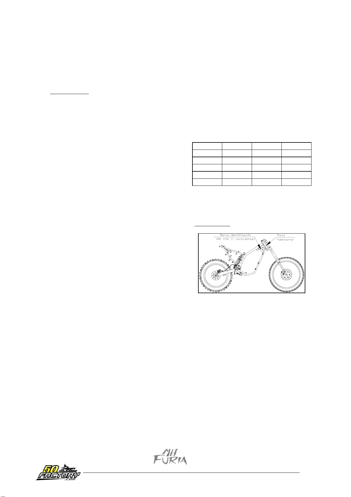
IDENTIFICATION MARK
-VIN nr. 17 characters VTVFU01A………….
CHASSIS:
Double seat in rectangular steel tube
Attack angle: 26º
Advance: 167 mm
STEERING:
-on ball beari
FRONT SUSPENSION: SHOWA
-inverted hydraulic telescopic fork
-distance: 180 mm
-bar diameter: 32 mm
REAR SUSPENSION:
-Cantilever type with oilpneumatic mono shock
absorber with helical spring
-distance: 45 mm
ngs
Página 4 de 34

FRONT BRAKE:
-AJP brake pin
-disc O220 mm with manual hydraulic control
-thickness: 4 mm
REAR BRAKE:
-AJP brake pin
-floating disc O180 mm with hydraulic control at
the stem
-thickness: 3.5 mm
TYRES: dimensions and pressures when cold
-Cross version:
Front: 2.5x21 1.5 bars
Rear: 110/80x18 1.7 bars
-Supermotard version:
Front: 100/80x17 2.3 bars
Rear: 130/70x17 2.5 bars
DIMENSIONS:
-Total length: 1995 mm
-Total width: 750 mm
-Total height: 1350 mm
WEIGHT:
-Weight when moving: 85
-Max. authorized total weight: 235 kg
CAPACITIES AND TYPES
FUEL: Super, unleaded, 98 or 95 oct.
Capacity of the tank: 6 litres
Reserve: 0.2 litres
SEPARATE GREASING: Semi synthetic oil, or
synthetic
MOTUL Powerlube semi-synthetic 2T
Capacity of the oil tank: 1.1 litres.
kg
Contents for each bar:........... 175 cc
PARES APRIETE MOTOR
Cy
linder head nut 1,8 mdaN
Crankshaft pinion nut 7,5 mdaN
Camshaft pinion nut 6 mdaN
Magneto nut 5,2 mdaN
Clutch nut 7,5 mdaN
Pressure plate screw 0,5 mdaN
Clutch counter nut 2,7 mdaN
Engine housing case screw 1,1 mdaN
Transmission cover screw 1,1 mdaN
Magneto cover screw 0,4 mdaN
Inlet pipe screw 1,1 mdaN
Starting pedal screw 3 mdaN
Gearbox casting screw 1,8 mdaN
TIGHTENING OF THE CYCLE PART
t wheel nut 4,5 mdaN
Fron
Rear wheel nut 6,5 mdaN
Fork screw 2,5 mdaN
Steering nut 6 mdaN
Fork tube inf. T screw 1,5 mdaN
Fork tube sup. T screw 2,8 mdaN
Handlebar fixing screw 2,3 mdaN
Engine fixing screw 2,8 mdaN
Swing arm nut 6,5 mdaN
Rear chassis fixing screw 2,8 mdaN
Fixing footrest bracket screw 2,8 mdaN
Upper shock absorber screw 4,5 mdaN
Lower shock absorber screw 4,5 mdaN
Front brake pin screw 2,8 mdaN
Rear brake pin screw 2,8 mdaN
Front brake disc screw 1,2 mdaN
Rear brake disc screw 0,5 mdaN
SPECIAL TOOLS
GEARBOX: Transmission oil
MOTUL Transoil 10W30
Capacity gearbox: 0.75 litres.
COOLING CIRCUIT: Protection until –20ºC
Antifreeze fluid type Procor 3000 or equivalent,
change every 2 years
Capacity of the circuit: 0.7 litres
BRAKE FLUID: fluid according to the rules DOT
3 or DOT 4
HYDRAULIC FORK: Fork oil type: SAE 20
Engine bracket
Adaptation Furia 6V
VAR tool
Opening and closing plaque
Protection cap
Special 10x125 nut
Centrer
Special nut bracket
Gauge 47 set
Wheel extractor
Clutch immobil. tool
Clutch side crankshaft driver
Wheel side crankshaft driver
Selector shaft driver
Water pump driver
Clutchstick driver
Lock pin
Adjustable immobilizer
Outer circlip pin
Página 5 de 34
MAINTENANCE
Depend
ing on the use of the vehicles, we recommend that you should apply:
The normal maintenance plan
The reinforced maintenance plan
The normal maintenance plan includes:
Service after 500 km or 3 month……….…..……Plan A
Service every 5000 km......................……………Plan B
Service every 10000 km............…………………Plan C
The reinforced maintenance plan includes:
Service after 500 km..........................Plan A
Service every 2500 km......................Plan B
Service after 5000 km........................Plan C
NOTE: The replacement of certain parts is directly related to the use of the vehicle and it is also related to
“the user’s nature”.
ACTI O NS
PL AN A
500 Kms. or 3
months
PLAN B
2.500 Kms or
5.000 Kms *
PLAN C
5.000 Kms or
10.000 Kms *
Verify:
- Adjustment of the idling
- Gas control
- Clutch control
- Front and rear brake control
- Functioning the electrical equipment
- State and pressure tyres
- Petrol tube
- Oil tube
- Brake fluid tube
- Antifreeze fluid tube
- Brake fluid level
- Antifreeze fluid tube
- Regulation of tension chain and oiling
- Tightening of screws
X X X
X X X
X X X
X X X
X X X
X X X
X X X
X X X
X X X
X X X
X X X
X X X
X X X
X X X
Replace:
- Gearbox fluid
- Spark plug
- Filtering elements of the filter box
- Brake pads ( if necessary )
- Crown, pinion, chain ( if necessary )
- Clutch disc ( if necessary )
X X
X X
X X
X
X X
X
Clean:
- Pinion head
- Combustion chamber
- Exhaust pipe exit
X
X
X
Clean:
- Carburettor
X
Vehicle testing:
- On the road
X X X
Página 6 de 34
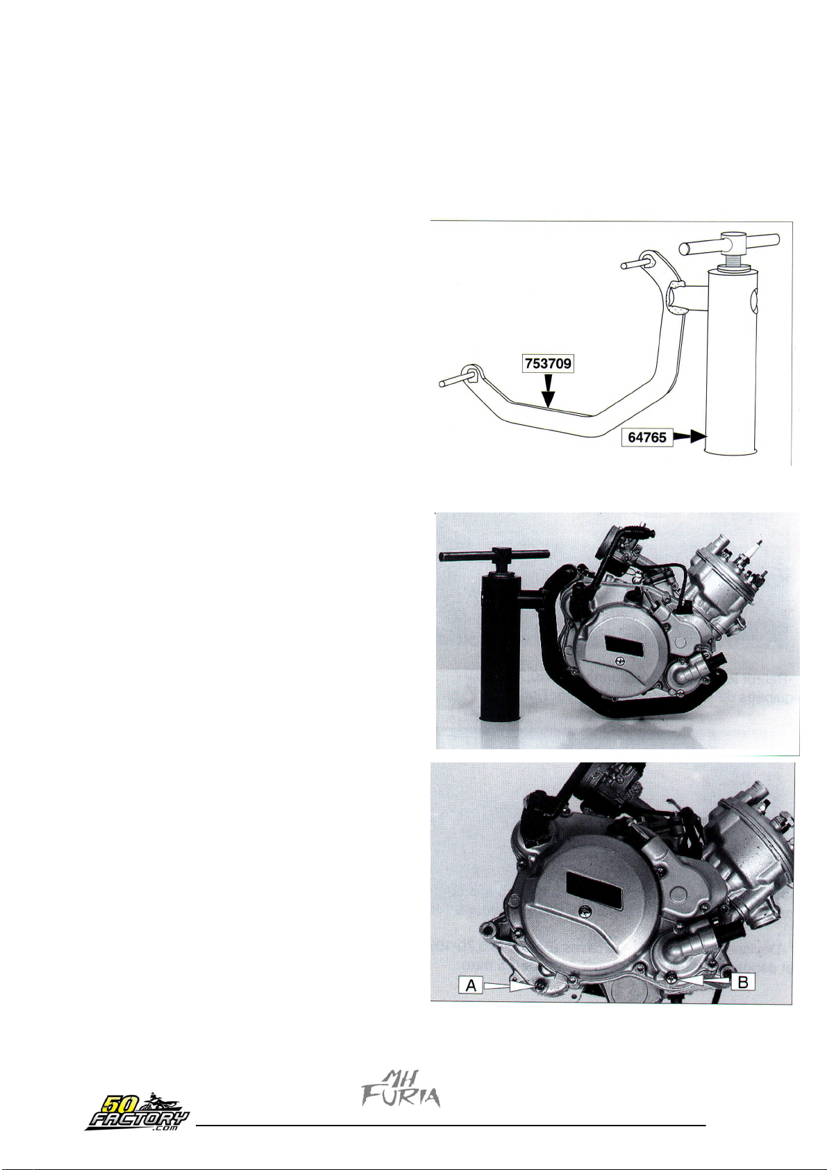
DISASSEMBLY OF THE ENGINE OF THE VEHICLE
-D
isassemble:
the petrol tube to the carburettor
the oil pipe to the pump
the two tubes of the cooling circuit (cylinder
head and pump)
gas control
the spark plug cap
the oil pump control
the filter box
-Disconn
the electrical installation of the magneto
the electrical installation of the neutral
-Disassemble the transmission chain (fast union
loosen nut of the swing fork
loosen and remove:
screw sup fastening of the engine and make it
pivot upwards
the other two screws of the engine
-Remove the engine and put it on the brack
adaptor (this bracket has to be screwed to a
bench)
ect:
et
)
-Take the oil out of the gearbox, screw (a)
-Remove the draining screw from the water
pump (B)
to empty it.
CAUTION: respect the environment, recover
the used oil
and antifreeze fluid in the appropiate containers.
Página 7 de 34
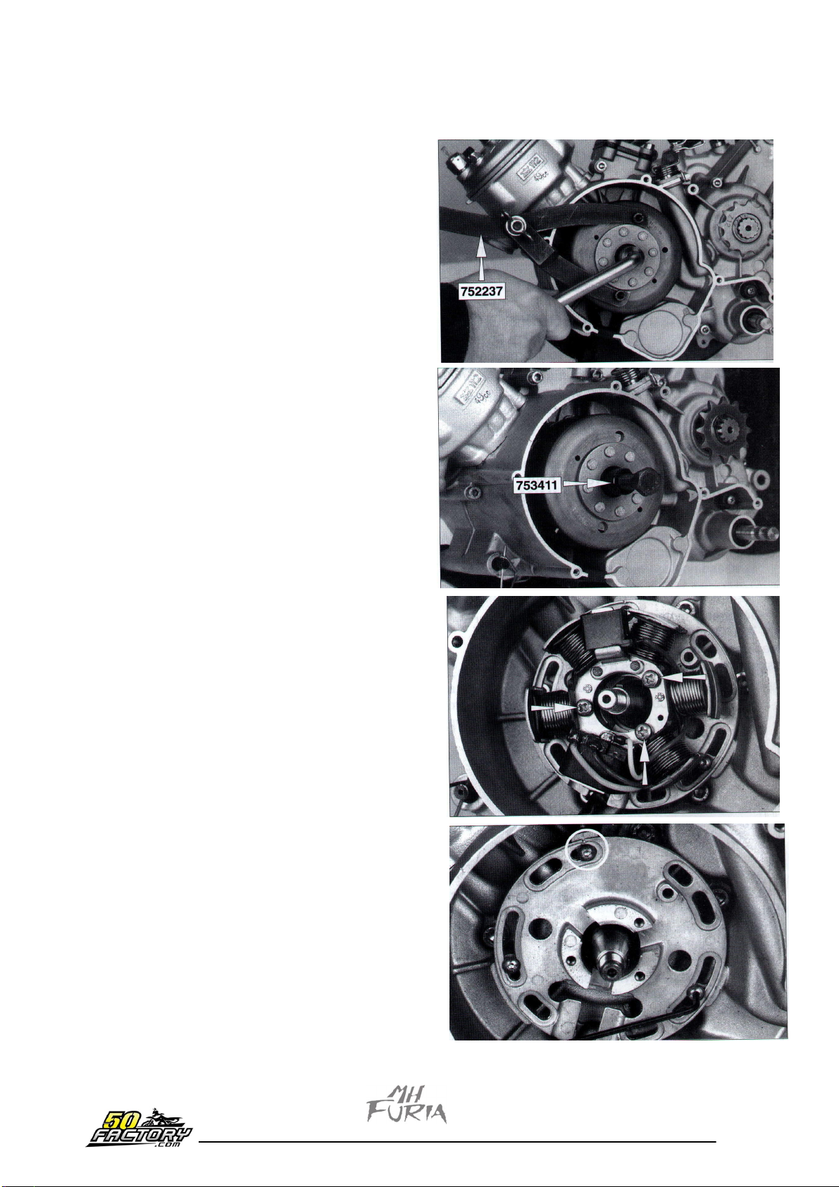
DISA
Remove the 5 screws (CHC M5x0.80-20) and
remove the cover.
Immobilize the rotor and loosen the magneto
nut with tool.
Screw the extractor off the wheel and
act on the central part of it to take out the rotor
(assembled on conical axle with pin).
SSEMBLY OF THE MAGNETO
Remove the three screws with star head
(M4x0.70-19) and their washers.
IMPORTANT: Before removing the stator base,
leave a small mark on the housing case and on
the plaque so you can find back the initial
position during the assembly.
Loosen the three screws with allen head (BHC
M4x0.70-10) and remove the stator plaque
(Allen wrench of 2.5 mm).
Página 8 de 34
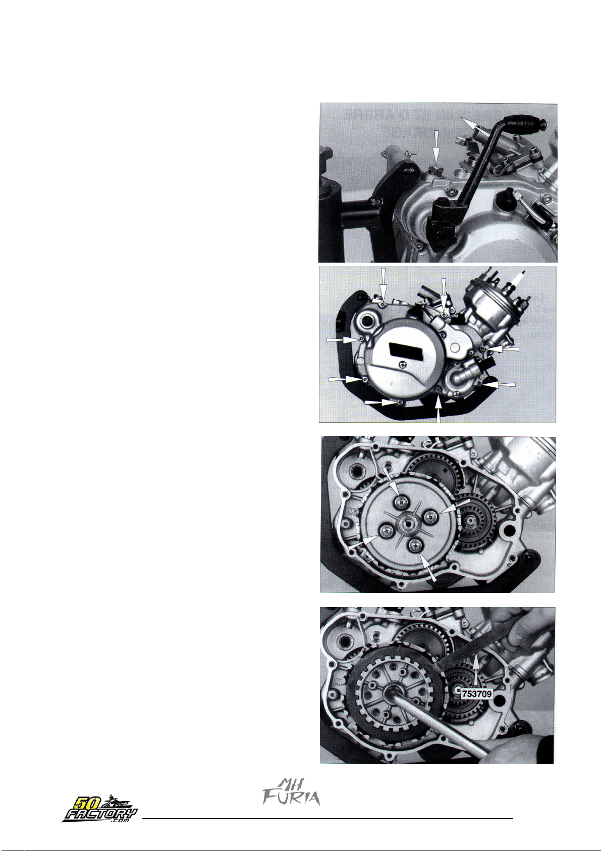
ASSEMBLY OF THE CLUTCH COVER
Activate the starting pedal slightly and keep it
in this position.
Remove the fixing screw from the pedal.
Loosen the pedal launcher screw and remove
the spring.
Loosen and remove the 8 fixing screws from the
cover (type CHC).
Remove the joint and the two centring bubbles
from the cover with the housing case.
IMPORTANT: Write down the position of the
starting pedal on the spindle to put it back
during the assembly (see page 25).
DISASSEMBLY OF THE CLUTCH
Loosen and remove the 4 screws (CB M5x0.80-
20), the washers and the springs from the
pressure plate.
Disassemble the upholstery discs and the plain
ones.
Take out the primary driving shaft, the ball and
the driving stick (see page 23 A B C).
Straighten the nut brake.
Immobilize the rotor clutch with tool.
Loosen and remove the nut (wrench 17) and the
nut brake.
Disassemble the rotor, grooved separator, the
plain washer (17.2x30x0.8) and the interior
cogged conical washer (write down its position
for the assembly).
Página 9 de 34
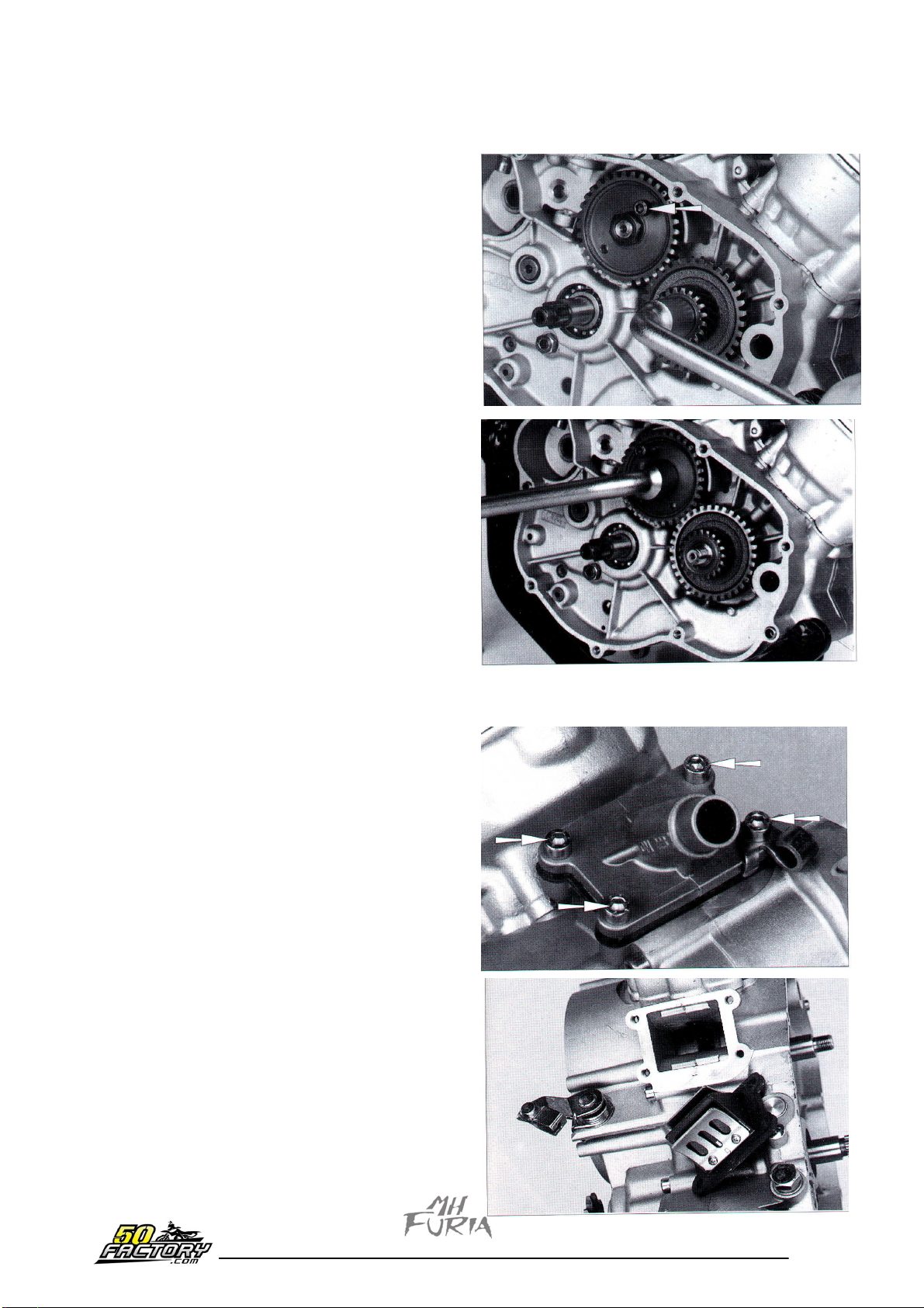
DISASSEMBLY OF THE CRANKSHAFT PINIONS
AND OF THE CAM SHAFT
Put
a screw (type CHC M6x1.00-25 for
example) into one of the thread holes of the
camshaft pinion, resting its end on the ribbing of
the housing case.
With the immobilixed pin in rotation, loosen the
crankshaft nut (wrench 17) and the cam shaft
nut (wrench 19) and remove them.
Disassembly of the crankshaft:
The two pinions (20 cogs and 34 cogs), the
in (note the direction of the pinion 20 z, mark
towards the nut).
The smooth washer (812.3x22x0.8), the pinion
(34 cogs) and the pin.
DISASSEMBLY OF THE INLET PIPE AND PLATE VALVE
Loosen and remove the 4 fixing screws (CHC
M6x1.00-20)
from the inlet pipe.
Disassemble the pipe and the plate sheet
(overhaul of
valve is in the chapter dedicated to the
assembly, page 19).
Disassemble the clutch lever with its spring and
washer.
Página 10 de 34
 Loading...