

Page 1

Motor FB-0-1-2-4
GB
WORKSHOP MANUAL 50 cm3
Page 2

CONTENTS
ENGINE PART
Designation Page
- Contents, ............................................................. 1
- Main characteristics, ............................................ 2
- Maintenance plan,................................................ 3
- Putting into service, ............................................. 4
- Special tools,........................................................ 5
- Tightening torques............................................... 5
Dismantling
Designtation Page
- Removing the engine from the vehicle, ............... 6
- Placing the engine on the support, ...................... 6
- Removing the cooling system,............................. 6
- Removing the flywheel,........................................ 6
- Removing the oil pump, ....................................... 7
- Removing the starter motor, ................................. 7
- Removing the carburettor and choke, ................. 7
- Removing the intake valve and connecting part,. 7
- Removing the complete primary drive assy, ........ 7
- Removing the kick starter system,....................... 8
- Removing the relay unit, ...................................... 8
- Removing the cylinder head, ............................... 8
- Removing the cylinder piston assy,...................... 9
- Removing the RH housing,.................................. 9
- Removing the crankshaft from the LH housing, .. 9
- Replacing the crankshaft bearings and seals,...... 9
- Checking the crankshaft ...................................... 9
CYCLE PART
Designation Page
- Contents, ..............................................................1
- Main characteristics, ............................................ 2
- Maintenance plan,................................................ 3
- Putting into service, ..............................................4
- Tightening torques, ...............................................5
- Disc brake...........................................................14
RECOMMENDATIONS
Designation Page
- Spark plug.............................................................2
- Fuel ...................................................................... 4
- Separate lubrication..............................................4
- Relay unit ............................................................. 4
Refitting
Designation Page
- Refitting the crankshaft,..................................... 10
- Closing the engine housings,............................. 10
- Refitting the piston, ............................................ 10
- Refitting the cylinder, ......................................... 11
- Refitting the cylinder head, ................................ 11
- Refitting the relay unit, ........................................ 11
- Refitting the kick starter system,........................ 12
- Checking the driven pulley clutch, ..................... 12
- Checking the drive pulley variator,..................... 12
- Refitting the primary drive,................................. 12
- Refitting the intake valve and connecting part,.. 13
- Refitting the carburettor, .................................... 13
- Refitting the starter motor, ................................. 13
- Refitting the oil pump and setting, ..................... 14
- Refitting the flywheel,......................................... 14
- Refitting the cooling system............................... 14
ELECTRIC EQUIPMENT
Designation Page
- Electronic ignition,...............................................15
- Circuits supplied with alternative current, ........... 15
. lighting,............................................................. 15
. choke, .............................................................. 16
- Resistance check of stator,................................ 16
- Circuits supplied with direct current, .................. 17
. battery charge, ................................................. 17
. fuel gauge, ........................................................18
. oil gauge, ......................................................... 18
. horn,..................................................................18
. indicators,..........................................................18
. starter motor circuits, ....................................... 19
- Functional diagrams for electric circuits,. 20 and 21
- Key to electric circuits ........................................ 22
Trekker - Squab
1
Page 3
TECHNICAL DA TAS
Main spécifications
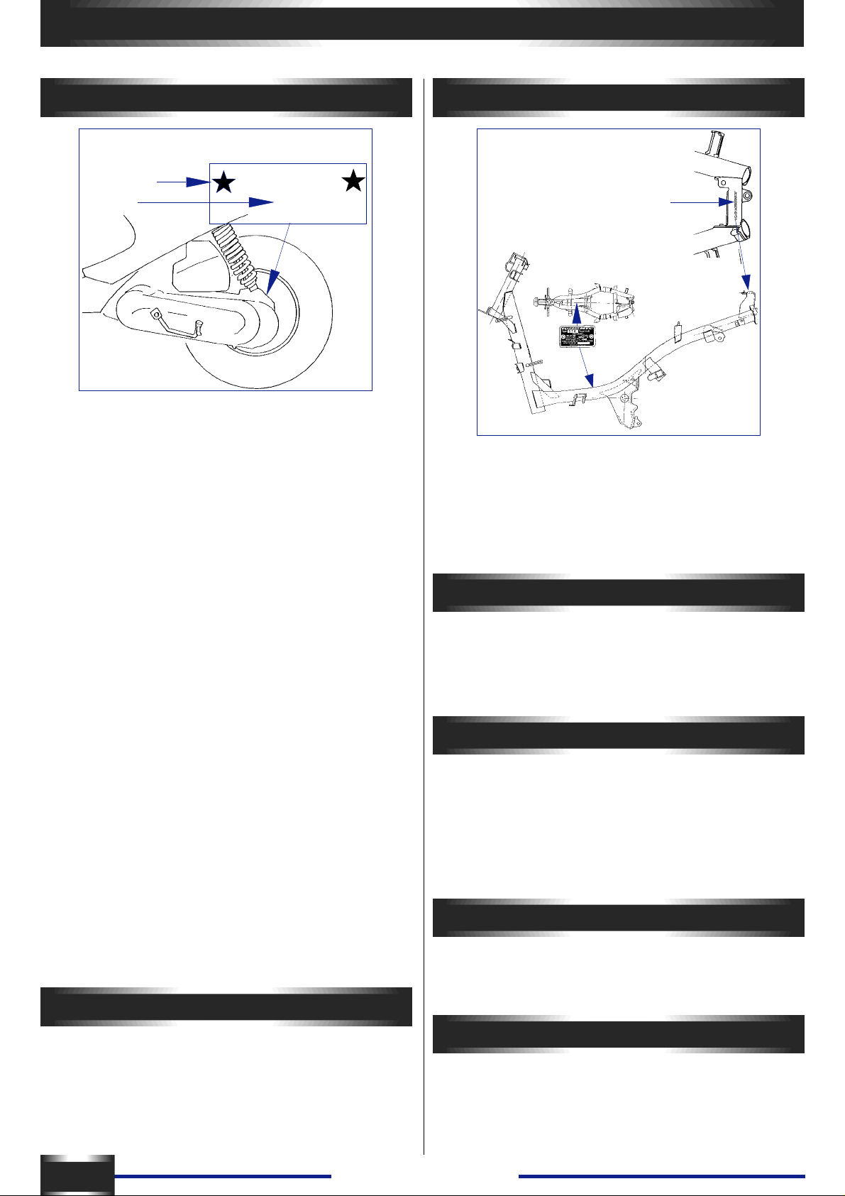
ENGINE MARKING
Number
Type
FB2 ENGINE
Forced-air cooled 2 stroke engine :
- Bore and stroke : ................................................ 40 x 39.1
- Cylinder capacity : ............................................. 49.13cm3
- Compression ratio : ...................................................6.6:1
- Maximum power (ISO) : ..........................................3.1 kw
Distribution :
- Exhaust port : ...........................................................160c°
- Scavenging port : .......................................................1 10 °
- Air intake : .....................................by reed valve induction
- Ignition :.......................CDI (capacitive-discharge ignition)
- Spark advance : ....................................... 13° before TDC
- Spark plug ...................................................Resistive 5KÙ
..................................................................... NGK - BR7HS
.................................................................. EYQUEM R 850
................................................................. BOSCH WR4AC
- spark plug gap :.....................................................0.6mm
Carburettor :..........................................GURTNER P A350
- Idling speed :....................................1800 rpm ± 1 00 rpm
- Initial position of the pilot air adjusting screw :
- Anticlockwise rotation : ..................................... 1/2 to 13/4
- Needle with 3 levels :.................................. clips at the top
- Main jet :........................................................................74
Flywheel magneto :
- Number of poles :............................................................6
- Power : .......................................................... 2500t = 55w
........................................................................ 5000t = 85w
Starter.motor : .................................................... MITSUBA
................................................................ 2000w SM10 129
................................................................. 1500w SM10254
Oil pump :.............................................................. MIKUNI
flow 24cm3 ± 1.7cm3 / hour at 3800 rpm, wide open
throttle. 1CM3 = 0.031 cubic inch
XXXXXXXX
FB2
Frame
IDENTIFICA TION MARK
Identification
plate
Identification : VGAS1A . . . . . . . . . . .
- Front tyre :...................................................... 120/90 x 10
- Rear tyre : ......................................................130/90 x 10
Pressure :
- Front :.................................................................... 1,3 bar
- Rear : .................................................................... 1,6 bar
Capacities
- Fuel tank : .............................................................. 6 litres
- Oil tank : .............................................................. 1.3 litres
- Transmission case : ............................................0.12 litre
- Under-seat storage compartment :............................. 3 kg
Dimensions
- Overall length : ....................................................1760mm
- Overail width :........................................................670mm
Excluding rear view mirror :
Overall height : ...................................................... 1110mm
Excluding rear view mirror :
Wheelbase : ..........................................................1250mm
Weight
- Complete vehicle dry weight :....................................82kg
- Vehicie weight with t anks full : ...................................88kg
T ransmission
- Clutch : .................................... centrifugai, automatic type
- Primary réduction gear : ........................ by a ribbed V-beit
- Life of belt :...................................................... 1 0 000 km
- Reducer equipped with 2 gearsets.
2
Trekker - Squab
Markings 49cc
- Left hand casing (under the starter motor)
- Cylinder head (front right)
- Cylinder (exhaust flange left hand side)
- Intake pipe (on the front «49»)
Page 4

MAINTENANCE
MAINTENANCE PLAN
Depending on how the scooter is used, it is recommended to apply either - The normal maintenance plan or
- The reinforced maintenance plan.
The normal maintenance plan includes:
- Visit at 500 km or 3 months Plan A
- Periodic maintenance every 5000 km Plan B
- Periodic maintenance every 10000 km Plan C
The reinforced maintenance plan includes:
- Visit at 500 km Plan A
- Periodic maintenance every 2500 km Plan B
- Periodic maintenance every 5000 km Plan C
The reinforced maintenance is intended for vehicles used in so-called “severe” conditions: door to door sales, intensive urban
use (courrier), short journeys engine cold, areas with dusty atmospheres, frequent use of vehicles at an ambient temperature
above 30°C.
500 km or 3 mois
PLAN B
5000 km or 2500 km* 10000 km or 5000 km*
PLAN CPLAN A
CHECK :
Idle speed adjustment XXX
Throttle XXX
Oil pump control XXX
Functioning of the electric equipment XXX
Front and rear brake control XXX
Fuel pipes XXX
Oil pipes XXX
Front brake fluid pipes XXX
State and pressure of tyres X
State, pressure and wear of tyres XX
Brake fluid level XXX
Level of battery electrolyte XXX
Tightening of nuts and bolts XXX
REPLACE :
Relay unit oil XX
Spark plug XX
Filter element of the intake silencer XX
Front brake pads (if necessary) X
Rear brake linings (if necessary) XX
Drive pulley rollers (if necessary) XX
Transmission belt X
CHECK AND UNCLOG
Piston X
Cylinder head X
Exhaust port X
CHECK AND LUBRICATE
Driven pulley :
movable driven face and needle bearing X
Drive pulley :
movable drive face and rollers X
Kick : driven gear and link ring X
CLEAN AND ADJUST
Carburettor X
VEHICLE TEST
Road test XXX
* reforced maintenance
Trekker - Squab
3
Page 5

INSTRUCTIONS FOR MAKING OPERATIONAL
1. Preparation of the battery
(dry charged)
- Remove the battery .
- Remove the six cell caps and the breather tube cap.
- Fill the battery with électrolyte up to the level marked
UPPER LEVEL (35% sulphuric acid 1.28 g/CM3),
Ref :........................................................... 1 litre : 752740
................................................................ 5 litres : 752741
- Leave the battery to settle for half an hour. Top up the
level if necessary .
- Charge the battery for 1 to 2 hours with a current of
400m.A (0.4A).
- Replace the battery and connect the breather tube.
- Connect up the red positive leads to the battery positive
terminal, then the green negative lead to the battery earth
terminal.
- From then on, the battery can be topped up if necessary ,
using distilled water only .
2. Fuel
Capacity : ..............................................................6 litres
- Conventional 4-star petrol.
- Lead free petrol 98 octanes.
3. Separate lubrication:
4. Putting fuel and oil circuits into
opération:
- Put one litre of fuel mixture with 4% oil into the fuel tank.
- Fill up the oil tank.
- Start the engine: make sure that the oil circuit is
completely primed. Remove the oil bleed screw from the
pump to allow air in the circuit to escape. When a
continuons stream of oil issues from this hole, replace the
bleed screw with its fiber washer.
For this : disconnect the oil intake hose to the carburettor
and check that it drips, frequency depending on the
engine’s speed.
- Top up the fuel tank with pure 4 star petrol.
5. Checking the oil level in the
transmission case:
- Unscrew and remove the oil filler hole screw A and
make sure that the oil level is flush with the level of the
filling hole. The vehicle must be positioned on its stand
and on a level surface.
Esso Oil SAE 80 W 90
REF : .................................................................... 753009
capacity 0. 1 2 litre
A = 1.2m.daN.
Capacity : ..........................................................1.3 litres.
- Fill up the oil tank with semi-synthetic engine oil for 2stroke engines with separate lubrication,
- T ype TC (API standard), type TSC3 (ASTM standard), -
- T ype FC (JASO st andard) or a synthetic oil.
PEUGEOT MOTOCYCLES recommends :
.......................................ESSO : 2T Special performance
.........................................................ESSO : 2T Synthetic
6. Checks before delivery to the
customer:
- In particular , check the tightening of the Wheel nut s ... -
front : .................................................................... 6m daN
- rear :.............................................................. 1Om daN
- Check the tightness of the nuts and bolts.
- Check brake adjustment and eff iciency.
- Cold tyre pressure:
FRONT
- pressure : ......................................................... 1.3 bar
- size :..........................................................120/90 x 10
REAR
- pressure : ......................................................... 1.6 bar
- size :..........................................................130/90 x 10
- Make sure all lights and signals operate correctly
(taillight, turnsignals, stop light, horn), and various
warning lights.
- vehicle road test.
4
Trekker - Squab
Page 6

Engine
TIGHTENING TORQUES AND SPECIAL TOOLS
TIGHTENING TORQUES SPECIAL TOOLS
Assembly screws for :
- Housings : ........................................................ 1m.daN
- Covers :............................................................ 1m.daN
- Intake connecting part : .................................... 1m.daN
- Starter motor : .................................................. 1m.daN
- Stator :.............................................................. 1m.daN
- Sensor :............................................................ 1m.daN
- Fan : ................................................................. 1m.daN
- Carburettor : .................................................. 0.8m.daN
- Oil pump :...................................................... 0.8m.daN
- Cylinder head : .............................................. 1.2m.daN
- Drive pulley :..................................................... 4m.daN
- Driven pulley :................................................ 4.5m.daN
- Rotor : .............................................................. 4m.daN
- Oil plug : ........................................................ 1.2m.daN
- Spark plug : ...................................................... 2m.daN
Frame
- Front wheel axis nut : ........................................ 6m.daN
- Rear wheel nut : ............................................. 10m.da N
- Engine joint on rod :........................................... 6m.daN
- Rod joint on chassis : ..................................... 2.2m.daN
- Rear shock absorber upper fixation :.............. 1.6m.daN
- Rear shock absorber lower fixation : .............. 1.6m.daN
- Exhaust nuts on cylinder : .............................. 1.6m.daN
- Handlebar nut :.................................................. 4m.daN
- Steering lock nut :.............................................. 7m.daN
- Service cradle mount............................................... 64765
- Adjustable adapter for engine service cradle......... 752026
- Flywheel holder ....................................................... 68570
- Snap ring pliers ..................................................... 752000
- Protective end, small model for flywheel magneto remover
.................................................................................. 68007
- Puiler tool ................................................................ 64706
- Crankshaft end protector......................................... 69098
- Shouldered centring tool.......................................... 64710
- Screw on torque handle........................................... 69104
- Compresser tool, ail types of clutch....................... 752127
- Tubular socket wrench 39 ..................................... 752361
- Adjustable pin type face wrench ............................ 752237
- Set of half sheils 0 52 .............................................. 64709
- Puiler tool .............................................................. 750807
- Support washer .....................................................750808
- Surface plate 250 x 160 x 50................................. 750541
- Comparator (adapts to pattern plate accessory..... 750969
- Torque wrench + extension + reducer .....................69802
- Flywheel puller supplied with 68007 protector ....... 750806
- Blooking tool.......................................................... 752370
- Pliers for circlips ...................................................... 69117
- Spindle .................................................................. 750069
- Steering tools ........................................................ 752948
Standard
- Screw and nut ø 5mm : ...................... 0.45 to 0.6m.daN
- Screw and nut ø 6mm : ........................ 0.8 to 1.2m.daN
- Screw and nut ø 8mm : ........................ 1.8 to 2.5m.daN
- Screw and nut ø 1Omm : ...........................3 to 4m.daN
- Screw and nut ø 12mm : ............................ 5 to 6m.daN
Trekker - Squab
5
Page 7
REMOVAL
Removal of the engine
- Remove :
- All side casings
- Disconnect :
- Fuel line from the carburettor,
- Fuel tap vacuum hose,
- Oil pump control cable
- Throttle control cable,
- Oil iniet piping at the pump (large
hose)
- Radio interference suppressor cap
- Rear brake control cable
Disconnect :
- The wiring harness on the frame’s
right tube: located at the outlet of the
Flywheel magneto (under the foot
board), choke, starter motor .
Remove :
- The lower anchor bolt of the shock
absorber and the front anchor pin of
the engine.
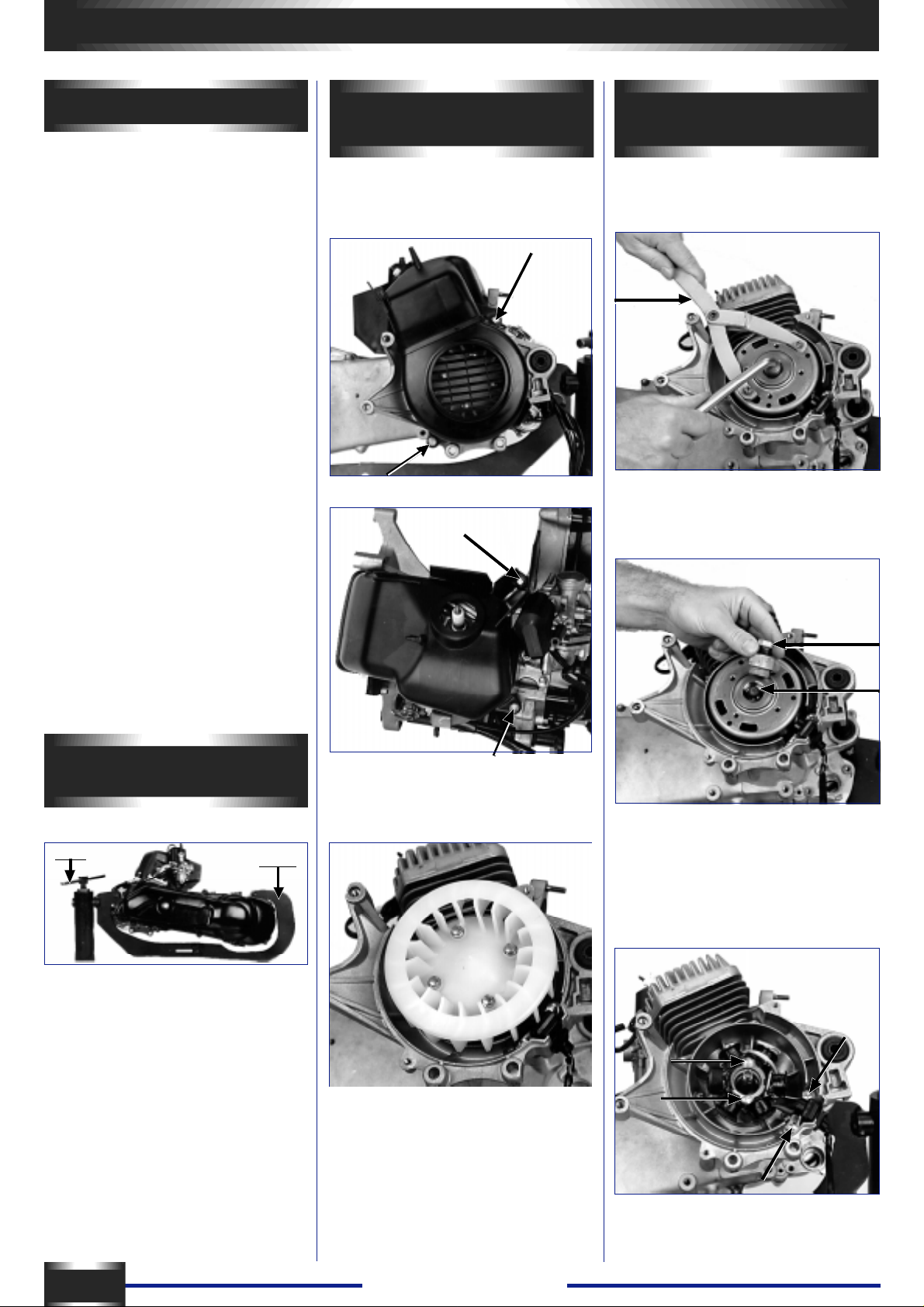
Removal of cooling
systern
- Remove the two parts of the fan
covers (4 screws).
Removal of the flywheel
magneto
- Block the rotor using a notch type pin
752237.
- Remove the nut (right-hand thread).
- Fit the crankshaft end protector
68007 onto the end of the crankshaft.
Fitting of engine on service
cradle
64765
- Place the engine onto the adapter
752026
- Place the assembly on the cradle
mount 64765 clamped in a vice
752026
- Remove the 4 fastening screws of
the fan and remove the fan.
750806
68007
- Screw the flywheel puller tool 750806
onto the rotor and tighten the centre
bolt until the rotor comes away .
- Remove the 2 fastening screws of
the sensor, as well as the 2 fastening
screws of the stator plate.
6
- Remove the coil assembly and the
sensor.
Trekker - Squab
Page 8
REMOVAL
Removal of the oil pump
- Unclip the oil inlet pipe to the
carburettor.
- Unscrew the 2 hex head socket
screws.
- Remove the oil pump and the control
flange.
- Remove the 2 square fastening nuts
Q from their housings.
- Remove the flexible washer lodged
between the pump and the shaft
bearing of the oil pump.
Removal of the
carburettor / choke
assembly
- Take off the 2 fastening screws from
the carburettor and remover the
carburettor / choke
assembly , as well as the isothermal
spacer .
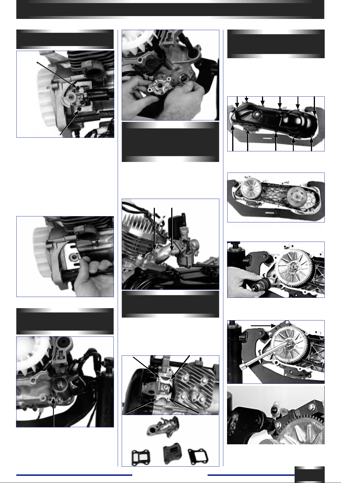
Removal of the primary
drive system
You do not have to remove of the kick
starter arm when removing the
crankcase cover.
- Loosen and remove the 1 1 fastening
screws of the cover.
- Remove the cover with both locating
dowls.
- Adjustment: see page N° 14
Rernoval of the starter
motor
Removal of the reed
valve and intake pipe
- Unscrew and remove the 4 fastening
screws.
- Remove the intake pipe, the gasket,
the reed valve assembly and the
second gasket.
- Remove the starter drive assembly
from the starter motor.
- Hold the starter ring gear with the
tool 752370.
752370
- Free the wire harness from the
support bracket.
- Remove the 2 fastening screws and
washers from the starter motor and
pull out together with «0» ring seal.
Trekker - Squab
7
Page 9

REMOVAL
Make careful note of where this tool
comes level with the starter ring gear
plate of the starter motor in order to
make sure, when refitting, that the
pressure plate fits correcte into the
grooves of the crankshaft.
- Loosen the fastening nut (right-hand
thread) of the gear plate of the drive
pulley .
- Remove the nut, washer and plate.
- Remove the belt.
- Remove the drive pulley assembly
(variable speed drive) and the washer
on the engine housing side (12,35 X
19,75 X 1).
Rdl 12,35x19,75x1
Removal of the kick
starter system
- Actuate the kick starter spindle with
your thumb and remove the drive
ratchet and its washer .
- Remove the kickstarter lever . Using
snipe-nosed pliers (ref. 691 17), t ake
off the circlips, the washer, then
remove the kick starter toothed
section, the pull-back spring and the
bushing.
- Removal of the drive shaft (or input
shaft) from the transmission cover is
done using a mallet.
- Remove the thrust washer from the
counter shaft (14.3x26xO.5).
- Drain the transmission case
completely before removing the final
shaft (or output shaft) in order to avoid
contamining brake linings.
- Pull out the final shaft (output shaft).
- Block the clutch drum with the flywheel pinch bolt no.68570 or the adjustable pin type face wrench 752237.
752237
- Loosen the screw, remove the drum
and the clutch driven pulley assembly .
- Pull out the countershaft as well as
its friction washers (1 4.3 x 26 x 0.5)
and flexible washer (1 4 x 22 x 1.5).
Dismantling the
transmission case
After draining the transmission case:
- Remove the 5 screws securing the
cover.
Removing the cylinder
head
- Unscrew in a crosswise order the 4
screws securing the cylinder head and
cylinder block assembly .
- Remove the cylinder head and
gasket.
- Remove the cover with the drive
shaft (or input shaft), the gasket and
both locating dowls.
8
Trekker - Squab
Page 10

REMOVAL
Removing the cylinder
and piston
- Remove the cylinder and cylinder-tocrankcase gasket.
- Pack the crankcase mouth with
clean cloth or paper .
- Lean the engine to the left and take
out the wrist pin’s RH snap ring.
- Push the wrist pin from the left to the
right; this opération does not require
use of a strap.
- Take out the needie bearing race.
- Turn the inner thrust bolt of tool
750807 until the crankcase halves
split Hold the connecting rod so that it
does not knock against the crankcase
halves.
- Remove the RH half casing.
- Remove the gasket and both
locating dowls. Remove the drive
shaft of the oil pump and its locating
bush.
- Secure the plate to the crankcage by
tightening the 4 screws.
- Withdraw the crankshaft by turning
the inner thrust bolt of tool 64706.
Changing the bearings
and seals
- Heat the crankcase halves evenly to
90° so that they expand. The bearings
will drop out, drive out the seals.
- Fit the new bearings while the
crankcase halves are still warm.
- Fit the oil seals in place.
- The oil seal on the drive pulley side
should fit flush with the crankcase, the
lips being on the fl.ywheel housing
side. The seal on the flywheel side
should be approximately 9mm in.
Opening the crankcase
- Remove the 6 screws securing the
RH crankcase half.
- Fit the crankshaft end protector
68007 onto the end of the crankshaft.
- Position the puller tool 750807 onto
the crankcase half.
750807
Removing the crankshaft
assembly
- Fit the crankshaft end protector
69098 onto the end of the crankshaft.
64706
752168
69098
-Fit puller tool 647706 with the plate
752168 onto the crankcase.
Note:
If the crankshaft bearings remain on
the crankshaft; use the puller tool
64706 with the half shells 64709 (diam
= 52) to remove them. Do not forget
to fit the crankshaft end protector
69098 onto the ends of the crankshaft.
Checking the crankshaft
assembly
- The maximum side play of the
conrod big end should not exceed:
0.5mm.
- Check crankshaft alignement as
shown in the drawing (surface plate
750541, comparator 750969
The values measured at the ends
should not exceed 0.12mm.
Trekker - Squab
9
Page 11

REFITTING
Refitting the engine
Assembly of the crankshaft into the
left hand crankcase:
- Fit the crankshaft into the bearing.
- Screw the ex tended nut 750069
onto the end of the crankshaft.
64706
752168
750069
- Fit tool 64706 with the plate 752168
onto the extended nut and centre the
assembly onto the crankcase using 4
screws.
- Position the centring tool 64710.
69104
64710
Closing the crankcase halves
- Position both locating dowls in the
LH crankcase:
- Put the crankcase gasket in place
(no oil, no grease).
- Position the RH crankcase and fit it
on being careful not to damage the oil
seal where it meets the cotter key.
-Screw the extended nut 750069 onto
the end of the crankshaft.
- Position the washer 750808 (50 x 29
x 3mm).
-Position the tool 64706.
750808
Refitting the piston
- Check the cylinder and piston parts
are a matched pair.
- Fit the needie bearing race into the
conrod small end after having oiled it
(2-stroke engine oil).
- Screw the torque handie 69104 onto
the extended nut 750069 while
keeping the crankshaft assembly
steady . Continue turning the torque
handle until the crankshaft comes into
contact with the bearing.
Waming :
cabre in the crankcase.
do not jam the conrod
- Position the centring tool 64710.
- Turn the torque handle 69104 until
the crankcases close completely .
- Hold the crankshaft assembly steady
on the left hand side with the starter
ring gear.
- Grease the oil pump shaft and
position the shaft / seat assembly in
the crankcase.
- Make sure that the crankshaft
assembly can rotate normally and
drives the oil pump shaft correctly.
- Position the 6 fastening screws (3 =
L 45mm, 3 = L 70mm) and tighten
them to 1 m.dan.
Make sure the crankcase gasket is
level.
- Position the piston with the arrow
pointing towards the exhaust port.
-Push in the wrist pin.
-Fit the snap rings. It is essentiel that
they are new.
The opening of the snap ring will be
positioned at the top or at the bottom,
but under no
circumstances to the side.
In order to hold the crankshaft
assembly easily , use the rotor
positioned in its right hand side
woodruff key .
Make sure the crankshaft assembly is
correctly positioned in relation to the
crankcase mouth (the middle of the
conrod must correspond with the level
of the crankcase mouth).
10
Lubricate the crankshaft assembly
and bearings with 2-stroke engine oil.
Trekker - Squab
Page 12

REFITTING
Refitting the cylinder
- The parting face should be cleaned.
- Lubricate the piston and the cylinder
bore.
- Fit a new and dry cylinder base
gasket onto the cylinder.
- Make sure that the piston ring end
gaps are aligned with the positioning
slots.
- Position the cylinder and push it
down while squeezing the piston rings
bet-ween your thumb and middle
finger.
- Make sure the cylinder base gasket
is correctly positioned on the
crankcase using 2 threaded bolts.
Refitting the transmission
case
- Replace the oil seals and bearings if
necessary by the appropriate “ heating
and drift >, method.
- Check that the outlet channels are
clear :
Removal of the case.
Important
Smear the countershaft ends with
graphite grease in order to ensure
improved lubrication when putting the
vehicie into service.
- Position the countershaft.
- Position the final shaft (or output
shaft) while being careful not to
damage the oil seal.
If this seal is damaged, oit wîil flow to
the outside through the outiet siot
located in the retum
spring housing of the brake key; Photo
opposite.
Refitting the cylinder head
- Check thàt the gasket seat surface
of the cylinder head is not damaged.
-Position the 4 fastening screws onto
the cylinder head with washers.
- Position the cylinder head gasket
onto the cylinder head, the raised face
upwards.
- Push the cylinder head / screw /
gasket assembly onto the cylinder.
- Tighten the 4 screws progressively
and in a crosswise order (L = 95mm)
1.2 m.dan.
- Fit a thrust washer 14.3 x 26 x 0.5
onto the countershaft;
Outlet between the oil seal and the
rear wheel bearing.
- Fit on the countershaft:
· the flexible washer 14 x 22 x 1.5
· the thrust washer 14.3 x 26 x 0.5.
- Position 2 locating dowls and the
gasket.
- Position the primary shaft (or input
shaft) into its bearing using a mallet if
necessary .
- Position the cover and secure it
using 5 screws (L = 40) 1 m.dan.
-Fit the spark plug 2m.daN.
côté couvercle
ARBRE INTERMÉDIAIRE
rondelle souple
Trekker - Squab
rondelle métal
Make sure that the shafts can rotate.
Note
- Fill the case with 0.12 litre of SAE
80W 90 oil.
- Peugeot Motocycles recommends
ESSO GEAR OIL GX........ ref. 753009
- Oil filler screw 1.2m.daN.
11
Page 13

REFITTING / FITTING
Instailing the kick starter (LH
cover)
- Fit the spindle bushing and the nylon
spacer (mark 1).
1
- Position the return spring, fit the
longest hook onto the pin on the cover.
- Instail the spindle into the bushing
after lubrication.
- Fit the second hook of the spring
onto the toothed section.
- Wind the spring slightly so as to
position the kick starter spindle onto
the central rib of the cover.
- Install the washer and circlips onto
the axis of the toothed section.
- Position the drive ratchet:
place the washer over the boss of the
ratchet shaft housing
load the kick starter by about 1/8 of a
turn in order to position the ratchet
(after lubricating the
shaft),
position the ratchet stop in its housing.
(Mark 2).
2
PRIMARY
TRANSMISSION
A. Clutch and driven puiley
assembly :
1. Dismantling:
752361
- Hold the assembly using tool 752127
in a vice and loosen the special nut
with the wrench 752361 (39) or a 34
mm wrench depending on the clutch.
- Remove in the followin’g order :
. the clutch shoe assembly
. the spring
. the spring guiding sleeve
. take out the three guide pins of the
variable speed drive,
. separate the movable driven face
from the fixed driven face.
2. Refitting
- Check the oil seals of the movable
driven face.
- Assemble the fixed and movable
driven faces.
- Refit the 3 guide pins and lubricate
the ramp of the variable speed drive.
- Position the sleeve having checked
that both «0» rings are in good
condition.
- Position the spring and the clutch
assembly .
- Using the tool 752127, compress the
spring and check that the nut is
tightened to 5m.daN.
B. Drive pulley - variator
assembly :
1. Dismantling
- Remove the thrust spacer L = 38mm
and the 3 bolts that secure the
housing and the stop (no 7 wrench).
- Remove the housing using a
screwdriver.
- Remove the stop, the ramp plate, the
3 plastic spacers and the 6 rollers, the
«0»ring (81/1.5).
2. Inspection
- After cleaning, check the rollers in
particular. Their diameter should not
show any flat spots.
3. Refitting
- Reverse opérations to dismantling
having lubricated the 6 rollers, the
ramp, and the movable
clutch plate bore with high
température grease 752093.
NOTE :
On the first generation FB engines
(Zenith, Buxy , S peedake), the rollers
of the drive pulley were assembled
without grease.
C. Refit the primary
transmission.
Fitting a variator
Warning: do not delete any piling up
element or reduce the dimensions.
This would lead to a tightening of the
nut on the grooves of the crankshaft
assembly and not on the fixes driven
face and hence would destroy the
crankshaft assembly .
- Place the washer 12.35 x 19.75 X 1
on the crankshaft assembly.
- Position the variable speed drive
while keeping the movable driven
face, the 6 rollers and the variation
ramp with the thrust spacer under
pressure.
- Fit the drive belt.
- Position the start ring gear plate
while checking that it is properly fitted
on the grooves of the crankshaft assembly , position the nut and tighten by
hand.
- Check that the ring is flush with the
tool 752370.
- Tighten the nut to 4m.da.N.
752127
12
Trekker - Squab
Page 14

FITTI NG
Fitting of the «clutch drive
pulley» assembly and the belt
- Introduce the belt to the bottom of
the groove of the driven puiley by
pulling apart the drive faces using both
hands.
- Position the belt on the drive pulley .
- Fit the «clutch / drive pulley»
assembly onto the primary shaft of the
transmission.
- Position the clutch casing and tighten
the nut to 4.5m.daN while holding it in
place with the
adjustable pin type face wrench
752237 (or the flywheel holder).
Fitting the reed valve and
intake pipe
- Check:
the condition of the petals and the
seats.
- lnstall in the following order on the
crankcase:
a gasket
a reed valve
a gasket
- Fasten all the parts using 4 screws
(L = 28mm), and tighten to 1 m.dan.
see
foolproof
device
- Fit the carburettor and tighten to 0.8
m.dan
Screw 1: air screw
Initial adjustment: screw until it seats
without forcing, then loosen by 1 1/2 to
13/4 of a turn.
Screw 2: throttle stop screw (idle
speed: 1800 rpm ± 100 rpm).
Needle : clips at the top.
2
1
1
Fitting the starter motor
NOTE
- The rollers must be checked every
50OOkm.
- The belt must be changed every
100OOkm.
Fitting the transmission
case
- Position the washer 8.5 x 16 x 0.8,
the kick starter gear assembly.
Grease its bearings.
- Position both dowel pins and the
transmission case using 1 1 screws.
Tighten to 1 m.dan.
Fitting the carburettor
- Position both carburettor holding
screws (L = 28 and 50mm) onto the
intake pipe.
- Position the isothermic spacer with
the seai on the intake pipe side. This
spacer is aimed at avoiding heat from
the engine being transferred to the
carburettor. A foolproof system on the
edge of the spacer guarantees that it
is positioned correctly (arrow pointing
towards the front).
Good
- Install the starter motor with its «0»
ring.
- The lower screw also ensures
earthing of the battery to the engine
(green wire).
- The upper screw also ensures
fixation of the cable harness clamp.
- Tighten to 1 m.dan.
No good
Trekker - Squab
13
Page 15

FITTING
Fitting of the oil pump
- Position both square nuts (Q) in their
housings.
- Place the flexible washer on the seat.
- Position the pump fitted with its
«0»ring, position the sheath stop
fastening hook and fasten the cluster
with two n».4 hex head socket screws.
- tighten to 0.8m.daN.
Adjustment of the oil purnp
1) Check the free play in the throttle
grip (2 to 5mm) and adjust if
necessary using the adjusting screw.
2) Open the throttle fully .
-Check that the alignment mark on the
pump control lever is opposite the
mark on the pump body.
Bleed screw
Mark
- Disconnect the oil input hose on the
pump and check the oil flow. Check
also :
. that there is oil in the tank,
. that the hose is not trapped,
. that the oil filter is not blocked,
. that the tank filler hole is not
blocked (atmospheric pressure hole).
- Reconnect the hose onto the pump
body .
- Open the pump bleeding screw until
ail the air bubbles have escaped and
then close again.
- Turn the engine on.
Disconnect the oil input hose on the
carburettor. Check that the oil drips
out. Dripping frequency depends on
the engine’s speed
- Reconnect the hose onto the
carburettor. OIL PUMP FLOW: 24
cm3 ± 1.7cm3 hour at 3800 rpm.
Wide open throttle.
Fitting the flywheel
- Position the stator / sensor assembly
on the crankcase.
- Fasten with 4 screws (2 screws L =
16, 2 screws L = 20). T ighten to 1
m.dan.
- Position the rotor.
- Keep the rotor in place using the adjustable pin type face wrench 752237.
- Tighten the nut at 4m.daN.
Fitting the cooling systern
- Position and fasten the fan onto the
rotor (4 screws L = 1 8). Tighten to 1
m.dan.
- Position and fasten the cylinder case
and cooling cover (4 screws M = 25).
Make sure that it is fastened correctly
around the sensor.
- Tighten to a torque of 1 m.dan.
- Adjust if necessary by turning the
pump cable abjusting nuts.
Checking the lubrication
circuit
- Supply the carburettor from a
separate tank containing 2-stroke fuel
mixture.
DISK BRAKE
Filling the circuit :
At the receiver (brake calliper),
remove the cap of the bleed screw.
Connect a flexible hose to this screw,
the other end put into an empty
container (fuel hose for example).
Loosen this bleed screw.
Remove the cover and seal, with the
tank positioned horizontally, f rom the
emitter (master cylinder). Fill the tank
with brake fluid. Activate the brake
handle gently until the liquid comes
through to the bleeding container .
Tighten the bleed screw.
Fill the emitter tank to the top.
- Make sure that the woodruff key is
indeed on the crankshaft.
PARTIE CYCLE
CYCLE PART
Activate the brake lever several times
with the cover refitted.
Loosen the bleed screw again. Air
bubbles should escape through the
flexible hose.
When there are no more air bubbles,
tighten the bleed screw with the brake
lever constantly on.
Repeat the operation until no bubbles
appear in the liquid.
Note: At the end of the opération, top
up the level.
- It is sometimes necessary to tap the
elements of the brake system lightly in
order for the air to escape.
- Certain callipers need to be
dismounted in order to place the bleed
screw in the high position.
Warning :
- The brake fluid attracts humidity.
ln certain conditions humidity may
impair braking efficiency. Y ou must
always use brake fluid from a recently
opened container (tightness cap). The
liquid recovered in the bleed container
must not be reused. Do not open the
container when there is a high degree
of hi-imidity in the atmosphère (rain,
fog .... ).
- Brake fluid is corrosive. Avoid
spillage on painted parts.
- Do not spill fluid onto the pads or the
disks.
- Use brake fluid which complies with
the DOT 3 or DOT 4 standards.
(Lockeed D55 for exam
14
Trekker - Squab
Page 16

c
a
a
a
1
10
8
7
6,7Ω 5w
9
5,9Ω 30w
11
26
B
1,2w
5/21w
12V 4Ah
A
0,75Ω 4w
13
3 x 1,2w
15w
15
14
27
IGNITION
Operating principle :
The ignition coil charges a condenser
in the CDI unit. Passage of the rotor
pad in front of the sensor authorises
the discharging of the condenser in
the primary winding of the high voltage
coil via a thyristor, in order to generate
through transformation in the
secondary , a voltage in the region of
20 000 volts at the spark plug.
ELECTRIC EQUIPMENT
a
b
1
2
3
1
on
4
3
5
off
6
15
12V 4Ah
Troubleshooting :
- Check the connections, especially
the earth connection of the starter
motor.
- Check by successively replacing with
new components: the spark plug,
radio interference suppressor, high
voltage coil, CDI unit.
- Check the key switch.
Example of a breakdown: the engine
only runs with the rear brake applied.
Cause: earth wire of the starter
motor is damaged.
The CDI unit, ref. 709205 is used on
all 50cc powered two-wheelers as well
as on the SV 80cc.
Warning :
A second CDI unit, ref. 705272
(marked CI 08) is reserved for SV 125
SC-SX models.
AL TERNA TING CURRENT
POWERED CIRCUITS
4
5kΩ
5
26
6
5kΩ
1 - Flywheel
a - ignition
b - sensor
2 - Ignition switch
3 - (CDI) ignition unit
4 - High voltage coil
5 - Interference suppresser 5 KW
6 - Spark plug resistance 5 KW
15 - Battery
26 - Starter motor
LIGHTING AND STARTER
MOTOR
Operating principle:
Three coils connected in series in the
flywheel magneto generate an
alternating current stabilised by the
regulator to give a maximum voltage
of 12V ± 0.5V .
LIGHTING
When in the < lights off > position
(Day*), current is directed from the
switch towards a résistance of 5.9 Ù
30W where it is consumed (pink wire).
When in the “ lights on ” position
(night), current is supplied to the bulbs
(brown wire); headlight, taillight, instrument panel light, headlight telltale.
1 - Flywheel
c - alternative current
7 - Regulator
a - AC regulator
8 - Choke
9 - Resistance 6,7 W 5W
10 - Lighting control
11 - Resistance 5,9 W 30w
13 - Headlamp
A - Instrument panel lighting
B - Headlamp telltale
14 - Rear and stop light
15 - Battery
26 - Starter motor
27 - Current limiter
Trekker - Squab
15
Page 17

ELECTRIC EQUIPMENT
Note :
The rear bulb is composed of 2
filaments, one 5W filament supplied
with alternating current for the taillight,
one 21 W filament supplied with direct
current for the stop light.
1/ Solving lighting faults
- Check the bulbs; power, volt age,
compliance with European standards
(El).
- Check the connections (especially
those of the regulator).
- Check the voltage
using a multimeter (MX40) set to the
AC voltmeter position.
check at the terminale of a bulb
(brown wire), that voltage does not
exceed 12 volts ± 0.5V when
accelerating the engine. If the voltage
is over 13V, check the regulator
connection (especially the green earth
wire). If necessary , change the
regulator (it is not possible to check
the regulator when static).
2/ Checking
Check the continuité capacities of the
three coils of the flywheel. Engine
stopped.
Lighting and starter: yellow wire and
earth wire = 0.4 ohm.
CHOKE
1. Operating principle
Cold starting: the choke is
automatically in opération: the
carburettor’s mixture enrichment
circuit is open.
As soon as the vehicle is switched on,
the heat résistance which is supplied
by the flywheel magneto causes the
continuons wax to expand in its
capsule. The diaphragm pushes the
master and intermediate pistons which
cause the air duct to the throttle valve
to close gradually and to progressively
block fuel flow with the needle. When
the engine is warm, with the ducts
blocked, the enriching circuit is not
operational.
2. Checking
- Average résistance value of the
choke alone - 5 ohms.
Note :
The résistance value varies depending
on résistance température: the colder
the température, the lower the
résistance value and vice versa.
1
2
14
13
1 - Yellow wire
2 - Green-black wire
3 - Heating resistance (PTC)
4- Wax
5 - Membrane
6 - Intermediate fluid
7 - Push piston
8 - Return piston
9 - Return spring
10 - Air throttle valve
11 - Needle
12 - Needle well
13 - Needle spring
14 - “O” ring seal
3
4
5
6
7
8
9
10
11
12
1 - Flywheel
a - ignition
b - sensor
c - alternative current
d - battery charge current
Value flywheel control
0,7 Ω
d
c
1
0,4 Ω
750 Ω
a
b
110 Ω
16
Trekker - Squab
Page 18

1 - Flywheel
c : alternative current
d : battery charge current
2 - Ignition switch
7 - Regulator, rectifier
b : regulator, rectifier (DC)
14 - Rear and stop light
15 - Battery
16 - 5A Fuse
17 - Horn
18 - Horn button
19 - Indicator control
21 - Indicator bulbs
D - Indicator telltale
22 - Fuel gauge
E - Fuel gauge receiver
23 - Stop contact switch
24 - Starter motor relay
25 - Starter motor control
26 - Starter motor
27 - Current limiter
28 - Low oil level contact switch
C - Low oil level telltale
ELECTRIC EQUIPMENT
DIRECT CURRENT POWERED CIRCUITS
CHARGING BATTERY - STARTER MOTOR - FUEL GAUGE -
OIL GAUGE - TURNSIGNAL LIGHTS - HORN
Operating principle:
In the flywheel, the three coils used for the alternating current circuits are
associated with two other coils to produce a regulated current increased to
14.5V ± 0.5V maximum by the current increasing regulator. (This time, it s is the
second stage of the regulator which is used),
27
14
5/21w
5A
16
23
22
10Ω
100Ω
18
17
7
2
3
1
4
5
off
on
6
19
28
D
1,2w
20
E
C
1,2w
21
4x 10w
b
d
1
c
0,75Ω 4w
15
12V 4Ah
24
25
26
BA TTERY CHARGING
This circuit consists of the following
elements connected in series: flywheel
magneto - regulator - fuse
- battery .
The voltage depends on the engine’s
speed.
While this voltage is lower than battery
voltage, it is the battery which supplies
the various circuits. As soon as this
voltage is higher than battery voltage,
it is the flywheel which supplies the
various circuits and recharges the
battery .
Putting the battery into service: see
maintenance page N° 3.
Checking the charge
Use a multimeter (MX40) set to the
DC voltmeter position (=) connected
to the terminale of the battery . Check
that the voltage varies depending on
the speed of rotation of the engine up
to a maximum of 14.5V ± 0.5V.
If the voltage at the battery terminale
exceeds 15V, the regulator is not
connected to earth or is faulty . If
there is no variation in voltage at the
battery terminale, check the fuse,
Trekker - Squab
connections, especiahy those of the
flywheel or regulator harnesses (loose
connections inversion of wires in the
connecter for example).
Checking a discharge
Engine off.
Disconnect the red wire from the
battery .
Use a multimeter (MX40) set in the
Ampmeter (1OA) position, connect the
black wire (COM) to the + terminal of
the battery and the red wire (1OA) to
the disconnected red wire of the
battery .
17
Page 19

ELECTRIC EQUIPMENT
1. Key switch to OFF
No display should appear on the
multimeter. If a value is displayed (for
example 0.5mA), either the regulator
(connection wires) or the key switch is
faulty .
2. Key switch to ON
A slight discharge can be explained by
sending a volt supply to the fuel gauge
and to the oil low level
warning light (0.9mA to 1OOmA
maximum).
A significant dischar@e indicates a
more or less earthed circuit.
Disconnect the various circuits until
the discharge disappears and locate
either the defective unit or wire
(starter , motor, stop light, fuel gauge,
oil, indicator, horn, key switch or
instrument panel circuits).
Checking the capacities of the
flywheel magneto.
Battery charge (current = )
White wire = 0.7 ohm and earth.
check way N°1 on the 9-way main
connector.
OIL GAUGE
Operating principle
Supplied with a continuons current.
The float acts like a switch; when it is
in a low position, it closes the circuit
which causes the warning light on the
instrument panel to come on.
Checking :
If the bulb on the instrument panel
remains permanently on, check the
float.
If the bulb remains permanently on,
check the 4-way connector on the
instrument panel (terminal 4,
the blue / white wire must not receive
a 12 volt supply while the float is in
high position).
HORN
Operating principle
Supplied with a continuons current, a
horn and a switch are fitted in series.
Check :
- If the horn does not work, check the
circuit (fuse, key switch, left-hand grip
handie switch), in order to get 12 volts
at the horn terminals.
- Check that the horn is planned for
use with continuons current (presence
of an adjustment screw, here hidden
by a plug). Horn test
FUEL GAUGE
Operating principle
Resistance from the fuel meter to the
tank varies depending on the level of
fuel from 10 to 100 ohms. On the instrument panel, the needle will vary according to this resistance from min. to
max. When the needle reaches the
reserve supply level, this indicates a
remaining riding range of about 25km.
Checks :
ignition to ON
If the fuel meter is permanently at
maximum level:
- Disconnect the gauge if the minimum
level appears, check the gauge.
- If the maximum level is still shown,
disconnect the 5-way connector on the
instrument panel. Check, using a multimeter (MX40), set in the ohm position, that the yellow / white wire is not
earthed. If this wire is earthed, check
the harness. If this wire is not earthed, change the instrument panel.
If the gauge indicator is permanently
at minimum level:
- Check that the tank gauge is
connected properly
- Check the capacities of this gauge (5
to 100 Ù)
- Check the 5-way connector on the
instrument panel: black wire to way
no.1, yellow/white wire to way N° 4.
- Check that the black wire receives a
12 volt continuons supply .
- Check that the yellow/white wire is
continuons up to the gauge. If not,
INDICA TORS
Operating principle
A direct current supplies the blinker
control unit located under the front
cover. This current is sent to the lefthand grip handle to be distributed by
the switch to the left-hand or righthand bulbs of the turnsignal lights.
The telltale on the instrument panel is
common to both sides. Its earth
return line is via the bulbs on the side
not used.
Checks :
If the central unit starts functioning
erratically , either an indicator bulb is
not working or the main connecter (9way) is not properly connected.
If the central unit makes a crackling
sound, either there is a short circuit
between an orange or blue wire and
earth or the battery is discharged.
If the central unit does not work,
before changing it, check:
- Battery voltage (it must be over 10
volts).
the 4 bulbs of the indicators and the
telltale bulb.
- that the central unit is supplied with
12 volts (if not, check the fuse, the key
switch, the connections, the black
wire).
3
2
1
off
4
on
6
2 - Ignition switch
15 - Battery
16 - 5A Fuse
19 - Turn signal relay
20 - Indicator control
21 - Indicator bulbs
D - Indicator telltale
5
5A
16
D
1,2w
21
4x 10w
15
12V 4Ah
19
20
18
Trekker - Squab
Page 20

ST ARTER MOT OR CIRCUITS
Operating principle :
The starter motor requires two circuits.
1. Control circuît :
This consists of the following elements
connected in series:
Battery , fuse, key switch, stop
switches, starter motor relay , st art
switch (ST ART).
With the ignition key in the ON
position, one or both stop switches
closed, the start switch closed, the
current supplied by the battery runs
through the coils of the relay and
closes by magnetic force, the power
circuit contact.
2. Power circuit :
This consists of the battery and starter
motor.
Activated by the relay , this circuit
consists of big wires aimed at
supporting high intensity . This circuit
is not protected by the 1OA fuse.
ELECTRIC EQUIPMENT
14
5/21w
5A
2
3
1
off
4
5
on
6
16
23
24
27
0,75Ω 4w
15
12V 4Ah
Troubleshooting :
Checks in the event of non starting.
Battery in good condition.
If the relay «clicks», check the battery
connections, the starter motor
connector, earthing of the starter
motor, the starter motor itself.
If the relay does not «click», look at
the taillight:
. if the taillight comes on, check the
relay
. if the taillight does not come on,
check: the battery , fuse, key switch,
stop lights, connectons.
Relay is good and working order
Relay at of order
Checking the starter motor :
Connect the starter motor directly to
the terminale of a 12 volt battery .
Checking the relay :
Connect a battery to the terminale of
the control circuit (small yellow / green
and purple wires). If the relay is
working correctly , it will «click» and will
make contact with the two other
terminals.
25
26
2 - Ignition switch
14 - Rear and stop light
15 - Battery
16 - 5A Fuse
23 - Stop contact switch
24 - Starter motor relay
25 - Starter motor control
26 - Starter motor
27 - Current limiter
Trekker - Squab
19
Page 21

Squab 50 without dipped headlights
13
15w
0,75Ω 4w
15
12V 4Ah
26
27
B
1,2w
14
5/21w
5A
16
24
23
25
22
10Ω
100Ω
E
A
3 x 1,2w
19
9
11
20
D
1,2w
21
4x 10w
6,7Ω 5w
5,9Ω 30w
5
2
off
3
1
7
b
a
a
6
on
4
3
b
28
18
C
17
1,2w
4
8
10
d
1
5kΩ
5
5kΩ
6
20
c
Trekker - Squab
Page 22

21
Trekker 50 all types and Squab 50 with main beam +
dipped headlights
33
5w
26
25
10Ω
22
A
B
3 x 1,2w
1,2w
H
0,75Ω 4w
27
14
5/21w
5A
15
12V 4Ah
16
24
23
E
L
13
35/35w
9
6,7Ω 5w
5,9Ω 30w
12
11
19
20
D
1,2w
5
2
off
3
1
6
on
4
28
18
C
17
1,2w
7
3
b
a
b
a
4
Trekker - Squab
21
Page 23

KEY TO ELECTRIC CIRCUITS
A Instrument panel lighting
B Headlamp telltale
C Low oil level telltale
D Indicator telltale
E Fuel gauge receiver
1 Flywheel
a ignition
b sensor
c alternative current
d battery charge current
2 Ignition switch
3 CDI ignition unit
4 High voltage coil
5 Interference suppresser 5 KW
6 Spark plug 5 KW
7 Regulator, rectifier
a regulator (AC)
b regulator, rectifier (DC)
8 Choke
9 Resistance 6,7 W - 5 W
10 Lighting control
11 Resistance 5,9 W - 30 W
12 Headlamp control
13 Headlamp bulb
14 Rear and stop light bulb
15 Battery
16 Fuse
17 Horn
18 Horn button
19 Turn signal relay
20 Indicator control
21 Indicator bulbs
22 Fuel gauge
23 Stop light contact switches
24 Starter motor relay
25 Starter motor control
26 Starter motor
27 Current limiter
28 Low oil level contact switch
33 Number* plate lighting
22
* According to the model
22
Trekker - Squab
Page 24

Note
2
Trekker - Squab
23
Page 25

INTRODUCTION
This workshop manual concerns the FB engine which is fitted on several 50cm3
vehicles on the air-cooled version:
- FB0 ............................................ ZENITH
- FB1 ............................................ BUXY - SPEEDAKE
- FB2 ............................................ SQUAB - TREKKER
- FB4 ............................................ SPEEDFIGHT - TREKKER ROAD
The electric part of this manual only concerns the TREKKER and SQUAB vehicle
ranges.
PEUGEOT MOTOCYCLES RECOMMENDS
2 STROKE OIL
- ESSO 2T SPECIAL .................1 LITRE........ Ref. : 753752
- ESSO 2T SYNTHETIC ............1 LITRE........ Ref. : 753759
TRANSMISSION CASE OIL
- GEAR OIL GX-SAE 8OW-90...2 LITRES ..... Ref. : 753009
HIGH TEMPERATURE GREASE
GREASE
- SKF LGHT 3/0.4 ............................................ Ref. : 752093
- MULTI-PURPOSE .......................................... Grease 4746
TIME SAVINGS = MONEY SAVINGS
Trekker - Squab
Page 26

recommends
Dans un souci constant d'amélioration Peugeot Motocycles se réserve le droit de modifier, supprimer ou ajouter toute référence citée
DC/PS/SH Imp. en U.E 10/07/98
N° 1 1.753784.00
 Loading...