

Page 1
SALES DIVISION
NETWORK TECHNICAL INFORMATION
WORKSHOP
MANUAL
Page 2
CONTENTS
CONTENTS
SOMMAIRE .................................................................................................................................................... 2
TECHNICAL DATA....................................................................................................................................... 4
Machine markings ......................................................................................................................................... 4
Technical data................................................................................................................................................ 4
Frame ............................................................................................................................................................. 4
Capacities....................................................................................................................................................... 4
Dimensions .................................................................................................................................................... 4
Weight............................................................................................................................................................ 4
Tyres .............................................................................................................................................................. 4
Engine markings ............................................................................................................................................ 4
SERVICE SCHEDULE AND COMMISSIONING ..................................................................................... 5
Check: ............................................................................................................................................................ 5
Change: .......................................................................................................................................................... 5
Check and decarbonize:................................................................................................................................. 5
Check and grease: .......................................................................................................................................... 5
Clean and set:................................................................................................................................................. 5
Test the machine:........................................................................................................................................... 5
Battery preparation (unless maintenance-free battery).................................................................................. 6
Filling the fuel and oil systems...................................................................................................................... 6
Checks before handing over to customer....................................................................................................... 6
SPECIAL IMPORTANT POINTS ................................................................................................................ 7
Tyres: ............................................................................................................................................................. 7
To open the saddle:........................................................................................................................................ 7
Oil and fuel: ................................................................................................................................................... 7
TIGHTENING TORQUES AND SPECIAL TOOLS.................................................................................. 8
Tightening torques ......................................................................................................................................... 8
Special tools:.................................................................................................................................................. 8
BODY PANELS ............................................................................................................................................... 9
Removal of instrument panel upper cover Operation 1 ............................................................................... 9
Removal of instrument panel cover Operation 2 ......................................................................................... 9
Removal of saddle/storage compartment assembly Operation 3............................................................... 10
Removal of legshield rear panel Operation 4............................................................................................. 11
Removal of legshield front panel Operation 5 ........................................................................................... 12
Removal of rear RH and LH covers ............................................................................................................ 13
Operation 6................................................................................................................................................. 13
Removal of footboard .................................................................................................................................. 15
Removal of main fairings Operation 7....................................................................................................... 16
Removal of front mudguard......................................................................................................................... 17
Removal of rear mudguard and the mud flap Operation 8......................................................................... 18
Removal of headlight, sidelight, and front direction indicator bulb............................................................ 20
Removal of headlight................................................................................................................................... 20
Removal of rear light ................................................................................................................................... 20
FRAME........................................................................................................................................................... 21
Removal of fork Operation 9 ..................................................................................................................... 21
Removal of fork lower and upper races....................................................................................................... 22
Removal of fork lower cone ........................................................................................................................ 22
Dismantling the fork.................................................................................................................................... 23
Removal of steering lock ............................................................................................................................. 24
Removal of rear brake hose ......................................................................................................................... 24
Reproduction or translation, even partial, are forbidden without the written consent of Peugeot Motocycles
Page: 2
Page 3
CONTENTS
MISCELLANEOUS OPERATIONS........................................................................................................... 25
Removal of handlebar.................................................................................................................................. 25
Removal of RH and LH control switch modules......................................................................................... 26
Removal of throttle and oil controls ............................................................................................................ 26
Removal of exhaust Operation 10.............................................................................................................. 27
Removal of saddle opening control ............................................................................................................. 28
Removal of fuel tank and its valve .............................................................................................................. 29
Operation 11............................................................................................................................................... 29
Removal of oil tank Operation 12.............................................................................................................. 29
Removal of oil pipes.................................................................................................................................... 30
Removal of fuel gauge................................................................................................................................. 31
Removal of rear shock absorber .................................................................................................................. 31
WORK ON THE ENGINE WITHOUT REMOVING THE ENGINE.................................................... 32
Removal of magneto coil............................................................................................................................. 32
Removal of starter motor ............................................................................................................................. 32
Removal of carburettor ................................................................................................................................ 32
Removal of cylinder and the piston ............................................................................................................. 33
Removal of inlet manifold and valves......................................................................................................... 33
Removal of oil pump ................................................................................................................................... 33
Removal of engine mounting linkrod and rubber thrust bush ..................................................................... 34
ELECTRICITY ............................................................................................................................................. 35
Removal of ACI 100 ignition module (100cc)............................................................................................ 35
Removal of transponder antenna (100cc) .................................................................................................... 35
Removal of high tension coil....................................................................................................................... 35
Removal of voltage regulator ...................................................................................................................... 36
Removal of horn .......................................................................................................................................... 36
Removal of lighting and choke resistors ..................................................................................................... 36
Removal of CDI ignition module (50cc)..................................................................................................... 36
Removal of instrument panel....................................................................................................................... 37
Removal of speed sensor ............................................................................................................................. 37
Removal of main harness............................................................................................................................. 38
REMOVING THE ENGINE ........................................................................................................................ 40
Removal of power unit ................................................................................................................................ 40
Stripping down the power unit .................................................................................................................... 41
FRAME........................................................................................................................................................... 42
Removal of frame ........................................................................................................................................ 42
Refitting the frame....................................................................................................................................... 44
Reproduction or translation, even partial, are forbidden without the written consent of Peugeot Motocycles
Page: 3
Page 4
TECHNICAL DATA
TECHNICAL DATA
Machine markings
50cc 100cc
Type approval n° B1AAAA B2ABAA
Technical data
50cc 100cc
Engine
2-stroke 2-stroke
Bore x stroke 40 x 39.1 50.6 x 49.7
Cubic capacity 49.1 cc 99.9 cc
Max. power 2.9 kw 6.9 kw
Max. torque 4,4 Nm 9,5 Nm
Gross compression
10.96 12.19
ratio
Ignition
Spark plug NGK BR7HS
CDI ACI 100
NGK BR8ES
Eyquem R850
Eyquem
R1000L
Carburettor
Idle speed
Air screw initial
Gurtner PA 358 Gurtner PY 15
1800
±200
rpm 1800
±200
1 + 1/2 turns 1 + 3/4 turns
setting
Needle L 3035F L 3035F
Main jet 52 88
Idle jet 36 45
Magneto
Starter motor
GF4 276 55W GF10 232 90W
150W SM
300W SM5
10254
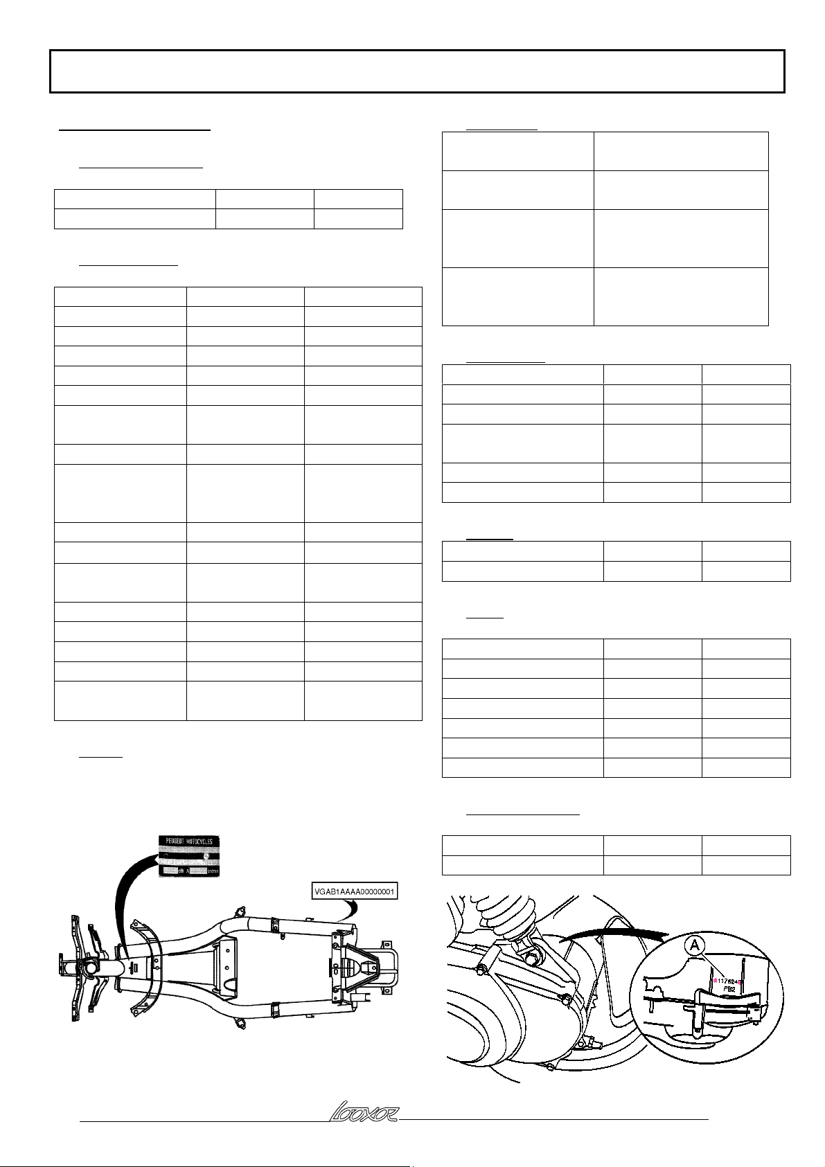
Frame
1- Manufacturer's plate
2- VIN number
rpm
Capacities
Fuel tank 8 litres
unleaded 95 or 98
Oil tank 1.2 litres
semi-synthetic oil
Relay box 0.12 litres
SAE 80W90 oil
Life lubricated
Fork 2 X 0.11 litres
Esso Univis 46
Agip H Lift 46
Dimensions
50cc 100cc
Length 1925 mm 1925 mm
Width 716 mm 716 mm
Height without rear
1126 mm 1126 mm
view mirror
Ground clearance 130 mm 125 mm
Wheelbase 1311 mm 1311 mm
Weight
50cc 100cc
Weight 100 kg 107 kg
Tyres
50cc 100cc
Front wheel 1.85 "x 16" 1.85" x 16"
Front tyre 80/80-16 80/80-16
Front pressure 1.8 bar 1.8 bar
Rear wheel 2.50" x 16" 2.50" x 16"
Rear tyre 100/70-16 100/70-16
Rear pressure 2 bar 2 bar
Engine markings
Engine type FC1-FC3 FC2
Reproduction or translation, even partial, are forbidden without the written consent of Peugeot Motocycles
50cc 100cc
Page: 4
Page 5
SERVICE SCHEDULE AND COMMISSIONING
SERVICE SCHEDULE AND COMMISSIONING
Heavy duty servicing is aimed at machines used under "harsh" conditions: door-to-door deliveries, intensive
urban use (courier), short trips with cold engine, dusty regions, ambient temperature of over 30°c.
Service operation 500 kms
or 1 month
Every 5000 kms
or 12 months
Every 10000 kms
Harsh conditions 500 kms Every 2500 kms Every 5000 kms
Check:
Idle speed X X X
Throttle control X X X
Oil pump operation * X X X
Functioning of electrical equipment X X X
Front and rear brake operation * X X X
Fuel pipe X X X
Oil pipe X X X
Front brake fluid pipe X X X
Tyre pressures X
Tyre condition, pressure and wear X X
Brake fluid level X X X
Battery electrolyte level * X X X
Tightness of nuts and bolts X X X
Change:
Spark plug X X
Inlet silencer filter element X X
Front brake pad # X
Rear brake pad * # X
Rear brake lining * #
Drive pulley bushes # X X
Transmission belt X
Check and decarbonize:
Piston X
Cylinder head X
Exhaust port X
Check and grease:
Idle flange pulley and needle bushes X
Drive pulley: idle flange and rollers * X
Kickstart drive gear and shaft bush X
Clean and set:
Carburettor X
Test the machine:
On the road X X X
* depending on equipment
# if necessary
Reproduction or translation, even partial, are forbidden without the written consent of Peugeot Motocycles
Page: 5
Page 6
SERVICE SCHEDULE AND COMMISSIONING
Battery preparation (unless maintenance-free battery)
Remove the battery
Remove the 6 filler caps and the vent cap
Fill with electrolyte up to the level marked UPPER LEVEL
Electrolyte: (35% sulphuric acid = 1.28g/cm3) 1 litre P/N: 752740, 5 litres P/N: 752741
Leave the battery to stand for approximately half an hour
Top up again if necessary
Charge the battery for at least 2 hours with a current of 400mA (0.4A)
Refit the battery and connect the vent pipe
Connect terminal with the red wires to the + and the terminal with the green wire to the -.
Then the battery should be topped up again if necessary, after fully charging, using distilled water only
Filling the fuel and oil systems
Put in the tank 1 litre of 95 or 98 unleaded fuel mixed with 3 % of 2-stroke semi-synthetic oil
Top up the oil with 2-stroke semi-synthetic oil
Start the engine and disconnect the oil feed pipe to the carburettor on the 50 cc model and to the inlet pipe on
the 100 cc model, that the oil is supplied in drops (the frequency of the drops increases with engine speed)
Top up the tank with pure fuel only
Checks before handing over to customer
Check tightness of wheel nuts
Front wheel: 6 m.daN
Rear wheel 10 m.daN
Check all nuts and bolts are tight
Check brake adjustment and efficiency
Check tyre pressures cold
Front wheel: 1.8 bar
Rear wheel 2 bar
Check operation of lighting, direction indicators, horn, and brake light
Check operation of the different warning lights
Carry out a road test
Reproduction or translation, even partial, are forbidden without the written consent of Peugeot Motocycles
Page: 6
Page 7

SPECIAL IMPORTANT POINTS
SPECIAL IMPORTANT POINTS
Tyres:
This machine is fitted with special tyres manufactured by Hutchinson. When replacing tyres, it is essential to
fit tyres of the same type and same dimensions
To open the saddle:
The saddle on this machine is opened electrically. This is carried out by turning the ignition key fully to the
right
When the saddle opens, the ignition key automatically returns to the ignition on position
Important do not forget to turn off the ignition after opening the saddle
Oil and fuel:
This machine is designed to run on unleaded 95 or 98 fuel
The oil to use for separate lubrication is semi-synthetic oil
Reproduction or translation, even partial, are forbidden without the written consent of Peugeot Motocycles
Page: 7
Page 8
TIGHTENING TORQUES AND SPECIAL TOOLS
N
N
N
N
N
N
N
N
N
N
N
N
N
N
N
N
N
N
N
N
N
N
N
N
N
N
N
N
N
N
N
N
N
N
TIGHTENING TORQUES AND SPECIAL TOOLS
Tightening torques
Body panels:
Main fairings 0,4 m.da
Foot panel 0,4 m.da
Speedo cover 0,1 m.da
Saddle locker 0,6 m.da
Legshield panel front 0,1 m.da
Legshield panel rear 0,1 m.da
Engine side panels 0,1 m.da
Front mudguard 0,8 m.da
Rear mudguard * 0,8/0,1 m.da
Mudflap * 0,8/0,1 m.da
Grab handle 1,2 m.da
Steering lock 0,6 m.da
Saddle opening control 0,1 m.da
Frame:
Front wheel spindle nut 6 m.da
Rear wheel spindle nut 10 m.da
Linkrod engine pivot 5,2 m.da
Frame engine pivot 5,2 m.da
Shock absorber upper mount 4,3 m.da
Shock absorber lower mount 2 m.da
Exhaust nut on cylinder 1,5 m.da
Exhaust nut on engine 2 m.da
Top cone 3,8 m.da
Top cone locknut 2,1 m.da
Steering locknut 7 m.da
Front brake caliper 2,5 m.da
Rear brake caliper 2,5 m.da
Front brake disc 1 m.da
Rear brake disc 1 m.da
Stand on engine 1,9 m.da
Standard:
Screw and nut diameter 5 mm 0,5 m.da
Screw and nut diameter 6mm 1 m.da
Screw and nut diameter 8mm 2,2 m.da
Screw and nut diameter 10mm 3,5 m.da
Screw and nut diameter 12mm 5,5 m.da
Special tools:
Description Part Number
Steering column wrench 754086
* depending on size of screw
Reproduction or translation, even partial, are forbidden without the written consent of Peugeot Motocycles
Page: 8
Page 9
BODY PANELS
BODY PANELS
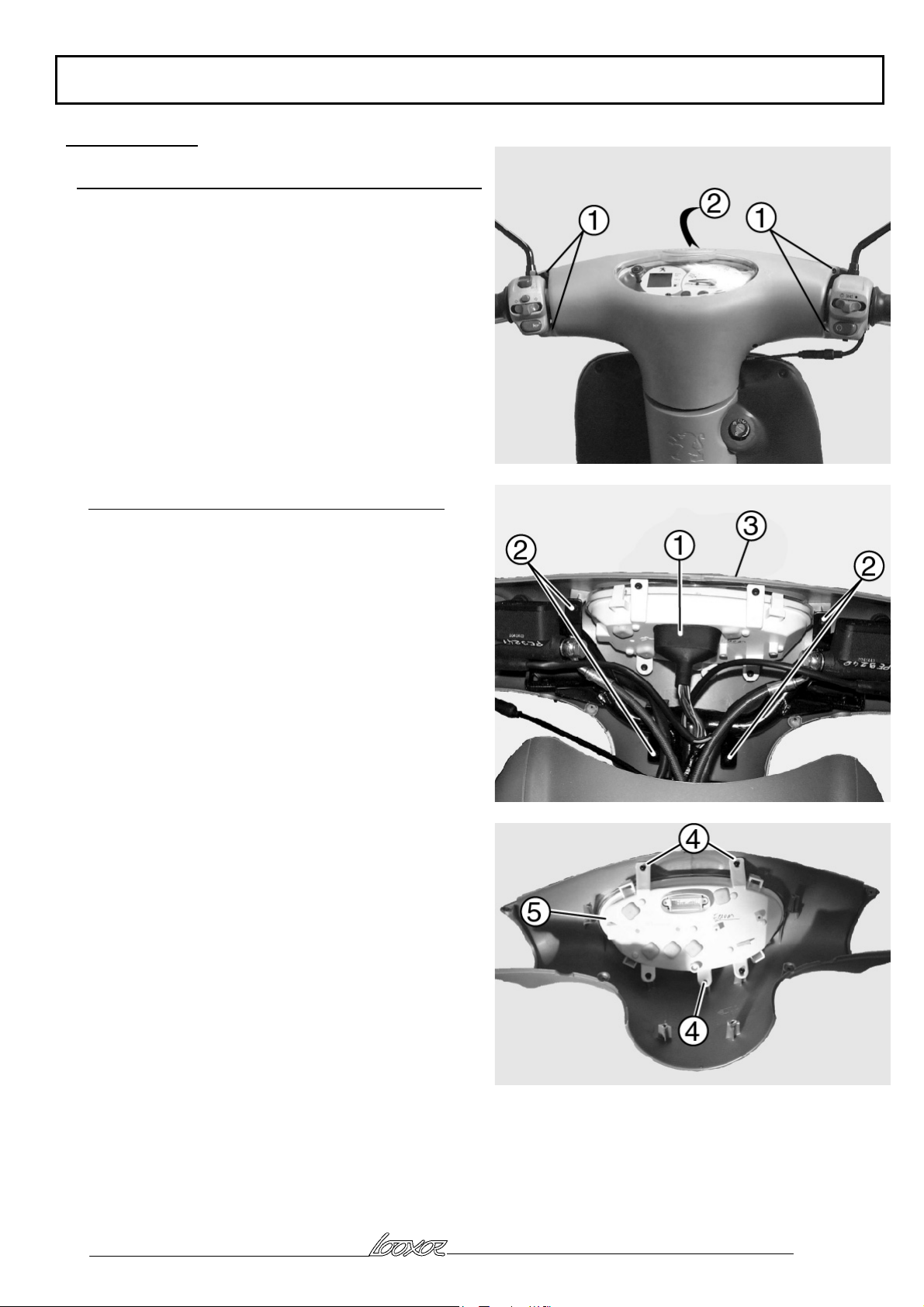
Removal of instrument panel upper cover Operation 1
Remove the 4 screws (1)
Remove the instrument panel upper cover (2)
Removal of instrument panel cover Operation 2
Remove the instrument panel upper cover (see
operation 1)
Disconnect the instrument panel connector (1)
Remove the handlebar 4 fixing screws (2)
Remove the cover (3) and instrument panel assembly
Remove the 3 screws (4) fixing the instrument panel to
the cover
Remove the instrument panel (5)
Reproduction or translation, even partial, are forbidden without the written consent of Peugeot Motocycles
Page: 9
Page 10
BODY PANELS
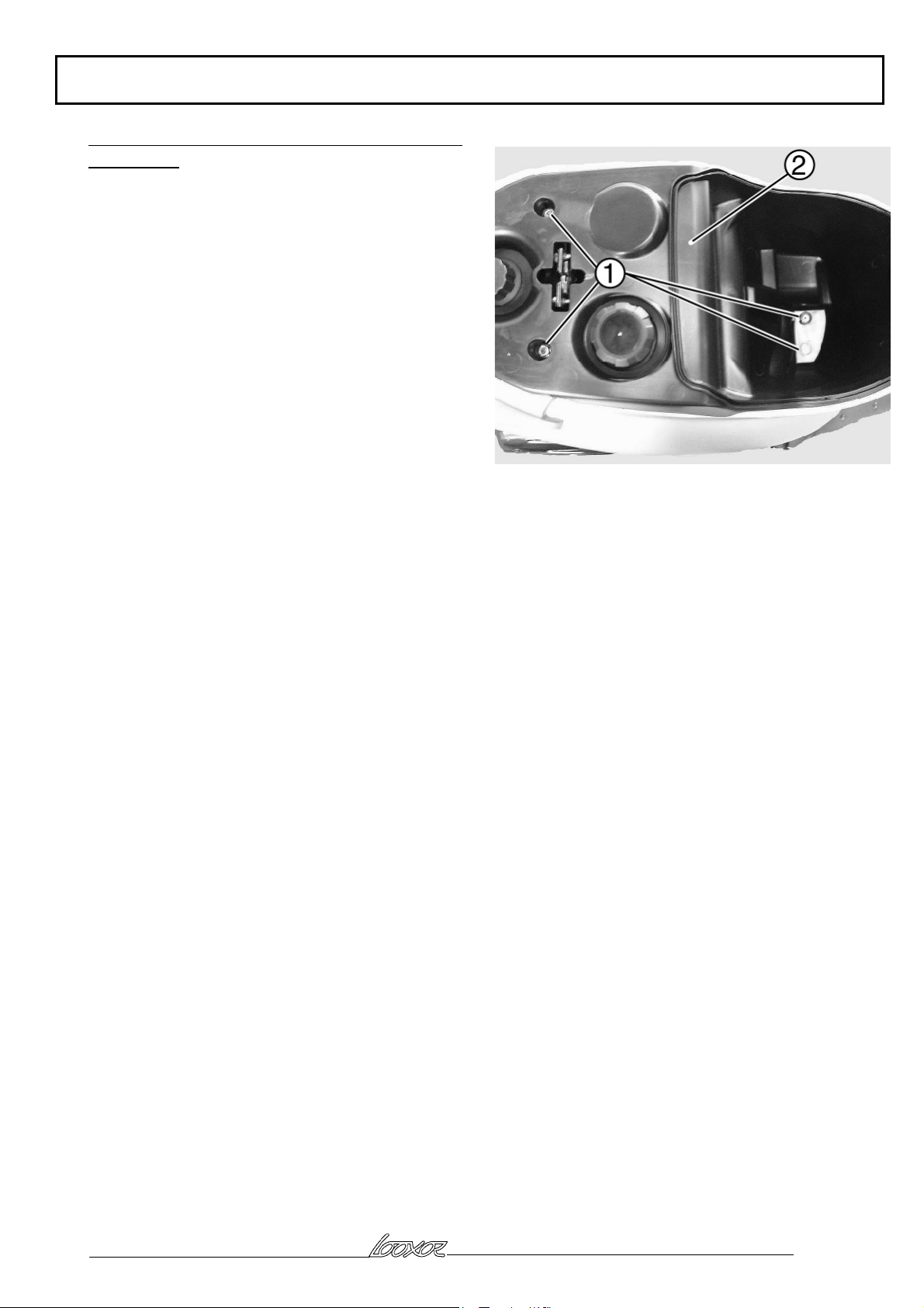
Removal of saddle/storage compartment assembly
Operation 3
Remove the 4 fixing nuts (1)
Withdraw the saddle/storage compartment assembly
(2)
Reproduction or translation, even partial, are forbidden without the written consent of Peugeot Motocycles
Page: 10
Page 11
BODY PANELS
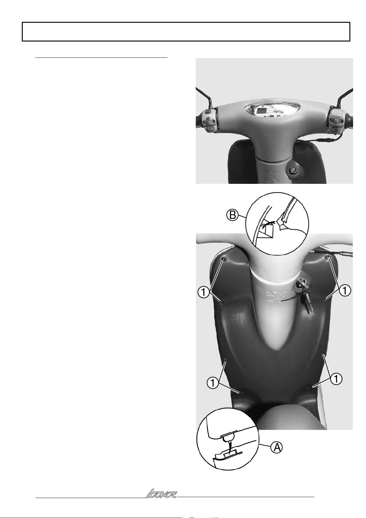
Removal of legshield rear panel Operation 4
Remove the instrument panel upper cover (see
operation 1)
Remove the ignition key
Remove the legshield rear panel 8 screws (1)
Separate the legshield front and rear panels
Unclip the legshield rear panel, from the footboard at
(A), and the two guides in the legshield front panel at
(B)
Withdraw the legshield rear panel from the right hand
side of the machine, by pivoting it downwards
Reproduction or translation, even partial, are forbidden without the written consent of Peugeot Motocycles
Page: 11
Page 12
BODY PANELS
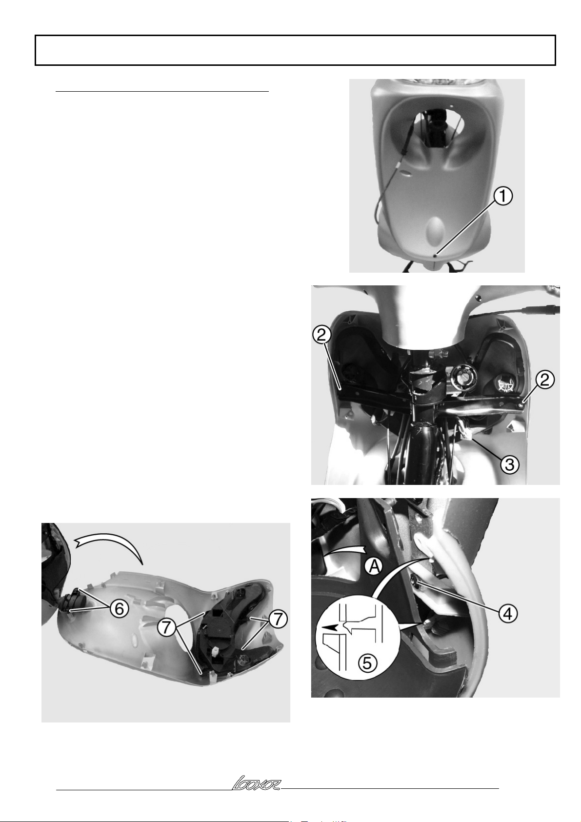
Removal of legshield front panel Operation 5
Remove the legshield rear panel (see operation 4)
Remove the fork (see operation 9)
Remove the screw (1) fixing the legshield front panel
to the main fairings
Remove the 2 upper screws (2) fixing the legshield
front panel to the frame
Disconnect the headlight connector (3)
Remove the 2 lower screws (4) fixing the legshield
front panel to the frame by pushing the footboard lug
(A) to one side
Unclip the 4 points (5) securing the legshield front
panel to the main fairings
Tilt the legshield front panel forwards
Remove the 2 screws (6) fixing the ACI 100 ignition
module, disconnect and remove the module
Remove the 4 screws (7) fixing the headlight and
remove it
Reproduction or translation, even partial, are forbidden without the written consent of Peugeot Motocycles
Page: 12
Page 13
BODY PANELS
Removal of rear RH and LH covers
Operation 6
Remove the saddle/storage compartment assembly (see
operation 3)
Remove the grab handle (2 nuts (1A) and 1 screw
(1B))
Remove the battery cover (1 screw)
Remove the 2 side screws (2)
Remove the screw (3) under the battery cover
Remove the plastic rivet (4) over the battery cover
Disconnect the number plate lighting harness (5)
(100cc)
Remove the rear mudflap 4 screws (6)
Reproduction or translation, even partial, are forbidden without the written consent of Peugeot Motocycles
Page: 13
Page 14
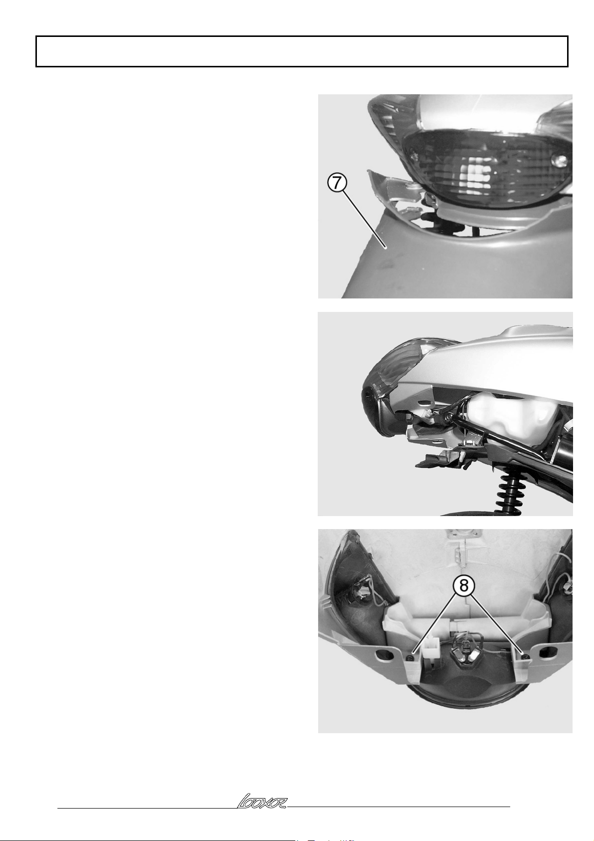
Unclip and remove the rear mudflap (7)
Pull the rear cover assembly towards the rear
Disconnect the rear light
Remove the rear cover assembly
BODY PANELS
Remove the complete rear light (2 screws (8))
Reproduction or translation, even partial, are forbidden without the written consent of Peugeot Motocycles
Page: 14
Page 15
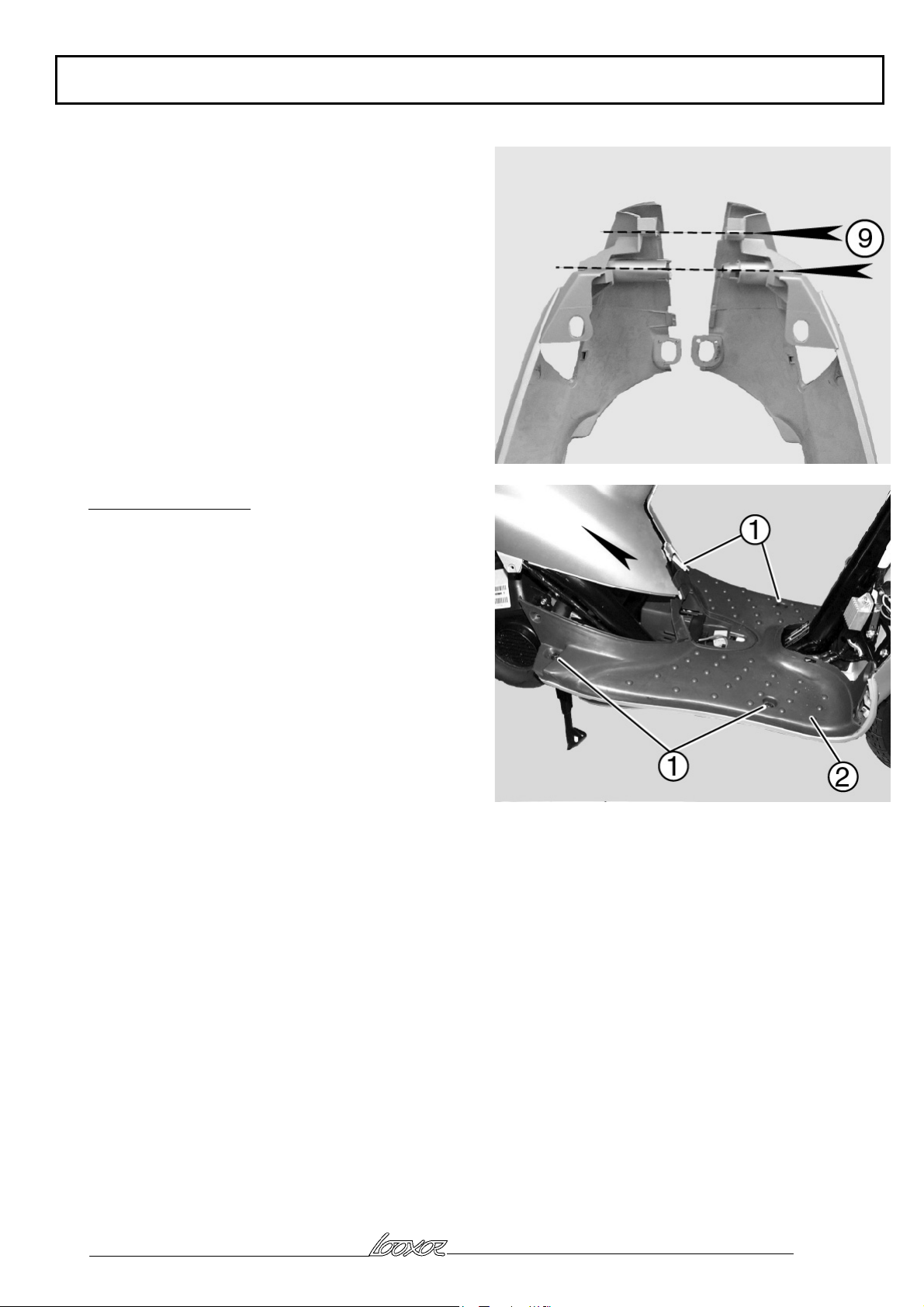
Remove the rear cover assembly 2 screws (9)
Unclip the covers
Removal of footboard
BODY PANELS
Remove the legshield rear panel (see operation 4)
Draw back the rear cover assembly (see operation 6)
Disconnect the battery + terminal
Remove the battery, disconnect the battery - terminal
Remove the footboard 4 fixing screws (1)
Unclip fuse holder and the starter motor relay
Remove the footboard (2)
Reproduction or translation, even partial, are forbidden without the written consent of Peugeot Motocycles
Page: 15
Page 16

BODY PANELS
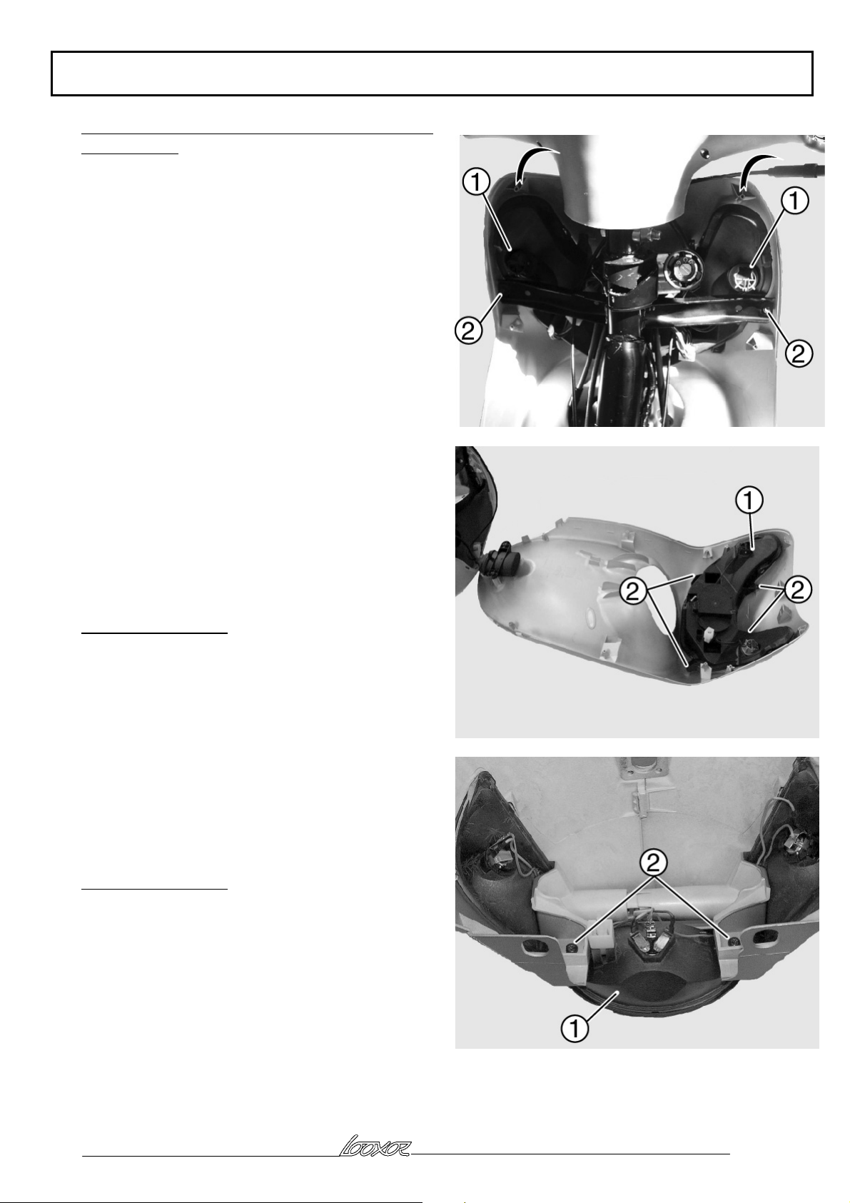
Removal of main fairings Operation 7
Remove the legshield rear panel (see operation 4)
Remove the footboard 4 screws (1)
Remove the lower screw (2) fixing the legshield to the
main fairings
Remove the two screws (3) fixing the main fairings to
the legshield front panel by holding apart the main
fairing clip (A)
Unclip the 4 points (4) securing the main fairings to
the legshield
Raise one side of the footboard, to release the clips (5)
securing the main fairing to the frame
Proceed in the same way for the other side
Remove the main fairing
Reproduction or translation, even partial, are forbidden without the written consent of Peugeot Motocycles
Page: 16
Page 17

BODY PANELS
, The main fairings are joined together by 2 screws
lengthways and a clip system at the front
, Check the two main fairings are properly joined at
(B) before fitting
Position the main fairings fitted to the frame lugs
under the footboard
Clip the 4 securing points to the legshield front panel
Fit the legshield front panel lower screw first
Complete assembly by inserting the two lower screws
on the legshield front panel
Then fit the footboard 4 screws
Removal of front mudguard
Remove the front fork (see operation 9)
Remove the front mudguard 3 screws (1)
Remove the front mudguard (2)
Reproduction or translation, even partial, are forbidden without the written consent of Peugeot Motocycles
Page: 17
Page 18

BODY PANELS
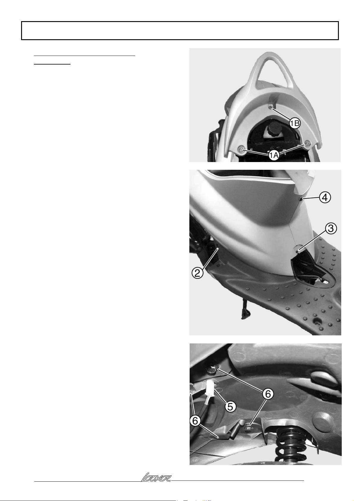
Removal of rear mudguard and the mud flap
Operation 8
Remove of the saddle/storage compartment assembly
(see operation 3)
Remove the battery cover (1 screw)
From the rear covers remove the screw and the plastic
rivet over the battery cover and the 2 side screws
Remove grab handle (2 nuts (1A) and one screw (1B))
Remove the rear mudflap 4 screws (2)
Disconnect the number plate light connector (3)
Remove the rear mudflap (4)
Reproduction or translation, even partial, are forbidden without the written consent of Peugeot Motocycles
Page: 18
Page 19

BODY PANELS
Remove the mudguard (5) (1 centre screw (6) and 2
side screws (7))
Reproduction or translation, even partial, are forbidden without the written consent of Peugeot Motocycles
Page: 19
Page 20
BODY PANELS
Removal of headlight, sidelight, and front direction
indicator bulb
Remove the legshield rear panel (see operation 4)
, This gives access to the direction indicator bulbs
(1)
Remove the 2 upper screws (2) from the legshield
front panel
, Tilt the legshield front panel forwards to access
the headlight and sidelight bulbs
Remove headlight cover
Unclip the headlight bulb holder
Remove the bulb
, The bulb holder has a locator for fitting to the
headlight
To release the sidelight bulb holder press on the bulb
holder tabs and remove it
Removal of headlight
The front direction indicators are built into the
headlight
Remove the legshield front panel (see operation 5)
Remove the headlight (1), 4 screws (2)
Removal of rear light
Remove the RH and LH rear covers (see operation 6)
Remove the rear light (1), 2 screws (2)
Reproduction or translation, even partial, are forbidden without the written consent of Peugeot Motocycles
Page: 20
Page 21

FRAME
FRAME
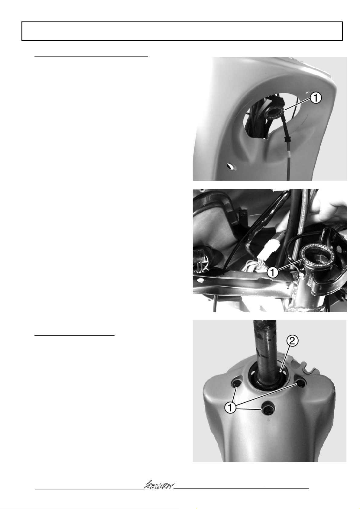
Removal of fork Operation 9
Remove the legshield rear panel (see operation 4)
Slacken the front wheel spindle nut
Remove the front brake caliper 2 screws
Hang the front caliper from the machine without
disconnecting it
Remove the handlebar to pivot tube screw and nut (1)
Unclip the antenna (2) in order not to damage it
Protect the legshield front panel and tilt the handlebar
forward
Remove the front wheel
Disconnect the speed sensor 3-pin connector (3)
Remove the steering nut (4) and its shimming use tool
P/N: 754086
Remove the fork (5)
, there is a ball-bearing cage at the top of the
steering head (6) (no special fitting position) and at the
bottom 21 balls of Ø6.4mm
Reproduction or translation, even partial, are forbidden without the written consent of Peugeot Motocycles
Page: 21
Page 22
FRAME
Removal of fork lower and upper races
Remove the fork (see operation 9)
Drift out the races (1)
, The races must be changed every time they are
removed
Removal of fork lower cone
Remove the fork (see operation 9)
Remove the front mudguard (3 screws (1))
Drift out the cone (2)
Reproduction or translation, even partial, are forbidden without the written consent of Peugeot Motocycles
Page: 22
Page 23

Dismantling the fork
Removal of fork stanchions
Remove the fork (see operation 9)
Remove the end plugs (1) from the stanchions (2)
, The end plugs are fitted with a sealing washer
which must be changed each time it is removed.
Drain the oil from the stanchions
Operate the stanchions several times to completely
drain off all the oil
Remove the stanchions
Removal of seals
Remove the dust cover (3)
Remove the circlips (4)
Remove the seal (5)
Remove the compression limit cone (6)
FRAME
, After changing the dust covers, the circlips, and
the seals, pour into the fork tubes fork 110 cc of oil for
the 100 cc model and 70 cc of oil for the 50cc model.
Insert the stanchions into the tubes and refit the end
plugs with new seals
Oil Esso Univis 46 P/N: 754697 for 5-litre can
Or Agip H Lift 46
Reproduction or translation, even partial, are forbidden without the written consent of Peugeot Motocycles
Page: 23
Page 24

FRAME
Removal of steering lock
Remove the legshield rear panel (see operation 4)
Unclip the lock antenna (1) (100cc)
Disconnect the lock connector (2)
Remove the lock shear screw with a punch (3)
Remove the lock (4)
, For the 100cc if the steering lock is to be changed,
the transponder (5) in the master key (red) must be
retained and reinstalled in the new master key. Then
the key learning program must be carried out (see SI
N° 96)
Removal of rear brake hose
Remove the legshield rear panel (see operation 4)
Remove the main fairing (see operation 7)
Open the brake fluid reservoir (1)
Connect a tube leading into a jar to the rear caliper
bleed screw
Operate the brake lever to drain the circuit
Remove the banjo bolts (4) and (5) from the caliper
and the master cylinder
Unhook the brake hose (6) at the stand at (A)
Remove the brake hose (6)
After refitting, bleed the circuit (see bleed operation in
Manuals and Methods document N°10)
Reproduction or translation, even partial, are forbidden without the written consent of Peugeot Motocycles
Page: 24
Page 25

MISCELLANEOUS WORK
MISCELLANEOUS OPERATIONS
Removal of handlebar
Remove the instrument panel cover (see operation 1)
Remove the legshield rear panel (see operation 4)
Remove the RH and LH control switch modules (2
screws each)
Make an alignment mark at (A) (in rotation and
longitudinally) on the front and rear brake master
cylinders and remove them (2 screws each)
Remove the RH grip (2 screws (1))
Release the throttle control (2) by turning it ¼ turn
, If the position of the master cylinders has not been
marked position them at 12mm from the control switch
modules in a standard operating position. The control
switch modules are indexed to the handlebar
Unclip the steering lock antenna (3) (100cc)
Remove the screw and nut (4) securing the handlebar
to the pivot tube
Remove the handlebar (5)
Reproduction or translation, even partial, are forbidden without the written consent of Peugeot Motocycles
Page: 25
Page 26

MISCELLANEOUS WORK
Removal of RH and LH control switch modules
Remove the legshield rear panel (see operation 4)
Disconnect the control switch module connector
involved from the main harness
Remove the control switch module, 2 screws
, The control switch modules are indexed to the
handlebar
Removal of throttle and oil controls
Remove the legshield rear panel (see operation 4)
Remove the main fairing (see operation 7)
Removal of saddle/storage compartment assembly
Remove the air intake (1 screw)
Remove the air filter module (2 screws)
Remove the RH grip (2 screws (1) )
Release the throttle control cable (2) by turning it ¼ of
a turn.
Remove the oil pump cable (3)
Remove the carburettor chamber top (4)
Remove the slide valve
Unclip the control cable from the frame under the
footboard
Remove the control cable
Reproduction or translation, even partial, are forbidden without the written consent of Peugeot Motocycles
Page: 26
Page 27

MISCELLANEOUS WORK
Removal of exhaust Operation 10
Remove the saddle/storage compartment assembly (see
operation 3)
Remove the air intake (2) screw (1) and push it slightly
away
Remove the 2 exhaust nuts (3) from the cylinder end
Remove the exhaust trim, 3 screws
Remove the exhaust 3 fixing screws (4)
The 2 screws (4A) are coated with locking compound
and therefore must be replaced each time they are
removed
Reproduction or translation, even partial, are forbidden without the written consent of Peugeot Motocycles
Page: 27
Page 28

MISCELLANEOUS WORK
Removal of saddle opening control
Remove the rear RH and LH covers (see operation 6)
Remove the oil tank (see operation 12)
Disconnect the opening control connector (1)
Unhook the lock control linkage (2)
Remove the opening control fixing screw (3)
Unhook the opening control (4) from the frame and
remove it
Reproduction or translation, even partial, are forbidden without the written consent of Peugeot Motocycles
Page: 28
Page 29
MISCELLANEOUS WORK
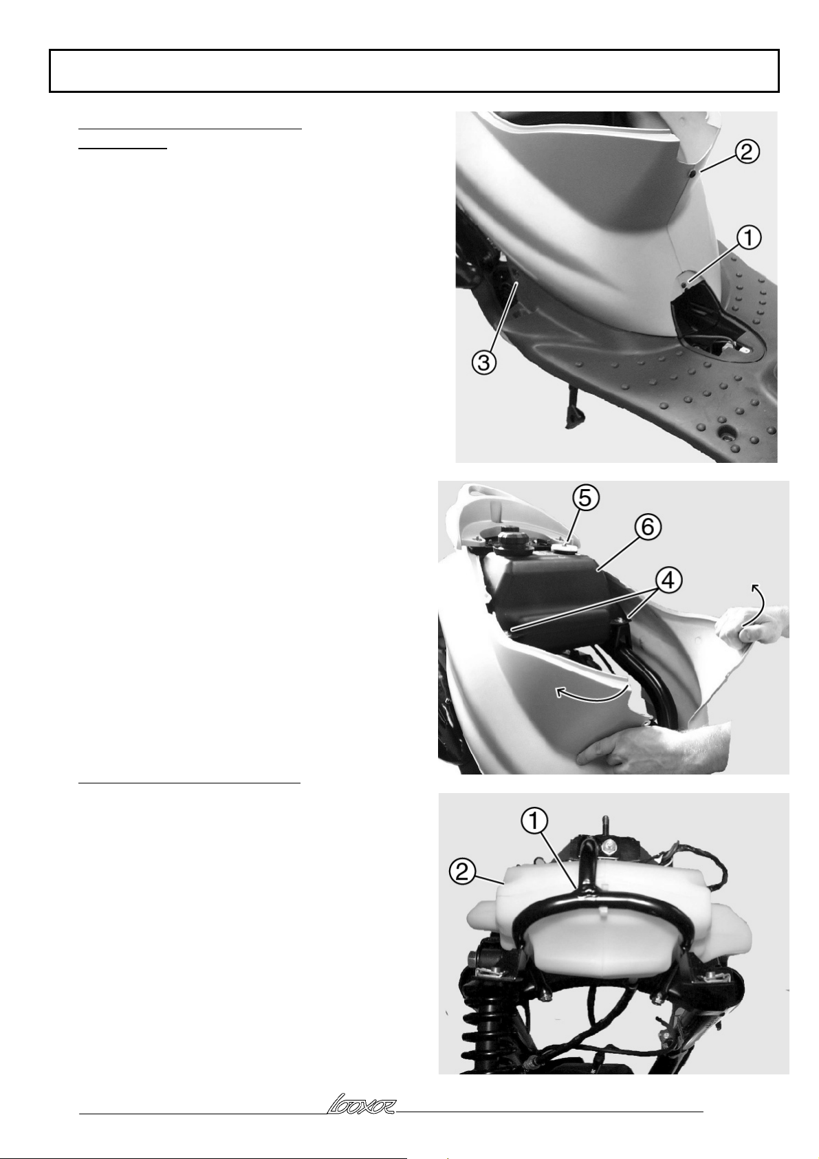
Removal of fuel tank and its valve
Operation 11
Remove the saddle/storage compartment assembly (see
operation 3)
Remove the battery cover
Remove the screw (1) and the plastic rivet (2) over the
battery cover
Remove the side cover 2 screws (3)
Open out the side covers above the battery
Remove the fuel tank 2 fixing nuts (4) and the two
washers
Disconnect the fuel gauge (5)
Remove the fuel tank (6)
Disconnect the fuel valve
, Note the position of the valve in relation to the
tank before removing it
Removal of oil tank Operation 12
, The oil gauge cannot be removed
Remove the rear RH and LH covers (see operation 6)
without removing the rear light
Remove the oil tank bracket (1), 3 screws
Disconnect the oil dipstick
Disconnect the oil pipe
Remove the oil tank (2)
, The oil pump circuit must be bled each time
work is carried out on the lubrication system (see
relevant engine workshop manual)
Reproduction or translation, even partial, are forbidden without the written consent of Peugeot Motocycles
Page: 29
Page 30

MISCELLANEOUS WORK
Removal of oil pipes
Removal of pipe between tank and pump
Remove the exhaust (see operation 10)
Remove the fuel tank (see operation 11)
Remove the engine air intake (1 screw)
Remove the oil pump tension bracket (1)
Disconnect the pipe (2)
Drain the oil tank
Remove the rear mudguard and mudflap (see
operation 8)
Remove the assembly, filter tank pipe (3) /filter (4)
/oil pump filter pipe (2)
, On reassembly, before connecting the pipe, put
a little oil in the tank and let the pipes and filter fill
up
Removal of pipe between the oil pump and inlet
pipe (100cc) or carburettor (50cc)
Remove the exhaust al of the exhaust (see
operation 10)
Remove the engine air intake (1 screw) (50cc)
Remove the oil pump tension bracket (1)
Disconnect the pipe (5)
Reproduction or translation, even partial, are forbidden without the written consent of Peugeot Motocycles
Page: 30
Page 31
MISCELLANEOUS WORK
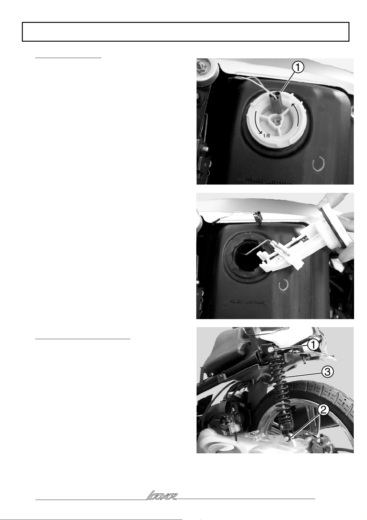
Removal of fuel gauge
Remove the saddle/storage compartment assembly (see
operation 3)
Disconnect the fuel gauge connector (1)
Turn the gauge 1/8 of a turn towards the left
Remove the gauge
Removal of rear shock absorber
Remove the rear RH and LH cover assembly (see
operation 6)
Remove the air filter module air, 2 screws
Remove the shock absorber upper fixing bolt (1)
Remove the shock absorber lower fixing bolt (2)
Remove the shock absorber (3)
Reproduction or translation, even partial, are forbidden without the written consent of Peugeot Motocycles
Page: 31
Page 32

WORK ON THE ENGINE WITHOUT REMOVING THE ENGINE
WORK ON THE ENGINE WITHOUT
REMOVING THE ENGINE
Removal of magneto coil
Remove the legshield rear panel (see operation 4)
Remove the exhaust pipe (see operation 10)
Remove the main fairing (see operation 7)
Disconnect the coil connector (1) from the main
harness (in the main fairing)
Remove the cooling volute, the magneto rotor, and the
coil, see relevant engine workshop manual
Removal of starter motor
Remove the legshield rear panel (see operation 4)
Remove the main fairing (see operation 5)
Disconnect starter motor connector (2) from the main
harness (in the main fairing)
Remove the starter motor 2 screws (3)
Remove the starter motor (4)
Removal of carburettor
Remove the legshield rear panel (see operation 4)
Remove the main fairing (see operation 7)
Remove the air filter module, 2 screws
Remove the air filter air intake
Disconnect the fuel (1) and vacuum (2) pipes Make a
note of the position of each pipe
Disconnect the choke connector from the main harness
(in the main fairing)
Remove the rubber sleeve (3)
Disconnect the throttle control, 1 screw (4)
Slacken the clip (5)
Remove the carburettor (6)
Reproduction or translation, even partial, are forbidden without the written consent of Peugeot Motocycles
Page: 32
Page 33

WORK ON THE ENGINE WITHOUT REMOVING THE ENGINE
Removal of cylinder and the piston
Remove the fuel tank (see operation 11)
Remove the exhaust (see operation 10)
Remove the cylinder outer casing (1), 4 screws
Remove the spark plug
To remove the cylinder head, the cylinder, the piston,
see the relevant engine workshop manual
Removal of inlet manifold and valves
Remove the fuel tank (see operation 11)
Remove the exhaust (see operation 10)
On the 100cc engine remove the cylinder
Disconnect the oil injection hose (1) (100cc) or
vacuum pickoff (50cc) from the inlet manifold
Remove the 4 screws (2) from the inlet manifold, one
of which is a shear screw on the 50cc model
Remove the inlet manifold and carburettor assembly
(3)
Remove the valves
Removal of oil pump
Remove the exhaust (see operation 10)
Unhook the oil pump control cable (1) (100cc)
Remove the oil pump 2 screws (2)
Remove the pump/tension bracket assembly
Disconnect the oil hoses (3)
, Refitting:
Feed the 2 hoses (3) through protective sleeve (4)
Connect the hoses to the oil pump
Put the oil pump in position
Put the tension bracket (5) in position
Fit the two fixing screws (2)
Fit the control cable to the oil pump (1)
Check the cable adjustment (see relevant workshop
manual)
, The oil pump system must be bled after any
work on the lubrication system
(see relevant engine workshop manual)
Reproduction or translation, even partial, are forbidden without the written consent of Peugeot Motocycles
Page: 33
Page 34
WORK ON THE ENGINE WITHOUT REMOVING THE ENGINE
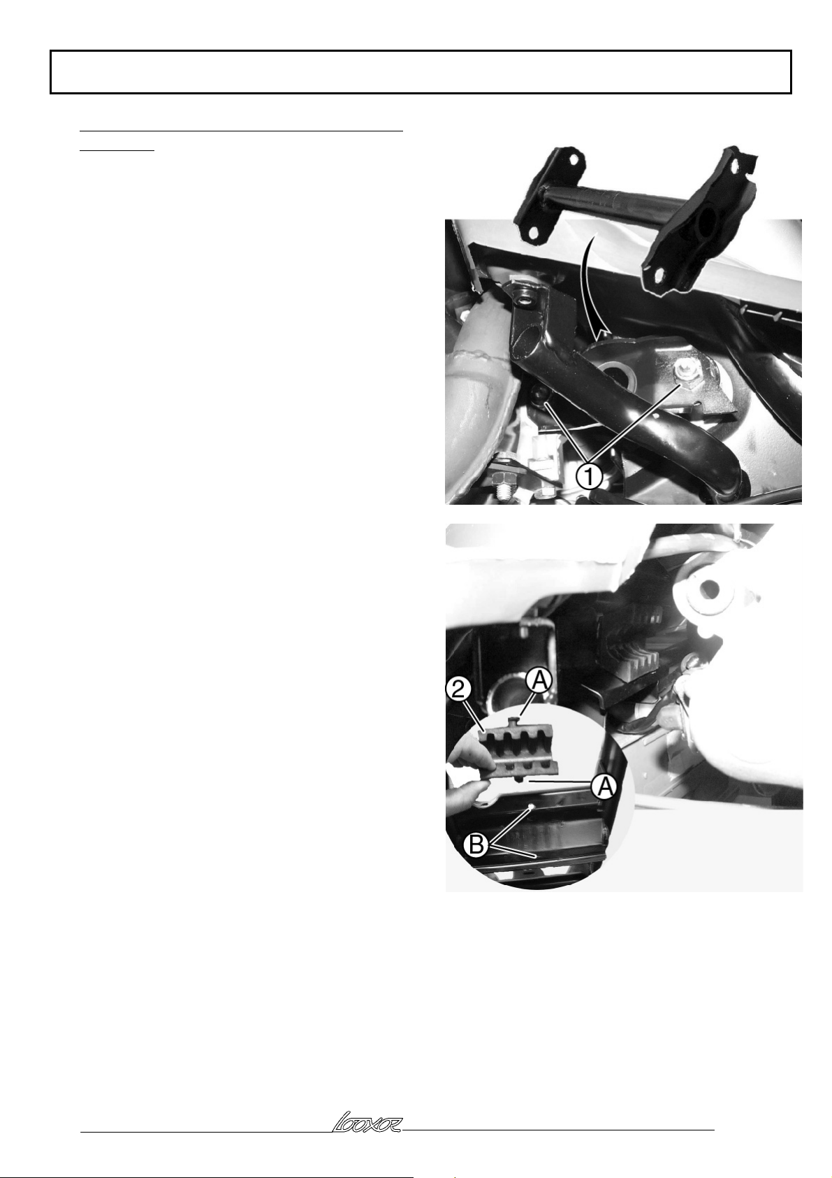
Removal of engine mounting linkrod and rubber
thrust bush
Remove the saddle/storage compartment assembly (see
operation 3)
Remove the legshield rear panel (see operation 4)
Remove the main fairing (see operation 7)
Remove the engine mounting linkrod 2 nuts (1)
Suspend the machine
Remove the 2 engine mounting linkrod shafts
Remove the engine mounting linkrod from the top
, On reassembly, check the rubber bush (2) is
correctly positioned in the frame. The 2 rubber locators
(A) must be inserted in the 2 locating holes (B) in the
frame
Reproduction or translation, even partial, are forbidden without the written consent of Peugeot Motocycles
Page: 34
Page 35
ELECTRICITY
ELECTRICITY
Removal of ACI 100 ignition module (100cc)
Remove the main fairing (see operation 7)
Remove the ACI 100 ignition module , 2 screws (1)
Disconnect the ACI 100 ignition module
Removal of transponder antenna (100cc)
Remove the legshield rear panel (see operation 4)
Remove the main fairing (see operation 7)
Remove the ACI 100 ignition module , 2 screws
Disconnect the transponder antenna
Unclip the transponder antenna (1) from the steering
lock
Remove the transponder antenna
Removal of high tension coil
Remove the fuel tank (see operation 11)
Disconnect the 2 wires (1)
Remove the high tension coil, 1 screw (2)
Reproduction or translation, even partial, are forbidden without the written consent of Peugeot Motocycles
Page: 35
Page 36

ELECTRICITY
Removal of voltage regulator
Removal of horn
Removal of lighting and choke resistors
Remove the legshield rear panel (see operation 4)
The voltage regulator, horn and resistors are fixed to
the frame
Removal of CDI ignition module (50cc)
Remove the legshield rear panel (see operation 4)
Remove the CDI module (1)
Reproduction or translation, even partial, are forbidden without the written consent of Peugeot Motocycles
Page: 36
Page 37

ELECTRICITY
Removal of instrument panel
Remove the instrument panel cover (see operation 2)
Remove the instrument panel 3 screws (1) fixing it to
the cover
Removal of speed sensor
Remove the legshield rear panel (see operation 4)
Disconnect the speed sensor connector (1) from the
main harness
Remove the front wheel (2)
Remove the speed sensor and its cable (3)
Reproduction or translation, even partial, are forbidden without the written consent of Peugeot Motocycles
Page: 37
Page 38
ELECTRICITY
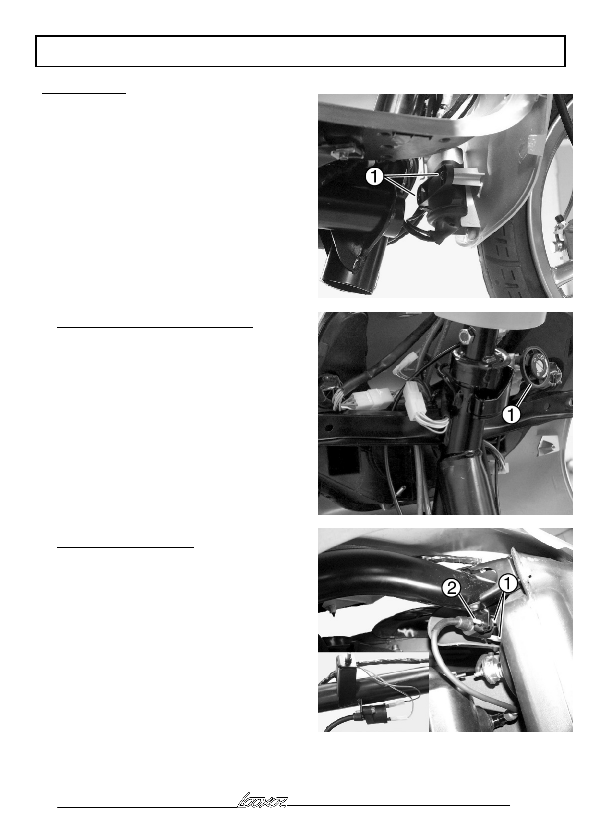
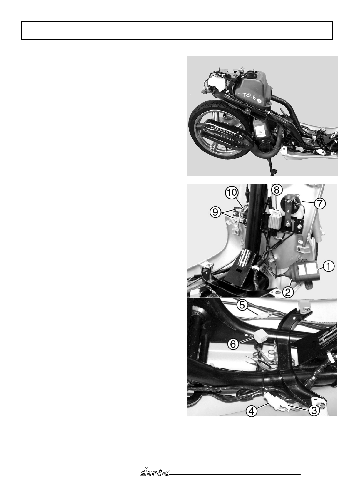
Removal of main harness
Remove the rear RH and LH covers (see operation 6)
Remove the battery
Disconnect: the fuel gauge, the oil gauge, the saddle
opening control, the high tension coil
Remove the footboard (4 screws)
Remove the ACI 100 module (1), 2 screws (100cc)
Disconnect the ACI 100 module
Remove the protective rubber cap (2) and disconnect
the antenna (100cc)
Remove the CDI module (50cc)
Disconnect:
- the starter motor connector (3)
- the magneto coil connector (4)
- the choke connector (5)
- the starter motor relay (6)
- the horn (7)
- the regulator (8)
- the lighting and choke resistors (9)
- the resistor earth wires (10)
Reproduction or translation, even partial, are forbidden without the written consent of Peugeot Motocycles
Page: 38
Page 39

ELECTRICITY
Remove the 2 upper screws (11) from the legshield
front panel and tilt it forwards
Remove the legshield fixing bracket (12) on lower RH
side
Disconnect:
- the headlight (13)
- the steering lock (14)
- the speed sensor connector (15)
- the RH and LH control switch module connectors
from the main harness (16)
- the instrument panel
- the brake light switches
Remove the main harness
Reproduction or translation, even partial, are forbidden without the written consent of Peugeot Motocycles
Page: 39
Page 40

REMOVING THE ENGINE
REMOVING THE ENGINE
Removal of power unit
Remove the saddle/storage compartment assembly (see
operation 3)
Remove the legshield rear panel (see operation 4)
Remove the main fairing (see operation 7)
Remove the air filter module 2 screws (1)
Remove the air intake 1 screw (2)
Disconnect the choke control, coil, starter motor,
connectors (3), located under the footboard
On the engine, disconnect the suppressor, the
carburettor throttle cable, the carburettor fuel feed and
vacuum pipes (note the position of each pipe),
disconnect the oil pump cable (100cc)
Slacken the rear wheel nut
On the 100cc model, remove the rear brake caliper
without opening the circuit
On the 50cc model, disconnect the rear brake cable
Remove the nut from the engine mounting linkrod (4)
Slacken the shock absorber lower fixing bolt
Suspend the machine
Remove the engine mounting bolt from the mounting
bracket linkrod and the shock absorber bolt
Move the engine slightly out of the frame
Disconnect the oil pump feed pipe
Reproduction or translation, even partial, are forbidden without the written consent of Peugeot Motocycles
Page: 40
Page 41

REMOVING THE ENGINE
Stripping down the power unit
Remove the exhaust
Remove the rear wheel
Remove the stand
Remove the kickstart pedal
Remove the exhaust third mounting bracket
Remove the carburettor sleeve
Remove the oil hose plastic protective sleeve
, When refitting the power unit, the first operation is
to connect the oil pump pipes (1) (2) which have
already been inserted in the plastic protective sleeve
(3)
Reproduction or translation, even partial, are forbidden without the written consent of Peugeot Motocycles
Page: 41
Page 42

FRAME
FRAME
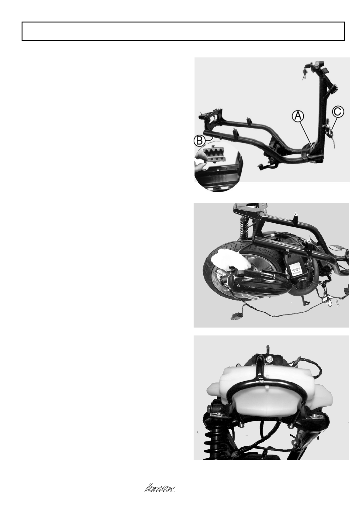
Removal of frame
This method enables changing of the frame only
If a frame is changed following an accident, the
operation must be completed by the repair or
replacement of any other damaged parts
At the rear:
Remove the saddle/storage compartment assembly
Remove the battery cover
Disconnect the battery
Remove the grab handle
Remove the rear mudflap
Remove the rear RH and LH covers
Disconnect the rear light
Disconnect the fuel gauge
Remove the fuel tank
Disconnect the fuel tap
Disconnect the oil low switch
Remove the bracket and oil tank without disconnecting
the pipe
Remove the saddle lock
Remove the saddle opening control
Remove and disconnect the high tension coil
Remove the mudguard
At the front:
Remove the speedo upper cover
Remove the legshield rear panel
Remove the footboard
Remove the main fairing
Unclip the steering lock antenna (100cc)
Remove the handlebar pin from the pivot tube
Tilt the handlebar assembly to the front of the machine
Disconnect the speed sensor from the harness
Remove the front caliper without disconnecting it
Reproduction or translation, even partial, are forbidden without the written consent of Peugeot Motocycles
Page: 42
Page 43

FRAME
Remove the complete fork
Disconnect the headlight
Remove the ACI 100 module without disconnecting it
(100cc)
Remove the legshield front panel
Remove the horn, regulator, resistors and CDI module
(50cc) without disconnecting them
Unclip the harness from the frame and cut the plastic
ties
On the engine:
Remove the engine mounting bracket shaft from the
frame side
Remove the shock absorber upper mount
Remove the frame
Stripping the frame
Remove the manufacturer's plate (A)
Remove the steering lock
Remove the legshield front panel two stiffeners
Remove the mounting bracket clips and rubber
, On the bench, there should be the power unit, the
main harness and its non-disconnected components,
and the handlebar assembly
Reproduction or translation, even partial, are forbidden without the written consent of Peugeot Motocycles
Page: 43
Page 44
FRAME
Refitting the frame
Preparing the frame
Engrave the VIN number at (B)
Refit the manufacturer's plate at (A) (1 rivet)
Fit the lower and upper steering ball races
Fit the steering lock
Fit the linkrod rubber thrust bush
Fit the two legshield front panel stiffeners at (C)
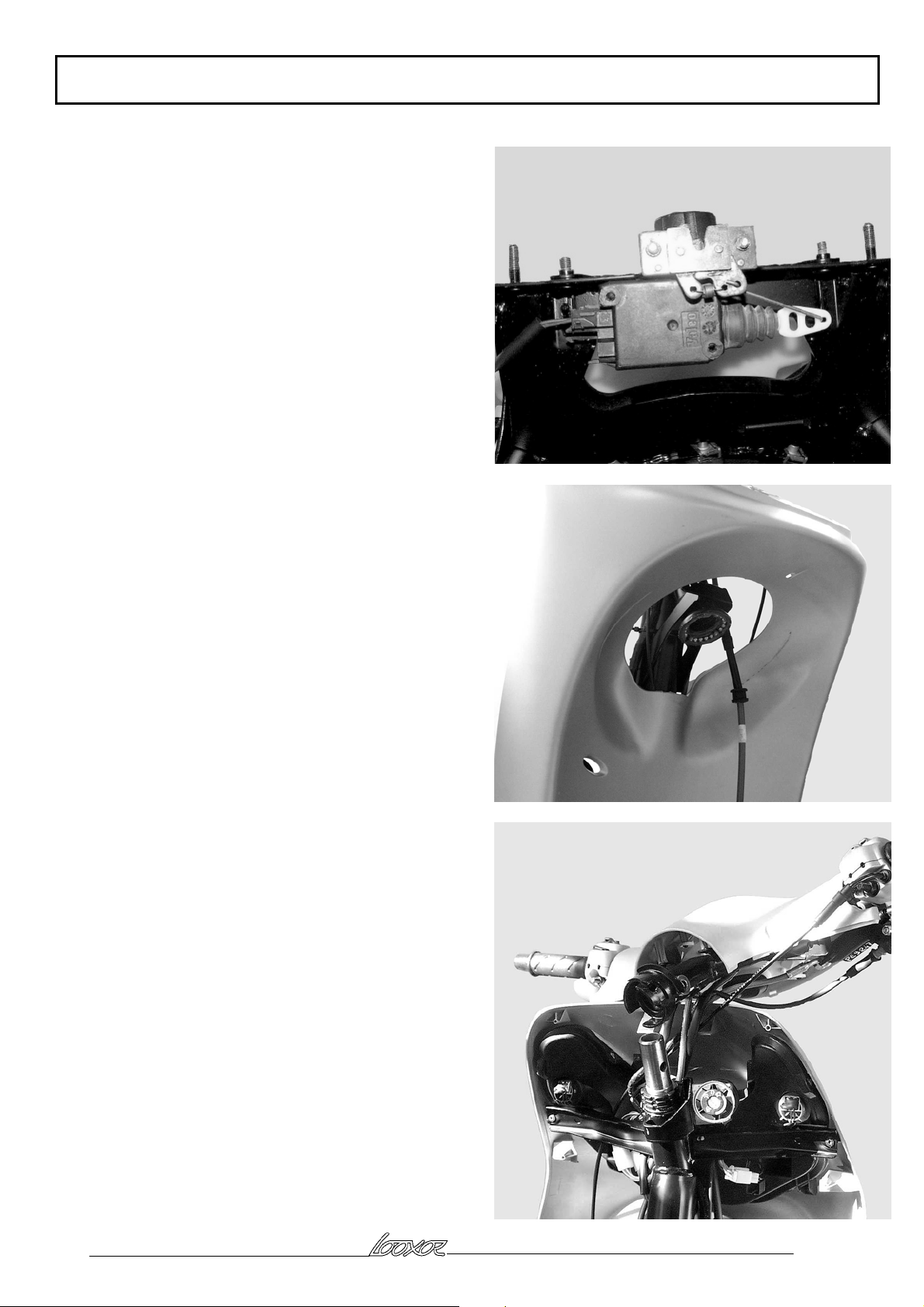
Rear part 1:
Position the frame on the power unit
Position the shaft on the engine mounting linkrod
Position the shock absorber upper mounting shaft
Fit the saddle opening control (1 screw)
Fit the oil tank with its bracket (3 screws)
Connect the oil low switch
Fit and connect the high tension coil (1 screw)
Connect the starter motor and magneto coil connectors
Fix the main harness to the RH side of the frame (clips
and plastic ties)
Front part 1:
Fit the voltage regulator and horn
Fix the brake and throttle cables and also the choke
harness on the LH side of the frame (clips and plastic
ties)
Fit the horn, the regulator, the CDI module (50cc), the
choke and lighting resistors and the earth wire to the
resistor mountings
Connect the choke on the footboard
Reproduction or translation, even partial, are forbidden without the written consent of Peugeot Motocycles
Page: 44
Page 45
FRAME
Rear part 2:
Fit the saddle lock (2 screws)
Fit the saddle lock / open control linkage
Fit the mudguard (1 centre screw and 2 side screws)
Connect the fuel tap and fuel tank overflow pipes
Fit the fuel tank (2 nuts) and two washers
Connect the fuel gauge
Fit the main fairing assembly to the frame
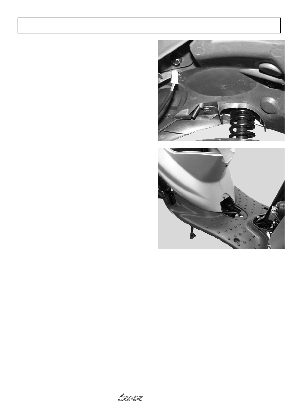
Front part 2:
Connect the steering lock
Fit the ACI 100 module to the legshield front panel, 2
screws (100cc)
Feed the front brake caliper through the legshield
Attach the legshield front panel with the 2 upper
screws
Feed the transponder antenna through the legshield
front panel without clipping it to the lock (100 cc)
Clip the legshield front panel to the main fairings
Fix the front panel to the lower crossmember, 2
screws, and to the main fairings, 1 centre screw
Grease the lower race and fit the 21 ball bearings
Grease the upper race
Engage the complete fork into the fork tube
Fit the ball cage in the upper race
Fit the stack of steering nuts and washers
, Check that the steering play is correct
Fit the handlebar assembly and fit and tighten the
handlebar fixing bolt
Clip the antenna to the steering lock (100cc)
Fit the front brake caliper to the fork tube (2 screws
and 2 washers)
Connect the speed sensor to the main harness
Fix the sensor to the upper crossmember with a clip
Fit the footboard with the battery box
Position the starter motor relay and the battery harness
in the footboard
Fit the rear cover assembly but do not tighten it
Connect the rear light
Fit and connect the battery
, Test all of the machine electrical functions
Reproduction or translation, even partial, are forbidden without the written consent of Peugeot Motocycles
Page: 45
Page 46
FRAME
End of reassembly:
Fit the rear mudflap (4 screws) 2 side screws and 2
screws which also secure the mudguard
Connect the number plate light (100cm3)
Secure the footboard to the frame (4 screws)
Fit the rear cover screws (2 side screws, 1 screw and
one plastic rivet above the battery cover)
Fit the grab handle (2 nuts and 1 screw with washer)
Fit the battery cover (1 screw)
Fit the legshield rear panel (8 screws) and speedo
upper cover (4 screws)
Refit the saddle/storage compartment assembly
Carry out a road test to check the whole of the machine
Reproduction or translation, even partial, are forbidden without the written consent of Peugeot Motocycles
Page: 46
Page 47
Reproduction or translation, even partial, are forbidden without the written consent of Peugeot Motocycles
Page 48

RECOMMENDED
C/PS/
ISO 9001
QUALITY SYSTEM S
CERTIFICATION
CERTIFICATE N° SQ/766
REF: 11.754721.00
Ever aiming at improvement, Peugeot Motocycles reserves the right to delete, modify or add all part numbers listed in
D
Reproduction or translation, even partial, are forbidden without the written consent of Peugeot Motocycles
ATR printed in EU 12/2000
 Loading...