

Sales division
Technical network leadership
WORKSHOP MANUAL
-


TABLE OF CONTENTS
1
Reproduction or translation, even partial, is forbidden without the written consent of Peugeot Motocycles
TABLE OF CONTENTS
TABLE OF CONTENTS..................................................................................................................................... 1
PRODUCTS DANGER SYMBOLS USED......................................................................................................... 4
CHARACTERISTICS.........................................................................................................................................6
Engine........................................................................................................................................................6
Capacities..................................................................................................................................................6
Chassis......................................................................................................................................................6
Dimensions and weight..............................................................................................................................7
Tyres ..........................................................................................................................................................7
Brakes........................................................................................................................................................8
SERVICE SCHEDULE AND COMMISSIONING...............................................................................................9
To be checked at each service...................................................................................................................9
Service operations ...................................................................................................................................10
Time required for maintenance................................................................................................................10
Battery preparation (Except battery without maintenance)* ....................................................................11
New machine preparation........................................................................................................................11
SPECIAL IMPORTANT POINTS.....................................................................................................................12
Oil and fuel...............................................................................................................................................12
TIGHTENING TORQUES ................................................................................................................................ 13
Engine part ..............................................................................................................................................13
Body panels.............................................................................................................................................13
Cycle part.................................................................................................................................................14
Standard ..................................................................................................................................................14
SPECIAL TOOLS............................................................................................................................................ 15
STANDARD TOOLS........................................................................................................................................16
LOCATION OF COMPONENTS......................................................................................................................17
TABLE OF CONTENTS
2
Reproduction or translation, even partial, is forbidden without the written consent of Peugeot Motocycles
BODY PANELS............................................................................................................................................... 18
Location of body components..................................................................................................................18
Body component sequence of disassembly.............................................................................................19
Removal of the rear storage compartment ..............................................................................................20
Removal of the rear cover assembly and mudflap...................................................................................20
Removal of the RH or LH central cover panel..........................................................................................21
Removal of the instrument cluster ...........................................................................................................22
Removal of the RH or LH under body panel............................................................................................22
Removal of the front top shield panel.......................................................................................................23
Removal of the rear shield panel .............................................................................................................23
Removal of the front lower shield pannel.................................................................................................24
Removal of the footboard.........................................................................................................................25
SERVICE OPERATIONS.................................................................................................................................26
Changing the engine oil ...........................................................................................................................26
Draining the relay box..............................................................................................................................27
Removal of the spark plug .......................................................................................................................28
Replacing the air filter ..............................................................................................................................28
Transmission............................................................................................................................................29
Installing the valve clearance...................................................................................................................34
Idle setting................................................................................................................................................35
Removal of the fuel filter ..........................................................................................................................36
Brake inspection ......................................................................................................................................36
Replacing the brake pads ........................................................................................................................36
Checking the brake fluid level..................................................................................................................37
Rear brake linings....................................................................................................................................38
Draining the front fork ..............................................................................................................................41
MISCELLANEOUS OPERATIONS ................................................................................................................. 44
Removal of the fork..................................................................................................................................44
Replacing the bearings of the steering system........................................................................................44
Steering system tightening method..........................................................................................................46
Changing the front fork seals...................................................................................................................48
The fork and its components....................................................................................................................48
TABLE OF CONTENTS
3
Reproduction or translation, even partial, is forbidden without the written consent of Peugeot Motocycles
ELECTRICITY..................................................................................................................................................53
Ignition principle schematic......................................................................................................................53
Regulator/Ignition unit..............................................................................................................................54
Checking the ignition system ...................................................................................................................54
Removal of the fuel gauge.......................................................................................................................55
Removal of the high tension coil..............................................................................................................55
FUEL SYSTEM................................................................................................................................................ 56
Removal of the fuel tank ..........................................................................................................................56
Removal of the carburettor.......................................................................................................................56
The carburettor and its components ........................................................................................................62
POWER UNIT.................................................................................................................................................. 63
Removal of the power unit .......................................................................................................................63
Removal of the cylinder head...................................................................................................................64
Removal of the camshaft and/or rockers .................................................................................................66
Removal of the valves or valve stem seals..............................................................................................67
Fitting the cylinder head...........................................................................................................................68
Method for tightening the cylinder head...................................................................................................68
Setting the timing.....................................................................................................................................69
Checking the timing .................................................................................................................................70
PRODUCTS DANGER SYMBOLS USED
4
Reproduction or translation, even partial, is forbidden without the written consent of Peugeot Motocycles
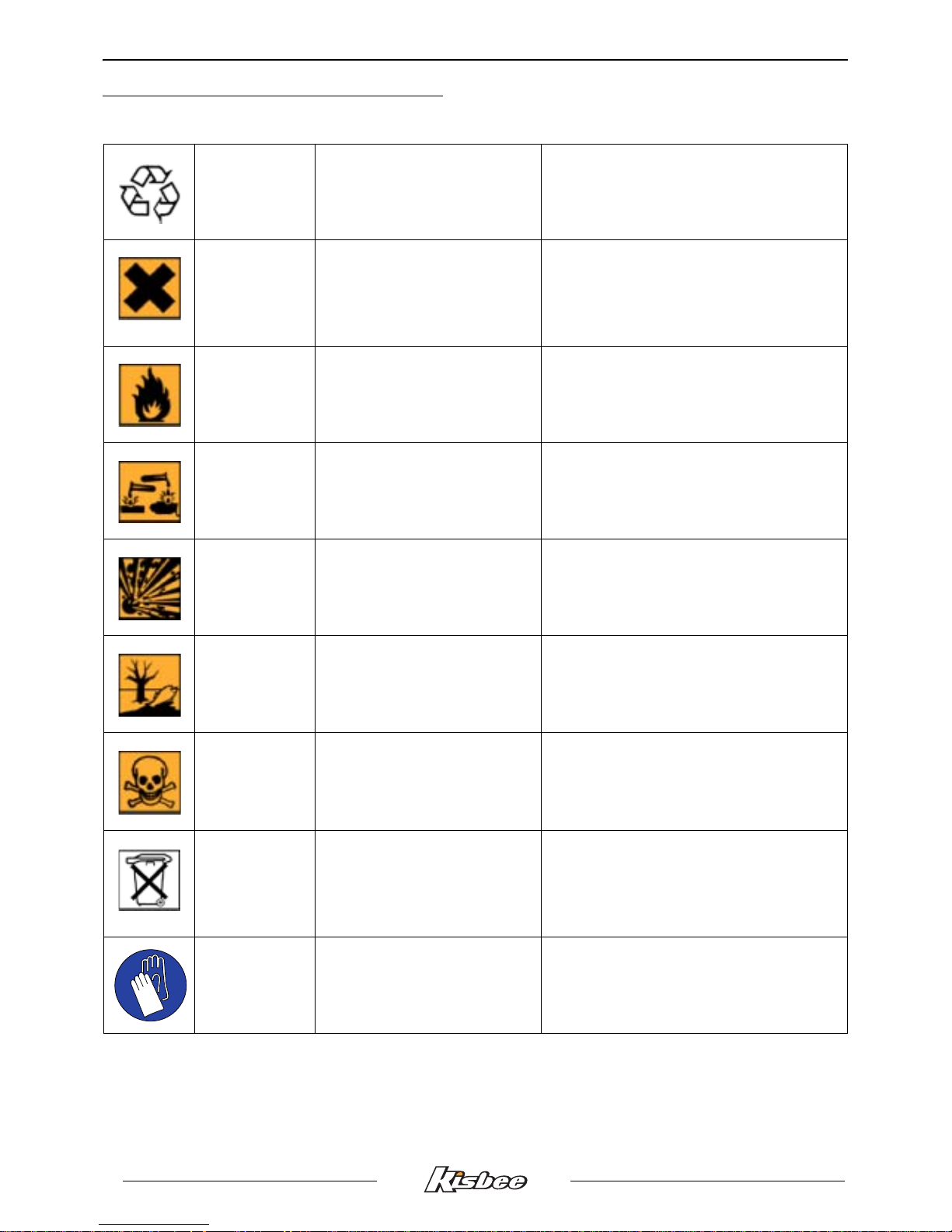
PRODUCTS DANGER SYMBOLS USED
Protection of individuals and of the environment.
Möbius band Recyclable.
Means that the product or the package
can be recycled. However, this does not
guarantee that the product will be
recycled.
Irritant
The product can irritate the
skin, eyes and respiratory
organs.
Avoid contact with skin and clothes. Wear
gloves, safety glasses and appropriate
clothing such as a cotton overall. Do not
breath fumes. If in contact, wash
thoroughly with water.
Flammable The product is flammable.
Keep it away from any flame or heat
source (barbecue, radiator, heating, etc.).
Do not leave the product in the sun.
Corrosive
The product can damage living
tissues or other surfaces.
Avoid contact with skin and clothes. Wear
gloves, safety glasses and appropriate
clothing such as a cotton overall. Do not
breath fumes.
Explosive
The product can explode under
certain circumstances (flame,
heat, impact, friction).
Avoid impacts, friction, sparks and heat.
Hazardous to the
environment
The product affects fauna and
flora. Do not dump it in
dustbins, sinks or in the
environment.
The ideal solution is to bring this product
to your nearest household waste recycling
centre.
Toxic
The product can seriously
affect health if it is inhaled,
ingested or in contact with skin.
Avoid direct contact with the body, even by
inhalation. If you feel unwell, seek medical
advice immediately.
Do not throw
away into a
garbage can
One of the product's
component is toxic and can be
hazardous to environment.
i.e.:. Used batteries.
This symbol informs the consumer that the
used product shall not be thrown away into
a garbage can, but shall be brought back
to the merchant or dropped at a specific
collection point.
Compulsory
gloves
Operation that can be
dangerous for people.
People's safety can be seriously affected if
the recommendations are not fully
respected.

PRODUCTS DANGER SYMBOLS USED
5
Reproduction or translation, even partial, is forbidden without the written consent of Peugeot Motocycles
People's safety
Operation that can be
dangerous for people.
People's safety can be seriously affected if
the recommendations are not fully
respected.
Important
Operation that can be
hazardous to the vehicle.
Indicate the specific procedures that shall
be followed in order not to damage the
vehicle.
Good operating
condition of the
vehicle
The operation must be carried
out in strict compliance with the
documents.
Serious damage to the vehicle and in
certain cases a cancellation of the
warranty can be involved if the
recommendations are not fully respected.
Note Operation that can be difficult.
Indicate a note which gives key
information to make the procedure easier.
Lubricate
Lubricate the parts to be
assembled.
Indicate the specific procedures that shall
be followed in order not to damage the
vehicle.
Grease
Grease the parts to be
assembled.
Indicate the specific procedures that shall
be followed in order not to damage the
vehicle.
Glue
Glue the parts to be
assembled.
Indicate the specific procedures that shall
be followed in order not to damage the
vehicle.
New part Use a new part.
Indicate the specific procedures that shall
be followed in order not to damage the
vehicle.
GLUE
CHARACTERISTICS
6
Reproduction or translation, even partial, is forbidden without the written consent of Peugeot Motocycles
CHARACTERISTICS
Engine
Capacities
Chassis
Marking 139 QMB-E
Type
4-stroke single-cylinder
2 valves per cylinder with chain driven overhead camshaft
Cooling
By a circulation of forced air by means of a turbine on the flywheel
magneto
Bore x stroke 39 x 41.4 mm
Cubic capacity 49 cc
Max. power output 2.7 kW at 7200 rpm
Max. torque rating 3.6 Nm at 7000 rpm
Compression 8.95 bars 500 rpm
Lubrication
Pressurised wet sump lubrication.
Trochoid pump driven by a chain from the crankshaft
Transmission By 2 variable pulleys and V-type belt
Clutch Centrifugal automatic
Exhaust Catalytic
Starter motor By kick starter or electric starter
Spark plug
NGK CR7HSA
Electrode gap: 0.6 to 0.7 mm
Magneto flywheel 90 W
Fuel supply Carburettor. Deni DPD 18J
Standards Euro 2
Crankcase
0.8 l SAE 5W40
Minimum grade: API SL/SJ
Relay box
0.12 l SAE 80W90
Minimum grade: API GL4
Fuel tank 6.8 l 95 or 98 lead-free
Fork 0.035 l per tube (Hydraulic oil SAE 10W)
Chassis Steel tube
Front suspension
Hydraulic telescopic fork. Ø27 mm
Travel: 68 mm
Rear suspension
Combined spring and hydraulically-damped shock absorber
Travel: 68 mm
CHARACTERISTICS
7
Reproduction or translation, even partial, is forbidden without the written consent of Peugeot Motocycles
Dimensions and weight
Tyres
Overall length
1849 mm
Width at handlebar
667 mm
Height (without rear-view
mirrors)
1156 mm
Wheelbase 1256 mm
Saddle height
760 mm
Unladen weight
95 kg
Front wheel rim 12 inch aluminium alloy
Front tyre 110/70 - 12
Front tyre pressure 1.6 bars
Rear wheel rim 12 inch aluminium alloy
Rear tyre 110/70 - 12
Rear tyre pressure 1.8 bars

CHARACTERISTICS
8
Reproduction or translation, even partial, is forbidden without the written consent of Peugeot Motocycles
Brakes
Front brake Single disc type, hydraulic control
Disc diameter and
thickness
170 mm - 4 mm
Front caliper Floating caliper equipped with one piston
Rear brake cable-controlled, single cam drum type
Brake drum diameter 110 mm
Brake lining thickness 4 mm
Chassis markings Engine marking
Manufacturer's plate (1) Engine number (2)
Chassis no. (3)
1
XXXXXX-X
*
XXXXXXXX
*
2
xxxxxxxxxxxxxxxxx
3
SERVICE SCHEDULE AND COMMISSIONING
9
Reproduction or translation, even partial, is forbidden without the written consent of Peugeot Motocycles
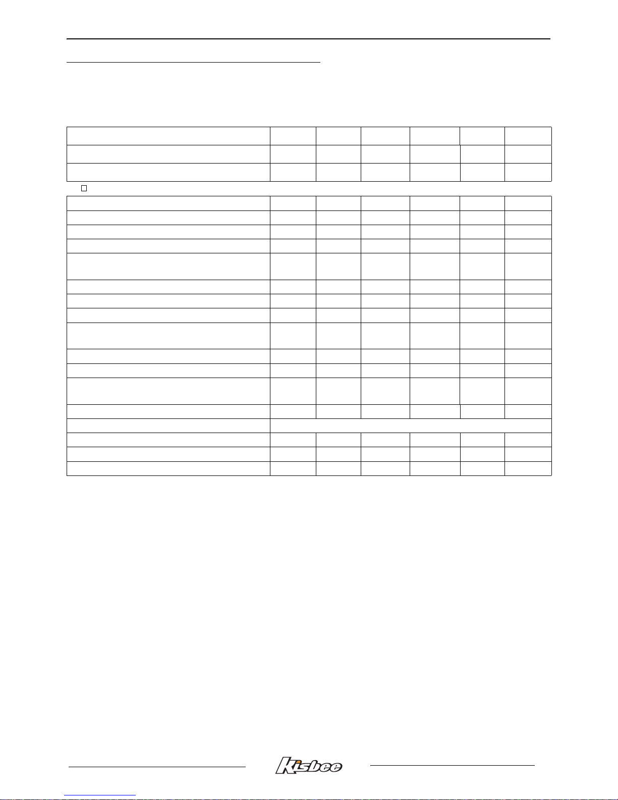
SERVICE SCHEDULE AND COMMISSIONING
Heavy duty servicing applies to vehicles used under rugged operating conditions: door-to-door
deliveries, intensive urban use (courier), short journeys with engine cold, dusty areas, ambient
temperature over 30°C.
Service operations 500 2000 5000 10000 15000 20000
Heavy duty servicing 500 1000 2500 5000 7500 10000
Minimum servicing
1 month 6 months 12 months 24 months 36 months 48 months
To be checked at each service
Steering column play V V V V V V
Wheel bearing play C C C C C C
Throttle cable play V V V V V V
Operation of electrical equipment V V V V
Condition of the front brake hydraulic
control
V V V V V V
Brake fluid level V V V V V V
Front brake pad wear C C C C C C
Rear brake lining wear C C C C C C
Joints. (Central stand. Brake levers. Rear
brake cam...)
G G G G
Condition of petrol pipes C C C C C C
Tyre condition, pressure and wear C C C C C C
State of front suspension. State of rear
suspension
V V V V V V
Battery electrolyte level. Battery charge. V V V V V V
Engine oil level Every 1000 kms
Headlight height adjustment V V V V V V
Tightness of nuts and bolts V V V V V V
Overall operation. Road test V V V V V V
V: Check, clean, adjust. N: Clean.
R: Change. C: Inspect and change if necessary.
G: Check, clean, lubricate.
SERVICE SCHEDULE AND COMMISSIONING
10
Reproduction or translation, even partial, is forbidden without the written consent of Peugeot Motocycles
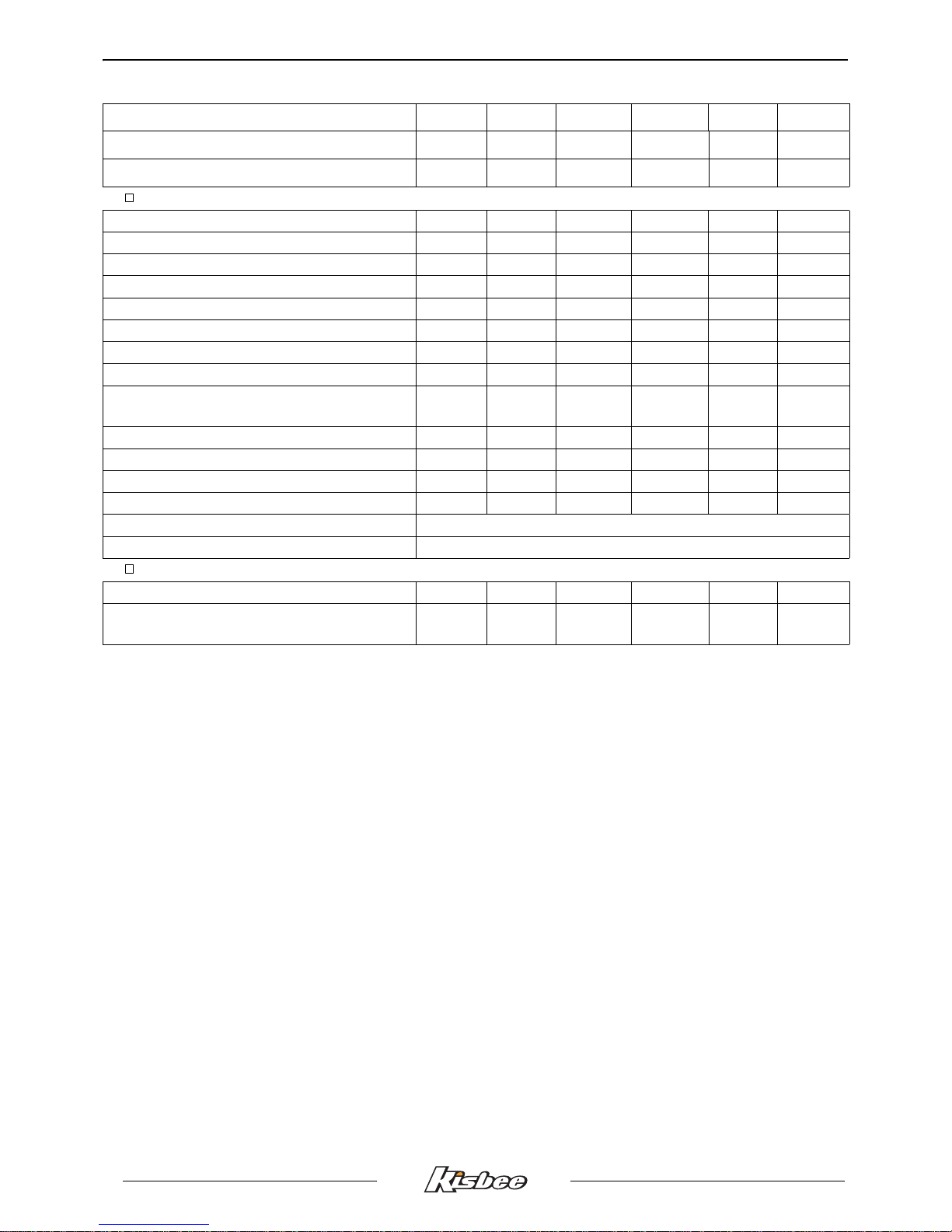
Service operations 500 2000 5000 10000 15000 20000
Heavy duty servicing 500 1000 2500 5000 7500 10000
Minimum servicing
1 month 6 months 12 months 24 months 36 months 48 months
Service operations
Spark plug V R R R R
Air filter R R
Intake silencer drain N N
Drive pulley bearings and guides V C V C
Transmission belt R R
Kick starter mechanism G G
Valve clearances V V V V V
Setting the carburettor V V
Joints. (Central stand. Brake levers. Rear
brake cam)
G G G G
Petrol filter R
Engine oil (+ clean strainer) R R R R R R
Relay box oil R R R R R
Fork oil R
Petrol pipe Once every 5 years
Brake fluid Once every 2 years
Time required for maintenance
Code 9100 9150 9300 9400 9500 9600
Servicing time in tenths of an hour
(0.5 h = 30 min)
1.2 1.8 2.6 3.3 2.6 4.6
V: Check, clean, adjust. N: Clean.
R: Change. C: Inspect and change if necessary.
G: Check, clean, lubricate.
SERVICE SCHEDULE AND COMMISSIONING
11
Reproduction or translation, even partial, is forbidden without the written consent of Peugeot Motocycles
Battery preparation (Except battery without maintenance)*
Remove the battery.
Remove the 6 filler caps and the vent plug.
Fill all the battery cells with electrolyte to the upper level shown on the battery " UPPER LEVEL".
Electrolyte: (35% sulfuric acid = 1.28g/cm3). 0.5 litre can P/N 739733.
Leave the battery to stand for around half an hour.
Top up if necessary.
Charge the battery for at least 2 hours with a current of 0.4 A.
Refit the battery and connect the vapour vent pipe.
Connect the red wire lug to the battery's + terminal, and the green wire lug to the battery's - terminal.
Then, the battery level should be topped up if necessary, after fully charging, using distilled water only.
* Depending on equipment.
New machine preparation
Check the tightness of the carburettor float chamber drain screw.
Check the wheel nuts are tight.
Check nuts and bolts are tight.
Check brake adjustment and efficiency.
Check the tyre pressures cold.
Check operation of the lights, flashers, horn, and brake light.
Check the different warning lights work.
Carry out a road test.
SPECIAL IMPORTANT POINTS
12
Reproduction or translation, even partial, is forbidden without the written consent of Peugeot Motocycles
SPECIAL IMPORTANT POINTS
Oil and fuel
This engine is designed to run on 95 or 98 unleaded fuel only.
Fuel pipes must absolutely be changed if there are any signs of wear, cracks, etc.
The air pipe between the air pump and the exhaust is specific owing to its heat resistance
properties.
Should it be changed, replace it with a genuine pipe.
Petrol is highly inflammable, do not smoke in the working area and avoid proximity to flames or
sparks.
Before carrying out any work, leave the engine to cool for at least 2 hours.
TIGHTENING TORQUES
13
Reproduction or translation, even partial, is forbidden without the written consent of Peugeot Motocycles
TIGHTENING TORQUES
Engine part
Body panels
Spark plug 18 Nm
Filler cap 20 Nm
Screen 30 Nm
Relay box drain plug 12 Nm
Relay box filler cap 12 Nm
Cylinder head cover 10 Nm
Cylinder head
• 7 mm diameter nut
• 6 mm diameter screw
18 Nm
8 Nm
Crankcase 10 Nm
RH casing cover 10 Nm
Automatic tensioner 10 Nm
Automatic tensioner plug 8 Nm
Starter motor 10 Nm
Rotor 50 Nm
Stator 8 Nm
Engine speed sensor 6 Nm
Transmission cover 10 Nm
Turbine 10 Nm
Drive pulley 50 Nm
Driven pulley 50 Nm
Clutch plate and shoes 50 Nm
Inlet manifold 10 Nm
Front mudguard 8 to 10 Nm
Handlebar cover 2 to 4 Nm
Front shield panel 2 to 4 Nm
Rear shield 2 to 4 Nm
Bottom panel 2 to 4 Nm
Floor panel 6 to 8 Nm
Saddle storage compartment 8 to 10 Nm
Rear body panels 6 to 8 Nm
Grab handle 20 to 25 Nm
Rear mudguard 2 to 4 Nm
TIGHTENING TORQUES
14
Reproduction or translation, even partial, is forbidden without the written consent of Peugeot Motocycles
Cycle part
Standard
Front wheel spindle 60-70 Nm
Rear wheel spindle nut 110-130 Nm
Linkrod to engine pivot 57±5 Nm
Linkrod to frame pivot 57±5 Nm
Shock absorber top mount 43-50 Nm
Shock absorber bottom mount 20-25 Nm
Exhaust to cylinder head mounting nut 15-18 Nm
Exhaust to casing mounting bolt 20-25 Nm
Upper cone (in 2 operations) 38-42 Nm
15-19 Nm
Upper cone locknut Hand tightened
Steering locknut 70-80 Nm
Handle bar 35-45 Nm
Front brake caliper 27-32 Nm
Front brake disc 27-32 Nm
Fastening screw for brake linkrod on cam 8-11 Nm
Fastening screw for fork stanchion on tee 30-40 Nm
Nut and bolt 5 mm diameter 5 Nm
Nut and bolt 6 mm diameter 10 Nm
Nut and bolt 8 mm diameter 22 Nm
Nut and bolt 10 mm diameter 35 Nm
Nut and bolt 12 mm diameter 55 Nm
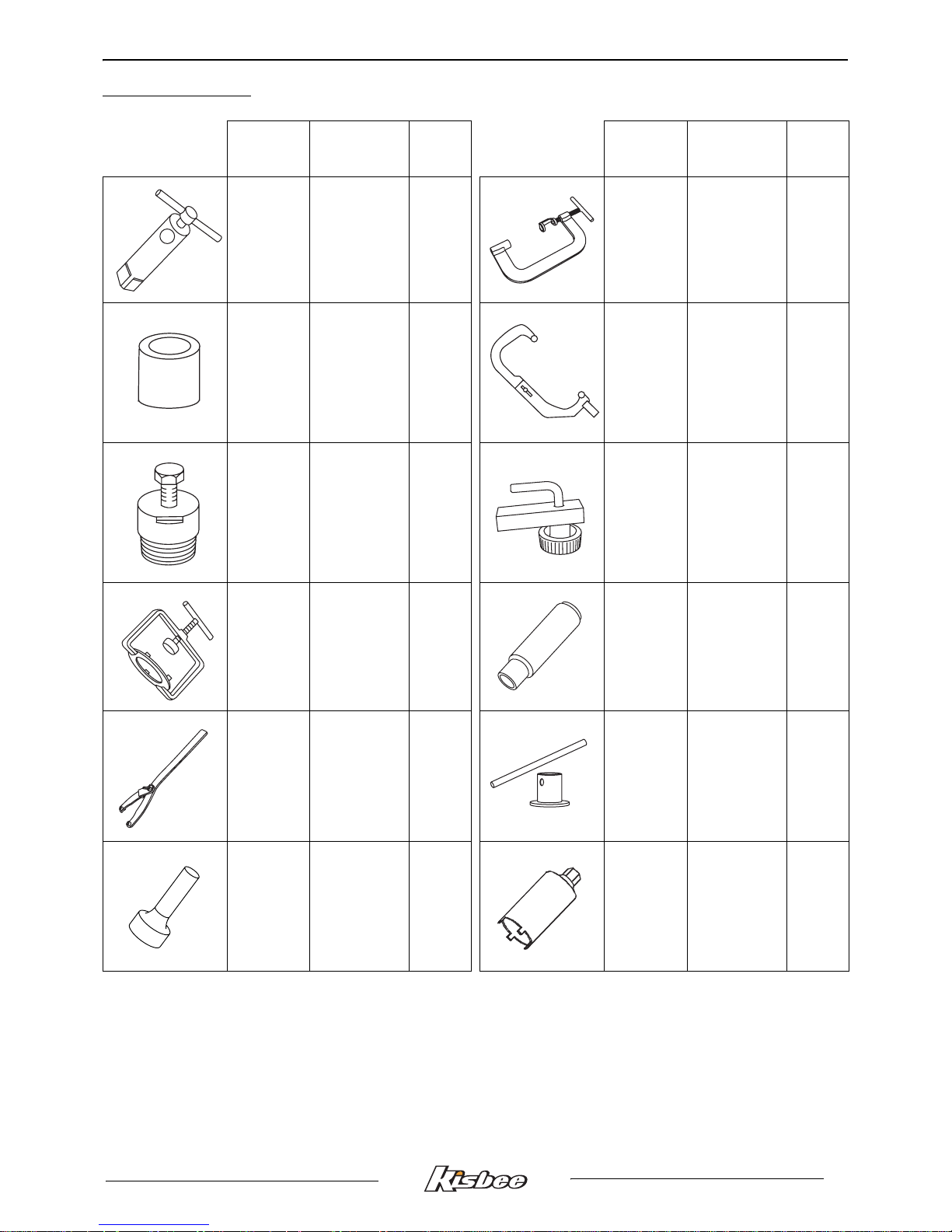
SPECIAL TOOLS
15
Reproduction or translation, even partial, is forbidden without the written consent of Peugeot Motocycles
SPECIAL TOOLS
Tool N° Designation
Used
with
Tool N° Designation
Used
with
64765
Engine mount
755982 754035
Valve lifter
758595
68007
Protective
end-piece
small model
750806 755982
Engine mount
adapter
64765
750806
Flywheel
puller
68007 755996
Hose clamp
752127
Clutch
compression
tool
756725 756668
Lip seal push
tool
752237
Adjustable pin
wrench
756725
38 mm pipe
wrench
752127
753726
Steeing head
cup push tool
757860
Steering tool

STANDARD TOOLS
16
Reproduction or translation, even partial, is forbidden without the written consent of Peugeot Motocycles
Tool N° Designation
Used
with
Tool N° Designation
Used
with
757990
Steeing head
cup push tool
758596
Valve stem
seal drift
758595
Valve spring
lifter adapter
754035 759467
Fixed flange
locking tool
STANDARD TOOLS
Wrenches with interchangeable
end fittings for valve clearance
adjustment
Type: Marolotest P/N 500140
Multimeter
Set of shims
Automatic resetting type torque
wrench
5 to 25 Nm
Type: Facom R.306A25
Automatic resetting type torque
wrench
10 to 50 Nm
Type: Facom J.208A50
Automatic resetting type torque
wrench
40 to 200 Nm
Type: Facom S.208A200
OFF
V
DC
V
AC
Ω
20 m
200 m
DC
10A
V
Ω
COM
mA
Ω
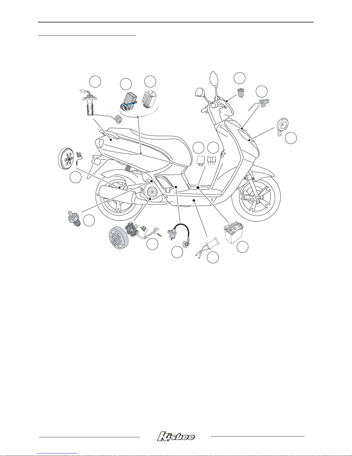
LOCATION OF COMPONENTS
17
Reproduction or translation, even partial, is forbidden without the written consent of Peugeot Motocycles
LOCATION OF COMPONENTS
1. Fuel gauge
2. CDI unit
3. Regulator
4. Starter motor relay
5. Fuse
6. Flasher unit
7. Starter resistor
8. Horn
9. Battery
10.HT coil
11.Ignition sensor
12.Carburetor heater
13.Carburettor heater thermo-switch
14.Drive sensor
NC
-
U
PP
ER
LE
VEL
L
OWE
R
LE
V
E
L
1
4 5
9
7
8
11
2
3
10
6
XX
.X
X
XX
X.
X
XX
X
13
12
14

BODY PANELS
18
Reproduction or translation, even partial, is forbidden without the written consent of Peugeot Motocycles
BODY PANELS
Location of body components
Description.
1. Handlebar front fairing
2. Handlebar rear fairing
3. Legshield top panel
4. Rear shield
5. Front lower legshields
6. Front mudguard
7. Front wheel
8. Mudguard
9. Bottom panel
10.Central bottom panel
11.Floor panel
12.Mudflap
13.Saddle and storage compartment
14.Rear body panels
15.Central panels
NC
5
9
7
8
11
3
6
1
2
4
10
12
14
13
15

BODY PANELS
19
Reproduction or translation, even partial, is forbidden without the written consent of Peugeot Motocycles
Body component sequence of disassembly
1. Handlebar front fairing
2. Handlebar rear fairing
3. Legshield top panel
4. Rear shield
5. Front lower legshields
6. Front mudguard
7. Front wheel
8. Mudguard
9. Bottom panel
10.Central bottom panel
11.Floor panel
12.Mudflap
13.Saddle and storage compartment
14.Grab handle
15.Rear body panels
16.Central panels
* This item may be removed on its own.
9*
14
12*
15
13*
8
7*
2
1*
6*
11
4
5
3*
10
BODY PANELS
20
Reproduction or translation, even partial, is forbidden without the written consent of Peugeot Motocycles
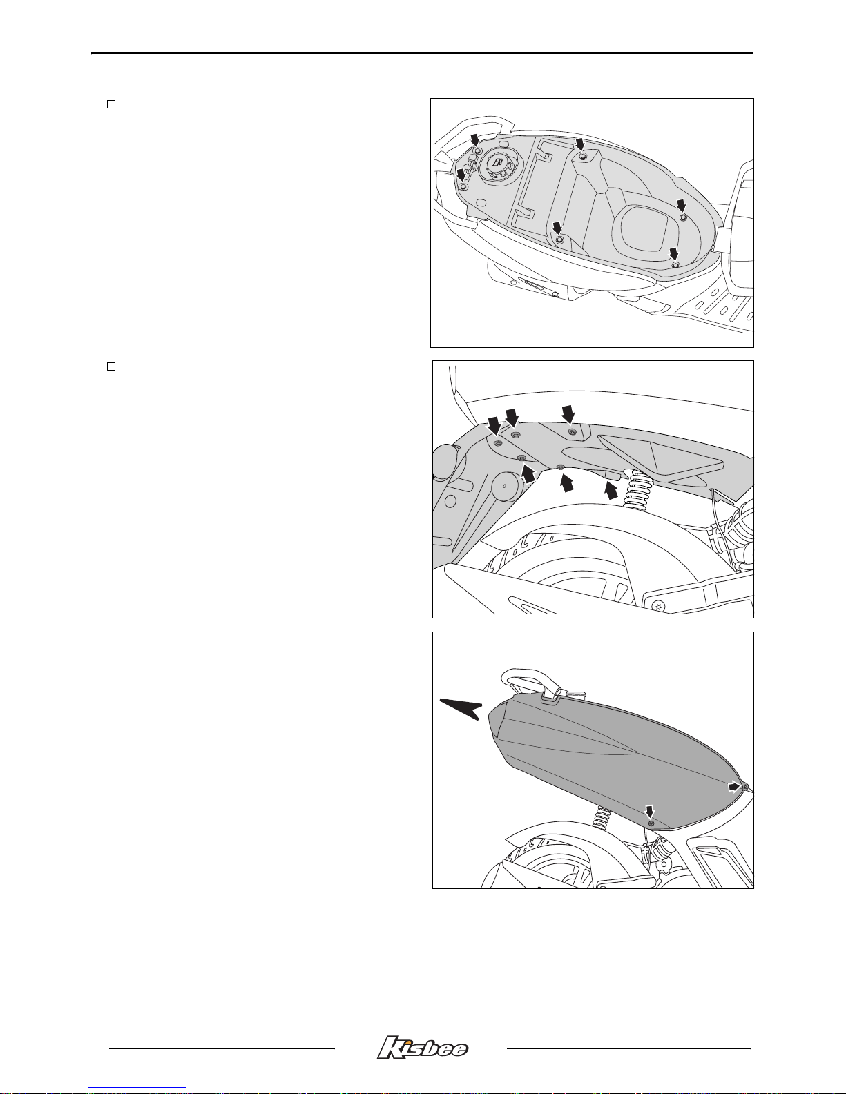
Removal of the rear storage
compartment
Procedure 1.
- Lift the saddle.
- Remove the tank filler cap.
- Remove the storage
compartment (6 screw).
Removal of the rear cover assembly and
mudflap
Procedure 2.
- Remove the rear storage compartment.
See: Procedure 1. page 20.
- Remove the splash guard (6 screw).
- Remove the grab handle (3 screw).
- Remove the rear cover assembly (4 screw).
- Disconnect the taillight.

BODY PANELS
21
Reproduction or translation, even partial, is forbidden without the written consent of Peugeot Motocycles
- Remove the taillight (4 screw).
- Remove the fastening screw on the fairings.
- Separate the 2 fairings.
Removal of the RH or LH central cover
panel
Procedure 3.
- Remove the rear cover assembly. See:
Procedure 2. page 20.
- Remove the battery access door (1 screw).
- Remove the complete footrest
assembly (1 screw).
- Remove the 5 screws from the central
fairing.
 Loading...