

PEUGEOT 50 CC Workshop Manual
Sales division
Technical network leadership
WORKSHOP MANUAL
-
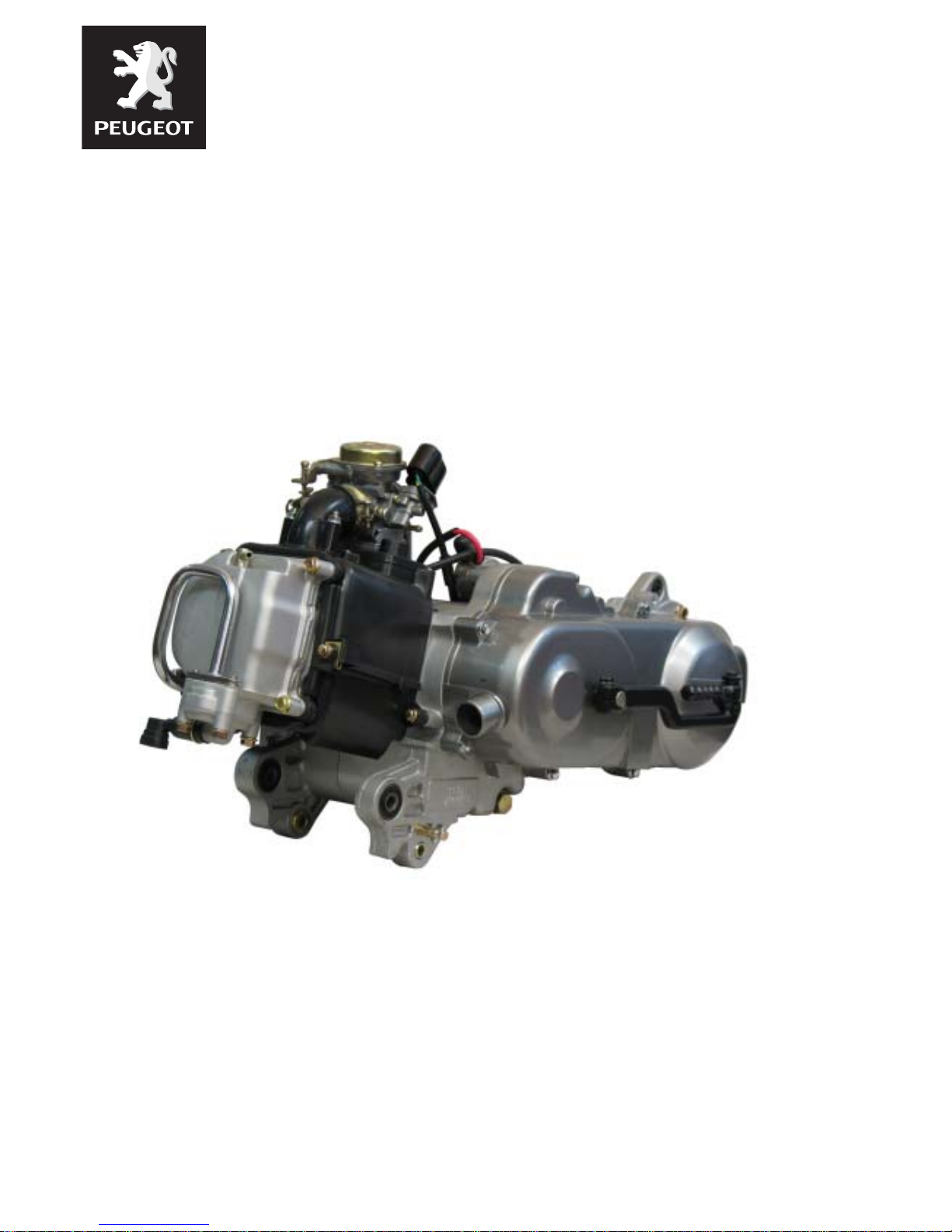
50 CC 4-STROKE ENGINE
2 VALVES
AIR COOLING

Reproduction or translation, even partial, is forbidden without the written consent of Peugeot Motocycles
Workshop manual
Technical network leadership
Reproduction or translation, even partial, is forbidden without the written consent of Peugeot Motocycles

TABLE OF CONTENTS
1
Reproduction or translation, even partial, is forbidden without the written consent of Peugeot Motocycles
TABLE OF CONTENTS
TABLE OF CONTENTS........................................................................................................1
CHARACTERISTICS............................................................................................................3
Capacities............................................................................................................................ 3
SPECIAL IMPORTANT POINTS..........................................................................................4
Oil and fuel .......................................................................................................................... 4
TIGHTENING TORQUE........................................................................................................5
SPECIAL TOOLS.................................................................................................................6
DISASSEMBLY ....................................................................................................................7
Putting the engine on the stand........................................................................................... 7
Removal of the primary transmission cover......................................................................... 7
Removal of the drive pulley.................................................................................................. 8
Removal of the driven pulley................................................................................................ 8
Removal of the intake pipe.................................................................................................. 9
Removal of the cooling volutes............................................................................................ 9
Removal of the rocker cover.............................................................................................. 10
Removal of the pulsair....................................................................................................... 10
Removal of the rotor.......................................................................................................... 11
Removal of the winding and pick-up.................................................................................. 12
Removal of the cylinder head............................................................................................ 13
Removal of the rockers...................................................................................................... 14
Removal of the valves or valve stem seals........................................................................15
Removal of the cylinder..................................................................................................... 16
Removal of the piston........................................................................................................ 17
Removal of the ignition casing........................................................................................... 17
Removal of the oil pump.................................................................................................... 18
Removal of the RH crankcase half.................................................................................... 19
Removal of the crankshaft................................................................................................. 19
Checking the crankshaft and conrod assembly................................................................. 19
Removal of the secondary transmission cover.................................................................. 20
REFITTING SPECIFIC COMPONENTS.............................................................................22
Assembly of the engine casings........................................................................................ 22
Installing the ignition casing. ............................................................................................. 23
Installing the piston rings on the piston. ............................................................................ 24
Fitting the piston................................................................................................................ 24

TABLE OF CONTENTS
2
Reproduction or translation, even partial, is forbidden without the written consent of Peugeot Motocycles
Fitting the cylinder. ............................................................................................................ 25
Fitting the cylinder head. ................................................................................................... 25
Setting the timing............................................................................................................... 26
Installing the valve clearance............................................................................................. 27
Checking the valve clearance............................................................................................ 28
Installing the winding and the pick-up................................................................................ 28
MISCELLANEOUS OPERATIONS ....................................................................................30
Removal of the starter system........................................................................................... 30
Fitting the starter system................................................................................................... 31
Changing the drive pulley bearings................................................................................... 31
Fitting the drive pulley assembly........................................................................................ 32
Removal of the clutch lining assembly............................................................................... 33
Refitting the clutch lining assembly....................................................................................34
Removal of the choke........................................................................................................ 35
Removal of the throttle valve............................................................................................. 35
Removal of the float, needle valve and jets....................................................................... 36
Removal of the engine speed adjuster screw and mixture control screw.......................... 37
CHARACTERISTICS
3
Reproduction or translation, even partial, is forbidden without the written consent of Peugeot Motocycles
CHARACTERISTICS
Capacities
* Not completed
50 cc
Marking *
Type
4-stroke single-cylinder
2 valves per cylinder with chain driven overhead camshaft
Cooling Air
Bore x stroke 39 x 41,4 mm
Cubic capacity 49,58 cc
Max. power output 2 kW at 7000 rpm
Max. torque rating 6000 rpm
Lubrication Trochoidal pump
Transmission By 2 variable pulleys and V-type belt
Clutch Centrifugal automatic
Exhaust Catalytic
Starter motor *
Spark plug NGK CR 7HSA
Magneto flywheel *
Fuel supply Carburetion
Engine oil
0.80 l SAE 5W40
Minimum grade: API SJ
Relay box oil 0.12 SAE 80W90
SPECIAL IMPORTANT POINTS
4
Reproduction or translation, even partial, is forbidden without the written consent of Peugeot Motocycles
SPECIAL IMPORTANT POINTS
Oil and fuel
This engine is designed to run on 95 or 98 unleaded fuel only.
Never run the machine with a petrol/oil mixture.
The fuel pipes must be changed if they show signs of wear, cracks, etc.
Petrol is highly inflammable, do not smoke in the working area and avoid pr oximity to flames or
sparks.
TIGHTENING TORQUE
5
Reproduction or translation, even partial, is forbidden without the written consent of Peugeot Motocycles
TIGHTENING TORQUE
Cylinder head 1.8 m.daN
Cylinder casings 1 m.daN
Transmission cover 1 m.daN
RH casing cover 1 m.daN
Automatic tensioner 0.8/1 m.daN
Starter motor 1 m.daN
Rotor 5m.daN
Stator 0.8 m.daN
Engine speed sensor 0.6 m.daN
Drive pulley 5 m.daN
Driven pulley 5 m.daN
Spark plug 1.8 m.daN
Inlet manifold 1 m.daN
SPECIAL TOOLS
6
Reproduction or translation, even partial, is forbidden without the written consent of Peugeot Motocycles
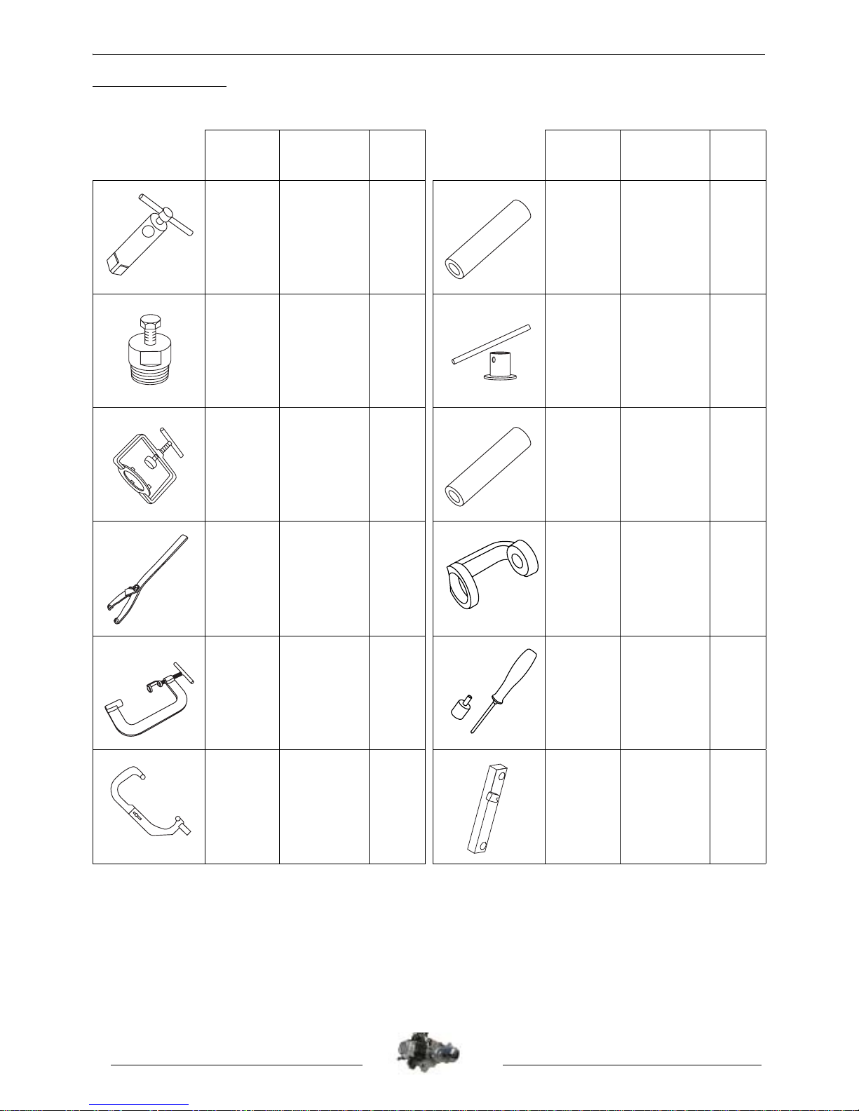
SPECIAL TOOLS
(*) New or modified to ol
Tool N° Designation
Used
with
Tool N° Designation
Used
with
64765
Engine
mount
755982 756668
Lip seal push
tool
750806
Flywheel
puller
756725
8 mm pipe
wrench
752127
752127
Clutch
compression
tool
757990
Lip seal push
tool
752237
Adjustable
pin wrench
758595
Valve spring
lifter adapter
754035
754035 Valve lifter 758595 758596
Valve stem
seal drift
755982
Engine
mount
adapter
64765
759467
(*)
Fixed flange
locking tool
DISASSEMBLY
7
Reproduction or translation, even partial, is forbidden without the written consent of Peugeot Motocycles
DISASSEMBLY
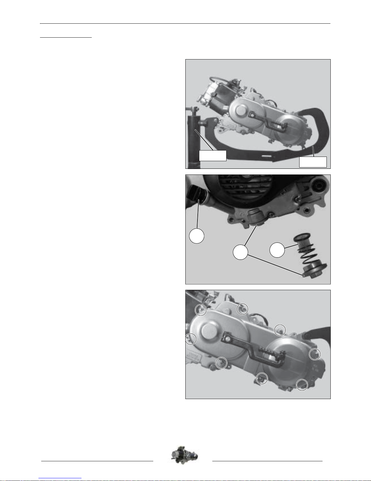
Putting the engine on the stand.
- Fit the engine to adapter P/N 755982.
- Put the assembly on stand P/N 64765
clamped in the jaws of a vice.
- Remove the engine's oil filler cap (1).
- Empty the oil from the engine (2).
Note: Every time oil is changed, the
filter (3) must be cleaned and the Oring changed.
Tightening torque: 4 m.daN.
Removal of the primary transmission
cover.
- Remove the 8 bolts that secure the cover.
- Remove the transmission cover.
- Removal of the gasket.
- Remove the 2 centring pillars.
Tightening torque: 1 m.daN.
Note: Every time it is removed, change the
gasket.
755982
64765
3
2
1
DISASSEMBLY
8
Reproduction or translation, even partial, is forbidden without the written consent of Peugeot Motocycles
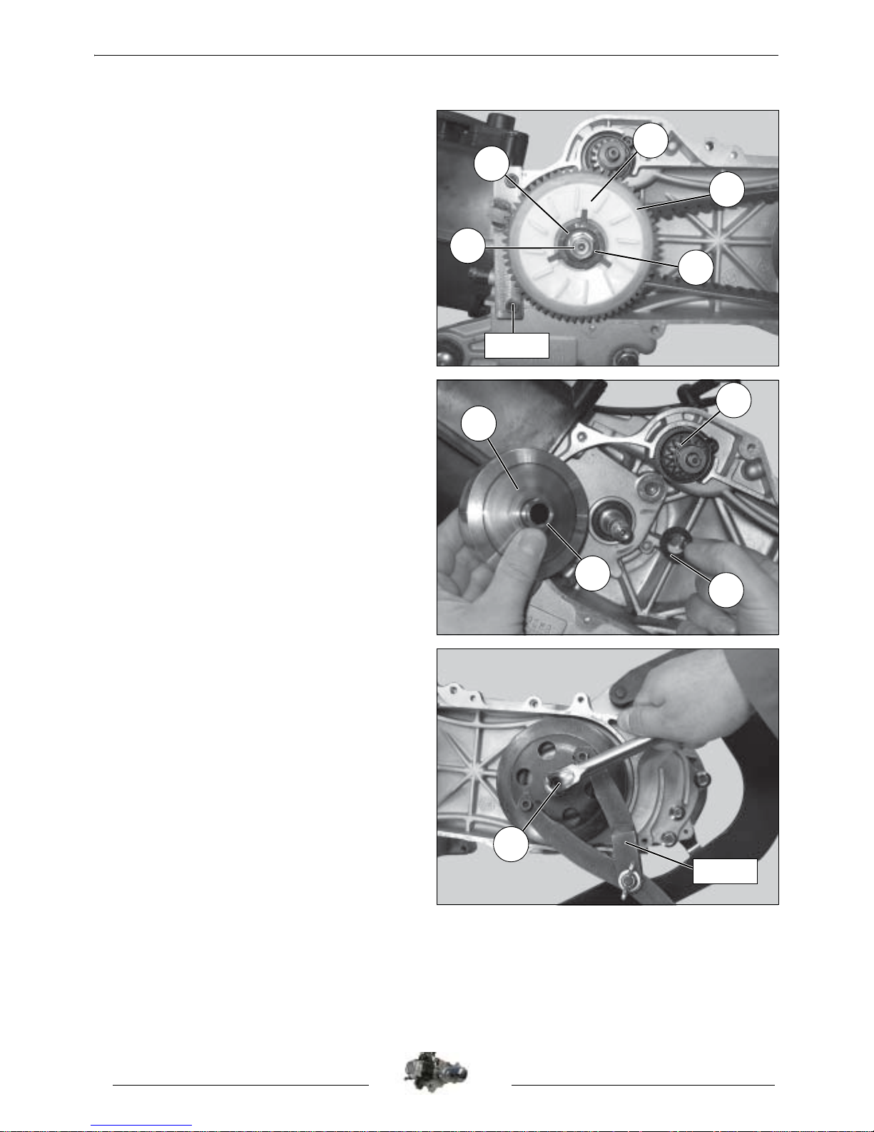
Removal of the drive pulley.
- Hold the fixed flange with tool P/N 759467.
- Remove the nut (1) and washer (2) from the
fixed flange.
- Remove the starter hub (3) and the
turbine (4).
- Remove the fixed flange (5).
Tightening torque: 5 m.daN.
- Remove the belt.
- Remove the drive pulley (6) with the guide
hub (7).
- Remove the washer (8).
- Remove the starter dog (9).
Removal of the driven pulle y.
- Immobilize the clutch drum using the ajustable
pin wrench P/N 752237 or the flywheel clamp
P/N 68570.
- Remove the nut (1).
- Remove the clutch drum and the clutch and
drive pulley assembly.
Tightening torque: 5 m.daN.
759467
2
1
5
4
3
9
7
6
8
1
752237
DISASSEMBLY
9
Reproduction or translation, even partial, is forbidden without the written consent of Peugeot Motocycles
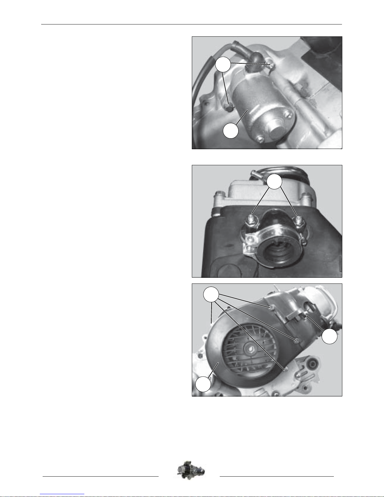
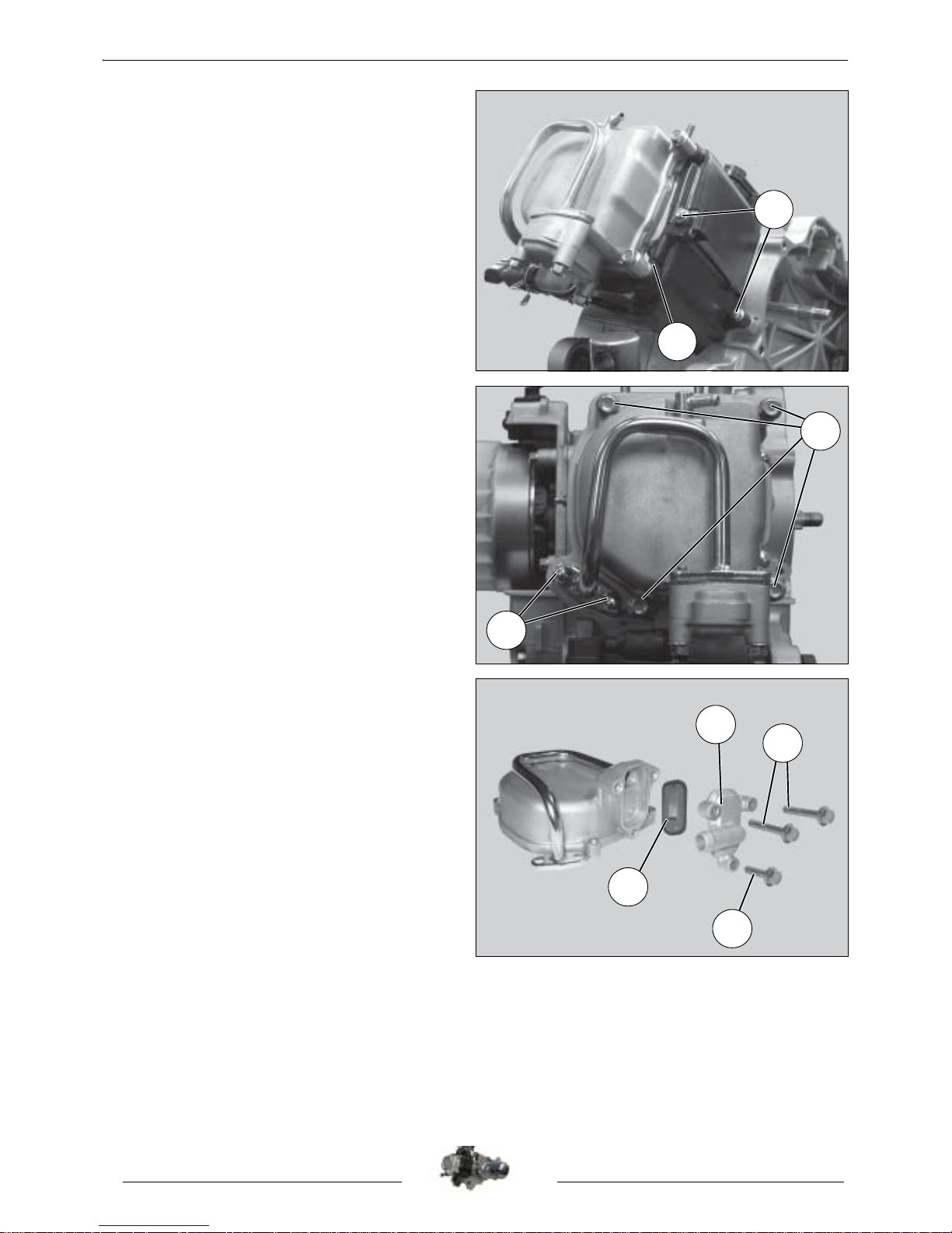
Removal of the starter motor.
- Remove the 2 fixing bolts (1).
- Remove the starter motor (2).
Tightening torque: 1 m.daN.
Note: Check the condition of the starter
motor O-ring.
Removal of the intake pipe.
- Remove the 2 nuts that secure the intake
pipe (1).
- Remove the intake pipe and its plastic spacer.
- ve the 2 O-rings.
Tightening torque: 1 m.daN.
Note: Change the O-rings if necessary.
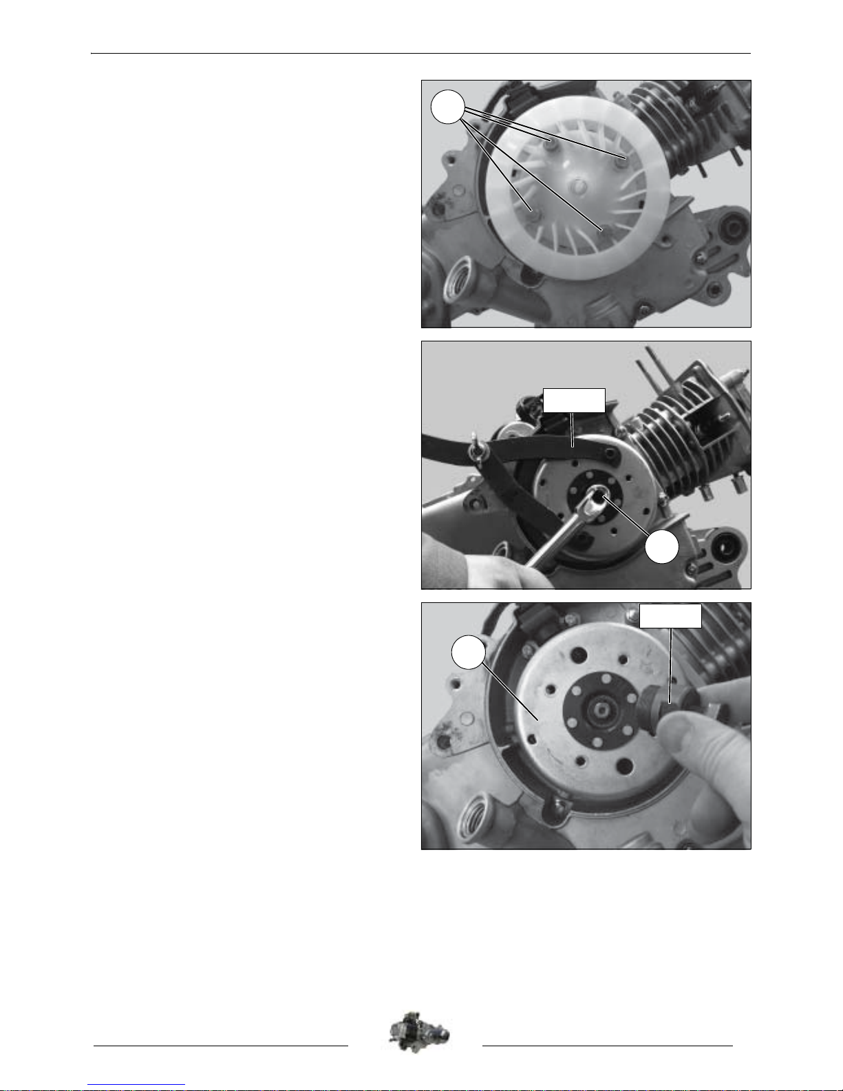
Removal of the cooling volutes.
- Remove the 4 screws (1) that secure the
volute on the flywheel magneto side.
- Remove the volute (2).
- Remove the fastening screw (3).
2
1
1
3
2
1
DISASSEMBLY
10
Reproduction or translation, even partial, is forbidden without the written consent of Peugeot Motocycles
- Remove the 2 screws (4) that secure the
volute on the clutch side.
- Remove the cooling volutes.
- Remove the air seal (5).
Removal of the rocker cover.
- Remove the 4 fixing bolts (1).
- Remove the 2 screws that secure the pulsair
pipe (2).
- Remove the cylinder head cover equipped
with its rubber gasket.
Tightening torque: 1 m.daN.
Note: The O-ring must be changed every
time it is removed.
Removal of the pulsair.
- Remove the pulsair filter.
- Remove the 2 bolts (1).
- Remove the screw (2).
- Remove the pulsair cover (3).
- Remove the flap valve (4).
4
5
1
2
1
2
3
4
DISASSEMBLY
11
Reproduction or translation, even partial, is forbidden without the written consent of Peugeot Motocycles
Removal of the rotor.
- Remove the 4 screws (1) that secure the
turbine.
- Remove the turbine.
Tightening torque: 1 m.daN.
- Lock the rotor with the adjustable pin wrench
P/N 752237.
- Remove the nut (1).
Tightening torque: 5 m.daN.
Important: Using an inappropriate tool can
damage the windings of the flywheel
magneto.
- Tighten flywheel extractor P/N 750806 on the
rotor (2).
- Lock the flywheel extractor and turn the thrust
bolt until the rotor is released.
- Remove the rotor.
1
1
752237
750806
2
DISASSEMBLY
12
Reproduction or translation, even partial, is forbidden without the written consent of Peugeot Motocycles
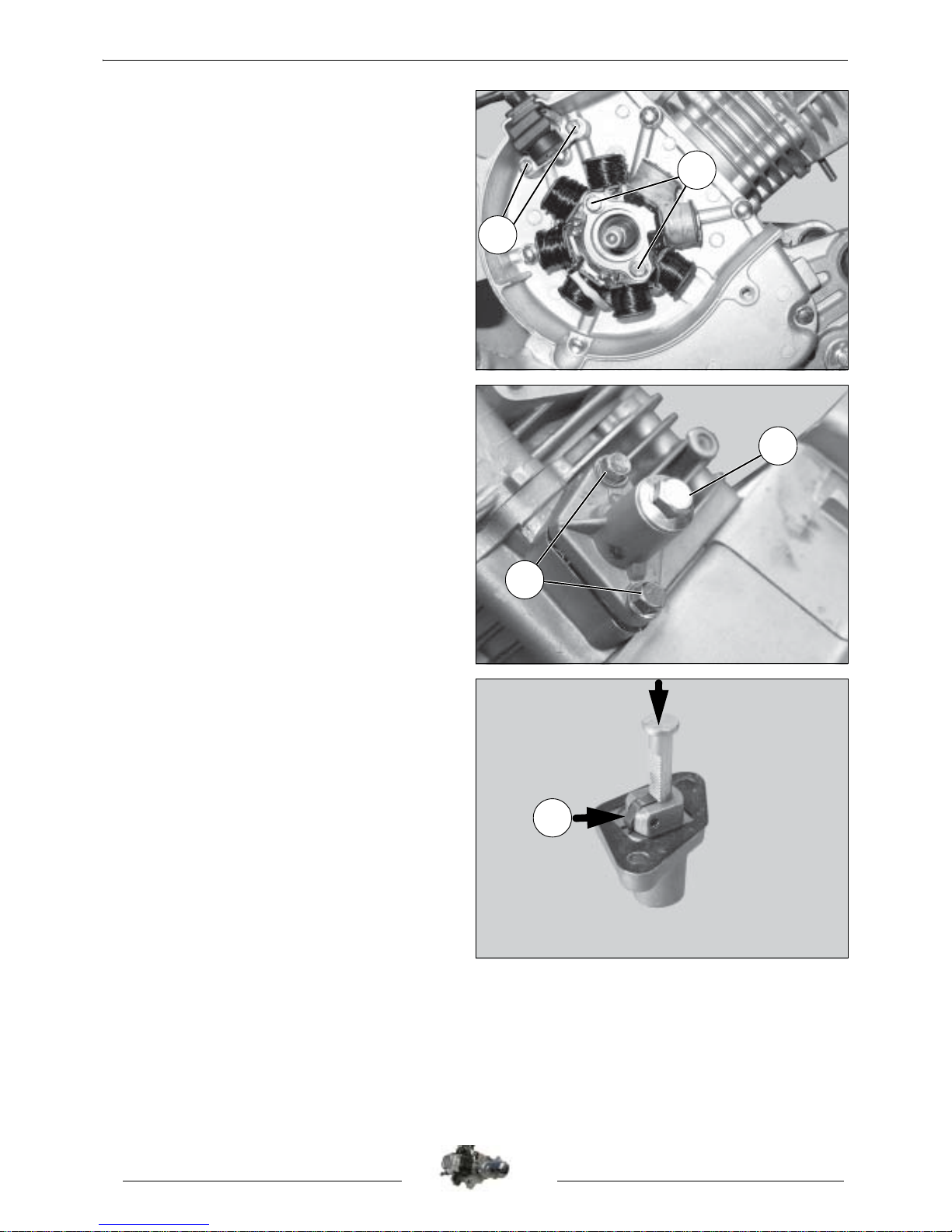
Removal of the winding and pick-up.
- Remove the 2 screws (1) that secure the pickup and the 2 screws (2) that secure the stator
assembly.
- Remove the stator and sensor assembly (3).
Tightening torque:
Screw (1): 0.6 m.daN.
Screw (2): 0.8 m.daN.
Removal of the chain tensioner.
- Remove the screw, the O-ring and the
tensioner spring (1).
- Remove the 2 mounting screws (2) from the
tensioner body.
Tightening torque:
Screw 1: 0.8 m.daN.
Screw 2: 1 m.daN.
- Remove the chain tensioner and slacken it by
pressing the ratchet tooth (A).
- Remove the paper gasket.
1
2
1
2
A
 Loading...