


PetSafe®
In-Ground Fence™
Operating and Training Guide
Please read this entire guide before beginning.
RFA 67-
 BATTERY 6V
Thank you for choosing PetSafe®, the best selling brand of electronic training solutions in the world. Our mission is to be the most trusted brand in the pet ownership experience.We want to ensure your pet’s safety by providing you with the tools and techniques to successfully train your pet. If you have any questions, please contact the Customer Care Center at 1-800-732-2677 or visit our website at www.petsafe.net.
To get the most protection out of your warranty, please register your product within 30 days at www. petsafe.net. By registering and keeping your receipt, you will enjoy the product’s full warranty and should you ever need to call the Customer Care Center, we will be able to help you faster. Most importantly, PetSafe® will never give or sell your valuable information to anyone. Complete warranty information is available online at www.petsafe.net.
___________________________________________
Table of Contents |
|
Components ................................................................................................................................... |
3 |
Other ItemsYou May Need.............................................................................................................. |
3 |
How the System Works .................................................................................................................... |
4 |
Key Definitions ............................................................................................................................... |
4 |
Operating Guide |
|
Locate the Fence Transmitter....................................................................................................... |
5 |
Lay Out the System..................................................................................................................... |
5 |
Sample Layouts........................................................................................................................... |
6 |
Position the Boundary Wire ......................................................................................................... |
7 |
Connect the Wires to the Fence Transmitter ................................................................................. |
8 |
Prepare the Receiver Collar.......................................................................................................... |
8 |
Set the Boundary Width and Test the Receiver Collar.................................................................... |
9 |
Install the Boundary Wire ........................................................................................................... |
10 |
Place the Boundary Flags ........................................................................................................... |
11 |
Fit the Receiver Collar................................................................................................................ |
11 |
Training Guide |
|
Be Patient WithYour Pet ............................................................................................................. |
13 |
Days 1 and 2 - Boundary Flag Awareness .................................................................................... |
13 |
Days 3 and 4 - Continue Boundary Flag Awareness..................................................................... |
14 |
Days 5 thru 8 - Distraction Phase ............................................................................................... |
14 |
Days 9 thru 14 - Unleashed Supervision...................................................................................... |
14 |
Days 15 thru 30 - Pet Monitoring ............................................................................................... |
15 |
TakingYour Pet Out of the Pet Area ............................................................................................ |
15 |
Accessories .................................................................................................................................... |
15 |
Troubleshooting............................................................................................................................. |
16 |
Short Loop Test ............................................................................................................................. |
17 |
To Locate a Break in the Wire ......................................................................................................... |
17 |
Terms of Use and Limitation of Liability ......................................................................................... |
18 |
Compliance ................................................................................................................................... |
18 |
Customer Care International .......................................................................................................... |
18 |
Caution ......................................................................................................................................... |
19 |
Layout Grid ................................................................................................................................... |
20 |
Mounting Template ........................................................................................................................ |
20 |
2 |
1-800-732-2677 |
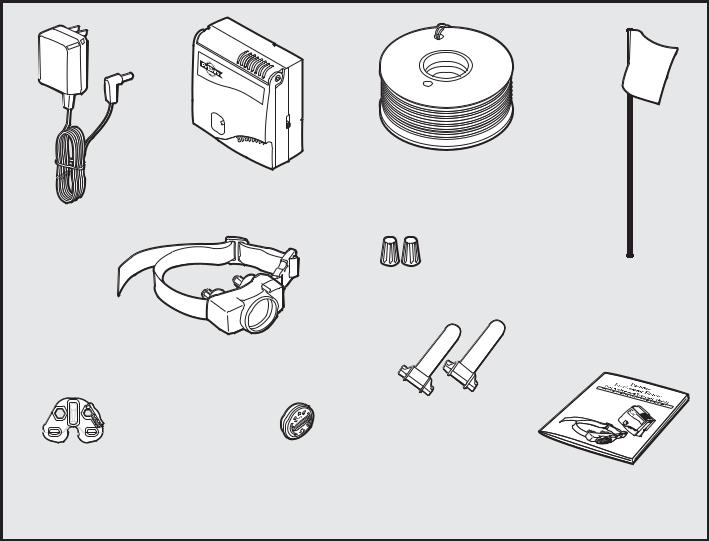
Components
Fence |
Boundary Wire - 500 ft. |
Transmitter |
|
Power
Adapter
Boundary Flags - 50
Wire Nuts
Receiver
Collar
Gel-filled
Capsules
Test Light |
Battery |
Tool |
(PetSafe® RFA-67) |
Operating and
Training Guide
Other Items You May Need
•Additional wire and flags (Part #PRFA-500)
•Tape measure
•Small Phillips screwdriver
•Drill & mounting hardware
•Shovel or lawn edger
•Pliers
•Wire stripping pliers
•Scissors
•Lighter
•Electrical tape
•Gel-filled Capsules
•Additional wire nuts
•Waterproofing compound (e.g. silicone caulk)
•PVC pipe or water hose
•Circular saw with masonry blade
•Staple gun
•Non-metallic collar and leash
Fence installation and training help, interactive fence planning software: www.petsafe.net/fence
www.petsafe.net |
3 |

How the System Works
A radio signal travels from the Fence Transmitter through a buried wire, marking the boundaries you wish to set for your dog.Your dog wears a Receiver Collar that detects the signal at the boundary. As your dog approaches the boundary, the receiver issues a warning tone. If he proceeds further, he receives a safe but startling Static Correction.While harmless, the correction will persuade him to stay in the containment area you’ve established. Boundary flags are a temporary visual aid for your pet; remove them after training.This PetSafe® In-Ground Fence™ has been proven safe, comfortable, and effective for pets over 8 pounds.
Key Definitions
Fence Transmitter: Transmits the radio signal through the Boundary Wire.
Pet Area: Area within the Warning Zone where your pet can roam freely.
Warning Zone: Outer edge of the Pet Area where your pet’s Receiver Collar begins to beep, warning him not to go into the Static Correction Zone.
Static Correction Zone: Zone beyond the Warning Zone where your pet’s Receiver Collar will emit a Static Correction, signaling him to return to the Pet Area.
Boundary Width: Combination of the Warning Zone and the Static Correction Zone.
Receiver Collar: Receives the radio signal from the Boundary Wire.
Contact Points: Delivers the safe Static Correction when your pet moves into the Static Correction Zone.
Power Jack: Where the Power Adapter plugs into the Fence Transmitter.The Fence Transmitter is powered by a standard 120-volt outlet.
Boundary Control Switch: Switch located on the Fence Transmitter to adjust according to the length of Boundary Wire used.
Boundary Wire Terminals: Where the Boundary Wires connect to the Fence Transmitter in order to complete a continuous loop.
Loop Indicator Light: Indicates that the Boundary Wire makes a complete loop, enabling the signal to be transmitted.
Boundary Width Control: Adjusts the width of the Warning and Static Correction Zones. Note: Adjusting the knob does not change the level of Static Correction on the Receiver Collar.
Receiver Collar
Fence |
Static Correction |
|
|
Transmitter |
Zone |
|
|
Pet Area |
Warning |
Battery |
|
|
|
|
|
|
Zone |
|
|
|
|
BA |
|
|
|
TT |
|
|
|
|
ERY |
|
|
|
6V |
|
|
RFA- |
|
|
|
67 |
|
Static Correction |
|
|
|
Zone |
|
|
|
|
Boundary |
Washers |
|
Warning |
Width |
|
|
|
Contact Points |
|
|
Zone |
|
|
|
Fence Transmitter
|
Boundary |
|
Control |
|
Switch |
|
}TerminalsBoundaryWire |
|
Loop Indicator Light |
Power |
Power Light |
Jack |
BoundaryWidth |
|
|
|
Control |
Want professional installation help? Invisible Fence® Brand installers will come to your home and install your new PetSafe® System for an additional cost. Contact your local dealer at 1-877-866-DOGS (3647) or visit our website at www.invisiblefence.com for more information.
4 |
1-800-732-2677 |

Operating Guide
Step
1
Locate the Fence Transmitter
Place the Fence Transmitter:
•In a dry, well ventilated, protected area (1A, 1B).
•In an area where temperatures do not fall below freezing (e.g., garage, basement, shed, closet).
•Secured to a stationary surface using appropriate mounting hardware (not included). A mounting template is included in the back of this guide.
•At least 3 feet from large metal objects or appliances as these items may interfere with the signal consistency (1C).
Once you have mounted the Fence Transmitter, the Boundary Wire must exit the building.This can be accomplished via a window or through a hole drilled through the wall. Ensure the drill path is clear of any utilities. Make sure the Boundary Wire is not cut off or pinched by a window, door, or garage door, as this can damage it over time.
To prevent fires and electrical hazards, install the Fence Transmitter in buildings that are in accordance with state and local electrical codes.
1A |
1B |
1C |
__________________________________________________ |
||
Step
2
Lay Out the System
Basic Planning Tips
Warning: Before digging to bury the Boundary Wire of your In-Ground Fence™, make sure that there are no buried power, telephone, or other electrical cables in the vicinity. Many underground cables carry high voltage and digging into them, or laying your Boundary Wire on them, may lead to hazard from shock or electrocution. Have the local utility company mark your underground lines. In most communities this is a free service. For information regarding how these underground wires can affect your system’s operation, see Step 3 Position the Boundary Wire.
• The Boundary Wire MUST start at |
2A |
2B |
|
the Fence Transmitter and make a |
|||
|
|
||
continuous loop back (2A). |
|
|
|
• Twisting the Boundary Wire cancels the |
|
|
|
signal and allows your pet to cross over |
|
|
|
that area without correction. Plastic or |
10 Twists/ft. |
|
|
metal piping will not cancel the signal. |
|
||
|
|
||
Twist the Boundary Wire 10 to 12 times |
|
|
|
per foot to cancel the signal (2A). |
|
|
|
• Design a layout that is suitable for your |
|
|
|
yard. Sample layouts are provided in |
|
|
|
this section, and a grid for designing |
|
|
|
your layout is provided in the back of |
|
|
|
this guide. |
|
|
•Fence planning software is available online at www.petsafe.net/fence.
•Always use gradual turns at the corners with a minimum of 3 foot radius to produce a more consistent boundary (2B). Do not use sharp turns, as this will cause gaps in your boundary.
•Avoid making passageways too narrow for your pet to move about freely (e.g., along the sides of a house).
•The Receiver Collar can be activated inside the house if the Boundary Wire runs along the outside wall of the house. If this occurs, remove your pet’s Receiver Collar before bringing him inside, decrease the range using the Boundary Width Control knob or consider an alternative layout.
www.petsafe.net |
5 |
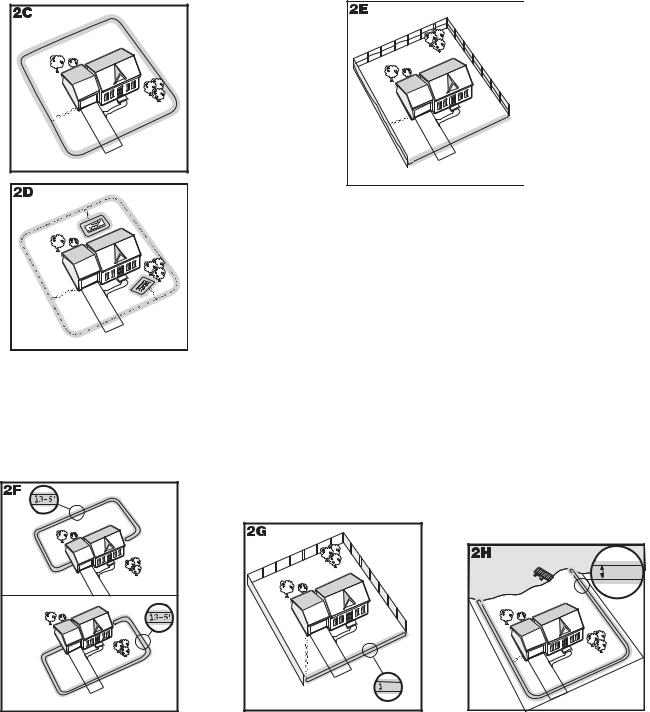
Sample Layouts
Sample 1: Perimeter Loop (Single Loop)
The Perimeter Loop is the most common layout.This will allow your pet to freely and safely roam your entire property (2C). It can also protect
gardens, pools and landscaping (2D).
C |
B |
D |
A |
E |
Sample 2 (2E): Perimeter Loop Using Existing Fence (Single Loop)
This layout allows you to include your existing fence as part of your layout and keep your pet from jumping out or digging under your existing fence. It reduces the amount of wire which will need to be buried. From the
Fence Transmitter, run the wire to A, A to B, B to C, C to D, D to E, E to A, twist the wires from A back to the Fence Transmitter. See the “Install the Boundary Wire” section for more information on attaching the wire to a fence.
Double Loop
A Double Loop must be used when you are not establishing the Boundary Zone on all sides of your property.
When using a Double Loop, the Boundary Wire must be separated by a minimum of 3 TO 5 FEET to avoid canceling the signal. Remember that a Double Loop will require twice as much wire.
|
D |
|
C |
|
E |
|
|
F |
B |
A |
|
|
F |
E |
A |
|
|
B |
|
D |
|
|
|
C |
|
|
Sample 3 (2F): Front or Back |
||
Yard Only (Double Loop)
From the Fence Transmitter, run the wire to A, A to B, B to C, C to D, D to E, E to F, make a U-turn and follow your path all the way back to A, keeping the wire separated 3 to 5 feet.Twist the wire from A back to the Fence Transmitter.
|
B |
A |
3-5' |
|
|
Sample 4 (2G): Front |
|
Boundary Only
(Double Loop)
From the Fence Transmitter, run the wire to A, A to B, B back to A keeping the wire separated 3 to 5 feet.Twist the wire from A back to the Fence Transmitter.
|
E |
3-5' |
|
|
|
B |
|
|
A |
|
D |
|
C |
|
Sample 5 (2H): Lake Access |
||
(Double Loop)
From the Fence Transmitter, run the wire to A, A to B, make a U-turn and go to C, C to D, D to E, make a U-turn and follow your path all the way back to A keeping wire separated 3 to 5 feet.Twist the wire from A back to the Fence Transmitter.
6 |
1-800-732-2677 |
 Loading...