

Page 1

Perkins 4000 Series
4006-23 TAG1A, TAG2A and TAG3A Inline diesel engine
WORKSHOP MANUAL
6 cylinder turbo charged diesel eng ine for electric pow er
applications
Publication TPD 1511E, Issue 1.
© Proprietary information of Perkins Engines Company Limited, all rights reserved.
The information is correct at the time of print.
Published in September 2004 by Technical Publications.
Perkins Engine Company Limited, Peterborough PE1 5NA England
i
Page 2
This publication is written in
Perkins A pp rove d C lea r En glish
Chapters
1 General information
2 Specifications
3 Cylinder head assembly
4 Piston and connecting rod assemblies
5 Crankshaft assembly
6 Timing case and drive assembly
7 Cylinder block assembly
8 Engine timing
9 Aspiration system
10 Lubrication system
11 Fuel system
12 Cooling system
13 Flywheel and housing
14 Electrical equipment
15 Auxiliary equipment
16 Special tools
The following pages contain a detailed table of contents
ii
Page 3

4000 Series
Contents
1 General information
Introduction .. ... ... ... ... ... ... ... ... ... ... ... ... ... ... ... ... ... ... ... ... ... ... ... ... ... ... ... ... ... ... ... ... ... ... ... 1
Engine views ... ... ... ... ... ... ... ... ... ... ... ... ... ... ... ... ... ... ... ... ... ... ... ... ... ... ... ... ... ... ... ... ... ... ... 2
Engine identification . ... ... ... ... ... ... ... ... ... ... ... ... ... ... ... ... ... ... ... ... ... ... ... ... ... ... ... ... ... ... ... 3
General safety precautions ... ... ... ... ... ... ... ... ... ... ... ... ... ... ... ... ... ... ... ... ... ... ... ... ... ... ... ... 4
Viton seals . ... ... ... ... ... ... ... ... ... ... ... ... ... ... ... ... ... ... ... ... ... ... ... ... ... ... ... ... ... ... ... ... ... ... ... ... 5
Engine lift equipment ... ... ... ... ... ... ... ... ... ... ... ... ... ... ... ... ... ... ... ... ... ... ... ... ... ... ... ... ... ... ... 6
POWERPAR T reco mmen ded consu ma ble pr od uct s ... ... ... ... ... ... ... ... ... ... ... ... ... ... ... ... 7
2 Spec if ic at i o ns
Basic engine data . ... ... ... ... ... ... ... ... ... ... ... ... ... ... ... ... ... ... ... ... ... ... ... ... ... ... ... ... ... ... ... ... 9
Data and dimensions ... ... ... ... ... ... ... ... ... ... ... ... ... ... ... ... ... ... ... ... ... ... ... ... ... ... ... ... ... ... ..10
3 Cylinder head assembly
General description ... ... ... ... ... ... ... ... ... ... ... ... ... ... ... ... ... ... ... ... ... ... ... ... ... ... ... ... ... ... ... ..17
Rocker box and valve gear
Operation 3-1 To remove and fit the rocker box and valve gear ... ... ... ... ... ... ... ... ... ... ... ..18
Valve gear
Operation 3-2 To inspect rockers, bridge pieces and rocker shaft ... ... ... ... ... ... ... ... ... ... ..20
Workshop Manual, TPD 1511E, issue 1 iii
Page 4

4000 Series
Operation 3-3 To replace the bridge piece pressure pad .. ... ... ... ... ... ... ... ... ... ... ... ... ... ... 21
Cylinder head
Operation 3-4 To remove and fit the cylinder head . ... ... ... ... ... ... ... ... ... ... ... ... ... ... ... ... ... 22
Valves and springs
Operation 3-5 To remove and fit the valve and the valve springs .. ... ... ... ... ... ... ... ... ... ... 24
Operation 3-6 To inspect . ... ... ... ... ... ... ... ... ... ... ... ... ... ... ... ... ... ... ... ... ... ... ... ... ... ... ... ... ... 26
Valves seats
Operation 3-7 To remove and fit, and reface the valve seats .. ... ... ... ... ... ... ... ... ... ... ... ... 27
Valves guides
Operation 3-8 To remove and fit the valve guides ... ... ... ... ... ... ... ... ... ... ... ... ... ... ... ... ... ... 28
Fuel injector bush
Operation 3-9 To remove and fit a fuel injector bush .. ... ... ... ... ... ... ... ... ... ... ... ... ... ... ... ... 29
Cylinder head
Operation 3-10 To inspect and pressure test ... ... ... ... ... ... ... ... ... ... ... ... ... ... ... ... ... ... ... ... 33
Manifolds
Operation 3-11 To remove and fit the induction manifold . ... ... ... ... ... ... ... ... ... ... ... ... ... ... 34
Operation 3-12 To remove and fit the exhaust manifold ... ... ... ... ... ... ... ... ... ... ... ... ... ... ... 35
4 Piston and connecting rod assemblies
General description . ... ... ... ... ... ... ... ... ... ... ... ... ... ... ... ... ... ... ... ... ... ... ... ... ... ... ... ... ... ... ... 39
Piston and connecting rod
Operation 4-1 To remove ... ... ... ... ... ... ... ... ... ... ... ... ... ... ... ... ... ... ... ... ... ... ... ... ... ... ... ... ... 40
Operati on 4-2 To fit ... ... ... ... ... ... ... ... ... ... ... ... ... ... ... ... ... ... ... ... ... ... ... ... ... ... ... ... ... ... ... ... 43
Piston rings
Operation 4-3 To remove ... ... ... ... ... ... ... ... ... ... ... ... ... ... ... ... ... ... ... ... ... ... ... ... ... ... ... ... ... 45
Operati on 4-4 To fit ... ... ... ... ... ... ... ... ... ... ... ... ... ... ... ... ... ... ... ... ... ... ... ... ... ... ... ... ... ... ... ... 46
Piston and connecting rod assembly
Operation 4-5 To dismantle ... ... ... ... ... ... ... ... ... ... ... ... ... ... ... ... ... ... ... ... ... ... ... ... ... ... ... ... 47
Operation 4-6 To assemble ... ... ... ... ... ... ... ... ... ... ... ... ... ... ... ... ... ... ... ... ... ... ... ... ... ... ... ... 47
Piston and piston rings
Operation 4-7 To inspect . ... ... ... ... ... ... ... ... ... ... ... ... ... ... ... ... ... ... ... ... ... ... ... ... ... ... ... ... ... 49
Connecting rod
Operation 4-8 To inspect . ... ... ... ... ... ... ... ... ... ... ... ... ... ... ... ... ... ... ... ... ... ... ... ... ... ... ... ... ... 50
iv Workshop Manual, TPD 1511E, issue 1
Page 5

4000 Series
Small end bush
Operation 4-9 To inspect .. ... ... ... ... ... ... ... ... ... ... ... ... ... ... ... ... ... ... ... ... ... ... ... ... ... ... ... ... ..51
Operation 4-10 To remove and fit .. ... ... ... ... ... ... ... ... ... ... ... ... ... ... ... ... ... ... ... ... ... ... ... ... ..51
Piston cooling jets
Operation 4-11 To remove .. ... ... ... ... ... ... ... ... ... ... ... ... ... ... ... ... ... ... ... ... ... ... ... ... ... ... ... ..52
Operation 4-12 To fit .. ... ... ... ... ... ... ... ... ... ... ... ... ... ... ... ... ... ... ... ... ... ... ... ... ... ... ... ... ... ... ..53
5 Crankshaft assembly
General description ... ... ... ... ... ... ... ... ... ... ... ... ... ... ... ... ... ... ... ... ... ... ... ... ... ... ... ... ... ... ... ..55
Crankshaft pulley and adaptor
Operation 5-1 To remove .. ... ... ... ... ... ... ... ... ... ... ... ... ... ... ... ... ... ... ... ... ... ... ... ... ... ... ... ... ..56
Operation 5-2 To fit . ... ... ... ... ... ... ... ... ... ... ... ... ... ... ... ... ... ... ... ... ... ... ... ... ... ... ... ... ... ... ... .. 57
Crankshaft vibration damper assembly
Operation 5-3 To remove .. ... ... ... ... ... ... ... ... ... ... ... ... ... ... ... ... ... ... ... ... ... ... ... ... ... ... ... ... ..58
Operation 5-4 To fit . ... ... ... ... ... ... ... ... ... ... ... ... ... ... ... ... ... ... ... ... ... ... ... ... ... ... ... ... ... ... ... .. 59
Crankshaft
Operation 5-5 To remove ... ... ... ... ... ... ... ... ... ... ... ... ... ... ... ... ... ... ... ... ... ... ... ... ... ... ... ... ..60
Operation 5-6 To fit . ... ... ... ... ... ... ... ... ... ... ... ... ... ... ... ... ... ... ... ... ... ... ... ... ... ... ... ... ... ... ... .. 61
Operation 5-7 To check the crankshaft end float ... ... ... ... ... ... ... ... ... ... ... ... ... ... ... ... ... ... ..63
6 Gearcase and drive assembly
General description ... ... ... ... ... ... ... ... ... ... ... ... ... ... ... ... ... ... ... ... ... ... ... ... ... ... ... ... ... ... ... ..65
Gearcase
Operation 6-1 To remove .. ... ... ... ... ... ... ... ... ... ... ... ... ... ... ... ... ... ... ... ... ... ... ... ... ... ... ... ... ..66
Operation 6-2 To fit . ... ... ... ... ... ... ... ... ... ... ... ... ... ... ... ... ... ... ... ... ... ... ... ... ... ... ... ... ... ... ... .. 67
Front oil seal
Operation 6-3 To remove .. ... ... ... ... ... ... ... ... ... ... ... ... ... ... ... ... ... ... ... ... ... ... ... ... ... ... ... ... ..68
Operation 6-4 To fit . ... ... ... ... ... ... ... ... ... ... ... ... ... ... ... ... ... ... ... ... ... ... ... ... ... ... ... ... ... ... ... .. 68
Camshaft gear
Operation 6-5 To remove .. ... ... ... ... ... ... ... ... ... ... ... ... ... ... ... ... ... ... ... ... ... ... ... ... ... ... ... ... ..69
Operation 6-6 To fit . ... ... ... ... ... ... ... ... ... ... ... ... ... ... ... ... ... ... ... ... ... ... ... ... ... ... ... ... ... ... ... .. 70
Idler gear
Operation 6-7 To remove .. ... ... ... ... ... ... ... ... ... ... ... ... ... ... ... ... ... ... ... ... ... ... ... ... ... ... ... ... ..71
Operation 6-8 To fit . ... ... ... ... ... ... ... ... ... ... ... ... ... ... ... ... ... ... ... ... ... ... ... ... ... ... ... ... ... ... ... .. 72
Operation 6-9 To check the hub and renew the idler gear bush ... ... ... ... ... ... ... ... ... ... ... ..73
Workshop Manual, TPD 1511E, issue 1 v
Page 6

4000 Series
Cam followers
Operation 6-10 To remove and fit . ... ... ... ... ... ... ... ... ... ... ... ... ... ... ... ... ... ... ... ... ... ... ... ... ... 74
Operation 6-11 To check ... ... ... ... ... ... ... ... ... ... ... ... ... ... ... ... ... ... ... ... ... ... ... ... ... ... ... ... ... 75
Camshaft
Operation 6-12 To remove .. ... ... ... ... ... ... ... ... ... ... ... ... ... ... ... ... ... ... ... ... ... ... ... ... ... ... ... ... 76
Operation 6-13 To check the camshaft .. ... ... ... ... ... ... ... ... ... ... ... ... ... ... ... ... ... ... ... ... ... ... 77
Operation 6-14 To fit . ... ... ... ... ... ... ... ... ... ... ... ... ... ... ... ... ... ... ... ... ... ... ... ... ... ... ... ... ... ... ... 78
Operation 6-15 To remove and fit the camshaft bush ... ... ... ... ... ... ... ... ... ... ... ... ... ... ... ... 79
Crankshaft gear
Operation 6-16 To remove .. ... ... ... ... ... ... ... ... ... ... ... ... ... ... ... ... ... ... ... ... ... ... ... ... ... ... ... ... 80
Operation 6-17 To fit . ... ... ... ... ... ... ... ... ... ... ... ... ... ... ... ... ... ... ... ... ... ... ... ... ... ... ... ... ... ... ... 81
Back Plate
Operation 6-18 To remove .. ... ... ... ... ... ... ... ... ... ... ... ... ... ... ... ... ... ... ... ... ... ... ... ... ... ... ... ... 82
Operation 6-19 To fit . ... ... ... ... ... ... ... ... ... ... ... ... ... ... ... ... ... ... ... ... ... ... ... ... ... ... ... ... ... ... ... 83
7 Crankc as e
General Description . ... ... ... ... ... ... ... ... ... ... ... ... ... ... ... ... ... ... ... ... ... ... ... ... ... ... ... ... ... ... ... 85
Crankcase
Operation 7-1 To remove ... ... ... ... ... ... ... ... ... ... ... ... ... ... ... ... ... ... ... ... ... ... ... ... ... ... ... ... ... 86
Operati on 7-2 To fit ... ... ... ... ... ... ... ... ... ... ... ... ... ... ... ... ... ... ... ... ... ... ... ... ... ... ... ... ... ... ... ... 87
Operation 7-3 To inspect . ... ... ... ... ... ... ... ... ... ... ... ... ... ... ... ... ... ... ... ... ... ... ... ... ... ... ... ... ... 87
Cylinder Liner
Operation 7-4 To inspect . ... ... ... ... ... ... ... ... ... ... ... ... ... ... ... ... ... ... ... ... ... ... ... ... ... ... ... ... ... 88
Operation 7-5 To remove ... ... ... ... ... ... ... ... ... ... ... ... ... ... ... ... ... ... ... ... ... ... ... ... ... ... ... ... ... 89
Operati on 7-6 To fit liner .. ... ... ... ... ... ... ... ... ... ... ... ... ... ... ... ... ... ... ... ... ... ... ... ... ... ... ... ... ... 90
8 Engine timing
Operation 8-1 To set number 1 piston to Top Dead Centre (TDC) ... ... ... ... ... ... ... ... ... ... 91
Operation 8-2 Calibrating fuel injectors .. ... ... ... ... ... ... ... ... ... ... ... ... ... ... ... ... ... ... ... ... ... ... 92
Operation 8-3 Setting governor on zero fuel . ... ... ... ... ... ... ... ... ... ... ... ... ... ... ... ... ... ... ... ... 94
Operation 8-4 Applying pressure to the timing pin .. ... ... ... ... ... ... ... ... ... ... ... ... ... ... ... ... ... 95
Operation 8-5 Timing the fuel injectors ... ... ... ... ... ... ... ... ... ... ... ... ... ... ... ... ... ... ... ... ... ... ... 96
9 Aspiration system
General description . ... ... ... ... ... ... ... ... ... ... ... ... ... ... ... ... ... ... ... ... ... ... ... ... ... ... ... ... ... ... ... 99
vi Workshop Manual, TPD 1511E, issue 1
Page 7

4000 Series
How to check the air restriction indicator
Operation 9-1 To check and reset . ... ... ... ... ... ... ... ... ... ... ... ... ... ... ... ... ... ... ... ... ... ... ... ... 100
Air filter element
Operation 9-2 To remove and fit ... ... ... ... ... ... ... ... ... ... ... ... ... ... ... ... ... ... ... ... ... ... ... ... ... 101
Air filter and pipe connection
Operation 9-3 To remove .. ... ... ... ... ... ... ... ... ... ... ... ... ... ... ... ... ... ... ... ... ... ... ... ... ... ... ... ... 102
Operation 9-4 To fit . ... ... ... ... ... ... ... ... ... ... ... ... ... ... ... ... ... ... ... ... ... ... ... ... ... ... ... ... ... ... ... 103
Air filter bracket
Operation 9-5 To remove .. ... ... ... ... ... ... ... ... ... ... ... ... ... ... ... ... ... ... ... ... ... ... ... ... ... ... ... ... 104
Operation 9-6 To fit . ... ... ... ... ... ... ... ... ... ... ... ... ... ... ... ... ... ... ... ... ... ... ... ... ... ... ... ... ... ... ... 104
Turbocharger ... ... ... ... ... ... ... ... ... ... ... ... ... ... ... ... ... ... ... ... ... ... ... ... ... ... ... ... ... ... ... ... ... ... 105
Operation 9-7 To remove ... ... ... ... ... ... ... ... ... ... ... ... ... ... ... ... ... ... ... ... ... ... ... ... ... ... ... ... 106
Operation 9-8 To fit ... ... ... ... ... ... ... ... ... ... ... ... ... ... ... ... ... ... ... ... ... ... ... ... ... ... ... ... ... ... ... 108
Air pipe connection
Operation 9-9 To remove ... ... ... ... ... ... ... ... ... ... ... ... ... ... ... ... ... ... ... ... ... ... ... ... ... ... ... ... 110
Operation 9-10 To fit . ... ... ... ... ... ... ... ... ... ... ... ... ... ... ... ... ... ... ... ... ... ... ... ... ... ... ... ... ... ... 111
Engine breather
Operation 9-11 To remove breather system ... ... ... ... ... ... ... ... ... ... ... ... ... ... ... ... ... ... ... ... 1 12
Operation 9-12 To fit the breather system ... ... ... ... ... ... ... ... ... ... ... ... ... ... ... ... ... ... ... ... ... 113
10 Lubrication system
General Description .. ... ... ... ... ... ... ... ... ... ... ... ... ... ... ... ... ... ... ... ... ... ... ... ... ... ... ... ... ... ... 115
Filter Canister
Operation 10-1 To renew .. ... ... ... ... ... ... ... ... ... ... ... ... ... ... ... ... ... ... ... ... ... ... ... ... ... ... ... ... 117
Filter head
Operation 10-2 To remove and to fit . ... ... ... ... ... ... ... ... ... ... ... ... ... ... ... ... ... ... ... ... ... ... ... 118
Lubricating oil sump
Operation 10-3 To remove ... ... ... ... ... ... ... ... ... ... ... ... ... ... ... ... ... ... ... ... ... ... ... ... ... ... ... ... 119
Operation 10-4 To fit .. ... ... ... ... ... ... ... ... ... ... ... ... ... ... ... ... ... ... ... ... ... ... ... ... ... ... ... ... ... ... 120
Dipstick tube
Operation 10-5 To remove and to fit . ... ... ... ... ... ... ... ... ... ... ... ... ... ... ... ... ... ... ... ... ... ... ... 121
Oil strainer and suction pipe
Operation 10-6 To remove and to fit . ... ... ... ... ... ... ... ... ... ... ... ... ... ... ... ... ... ... ... ... ... ... ... 122
Workshop Manual, TPD 1511E, issue 1 vii
Page 8

4000 Series
Lubricating oil pump
Operation 10-7 To remove .. ... ... ... ... ... ... ... ... ... ... ... ... ... ... ... ... ... ... ... ... ... ... ... ... ... ... ... ..123
Operation 10-8 To fit . ... ... ... ... ... ... ... ... ... ... ... ... ... ... ... ... ... ... ... ... ... ... ... ... ... ... ... ... ... ... ..124
Operation 10-9 To dismantle . ... ... ... ... ... ... ... ... ... ... ... ... ... ... ... ... ... ... ... ... ... ... ... ... ... ... ..125
Operation 10-10 To assemble ... ... ... ... ... ... ... ... ... ... ... ... ... ... ... ... ... ... ... ... ... ... ... ... ... ... ..126
Operation 10-11 To inspect ... ... ... ... ... ... ... ... ... ... ... ... ... ... ... ... ... ... ... ... ... ... ... ... ... ... ... .. 128
Relief Valve
Operation 10-12 To dismantle and to assemble .. ... ... ... ... ... ... ... ... ... ... ... ... ... ... ... ... ... ..129
Operation 10-13 To inspect ... ... ... ... ... ... ... ... ... ... ... ... ... ... ... ... ... ... ... ... ... ... ... ... ... ... ... .. 130
Fuel lift pump drive unit
Operation 10-14 To renew .. ... ... ... ... ... ... ... ... ... ... ... ... ... ... ... ... ... ... ... ... ... ... ... ... ... ... ... ..131
Rotor end float
Operation 10-15 To inspect ... ... ... ... ... ... ... ... ... ... ... ... ... ... ... ... ... ... ... ... ... ... ... ... ... ... ... .. 132
Drive shaft bearings
Operation 10-16 To remove and to fit . ... ... ... ... ... ... ... ... ... ... ... ... ... ... ... ... ... ... ... ... ... ... ..133
11 Fuel syste m
General description . ... ... ... ... ... ... ... ... ... ... ... ... ... ... ... ... ... ... ... ... ... ... ... ... ... ... ... ... ... ... ..135
Fuel filter
Operation 11-1 To remove and fit . ... ... ... ... ... ... ... ... ... ... ... ... ... ... ... ... ... ... ... ... ... ... ... ... ..136
Fuel injector unit
Operation 11-2 To remove the fuel injector unit .. ... ... ... ... ... ... ... ... ... ... ... ... ... ... ... ... ... .. 137
Operation 11-3 To disassemble and to check a fuel injector unit ... ... ... ... ... ... ... ... ... ... .. 139
Operation 11-4 To assemble the fuel injector unit ... ... ... ... ... ... ... ... ... ... ... ... ... ... ... ... ... ..143
To test and set the fuel injector
Operation 11-5 To test and set ... ... ... ... ... ... ... ... ... ... ... ... ... ... ... ... ... ... ... ... ... ... ... ... ... ..146
Operation 11-6 To fit a fuel injector .. ... ... ... ... ... ... ... ... ... ... ... ... ... ... ... ... ... ... ... ... ... ... ... ..151
Fuel Lift pump
Operation 11-7 To remove and to fit ... ... ... ... ... ... ... ... ... ... ... ... ... ... ... ... ... ... ... ... ... ... ... ..152
Fuel control shaft
Operation 11-8 To remove .. ... ... ... ... ... ... ... ... ... ... ... ... ... ... ... ... ... ... ... ... ... ... ... ... ... ... ... ..153
Operation 11-9 To inspect .. ... ... ... ... ... ... ... ... ... ... ... ... ... ... ... ... ... ... ... ... ... ... ... ... ... ... ... ..154
Operation 11-10 To fit .. ... ... ... ... ... ... ... ... ... ... ... ... ... ... ... ... ... ... ... ... ... ... ... ... ... ... ... ... ... ..155
viii Workshop Manual, TPD 1511E, issue 1
Page 9

4000 Series
12 Cooli ng syst e m
Coolant pipework
Operation 12-1 To remove and fit the coolant pipework . ... ... ... ... ... ... ... ... ... ... ... ... ... ... 1 58
Thermostat
Operation 12-2 To remove the thermostat .. ... ... ... ... ... ... ... ... ... ... ... ... ... ... ... ... ... ... ... ... 159
Operation 12-3 To fit the thermostat . ... ... ... ... ... ... ... ... ... ... ... ... ... ... ... ... ... ... ... ... ... ... ... 160
Operation 12-4 To test . ... ... ... ... ... ... ... ... ... ... ... ... ... ... ... ... ... ... ... ... ... ... ... ... ... ... ... ... ... 161
Thermostat housing
Operation 12-5 To remove and fit the thermostat housing . ... ... ... ... ... ... ... ... ... ... ... ... ... 162
Coolant pump
Operation 12-6 To remove the coolant pump . ... ... ... ... ... ... ... ... ... ... ... ... ... ... ... ... ... ... ... 164
Operation 12-7 To fit the coolant pump ... ... ... ... ... ... ... ... ... ... ... ... ... ... ... ... ... ... ... ... ... ... 166
Operation 12-8 To disassemble the coolant pump ... ... ... ... ... ... ... ... ... ... ... ... ... ... ... ... ... 168
Operation 12-9 To assemble the coolant pump . ... ... ... ... ... ... ... ... ... ... ... ... ... ... ... ... ... ... 1 69
Fan Guards
Operation 12-10 To remove and fit ... ... ... ... ... ... ... ... ... ... ... ... ... ... ... ... ... ... ... ... ... ... ... ... 171
Fan
Operation 12-11 To remove and fit ... ... ... ... ... ... ... ... ... ... ... ... ... ... ... ... ... ... ... ... ... ... ... ... 171
Fan drive belts
Operation 12-12 To check the fan drive belts . ... ... ... ... ... ... ... ... ... ... ... ... ... ... ... ... ... ... ... 172
Operation 12-13 To adjust the fan drive belts ... ... ... ... ... ... ... ... ... ... ... ... ... ... ... ... ... ... ... 1 72
Operation 12-14 To remove and fit the drive belts ... ... ... ... ... ... ... ... ... ... ... ... ... ... ... ... ... 173
Fan drive
Operation 12-15 To remove and fit ... ... ... ... ... ... ... ... ... ... ... ... ... ... ... ... ... ... ... ... ... ... ... ... 174
Lubricating oil cooler
Operation 12-16 To remove ... ... ... ... ... ... ... ... ... ... ... ... ... ... ... ... ... ... ... ... ... ... ... ... ... ... ... 176
Operation 12-17 To fit ... ... ... ... ... ... ... ... ... ... ... ... ... ... ... ... ... ... ... ... ... ... ... ... ... ... ... ... ... ... 177
Operation 12-18 To disassemble and clean the oil cooler tube stack . ... ... ... ... ... ... ... ... 178
Operation 12-19 To assemble the oil cooler tube stack .. ... ... ... ... ... ... ... ... ... ... ... ... ... ... 179
Operation 12-20 To pressure test the oil cooler ... ... ... ... ... ... ... ... ... ... ... ... ... ... ... ... ... ... 180
Radiator
Operation 12-21 To remove ... ... ... ... ... ... ... ... ... ... ... ... ... ... ... ... ... ... ... ... ... ... ... ... ... ... ... 181
Operation 12-22 To fit ... ... ... ... ... ... ... ... ... ... ... ... ... ... ... ... ... ... ... ... ... ... ... ... ... ... ... ... ... ... 182
Workshop Manual, TPD 1511E, issue 1 ix
Page 10

4000 Series
13 Flywheel and housing
General description . ... ... ... ... ... ... ... ... ... ... ... ... ... ... ... ... ... ... ... ... ... ... ... ... ... ... ... ... ... ... ..183
Flywheel
Operation 13-1 To remove and to fit the flywheel ... ... ... ... ... ... ... ... ... ... ... ... ... ... ... ... ... ..184
Gear ring
Operation 13-2 To remove and to fit the gear ring .. ... ... ... ... ... ... ... ... ... ... ... ... ... ... ... ... ..186
Flywheel Housing
Operation 13-3 To remove and to fit the flywheel housing ... ... ... ... ... ... ... ... ... ... ... ... ... ..187
Flywheel housing oil seal
Operation 13-4 To remove and to fit the flywheel housing oil seal . ... ... ... ... ... ... ... ... ... .. 189
14 Electrical equipment
General description . ... ... ... ... ... ... ... ... ... ... ... ... ... ... ... ... ... ... ... ... ... ... ... ... ... ... ... ... ... ... ..191
Alternator . ... ... ... ... ... ... ... ... ... ... ... ... ... ... ... ... ... ... ... ... ... ... ... ... ... ... ... ... ... ... ... ... ... ... ... ..192
Operation 14-1 To check the drive belts . ... ... ... ... ... ... ... ... ... ... ... ... ... ... ... ... ... ... ... ... ... ..192
Operation 14-2 To adjust the drive belt tension ... ... ... ... ... ... ... ... ... ... ... ... ... ... ... ... ... ... ..193
Operation 14-3 To remove the alternator ... ... ... ... ... ... ... ... ... ... ... ... ... ... ... ... ... ... ... ... ... ..193
Operation 14-4 Remove the alternator drive pulley ... ... ... ... ... ... ... ... ... ... ... ... ... ... ... ... ..194
Operation 14-5 To fit the alternator drive pulley ... ... ... ... ... ... ... ... ... ... ... ... ... ... ... ... ... ... ..195
Operation 14-6 To fit the alternator .. ... ... ... ... ... ... ... ... ... ... ... ... ... ... ... ... ... ... ... ... ... ... ... ..196
Operation 14-7 To maintain ... ... ... ... ... ... ... ... ... ... ... ... ... ... ... ... ... ... ... ... ... ... ... ... ... ... ... ..196
Starter motor .. ... ... ... ... ... ... ... ... ... ... ... ... ... ... ... ... ... ... ... ... ... ... ... ... ... ... ... ... ... ... ... ... ... ..197
Operation 14-8 To remove ... ... ... ... ... ... ... ... ... ... ... ... ... ... ... ... ... ... ... ... ... ... ... ... ... ... ... .. 197
Operation 14-9 To Fit .. ... ... ... ... ... ... ... ... ... ... ... ... ... ... ... ... ... ... ... ... ... ... ... ... ... ... ... ... ... .. 197
The air starter motor system ... ... ... ... ... ... ... ... ... ... ... ... ... ... ... ... ... ... ... ... ... ... ... ... ... ... ..198
Operation 14-10 To remove .. ... ... ... ... ... ... ... ... ... ... ... ... ... ... ... ... ... ... ... ... ... ... ... ... ... ... ..201
Operation 14-11 To fit . ... ... ... ... ... ... ... ... ... ... ... ... ... ... ... ... ... ... ... ... ... ... ... ... ... ... ... ... ... ..201
Stop solenoid
Operation 14-12 To remove .. ... ... ... ... ... ... ... ... ... ... ... ... ... ... ... ... ... ... ... ... ... ... ... ... ... ... ..202
Operation 14-13 To fit . ... ... ... ... ... ... ... ... ... ... ... ... ... ... ... ... ... ... ... ... ... ... ... ... ... ... ... ... ... ..202
Digital Electronic Governor . ... ... ... ... ... ... ... ... ... ... ... ... ... ... ... ... ... ... ... ... ... ... ... ... ... ... ..203
Description of System ... ... ... ... ... ... ... ... ... ... ... ... ... ... ... ... ... ... ... ... ... ... ... ... ... ... ... ... ... ..206
Block diagram of the governor system ... ... ... ... ... ... ... ... ... ... ... ... ... ... ... ... ... ... ... ... ... ..207
x Workshop Manual, TPD 1511E, issue 1
Page 11

4000 Series
Magnetic pick-up
Operation 14-14 To clean the magnetic pick-up ... ... ... ... ... ... ... ... ... ... ... ... ... ... ... ... ... ... 2 08
Operation 14-15 To remove the actuator . ... ... ... ... ... ... ... ... ... ... ... ... ... ... ... ... ... ... ... ... ... 209
Operation 14-16 To fit ... ... ... ... ... ... ... ... ... ... ... ... ... ... ... ... ... ... ... ... ... ... ... ... ... ... ... ... ... ... 2 10
Specification of Governor system ... ... ... ... ... ... ... ... ... ... ... ... ... ... ... ... ... ... ... ... ... ... ... ... 2 11
Operation 14-17 To remove the digital control box ... ... ... ... ... ... ... ... ... ... ... ... ... ... ... ... ... 211
Operation 14-18 To Fit the digital control box ... ... ... ... ... ... ... ... ... ... ... ... ... ... ... ... ... ... ... 2 11
Feedback Setting
Operation 14-19 To adjust ... ... ... ... ... ... ... ... ... ... ... ... ... ... ... ... ... ... ... ... ... ... ... ... ... ... ... ... 212
Configuration ... ... ... ... ... ... ... ... ... ... ... ... ... ... ... ... ... ... ... ... ... ... ... ... ... ... ... ... ... ... ... ... ... ... 216
External Speed Control Input ... ... ... ... ... ... ... ... ... ... ... ... ... ... ... ... ... ... ... ... ... ... ... ... ... ... 216
Changing the governor configuration ... ... ... ... ... ... ... ... ... ... ... ... ... ... ... ... ... ... ... ... ... ... 217
Operation 14-20 To adjust ... ... ... ... ... ... ... ... ... ... ... ... ... ... ... ... ... ... ... ... ... ... ... ... ... ... ... ... 217
Single/Parallel Generator (Non Heinzmann Load Sharing)
Operation 14-21 To adjust ... ... ... ... ... ... ... ... ... ... ... ... ... ... ... ... ... ... ... ... ... ... ... ... ... ... ... ... 218
Single/Parallel Generator with Droop
Operation 14-22 To adjust ... ... ... ... ... ... ... ... ... ... ... ... ... ... ... ... ... ... ... ... ... ... ... ... ... ... ... ... 219
Parallel Generator Heinzmann (SyG02/LMG10-01)
Operation 14-23 To adjust ... ... ... ... ... ... ... ... ... ... ... ... ... ... ... ... ... ... ... ... ... ... ... ... ... ... ... ... 220
Parallel Generator Heinzmann Digital Theseus
Operation 14-24 To adjust ... ... ... ... ... ... ... ... ... ... ... ... ... ... ... ... ... ... ... ... ... ... ... ... ... ... ... ... 221
Parallel Generator Variable Speed in Droop Range
Operation 14-25 To adjust ... ... ... ... ... ... ... ... ... ... ... ... ... ... ... ... ... ... ... ... ... ... ... ... ... ... ... ... 222
Other settings
Operation 14-26 Load Control Settings ... ... ... ... ... ... ... ... ... ... ... ... ... ... ... ... ... ... ... ... ... ... 223
PID parameters
Operation 14-27 To adjust ... ... ... ... ... ... ... ... ... ... ... ... ... ... ... ... ... ... ... ... ... ... ... ... ... ... ... ... 226
PID Maps
Operation 14-28 To adjust ... ... ... ... ... ... ... ... ... ... ... ... ... ... ... ... ... ... ... ... ... ... ... ... ... ... ... ... 227
Speed Ramps ... ... ... ... ... ... ... ... ... ... ... ... ... ... ... ... ... ... ... ... ... ... ... ... ... ... ... ... ... ... ... ... ... ... 2 28
Sectional Speed Ramp
Operation 14-29 To adjust ... ... ... ... ... ... ... ... ... ... ... ... ... ... ... ... ... ... ... ... ... ... ... ... ... ... ... ... 229
Workshop Manual, TPD 1511E, issue 1 xi
Page 12

4000 Series
External connections – Control box connector ... ... ... ... ... ... ... ... ... ... ... ... ... ... ... ... ... ..234
Alternative Connections for Speed Setting Inputs . ... ... ... ... ... ... ... ... ... ... ... ... ... ... ... ..235
Wiring detail, digital control box in IP enclosure – production engines ... ... ... ... ... ..236
Fault Tracing ... ... ... ... ... ... ... ... ... ... ... ... ... ... ... ... ... ... ... ... ... ... ... ... ... ... ... ... ... ... ... ... ... ... ..237
Error Codes . ... ... ... ... ... ... ... ... ... ... ... ... ... ... ... ... ... ... ... ... ... ... ... ... ... ... ... ... ... ... ... ... ... ... ..239
Low oil High water temperature switch ... ... ... ... ... ... ... ... ... ... ... ... ... ... ... ... ... ... ... ... ... ..242
Operation 14-30 To remove ... ... ... ... ... ... ... ... ... ... ... ... ... ... ... ... ... ... ... ... ... ... ... ... ... ... ... ..242
Operation 14-31 To fit .. ... ... ... ... ... ... ... ... ... ... ... ... ... ... ... ... ... ... ... ... ... ... ... ... ... ... ... ... ... ..242
Switch connections
Operation 14-32 To remove and fit .. ... ... ... ... ... ... ... ... ... ... ... ... ... ... ... ... ... ... ... ... ... ... ... ..243
Switch setting ... ... ... ... ... ... ... ... ... ... ... ... ... ... ... ... ... ... ... ... ... ... ... ... ... ... ... ... ... ... ... ... ... ..243
15 Auxiliary equipment
Operation 15-1 To remove .. ... ... ... ... ... ... ... ... ... ... ... ... ... ... ... ... ... ... ... ... ... ... ... ... ... ... ... ..246
Operation 15-2 To fit . ... ... ... ... ... ... ... ... ... ... ... ... ... ... ... ... ... ... ... ... ... ... ... ... ... ... ... ... ... ... ..247
Operation 15-3 To remove .. ... ... ... ... ... ... ... ... ... ... ... ... ... ... ... ... ... ... ... ... ... ... ... ... ... ... ... ..249
Operation 15-4 To fit . ... ... ... ... ... ... ... ... ... ... ... ... ... ... ... ... ... ... ... ... ... ... ... ... ... ... ... ... ... ... ..250
16 Special tools
List of special tools ... ... ... ... ... ... ... ... ... ... ... ... ... ... ... ... ... ... ... ... ... ... ... ... ... ... ... ... ... ... .. 252
xii Workshop Manual, TPD 1511E, issue 1
Page 13

4000 Series
1
General information 1
Introduction
This Workshop Manual has been written to provide assistance in the service and overhaul of
Perkins 4006-23, TAG1A, TAG2A and TAG3A engines. It should be used in conjunction with normal workshop
practise and information contained in current service bulletins. Mention of certain accepted practices therefore,
has been purposely omitted in order to avoid repetition. For overhaul procedures the assumption is made that
the engine is removed from the application.
The engine conf orms with USA (EPA/CARB) stage 2 and EEC stage 2 emissions legislation for agriculture,
construction and industrial applications.
Most of the general information which is included in the relevant User's Handbook has not been repeated in
this workshop manual and the two publications should be used together.
Where the information applies only to certain engine types, this is indicated in the text.
When reference is made to the "left" or "right" side of the engine, this is as seen from the flywheel end of the
engine.
When not working on the engine, ensure that all covers, blank flanges, doors, etc., are refitted to openings to
prevent the ingress of dirt, etc.
Please quote the engine type and serial number with all your enquiries. This will help us to help you. The type
and serial number are on a plate fitted to the crankcase.
If any doubt exists regarding the installation, use or application of the engine, the Installation Manual should
be consulted for further advice contact Applications Department at Perkins Engines (Stafford) Ltd.
Oil change intervals may be changed according to operating experience by agreement with Perkins Engines
(Stafford) Limited and subject to oil analysis being carried out at regular intervals.
Special tools have been made available and a list of these is given in Chapter 16, Special tools. Reference to
the relevant special tools is also made at the beginning of each operation.
POWERPART recommend ed consumab le products are listed under "P OW E RPART recomm ended
consumable products" on page 7. Reference to the relevant consumable products is also made at the
beginning of each operation.
Data and dimensions are included in Chapter 2, Specifications.
Read and remember the "General safety precautions" on page 4. They are given for your protection and must
be used at all times.
Danger is indicated in the text by two methods:
Warning! This indicates that there is a possible danger to the person.
Caution: This indicates that there is a possible danger to the engine.
Note: Is used where the information is important, but there is not a danger.
Workshop Manual, TPD 1511E, issue 1 1
Page 14
1
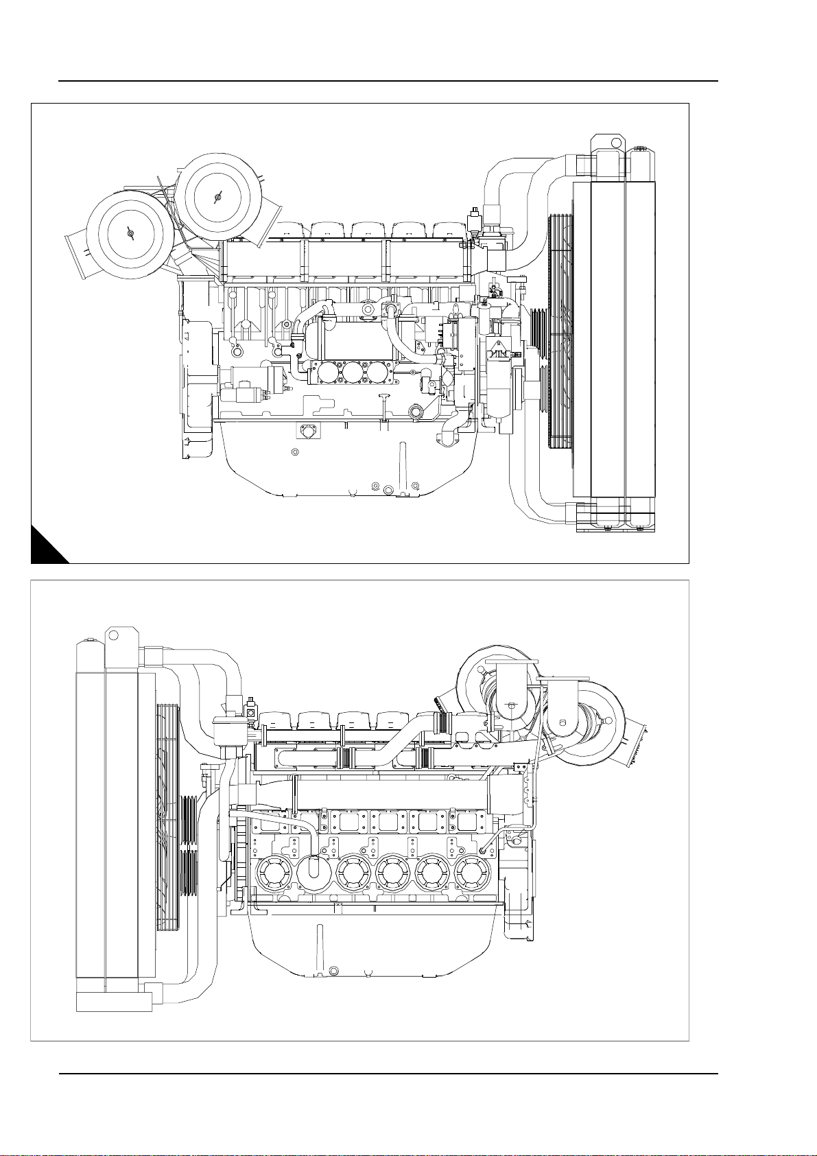
Engine views
4000 Series
JC
A
D1001
D1367
2 Workshop Manual, TPD 1511E, issue 1
Page 15

4000 Series
Engine identification
The 4006-23 engine consists of a range of six cylinder engines. This range has three basic engine types,
TAG1A, TAG2A and TAG3A.
The different engines are identified by their engine number and their type as shown below:
A typical example of an engine number: DGB 060081 U0017 B
Engine number identification
D Made in Stafford
G Application code
B Engine type
06 Number of cylinders
0081 Fixed build number
U United Kingdom
0017 Number of engines bui lt
B Year that the engine was built
Engine type
A 4006-23TAG1A
B 4006-23TAG2A
D 4006-23TAG3A
1
The position of the plate for the engine number (A1).
1
A
D1104
Workshop Manual, TPD 1511E, issue 1 3
Page 16

1
4000 Series
General safety precautions
These safety precautions are important. You must refer also to the local regulations in the country of use.
Some items only refer to specific applications.
Only use these engines in the type of application for which they have been designed.
Do not change the specification of the engine.
Do not smoke when you put fuel in the tank.
Clean away fuel which has been spilt. Material which has been contaminated by fuel must be moved to a
safe place.
Do not put fuel in the tank while the engine runs (unless it is absolutely necessary).
Do not allow sparks or fire near the batteries (especially when the batteries are on charge) because the
gases from the electrolyte are highly flammable. The battery fluid is dangerous to the skin and especially
to the e yes.
Do not smoke when you are in the working area of the engine.
Isolate the engine and disconnect the battery before a repair is made to the electrical system.
Do not clean, add lubricating oil, or adjust the engine while it runs (unless you have had the correct training,
even then extreme care must be used to prevent injury).
Do not make adjustments that you do not understand.
Ensure that the engine does not run in a location where it can cause a concentration of toxic emissions.
Ensure that the exhaust system from the engine is supported.
Other persons must be kept at a safe distance while the engine or auxiliary equipment is in operation.
Do not permit loose clothing or long hair near moving parts.
Keep away from moving parts during engine operation.
Warning! Some moving parts cannot be seen clearly while the engine runs.
Do not operate the engine if a safety guard has been removed.
Do not remove the filler cap or any component of the cooling system while the engine is hot and while the
coolant is under pressure, because dangerous hot coolant can be discharged.
Only one person must control the engine.
Ensure that the engine is operated only from the control panel or from the operator’s position.
If your skin comes into contact with high-pressure fuel, obtain medical assistance immediately.
Diesel fuel and lubricating oil (especially used lubricating oil) can damage the skin of certain persons.
Protect your hands with gloves or a special solution to protect the skin.
Ensure that all personal protection equipment for your head, ears, eyes and feet etc, are used when you
are in the working area of the engine.
Do not wear clothing which is contaminated by lubricating oil. Do not put material which is contaminated
with oil into the pockets of clothing.
Discard used lubricating oil in accordance with local regulations to prevent contamination.
Ensure that the control lever of the transmission drive is in the "out-of-drive" position before the engine is
started.
Use extreme care if emergency repairs must be made in adverse conditions.
The combustible material of some components of the engine (for example certain seals) can become
extremely dangerous if it is burned. Never allow this burnt material to come into contact with the skin or with
the eyes.
Always use a safety cage to protect the operator when a component is to be pressure tested in a container
of water. Fit safety wires to secure the plugs which seal the hose connections of a component which is to
be pressure tested.
Continued
4 Workshop Manual, TPD 1511E, issue 1
Page 17

4000 Series
C
Do not allow compressed air to contact your skin. If compressed air enters your skin, obtain medical help
immediately.
Turbochargers operate at high speed and at high temperatures. Keep fingers, tools and debris away from
the inlet and outlet ports of the turbocharger and prevent contact with hot surfaces.
Fit only genuine Perkins parts, failure to do so can damage the engine and may effect the warranty.
Do not wash an engine while it runs or while it is hot. If cold cleaning fluids are applied to a hot engine,
certain components on the engine could be damaged.
Always use lift equipment of the approved type and of the correct capacity to lift heavy engine components.
Never work alone when you operate lift equipment.
1
Viton seals
Viton is used by many manufacturers and is a safe material under normal conditions of operation.
Some seals used in engines and in components fitted to these engines are made of Viton.
If Viton is burned, a product of this burnt material is an acid which is extremely dangerous. Never allow this
burnt material to come into contact with the skin or with the eyes.
If it is necessary to come into contact with components which have been burnt, ensure that the precautions
which follow are used:
Ensure that the components have cooled.
Use neoprene gloves and discard the gloves safely after use.
Wash the area with calcium hydroxide solution and then with clean water.
Disposal of components and gloves which are contaminated must be in accordance with local regulations.
If there is contamination of the skin or eyes, wash the affected area with a continuous supply of clean water or
with calcium hydroxide solution for 15 to 60 minutes. Obtain immediate medical attention.
Safety cautions when an engine is cleaned
Care should be taken, when an engine is cleaned with a high pressure cleaning system.
autions:
Do not wash an engine while it runs or while it is hot. If cold cleaning fluids are applied to a hot engine,
certain components on the engine could be damaged.
Leave the engine to cool for at least one hour and disconnect the battery connections before cleaning.
Do not wash any part of the fuel injection pump (FIP), cold start device, electrical shut off solenoid (ESOS)
or electrical connectors.
Ensure that the alternator, starter motor and any other electrical components are shielded and not directly
cleaned by the high pressure cleaning system.
If these cautions are ignored, the engine or certain components could be damaged, fail to operate and also
make the manufacturer’s warranty invalid.
Workshop Manual, TPD 1511E, issue 1 5
Page 18

1
4
4000 Series
Engine lift equipment
When lifting engine or generating sets, special lifting equipment is required. It is recommended that a spreader
lifting beam of the correct lifting load capacity is used and that chains, hooks, shackles and eye bolts etc. are
checked that they are well within their safe working loads. The load should be secure, stable and balanced
when lifting.
The lifting chains etc must be firmly secured to the load by means of hooks etc on to the purpose-designed
lifting points, and that included angle is not exceeded (A).
In order to accommodate the chains for lifting it may be necessary to have to remove engine components such
as air filters etc to prevent damage, but this should be avoided where the chains can be clear by nondetrimental means.
Warning! Lifting equipment should be used by trained personnel only. Generating sets mu st be lifted using
the lifting lugs on the engine frame and a spreader lifting beam. The engine lifting brackets and alternator lifting
lugs must not be used.
A
6 Workshop Manual, TPD 1511E, issue 1
D114
Page 19

4000 Series
1
POWERPAR T reco mmen ded consu ma ble pr od uct s
Perkins have made available the products recommended below in order to assist in the correct operation,
service and maintenance of your engine and your machine. The instructions for the use of each product are
given on the outside of each container. These products are available from your Perkins distributor.
POWERPART ELC (Extended Life Coolant).
ELC is pre-mixed and protects the cooling system against frost and corrosion. Part number 21820181.
POWERPART Easy flush
Cleans the cooling system. Part number 21825001.
POWERPART Gasket and flange sealant
To seal flat faces of components where no joint is used. Especially suitable for aluminium components.
Part number 21820518.
POWERPART Gasket remover
An aerosol for the removal of sealants and adhesives. Part number 21820116.
POWERPART Griptite
To improve the grip of worn tools and fasteners. Part number 21820129.
POWERPART Hydraulic threadseal
(1)
To retain and seal pipe connections with fine threads. Especially suitable for hydraulic and pneumatic systems.
Part number 21820121.
POWERPART Industrial grade super glue
Instant adhesive designed for metals, plastics and rubbers. Part number 21820125.
POWERPART Lay-Up 1
A diesel fuel additive for protection against corrosion. Part number 1772204.
POWERPART Lay-Up 2
Protects the inside of the engine and of oth er closed systems. Part number 1762811.
POWERPART Lay-Up 3
Protects outside metal parts. Part number 1734115.
POWERPART Metal repair putty
Designed for external repair of metal and plastic. Part number 21820126.
POWERPART Pipe sealant and sealant primer
To retain and seal pipe connections with coarse threads. Pressure systems can be used immediately.
Part number 21820122.
Continued
Workshop Manual, TPD 1511E, issue 1 7
Page 20

1
POWERPART Radiator stop leak
For the repair of radiator leaks. Part number 21820127.
POWERPART Retainer (high strength)
To retain components which have an interference fit. Part number 21820638.
POWERPART Retainer (oil tolerant)
To retain components which have an interference fit, but are in contact with oil. Part number 21820608.
POWERPART Safety cleaner
General cleaner in an aerosol container. Part number 21820128.
POWERPART Silicone adhesive
4000 Series
An RTV silicone adhesive for application where low pressure tests occur before the adhesive sets. Used for
sealing flange where oil resistance is needed and movement of the joint occurs. Part number 21826038.
POWERPART Silicone RTV sealing and jointing compound
Silicone rubber sealant which prevents leakage through gaps. Part number 1861108.
POWERPART Stud and bearing lock
To provide a heavy duty seal to components that have a light interference fit. Part number 21820119 or
21820120.
POWERPART Threadlock and nutlock
To retain small fasteners where easy removal is necessary. Part number 21820117 or 21820118.
POWERPART Universal jointing compound
Universal jointing compound which seals joints. Part number 1861117.
(1) Powerpart (ELC) is not recommended for the 1300 Series.
(2) These product must not be used for the 4006-23 engine.
(2)
(2)
(2)
8 Workshop Manual, TPD 1511E, issue 1
Page 21

4000 Series
2
Specifications 2
Basic engine data
Number of cylinders. ... ... ... ... ... ... ... ... ... ... ... ... ... ... ... ... ... ... ... ... ... ... ... ... ... ... ... ... ... ... ... ... ... ... 6
Cylinder arrangement.. ... ... ... ... ... ... ... ... ... ... ... ... ... ... ... ... ... ... ... ... ... ... ... ... ... ... ... ...Ver ti c a l, in-l ine
Cycle ... ... ... ... ... ... ... ... ... ... ... ... ... ... ... ... ... ... ... ... ... ... ... ... ... ... ... ... ... ... ... ... ... ... ... ... Four stroke
Induction system.. ... ... ... ... ... ... ... ... ... ... ... ... ... ... ... .Turbocharged, air cooled C.A. in radiator (air to air)
Combustion system. ... ... ... ... ... ... ... ... ... ... ... ... ... ... ... ... ... ... ... ... ... ... ... ... ... ... ... ... ...Direct injection
Nominal bore... ... ... ... ... ... ... ... ... ... ... ... ... ... ... ... ... ... ... ... ... ... ... ... ... ... ... ... ... ... ... ... ... ... .160 mm
Nominal stroke. ... ... ... ... ... ... ... ... ... ... ... ... ... ... ... ... ... ... ... ... ... ... ... ... ... ... ... ... ... ... ... ... ... .190 mm
Compression ratio ... ... ... ... ... ... ... ... ... ... ... ... ... ... ... ... ... ... ... ... ... ... ... ... ... ... ... ... ... ... ... ... ... ...13:1
Cubic capacity . ... ... ... ... ... ... ... ... ... ... ... ... ... ... ... ... ... ... ... ... ... ... ... ... ... ... ... ... ... ... ... ... .22,92 litres
Firing order.. ... ... ... ... ... ... ... ... ... ... ... ... ... ... ... ... ... ... ... ... ... ... ... ... ... ... ... ... ... ... ... ... 1, 5, 3, 6, 2, 4
Direction of rotation . ... ... ... ... ... ... ... ... ... ... ... ... ... ... ... ... ... ... ... ... ... Anti-clockwise viewed on flywheel
Lubricating oil capacity:
Total system ... ... ... ... ... ... ... ... ... ... ... ... ... ... ... ... ... ... ... ... ... ... ... ... ... ... ... ... . 122,7 litres (27 gallons)
Sump maximum ... ... ... ... ... ... ... ... ... ... ... ... ... ... ... ... ... ... ... ... ... ... ... ... ... ... ... . 113, 7 litres (25 gallons)
Sump minimum ... ... ... ... ... ... ... ... ... ... ... ... ... ... ... ... ... ... ... ... ... ... ... ... ... ... ... ...90,9 litres (20 gallons)
Lubricating oil pressure:
At rated speed (Min) ... ... ... ... ... ... ... ... ... ... ... ... ... ... ... ... ... ... ... ... ... ... ... ... ... ... ... 200 kPa (29 lb/in
Typical coolant capacity of engine... ... ... ... ... ... ... ... ... ... ... ... ... ... ... ... ... ... ... ... ... ... 36 litres (8 gallons)
Typical coolant capacity of engine and radiator .. ... ... ... ... ... ... ... ... ... ... ... ... ... ... ... 105 litres (23 gallons)
2
)
Workshop Manual, TPD 1511E, issue 1 9
Page 22

2
4000 Series
Data and dimensions
Rocker assembly
Rocker shaft diameter ... ... ... ... ... ... ... ... ... ... ... ... ... ... ... ... ... ... ... ... ... ... ... ... ... ... 39,975 / 39,950 mm
Valve rocker lever bore.. ... ... ... ... ... ... ... ... ... ... ... ... ... ... ... ... ... ... ... ... ... ... ... ... ... 40,025 / 40,000 mm
Clearance between valve rocker levers and shaft. ... ... ... ... ... ... ... ... ... ... ... ... ... ... ... ..0,025 to 0,075 mm
Unit fuel injecto r ro cke r leve r bore. ... ... ... ... ... ... ... ... ... ... ... ... ... ... ... ... ... ... ... ... ... 40,025 / 40,000 mm
Valves
Diameter of valve stem.. ... ... ... ... ... ... ... ... ... ... ... ... ... ... ... ... ... ... ... ... ... ... ... ... 11,0236 / 11,0109 mm
Diameter of valve head:
Inlet valve... ... ... ... ... ... ... ... ... ... ... ... ... ... ... ... ... ... ... ... ... ... ... ... ... ... ... ... ... ... ... ... 52,12 / 52,00 mm
Exhaust valve. ... ... ... ... ... ... ... ... ... ... ... ... ... ... ... ... ... ... ... ... ... ... ... ... ... ... ... ... ... ... 52, 12 / 52,00 mm
Angle of face of valve:
Inlet valve... ... ... ... ... ... ... ... ... ... ... ... ... ... ... ... ... ... ... ... ... ... ... ... ... ... ... ... ... ... ... ... ... 30°30’ / 30°00’
Exhaust valve. ... ... ... ... ... ... ... ... ... ... ... ... ... ... ... ... ... ... ... ... ... ... ... ... ... ... ... ... ... ... .. . 30°30’ / 30°00’
Thickness of valve lip:
Inlet valve and exhaust valve. ... ... ... ... ... ... ... ... ... ... ... ... ... ... ... ... ... ... ... ... ... ... ... ... ... ... 2,1 / 1,9 mm
Exhaust valve and inlet valve minimum “outside diameter: land” thickness .. ... ... ... ... ... ... ... ... ... ... ...1 mm
Length of valve:
Inlet ... ... ... ... ... ... ... ... ... ... ... ... ... ... ... ... ... ... ... ... ... ... ... ... ... ... ... ... ... ... ... ... ... ... 170,0 / 169,5 mm
Exhaust. . ... ... ... ... ... ... ... ... ... ... ... ... ... ... ... ... ... ... ... ... ... ... ... ... ... ... ... ... ... ... ... ... 170,0 / 169,5 mm
Valve guides
Bore of valve guide when installed ... ... ... ... ... ... ... ... ... ... ... ... ... ... ... ... ... ... ... ... ... 11, 118 / 11,082 mm
Do not use a combination of a valve and valve guide which have a difference of 0,20 mm or more.
Height from cylinder head to top of valve guide. ... ... ... ... ... ... ... ... ... ... ... ... ... ... ... ... ... ... ... ... ... ...9 mm
Valve springs
Assembled length .. ... ... ... ... ... ... ... ... ... ... ... ... ... ... ... ... ... ... ... ... ... ... ... ... ... ... ... ... ... ... ..42,545 mm
Load at assembled length.. ... ... ... ... ... ... ... ... ... ... ... ... ... ... ... ... ... ... ... ... ... ... ... ... ... ... ... ... ...399,6 N
Minimum operating length.. ... ... ... ... ... ... ... ... ... ... ... ... ... ... ... ... ... ... ... ... ... ... ... ... ... ... ... ..31,369 mm
Load at minimum operating length. ... ... ... ... ... ... ... ... ... ... ... ... ... ... ... ... ... ... ... ... ... ... ... ... ... ... 695 ,1 N
Free length after test. . ... ... ... ... ... ... ... ... ... ... ... ... ... ... ... ... ... ... ... ... ... ... ... ... ... ... ... ... ... ..57,658 mm
Outside diameter ... ... ... ... ... ... ... ... ... ... ... ... ... ... ... ... ... ... ... ... ... ... ... ... ... ... ... ... ... ... ... ..33,934 mm
Minimum free length.. ... ... ... ... ... ... ... ... ... ... ... ... ... ... ... ... ... ... ... ... ... ... ... ... ... ... ... ... ... ... ..55,6 mm
10 Workshop Manual, TPD 1511E, issue 1
Page 23
4000 Series
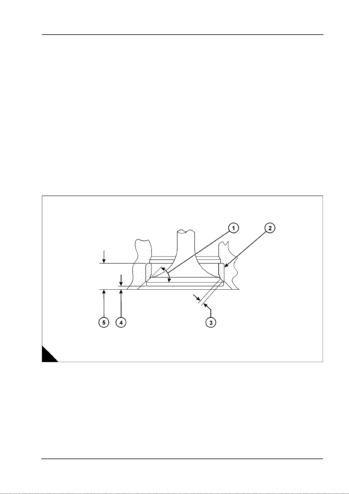
Valve seat inserts
Depth of bore in cylinder head for valve seat insert (A5):
Inlet valve ... ... ... ... ... ... ... ... ... ... ... ... ... ... ... ... ... ... ... ... ... ... ... ... ... ... ... ... ... ... ... ..11,10 / 11,00 mm
Exhaust valve.. ... ... ... ... ... ... ... ... ... ... ... ... ... ... ... ... ... ... ... ... ... ... ... ... ... ... ... ... ... ..11,10 / 11,00 mm
Diameter of valve seat insert (A2):
Inlet valve ... ... ... ... ... ... ... ... ... ... ... ... ... ... ... ... ... ... ... ... ... ... ... ... ... ... ... ... ... ... ..56,119 / 56,094 mm
Exhaust valve.. ... ... ... ... ... ... ... ... ... ... ... ... ... ... ... ... ... ... ... ... ... ... ... ... ... ... ... ... ..56,620 / 56,595 mm
Bore in cylinder head for valve seat insert (A2):
Inlet valve ... ... ... ... ... ... ... ... ... ... ... ... ... ... ... ... ... ... ... ... ... ... ... ... ... ... ... ... ... ... ... ... ... ... ..56 mm H7
Exhaust valve.. ... ... ... ... ... ... ... ... ... ... ... ... ... ... ... ... ... ... ... ... ... ... ... ... ... ... ... ... ... ... ... .56,50 mm H7
Angle of face of valve seat insert (A1):
Inlet valve insert... ... ... ... ... ... ... ... ... ... ... ... ... ... ... ... ... ... ... ... ... ... ... ... ... ... ... ... ... ... ...30°30’ / 30°00’
Exhaust valve insert ... ... ... ... ... ... ... ... ... ... ... ... ... ... ... ... ... ... ... ... ... ... ... ... ... ... ... ... ... 30° 30’ / 30°00’
Valve recess (A4):
Inlet valve (new parts) . ... ... ... ... ... ... ... ... ... ... ... ... ... ... ... ... ... ... ... ... ... ... ... ... ... ... ... ... ... ... ... . Flush
Exhaust valve (new parts)... ... ... ... ... ... ... ... ... ... ... ... ... ... ... ... ... ... ... ... ... ... ... ... ... ... ... ... ... ... . Flush
Inlet valve ... ... ... ... ... ... ... ... ... ... ... ... ... ... ... ... ... ... ... ... ... ... ... ... ... ... ... ... ... ... ... ... Maximum: 1 mm
Exhaust valve.. ... ... ... ... ... ... ... ... ... ... ... ... ... ... ... ... ... ... ... ... ... ... ... ... ... ... ... ... ... ... Maximum: 1 mm
2
A
Workshop Manual, TPD 1511E, issue 1 11
D1366
Page 24
2
Cylinder head
Thickness of cylinder head (new) .. ... ... ... ... ... ... ... ... ... ... ... ... ... ... ... ... ... ... ... ... 140,075 / 139,925 mm
Minimum thickness for a used cylinder head. ... ... ... ... ... ... ... ... ... ... ... ... ... ... ... ... ... ... ... ... 139,773 mm
Flatness of cylinder head: The cylinder head flame face must be flat within a maximum of 0,03 mm (0.001
in) with the rocker box face parallel within 0,076 mm.
Piston and connecting rod
Piston ring gaps measured with the ring fitted in a new liner with a bore size: 160,025 / 160,000 mm
Top piston ring... ... ... ... .. . ... ... ... ... ... ... ... ... ... ... ... ... ... ... ... ... ... ... 0,80 mm, maximum worn 1,05 mm
Intermediate ring (second). ... ... ... ... ... ... ... ... ... ... ... ... ... ... ... ... ... ... 0,60 mm, maximum worn 0,85 mm
Oil control ring ... ... ... ... ... ... ... ... ... ... ... ... ... ... ... ... ... ... ... ... ... ... ... 0,60 mm, maximum worn 0,85 mm
Width of groove for oil control ring in new piston... ... ... ... ... ... ... ... ... ... ... ... ... ... ... ... ... 6,065 / 6,040 mm
Thickness of a new oil con tro l ring. ... ... ... ... ... ... ... ... ... ... ... ... ... ... ... ... .. . ... ... ... ... ... 5,990 / 5,975 mm
Clearance between piston ring groove and new oil control ring ... ... ... ... ... ... ... ... ... ... ... ... ... ... ... ... ... ...
Maximum permissible clearance between piston
ring groove and a used oil control ring... ... ... ... ... ... ... ... ... ... ... ... ... ... ... ... ... ... ... ... ... ... ... ... 0, 254 mm
Piston gudgeon pin bore ... ... ... ... ... ... ... ... ... ... ... ... ... ... ... ... ... ... ... ... ... ... ... ... ... 63. 525 / 63,515 mm
Gudgeon pin diameter ... ... ... ... ... ... ... ... ... ... ... ... ... ... ... ... ... ... ... ... ... ... ... ... ... ... 63,500 / 63,492 mm
Length of gudgeon pin... ... ... ... ... ... ... ... ... ... ... ... ... ... ... ... ... ... ... ... ... ... ... ... ... ... 135,00 / 134,75 mm
Bore in connecting rod for small end bearing ... ... ... ... ... ... ... ... ... ... ... ... ... ... ... ... ... 71,450 / 71,425 mm
Bore of connecting rod small end bearing . ... ... ... ... ... ... ... ... ... ... ... ... ... ... ... ... ... ... 63,576 / 63,551 mm
Bore in connecting rod for big end bearing shells.. ... ... ... ... ... ... ... ... ... ... ... ... ... ... 123,025 / 123,000 mm
Distance between centres of big and small end bearings.. ... ... ... ... ... ... ... ... ... ... ... ... 336,06 / 335,94 mm
Maximum worn clearance small end.. ... ... ... ... ... ... ... ... ... ... ... ... ... ... ... ... ... ... ... ... ... ... ... ... ..0,15 mm
Conrod end float ... ... ... ... ... ... ... ... ... ... .. . ... ... ... ... ... .. . ... ... ... ... ... ... ... ... ... .. . ... ... ... 0,16 / 0,36 mm
4000 Series
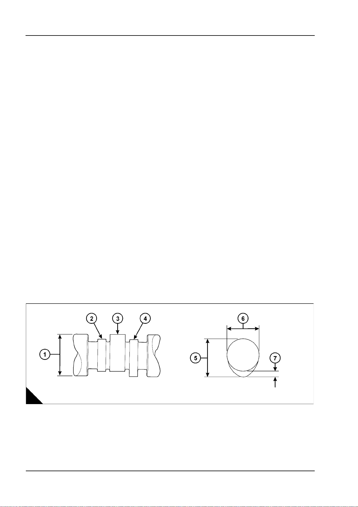
Camshaft and bearings
Diameter of camshaft journal (A3). ... ... ... ... ... ... ... ... ... ... ... ... ... ... ... ... ... ... ... ... ... 91,960 / 91,933 mm
Exhaust cam height (A5) ... ... ... ... ... ... ... ... ... ... ... ... ... ... ... ... ... ... ... ... 78,58 mm, service limit 78,1 mm
Inlet cam height (A5) .. ... ... ... ... ... ... ... ... ... ... ... ... ... ... ... ... ... ... ... ... ... 78,58 mm, service limit 78,1 mm
Injector cam height. ... ... ... ... ... ... ... ... ... ... ... ... ... ... ... ... ... ... ... ... ... ... 78,88 mm, service limit 78,4 mm
Maximum: worn clearance cam journal / bearing .. ... ... ... ... ... ... ... ... ... ... ... ... ... ... ... ... ... ... ... ..0,25 mm
Camshaft end float . ... ... ... ... ... ... ... ... ... ... ... ... ... ... .0,10 / 0,25 mm, maximum: worn clearance 0,30 mm
Cam follower lever assembly:
followers, pivot shaft / arms / shims end float ... ... ... ... ... ... ... ... ... ... ... ... ... ... ... ... ... ... ... 0,50 / 0,25 mm
A
D1365
12 Workshop Manual, TPD 1511E, issue 1
Page 25
4000 Series
2
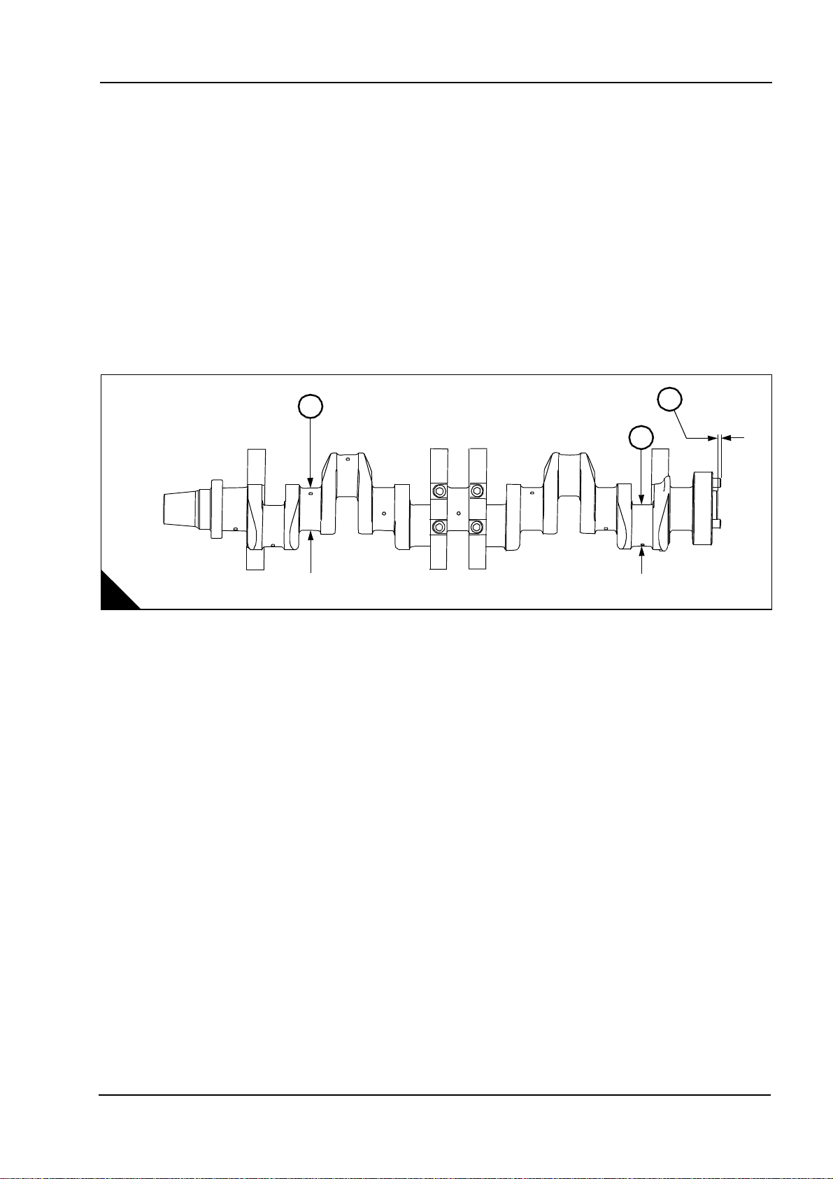
Crankshaft, main bearings and flywheel
Diameter of main bearing journal (A3). ... ... ... ... ... ... ... ... ... ... ... ... ... ... ... ... ... ... ... ..120,59 / 120,57 mm
Undersize bearings by. ... ... ... ... ... ... ... ... ... ... ... ... ... ... ... ... ... ... ... ... ... ... ... ... ... ... ... ... ... ..0,254 mm
Undersize bearings by. ... ... ... ... ... ... ... ... ... ... ... ... ... ... ... ... ... ... ... ... ... ... ... ... ... ... ... ... ... ..0,508 mm
Clearance between a new bearing and the journal. ... ... ... ... ... ... ... ... ... ... ... ... ... ... ... ..0,152 / 0,089 mm
Maximum permissible clearance between the
bearing and journal.. ... ... ... ... ... ... ... ... ... ... ... ... ... ... ... ... ... ... ... ... ... ... ... ... ... ... ... ... ... ... ..0,203 mm
Diameter of main bearing bore ... ... ... ... ... ... ... ... ... ... ... ... ... ... ... ... ... ... ... ... ... ..120,726 / 120,675 mm
Diameter of connecting rod journal (A2).. ... ... ... ... ... ... ... ... ... ... ... ... ... ... ... ... ... ..118 ,013 / 117,993 mm
Undersize bearings by. ... ... ... ... ... ... ... ... ... ... ... ... ... ... ... ... ... ... ... ... ... ... ... ..0,254 mm and 0.508 mm
Clearance between a new bearing and the journal. ... ... ... ... ... ... ... ... ... ... ... ... ... ... ... ..0,127 / 0,073 mm
Maximum permissible clearance between the
bearing and journal.. ... ... ... ... ... ... ... ... ... ... ... ... ... ... ... ... ... ... ... ... ... ... ... ... ... ... ... ... ... ... ..0,203 mm
End-float of crankshaft. ... ... ... ... ... ... ... ... ... ... ... ... ... ... ... ... ... ... ... ... ... ... ... ... ... ... ... ..0,48 / 0,13 mm
Maximum permissible end-float (with used bearings) . ... ... ... ... ... ... ... ... ... ... ... ... ... ... ... ... ... ... 0, 53 mm
Protrusion of dowel (A1).. ... ... ... ... ... ... ... ... ... ... ... ... ... ... ... ... ... ... ... ... ... ... ... ... ... ... ... ... ... ...10 mm
3
A
1
2
D1364
Crankcase and cylinder liners
Distance from top of crankcase to centre of main
bearing bore ... ... ... ... ... ... ... ... ... ... ... ... ... ... ... ... ... ... ... ... ... ... ... ... ... ... ... ... ... ..540,15 / 540,00 mm
Block cylinder bore depth (for liner flange).. ... ... ... ... ... ... ... ... ... ... ... ... ... ... ... ... ... ... .. 15,20 / 15,12 mm
Distance from bottom of crankcase to centre of main
bearing bore ... ... ... ... ... ... ... ... ... ... ... ... ... ... ... ... ... ... ... ... ... ... ... ... ... ... ... ... ..152,425 / 152,375 mm
Bore in new cylinder liner ... ... ... ... ... ... ... ... ... ... ... ... ... ... ... ... ... ... ... ... ... ... ... ..160,025 / 160,000 mm
Thickness of liner flange .. ... ... ... ... ... ... ... ... ... ... ... ... ... ... ... ... ... ... ... ... ... ... ... ... ... ..13,05 / 13,00 mm
Workshop Manual, TPD 1511E, issue 1 13
Page 26

2
Lubricating oil pump
Diameter of shaft ... ... ... ... ... ... ... ... ... ... ... ... ... ... ... ... ... ... ... ... ... ... ... ... ... ... ... ... 41,913 / 41,888 mm
Diameter of bores in bearing bushes for shaft... ... ... ... ... ... ... ... ... ... ... ... ... ... ... ... ... 42, 039 / 41,974 mm
Length of rotors.. ... ... ... ... ... ... ... ... ... ... ... ... ... ... ... ... ... ... ... ... ... ... ... ... ... ... ... ... 50,800 / 50,775 mm
Depth of bores for rotors ... ... ... ... ... ... ... ... ... ... ... ... ... ... ... ... ... ... ... ... ... ... ... ... ... ... 50,76 / 50,72 mm
Joint O.P. body to cover. ... ... ... ... ... ... ... ... ... ... ... ... ... ... ... ... ... ... ... ... ... ... ... ... ... ... ... ... ... ..0,25 mm
Spring:
Spring rate . ... ... ... ... ... ... ... ... ... ... ... ... ... ... ... ... ... ... ... ... ... ... ... ... ... ... ... ... ... ... ... ... ... .1,32 kg/mm
Load at 51 mm length ... ... ... ... ... ... ... ... ... ... ... ... ... ... ... ... ... ... ... ... ... ... ... ... ... ... ... ... ... ... ... ...30 kg
Load under 30 mm comp: to assembly length... ... ... ... ... ... ... ... ... ... ... ... ... ... ... ... ... ... .. . ... ... ... 39,6 kg
Free length . ... ... ... ... ... ... ... ... ... ... ... ... ... ... ... ... ... ... ... ... ... ... ... ... ... ... ... ... ... ... ... ... ... ... ..73,6 mm
Outside diameter ... ... ... ... ... ... ... ... ... ... ... ... ... ... ... ... ... ... ... ... ... ... ... ... ... ... ... ... ... ... ... ... ..24,6 mm
Spring plunger bore ... ... ... ... ... ... ... ... ... ... ... ... ... ... ... ... ... ... ... ... ... ... ... ... ... ... ... ... ... ... ... ..25,4 mm
Coolant pump
Shaft diameter at the position of the coolant seal.. ... ... ... ... ... ... ... ... ... ... ... ... ... ... ... 25,095 / 25,087 mm
Gear train
Idler gear end float. ... ... ... ... ... ... ... ... ... ... ... ... ... ... ... ... ... ... ... ... ... ... ... ... ... ... ... ... ... ... 0,2 / 0,1 mm
Idler gear maximum: worn . ... ... ... ... ... ... ... ... ... ... ... ... ... ... ... ... ... ... ... ... ... ... ... ... ... ... ... ... ..0,25 mm
Backlash:
4000 Series
Idler, camshaft, oil pump gears.. ... ... ... ... ... ... ... ... ... ... ... ... ... ... ... ... ... ... ... ... ... ... ... 0,375 / 0,125 mm
Maximum: worn.. ... ... ... ... ... ... ... ... ... ... ... ... ... ... ... ... ... ... ... ... ... ... ... ... ... ... ... ... ... ... ... ... ... 0,5 mm
Water pump gear in mesh.. ... ... ... ... ... ... ... ... ... ... ... ... ... ... ... ... ... ... ... ... ... ... ... ... ... 0,294 / 0,152 mm
14 Workshop Manual, TPD 1511E, issue 1
Page 27

4000 Series
Torq ue data
2
Description Thread size
Crankcase and crankshaf t
Sump bolts into crankc a se M10 54 40 5,5
Sump bolts into gearcase (al um inium) M10 40 30 4
Main bearing cap bolts See Operation 5-6
Main bearing cap side caps crews M16 n/a n/a n/a
Oil feed block bolts M10 27 20 2,7
Connecting rod bolts See Operation 4-2
Piston cooling jet bolts M10 27 20 2,7
Camshaft
Camshaft gear bolts M12 150 110 15,2
Camshaft thrust plate bolt s M10 50 35 5,1
Idler gear hub bolts M10 50 35 5,1
Engine feet bolts M10 50 35 5,1
Cylinder head
Cylinder head bolts (Fac tory Fitted) 175 + 120°
Cylinder head bolts (Waisted) - head marked ‘W’ M24 720 530 73,4
General
M20 - Grade 8.8 steel bolts to BS3692 M20 400 290 40,7
M16 - Grade 8.8 steel bolts to BS3692 M16 210 150 21,4
M12 - Grade 8.8 steel bolts to BS3692 M12 85 60 8,6
M10 - Grade 12.9 steel bolts to BS3692 M10 70 50 7,1
M10 - Grade 8.8 steel bolts to BS3692 M10 50 35 5,1
M8 - Grade 8.8 steel bolts to BS3692 M8 25 18 2,5
M6 - Grade 8.8 steel bolts to BS3692 M6 10 7 1,0
M6 - Grade 12.9 steel capscrews to BS4168: Part 1 M6 16 12 1,6
M5 - Grade 12.9 steel capscrew to BS4168: Part 1 M5 13 10 1,3
3/8” UNF 40 30 4
5/8” UNF 200 150 20,3
1/2” UNC 90 68 9,1
7/16” UNF 66 50 6,7
5/16” UNF 22 16 2,2
Starte r motors M12 95 70 7,1
Alternator nut M24 75 55 7,6
Taper lockbush M8 20 15 2
Fuel pipes 50 35 5,1
Nm lbf ft kgf m
Torque
130 +
120°
17,8 + 120°
Workshop Manual, TPD 1511E, issue 1 15
Page 28

2
Main build
4000 Series
Description Thread size
Camshaft
Cam follower housing bolts M10 50 35 5,1
Cylinder head
Rocker box bolts-graphite joint M10 70 50 7,1
Exhaust manifol d to head bolts (Durlock) M10 70 50 7,1
Bridge piece adjuster nubs M10 35 25 3,5
Fuel injector clamp capscrews M12 95 70 9,6
Rocker shaft capscrew/nuts M16 240 180 24,9
Rocker adjuster nuts M12 50 35 5,1
Unit-fuel injector rocker adjuster nuts M14 70 50 7,1
Rocke r co v e r - plast ic M10 4 3 0,4
Water pump and oil pump
Water pump to gearcase bolts M10 50 35 5,1
Water header to oil cooler bolts M10 50 35 5,1
Crankcase and crankshaft
Flywheel bolts (Fi nal torque) See Chapter 13, Flywheel and housing
T.V. damper bolts (Fi nal torque) See Chapter 13, Flywheel and housing
Front crankshaft pulley assembly M16 340 250 34,6
Unit-fuel injector control linkage
Capscrews, unit -fuel injector cont rol lever M5 8 6 0,8
Locknut - contr ol linkage M5 8 6 0,8
Exhaust bellows
Bolts / locknu ts ( torque prevailing) M10 58 43
Durlock bolts / loc knuts M10 70 50
Setscrews M10 50 35 5,1
Unit- fuel inject ors
Nuts, fuel injec tor nozzle to nozzle holder M27 205 150 5,9
Capscrews, fuel injector clamp to cylinder head M12 95 70 9,6
Clips and clamps
Hose clips 53,50,5
V-band clamps (Mitsubishi) 9,5 7 0,96
Nm lbf ft kgf m
Torque
16 Workshop Manual, TPD 1511E, issue 1
Page 29

4000 Series
3
Cylinder head assembly 3
General description
Note: In the event of failure, valve or valve seat recession reaching the recommended limit, or when the engine
is being overhauled, service exchange cylinder heads supplied by your Perkins Dealer/Distributor are
recommended. The specialised equipm ent and liquid nitrogen are not generally available
The cast iron cylinder heads are fastened to the crankcase by flange head bolts and hardened washers. The
cylinder head gasket to crankcase consists of a stainless steel flame ring. The individual inlet and exhaust
ports are designed to assist and improve air flow. The ports for the inlet are on the right hand side of the engine
and the ports for the exhaust are on the left hand side of the engine.
The cylinder head assembly has four overhead valves for each cylinder. Each valve is held in place by a single
coil spring, cap and two collets. The cylinder head has valve seat inserts fitted for both the intake and the
exhaust. The intake valve seats are made from high speed steel casting and the exhaust valve seats are made
from Pleuco PL12 MV400 which both can be renewed. The valves move in cast iron ferrite nitro carburised
valve guides which also can be renewed.
The overhead valves are operated by a rocker shaft assembly in the rocker box. The forged steel rocker levers
are operated by forged push rods with hardened ball and sockets ends. The rockers and valve gear are
lubricated by oil from the drillings in the rocker shaft that receives oil flow from the extruded fuel/oil rail. Tappet
adjustment is achieved by adjustment screws and locknuts at the push rod end of each rocker lever.
In a diesel engine there is little carbon deposit and for this reason the number of hours run is no indication of
when to overhaul a cylinder head assembly. The factors which indicate when an overhaul is necessary are
how easily the engine starts and its general performance.
Workshop Manual, TPD 1511E, issue 1 17
Page 30
3
5
4000 Series
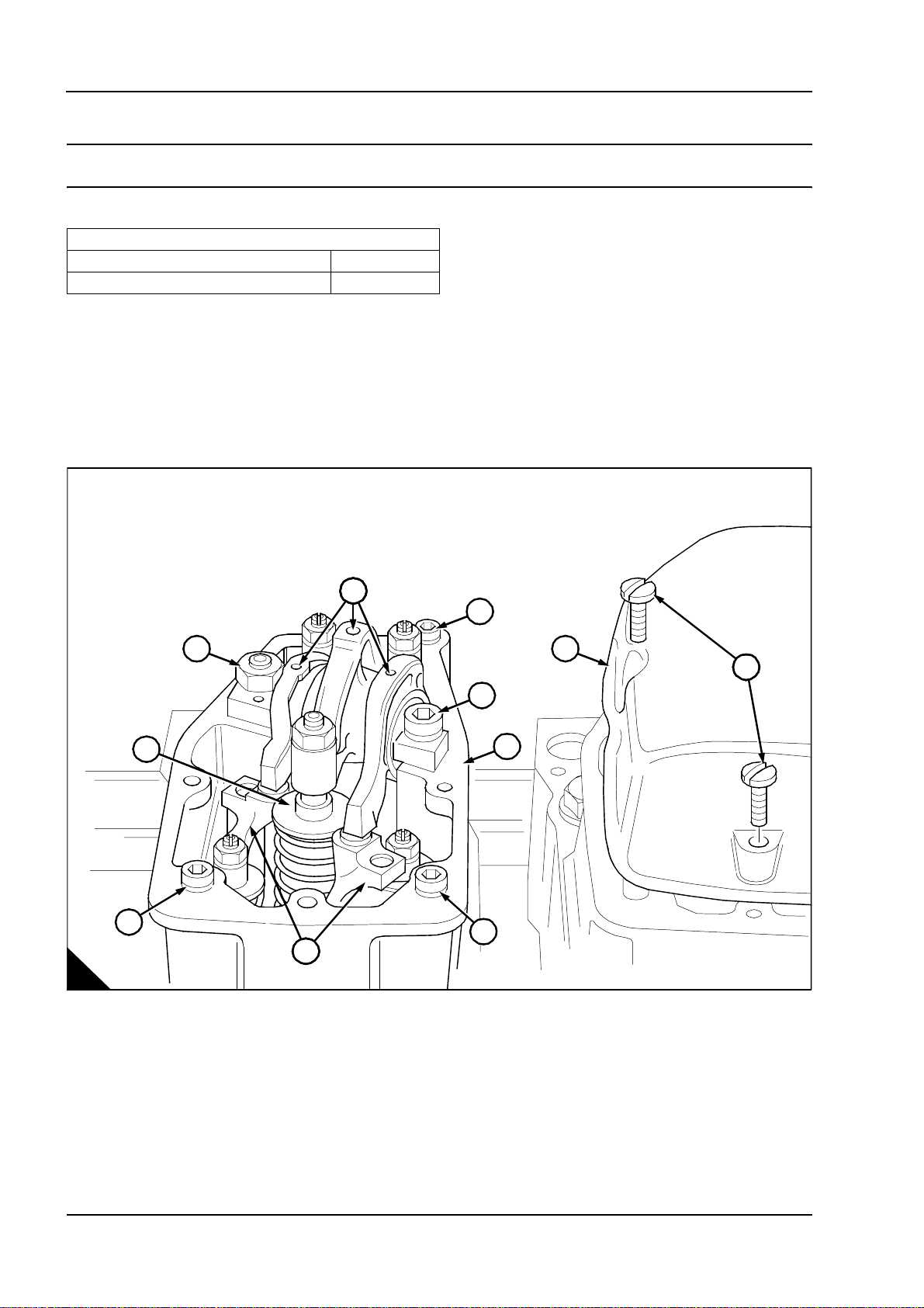
Rocker box and valve gear
To remove and fit the rocker box and valve gear Operation 3-1
Special requirements
Consumable products
Description Part number
POWERPART Hydraulic threadseal 21820121
To remove
1 Remove the retaining screws (A5) and lift off the rocker cover (A4). Remove the rocker cover joint and
discard.
2 Remove the nut (A11) and the Allen screw (A3) then lift off the rocker assembly (A1), the cup pad (A10), the
bridge pieces (A8) and the push rods.
3 Remove the retaining Allen screw (A2, A7, A9) and remove the rocker box (A6).
4 A light blow with a hide mallet may be needed to free the rocker box from its joint.
A
1
2
11
3
10
9
8
6
7
4
5
D135
Continued
18 Workshop Manual, TPD 1511E, issue 1
Page 31

4000 Series
5
3
To fit
Note: If water is found to be leaking from the rocker shaft stud, apply POWERPART Threadlock and nutlock.
1 Fit the rocker box (A6) using a new joint and ‘O’ ring, locating it on the two dowel pegs in the cylinder head
face.
2 Lub ricate the threads of the retaining Allen screw (A2,A7, A9) with clean engine oil then torque to 70 Nm
(50 lbf ft) 7,1 kgf m.
3 Lub ricate all valve gear bearing surfaces with clean engine oil then fit each item to its original position.
4 Lubricate the thread of the nut (A11) and the Allen screw (A3) with clean engine oil then torque to 250 Nm
(180 lbf ft) 25,5 kgf m.
Note: Ensure that the rocker shaft is pulled squarely onto the rocker box.
5 Set bridge piece and valve clearances, refer to the relevant User Handbook, Chapter 4, page 33.
6 Fit a new joint to the rocker cover (A4), tighten the retaining screws (A5) to a torque of
4 Nm (3 lbf ft) 0.4 kgf m.
A
1
2
11
4
5
3
10
9
6
7
8
D135
Workshop Manual, TPD 1511E, issue 1 19
Page 32

3
0
6
4000 Series
Valve gear
To inspect rockers, bridge pieces and rocker shaft Operation 3-2
1 Check the push rods (A13) are straight, the cup end (A15) and the spherical end (A12) smooth surfaced and
concentric.
2 Clean the bore and top surface on the bridge piece.
3 Check the adjuster screws and locknuts (A16) are undamaged.
4 Check the clearance between the bridge pieces (A5) and their guide pillars in the cylinder head. For the
maximum clearance, refer to the Data and dimensions for "Rocker assembly" on page 10.
5 Check the valve contact patch (A6) is not indented or chipped.
Note: A small indent on the bridge piece pressure pad can be removed with an oil stone.
6 Check the bridge piece pressure pad (A7) for indentation.
7 Check the rocker shaft (A11) for wear and the oil galleries (A9) are clear.
15
12
13
16
14
11
1
10
2
9
3
4
8
7
5
6
A
20 Workshop Manual, TPD 1511E, issue 1
D135
0000
Page 33

4000 Series
7
3
To replace the bridge piece pressure pad Operation 3-3
Special requirements
Consumable products
Description Part number
POWERPART
1 Remov e the pressure pad (A2) from the bore of the bridge piece.
Caution: There must be no POWERPART under the pressure pad area (A1).
2 Check the surfaces (A4) on each bridge piece.
3 Apply Loct ite activator ‘T’ to the pressure pad stem and the bridge piece, allow to dry.
4 Apply POWE RPA RT retainer (oil tolerant) to the bridge piece bore (A3).
5 Fit the pressure pad, then stand the assembly upright and allow to cure for two hours.
Retainer (oil tolerant) 21820603
1
A
2
4
3
D135
Workshop Manual, TPD 1511E, issue 1 21
Page 34

3
8
4000 Series
Cylinder head
To remove and fit the cylinder head Operation 3-4
Special requirements
Special tools
Description Part number
Cylinder head lif ting tool T6253/237
To remove
1 Remove the rocker box and the valve gear, see Operation 3-1, then remove the fuel injector, see Operation
11-2 and the brake-back lever.
Note: The cylinder head bolts can only be used twice. Before removal, mark each bolt head with a centre
punch dot (A5). Bolts showing two dots must be replaced.
2 Fit the cylinder head lifting tool (A2) then remove the head bolts in sequence shown (A14, A1, A15, A3). Use
a suitable hoist to remove the cylinder head from the crankcase.
3 Discard the ‘O’ rings (A6, A9, A10, A12), the flame ring (A13) and the push rod tunnel insert and ‘O’ ring
(A4) in the cylinder head, clean the surface of the crankcase.
16
5
4
2
1
15
3
6
14
13
12
8
x
7
9
10
A
22 Workshop Manual, TPD 1511E, issue 1
11
D135
Page 35

4000 Series
8
3
To fit
1 Fit the cylinder head lifting tool (A2). Locate the insert and joint (A4) into the cylinder head combustion face
secure it in position with suitable petroleum jelly.
2 Fit the flame ring (A13) to the liner flange then fit the ‘O’ rings (A6, A9, A10, A12) secure them in position
with petroleum jelly.
3 Use suitable lift equipment in order to lift the cylinder head into position. Ensure that the dowels (A8 and
A11) are aligned. Also ensure that (A7) is in the push rod tunnel. Remove the lifting tool (A2).
4 Using a suitable PBC grease (poly butyl cuprysil) apply one stripe to the bolt thread and coat both sides of
the head bolt washers. Fit the bolts and washers hand tight.
Cylinder head bolt torque sta ges
Stage Torque
1 Hand tight
2 135 Nm
3 270 Nm (200 lbf ft) 27,5 kgf m
4 540 Nm (400 lbf ft) 55,0 kgf m
5 715 Nm (530 lbf ft) 73,9 kgf m
(100 lbf ft) 13,7 kgf m
5 Torque the cylinder head bolts in the stages given, and in the same diagonal sequence (A14, A1, A15, A3).
16
5
4
x
2
1
3
7
6
14
8
9
13
15
12
10
A
11
D135
Workshop Manual, TPD 1511E, issue 1 23
Page 36

3
4000 Series
Valves and springs
To remove and fit the valve and the valve springs Operation 3-5
Special requirements
Special tools
Description Part number
Valve spring compressor T6253/243
Warning! Wear eye protection during this operation.
To remove
1 Carefully turn the cylinder head on its side (A2) and remove the push rod ‘O’ ring and insert (A1).
2 Using the spring compressor (A7), compress a valve spring and remove the split collets (A5) then release
the spring (A6) and retaining collar (A4) then pull the valve (A9) out of the cylinder head.
3 Mark valves for correct assembly and keep all valves together.
A
1
2
9
3
8
7
4
5
6
D1359
Continued
24 Workshop Manual, TPD 1511E, issue 1
Page 37

4000 Series
9
3
To fit
1 Fit the appropriate valve to a universal sucker type tool and apply a medium carborundum paste, evenly
around the valve seat (A1)
2 Fit the valve guides (B3).
3 Push the valve into its guide and use a semi rotary motion lap the valve onto its seat.
4 The sea t of the valve and on the cylinder head must have a grey continuous line of contact.
5 Remov e all traces of the carborundum paste from the cylinder head and valve sea t.
1
A
D1246
6 Lub ricate the valve stem and fit the valve (B8) into the cylinder head.
Caution: Ensure that the valve springs (B6) are compressed squarely or the valve stem can be damaged.
7 Fit the valve spring and retaining collar onto the valve stem, compress the valve spring and fit the split collets
(A6) then slowly release the compressed valve spring, check the collets have seated in the retaining collar.
2
1
9
3
8
7
4
5
6
B
D135
Workshop Manual, TPD 1511E, issue 1 25
Page 38

3
0
4000 Series
To inspect Operation 3-6
1 Visually examine the valve seating face (A2) for pitting or burning. Examine the valve stem (A4) for score
marks or a wear ridge near the collet groove (A5).
2 Check the valve stem dimension (A4), refer to the Data and dimensions for "Valves" on page 10.
3 If the valve is within s ervice li mits but with some pitting on the valve seating face (A2), it can be re-faced at
an angle of 30° (A1).
Caution: If the dimension (A3) is less than 1mm after re-facing the valve should be discarded.
4 Fit a valve into the cylinder head and using a straight edge (A7), check the valve depth. If the depth exceeds
1mm (A6) the valve must be replaced.
5 Support the cylinder head on two blocks of wood (A8). Fit the appropriate valve into the cylinder head, and
hold the valve seat so it protudes 10mm from the surface of the cylinder head. Use an engineer square as a
datum (A10) and check the clearance between the valve and valve guide. If the clearance exceeds 0.5mm
(0,0196 in) the valve guide must be replaced, see Operation 3-8.
6 Check the valve spring free length. If less than 55.6mm (2,188 in), the valve spring must be replaced, see
Operation 3-5.
1
9
8
10
2
4
7
4
5
6
3
A
26 Workshop Manual, TPD 1511E, issue 1
D136
Page 39

4000 Series
4
3
Valves seats
To remove and fit, and reface the valve seats Operation 3-7
Special requirements
Special tools
Description Part number
Valve seat fitting tool T85002/4
Valve seat grinding equipment T6253/240
Warning! Wear eye protection during this operation.
To remove
1 Mac hine down a valve head until it just fits inside a valve seat.
2 Using an electrical welding source, tack weld the valve to the seat in three evenly spaced positions.
3 Allow time for the valve and seat to cool, then using a soft faced hammer, knock the valve and seat out of
the cylinder head.
To fit
1 Check tha t the valve seat bore is free from burrs, and that the valve guide bore is free from carbon.
2 Immerse the valve seat in liquid nitrogen for 2 minutes to get the necessary contraction. This makes the seat
a light tap fit into the cylinder head using the fitting tool (A1).
Caution: The valve seats are made from a very hard material and the valve seat angle can only be cut with
the use of specialist valve grinding equipment (B) and the grinding kit (C) for the stone (B4). Refer to page 10
of data and dimensions for the correct seat angle.
A
1
2
3
1
4
D1242
B
D124
C
D1245
Workshop Manual, TPD 1511E, issue 1 27
Page 40

3
4000 Series
Valves guides
To remove and fit the valve guides Operation 3-8
Special requirements
Special tools
Description Part number Description Part number
Valve guide removal tool T6253/307 Valve guide fitting tool T85090/2
Warning! Wear eye protection during this operation.
Note: When fitting new valve guides the valve seats must be re-cut or re-ground.
To remove
1 Locate the valve guide removal tool into valve guide, using a suitable press push the valve guide out of the
cylinder head from the valve spring side.
To fit
1 Check that the valve bore is free from burrs and carbon.
Caution: Do not use a hammer to locate or to fit the valve guide.
2 Align the valve guide with its bore.
3 Set the fitting tool on top of the valve guide. Using a suitable press, push the valve guide into the cylinder
head until valve guide is 9 mm (0.3543 in) (A) below the face of the cylinder head.
A
9mm
D1243
28 Workshop Manual, TPD 1511E, issue 1
Page 41

4000 Series
7
3
Fuel injector bush
To remove and fit a fuel injector bush Operation 3-9
Special requirements
Special tools
Description Part number Description Part number
Bush insertion tool T85002/2 Bush swaging tool T6253/156
Bush expanding tool lower T8500 2/6 Facing cutter T85002/7
Bush expanding tool uppe r T85002/58 Depth gauge T85002/14B
Warning! Wear eye protection during this operation.
Note: If coolant is found to be leaking from between the cylinder and the fuel injector, or if the fuel injector bush
is damaged, the fuel injector bush must be replaced.
To remove
1 Use a 22 mm (0.8661) drill with a 60 degree angle (A) to drill th e swag ing of the fuel injec to r bush.
2 Use a suitable tool (B) from the combustion side of the cylinder head to remove the remaining fuel injector
bush. Remove the “O” ring and discard (C).
A
C
22 mm
60°
D1236
D1238/2
B
D123
Workshop Manual, TPD 1511E, issue 1 29
Page 42

3
1
To fit
Note: When using the fuel injector bush expander tools, the pressure on the bush is automatically controlled
by the tools as they rotate.
1 Apply a suitable lubricant to the new ‘O’ ring, then fit the ‘O’ ring into the recess in the fuel injector bush
aperture.
2 Slide the fuel injector bush (A3) onto the insertion tool (A2) then fit the locating pin (A4) into the tool and the
fuel injector bush.
3 Carefully locate the fuel injector bush into the cylinder head, ensuring that the ‘O’ ring (A1) is still correctly
positioned.
4 When the fuel injector bush has located in the combustion side of the cylinder head, carefully force the bush
into position.
5 With the fuel injector bush in the correct position, check that the end of the bush (A5) is 1.5mm (0.0590 in)
from the cylinder head face (A6).
4000 Series
2
1
7
3
4
5
6
A
30 Workshop Manual, TPD 1511E, issue 1
D136
Continued
Page 43

4000 Series
2
3
6 Using the expander tools, first expand the lower section bush (combustion side) (B4) then the upper section
bush (valve spring side) (B1).
7 Fit the coning tool (B2) to the combustion side of the bush, then torque the nut to 55 Nm (40 lb/ft)
5,6 kgf m to swage the bush into the chamfer (B3) in the combustion face of the cylinder head.
1
B
3
4
2
D136
Continued
Workshop Manual, TPD 1511E, issue 1 31
Page 44

3
3
8 Check the distance between the fuel injector seating face (C3) and the cylinder head face (C1) with a depth
gauge. The finished dimension (C4) is 122,6 ±0.105 mm (4.827 ± 0.004 in.).
9 If necessary, use the face cutter (C2) to set the dimension correctly.
10 Remove all debris.
1
4000 Series
C
4
3
2
D136
32 Workshop Manual, TPD 1511E, issue 1
Page 45

4000 Series
3
Cylinder head
To inspect and pressure test Operation 3-10
Warning! Wear eye protection during this operation.
1 Remov e the valves and springs, see Ope ration 3-5.
Note: Do not scratch any machined surface on the cylinder head.
2 Clean the carbon deposits from the combus tion face and the ports of the cylinder head.
3 Wa sh the cylinder head with a special solvent which must be used in accordance with the manufacturer's
instructions. Dry the cylinder head using compressed air.
4 Test the cylinder head for leaks, refer to the Data and dimensions for "Cylinder head" on page 12.
5 When the cylinder head is thoroughly clean, check it for cracks. Inspect carefully the areas around the valve
seats and around the hole for the fuel injector.
Workshop Manual, TPD 1511E, issue 1 33
Page 46

3
4000 Series
Manifolds
To remove and fit the induction manifold Operation 3-11
To remove
Note: The induction manifold can be removed as individual sections or as a complete assembly.
1 Remove the digital govenor control unit, see Operation 14-17.
2 Remove the air filter bracket, see Operation 9-5.
3 Loosen the hose clips from the induction manifold pipes. Remove the links and setscrews that secure both
pipes. Remove the hoses from the induction manifold pipes.
4 Remove the inlet manifold to cylinder head setscrews (A1), then remove the inlet manifold. Discard the
joints.
To fit
1 Fit new joints to the induction manifold. Tighten the setscrews to the induction manifold, gradually and evenly
to a torque of 50 Nm (37 lbf ft) 5,1 kgf m.
2 Fit the hoses from the induction manifold pipes, and tighten the hose clips to the radiator pipes and the
induction manifold pipes.
3 Fit the links and setscrews that secure both pipes, and tighten the setscrews to torque of 25 Nm
(18,4 lbf ft) 2.5 kgf m.
4 Fit the air filter bracket, see Operation 9-6
5 Fit the digital govenor control unit, see Operation 14-18.
1
A
34 Workshop Manual, TPD 1511E, issue 1
D1255
Page 47

4000 Series
C
3
To remove and fit the exhaust manifold Operation 3-12
autions:
The exhaust manifolds (A7) and (A8) must be removed as separate items. Damage may be caused to the
expansion bellows (A6) if the exhaust manifolds are removed as an assembly.
Ensure that the turbochargers are supported before the exhaust manifolds are removed.
To remove
1 Remov e the 4 nuts and bolts (A3) and remove the 12 setscrews (A1).
2 Remov e the front section of the exhaust manifold (A8). Discard all the old gaskets.
3 Remov e the 4 nuts and bolts (A4) and the 4 nuts and bolts (A5).
3
1
2
7
8
4
5
6
A
4 Remov e the 12 setscrews (A2) and remove the rear exhaust manifold (A7). Discard all the old gaskets.
5 If necessary remove the rest of the nuts and bolts on the expansion bellows (A6) and remove the expansion
bellows. Discard the old gasket.
6 Ensure that dirt or fluid can not enter the exhaust system.
Workshop Manual, TPD 1511E, issue 1 35
D1331/1
Page 48

3
To fit
1 Ensure that all contact surfaces are clean and dry.
2 Align the new gaskets (A1) to both turbochargers and align the 3 new gaskets for the rear exhaust manifold
(B7) to the cylinder head.
1
A
A
3 Fit loosely the 4 bolts and nuts (B4) and (B5).
4 Fit loosely the 12 setscrews (B2).
D1206/4
4000 Series
3
1
2
7
8
4
5
6
B
Caution: Ensure that the arrow marked on the expansion bellow points towards the turbochargers. The arrow
indicates the direction that the exhaust gas must flow.
5 If removed fit the expansion bellows (B6) complete with a new gasket to the rear exhaust manifold (B7).
Tighten the 4 nuts and bolts to 58 Nm (42.8 lbf ft) 5,9 kgf m.
36 Workshop Manual, TPD 1511E, issue 1
D1331/1
Continued
Page 49

4000 Series
6 Align the front exhaust manifold (B8) to the expansion bellows (B6) and a new gasket. Also align the front
manifold (B8) to the cylinder head and with 3 new gaskets.
7 Fit loosely fit the 12 setscrews (B1) and the 4 bolts and nuts (B3).
8 Tighten the 12 rear setscrews (B2) evenly to a torque of 70 Nm (52 lbf ft) 7,1 kgf m.
9 Tighten the 12 front setscrews (B1) evenly to a torque of 70 Nm (52 lbf ft) 7,1 kgf m.
10 Tighten the nuts and bolts (B4), (B5) and (B3) to a torque of 58 Nm (42.8 lbf ft) 5,9 kgf m.
3
Workshop Manual, TPD 1511E, issue 1 37
Page 50

This page is intentionally blank
Page 51

4000 Series
4
Piston and connecting rod assemblies 4
General description
The pistons are fitted with two compression rings and an oil control ring. The aluminium alloy pistons have a
hard wearing reinforced top ring groove. The high specification tapered top ring, with a cut back piston land,
provides a pressure balance that, along with improved oil removal, ensures low emissions in operation.
The pistons are cooled by the piston cooling jets.
Axial location of the fully floating gudgeon pin is by circlips.
The connecting rods are machined from ‘H’ section forgings. The c onnecting rods have a wedge shaped small
end and bush.
Workshop Manual, TPD 1511E, issue 1 37
Page 52

4
0
4000 Series
Piston and connecting rod
To remove Operation 4-1
Special requirements
Special tools
Description Part number
Engine cranking device SE253
Piston removal and installation tool T6253/212
Warning! Disconnect the batteries and any other power that can start the engine.
Note: The cylinder heads are separate items and can be removed separately.
1 Remove the required cylinder head, see Operation 3-4.
2 To remove the piston cooling jets, see Operation 4-11.
1
1
2
3
A
3 Fit the engine cranking device (A2).
Note: The cranking device (A2) may be fitted ether side of the flywheel housing (A1). To fit the cranking device
remove the inspection cover (A3) or the starter motor.
4 Thoroughly clean the area around the inspection cover (B2). Remove the 2 fasteners and the washers (B1)
from the crankcase. Remove the inspection cover (B2). Also remove the “O” ring (B3).
5 Use the engine cranking device to rotate the crankshaft to allow access to the big end fasteners.
D1145
B
3
2
D113
Continued
38 Workshop Manual, TPD 1511E, issue 1
Page 53

4000 Series
1
0
6 Remov e the carbon build up from around the top of the cylinder liner bore (C1).
Caution: Do not damage the cylinder liner when the carbon is removed.
1
4
1
2
C
D1146
D
D1131/
7 Remov e the fasteners (D1) and remove the bearing cap (D2).
8 Rotate the crankshaft until the relevant connecting rod is just after TDC.
Note: Make sure that the bearing shell is still in the connecting rod.
9 Fit the removal tool (E1) into the valve cut-out in the top of the piston.
1
1
E
D1133
F
D114
10 Carefully remove the piston and connecting rod, complete with the bearing shell.
11 Remove the tool (E1) from the piston.
Caution: Do not etch or centre punch the connecting rod assembly to identify the cylinder bore it was removed
from.
12 Check that the connecting rod and cap have the correct identification marks (F1). Keep the relevant
connecting rod, cap and bearing shells together. Also mark the connecting rod assembly to identify the cylinder
bore it was removed from.
Continued
Workshop Manual, TPD 1511E, issue 1 39
Page 54

4
13 Mark the big end fasteners to show the number of times that it has been used (G).
4000 Series
1
3
G
(G1) First time removed.
(G2) Second time removed.
(G3) Third time removed.
Caution: At the fourth time of removal, the fastener (G3) must be renewed.
2
D1132
40 Workshop Manual, TPD 1511E, issue 1
Page 55

4000 Series
1
4
To fit Operation 4-2
Special requirements
Special tools
Description Part number
Piston ring compressi on tool T6253/139
Piston removal and installation tool T6253/212
A 30° indicator socket SE671K
Caution: If the original piston and rings are not renewed they must be fitted in the original cylinder.
Note: If a new connecting rod is to be fitted, the weight of the new connecting rod must be within the range of
of the original connecting rod. The weight of the connecting rod is marked on the rod.
1 Ensure that the piston, cylinder bore, crank pin and the big end of the connecting rod are clean and free from
damage. Lubricate the piston and the cylinder liner with clean engine lubricating oil.
2 Check that the bearing shells are fitted correctly in the connecting rod and cap, see Operation 4-6. Lubricate
the bearing shells with clean engine lubricating oil.
3 Fit the piston installation
4 Check that the piston cut out (B1) is aligned correctly to the long side of the connecting rod (B3).
Caution: Do not fit the piston cooling jet until the piston assembly is fitted.
tool (A1) into the valve cut-out in the top of the piston.
5 Check that the piston ring gaps are 120° apart. Fit the ring compression tool to the piston (A2). Check that
the cut out in the piston (B1) is aligned to the piston cooling jet (B2), when the piston cooling jet is fitted in the
engine. Fit the assembly into the correct cylinder.
6 Push the piston and connecting rod assembly through the piston ring compression tool (A2) and down the
cylinder bore, onto the crank pin.
1
2
1
2
3
A
D1139
B
D1137/
7 Remov e the piston ring compression tool (A2).
Continued
Workshop Manual, TPD 1511E, issue 1 41
Page 56

4
0
8 Lubricate the threads and the head of the big end fasteners with clean engine oil.
9 Check the identification marks on the cap (D1) are correct for the connecting rod and the cylinder. Fit the
cap and fasteners and ensure that the marks (D1) are on the same side.
10 Fit the bolts, hand tight whilst checking the end cap has pulled fully up to the connecting rod.
11 Torque the connecting rod bolts to 82 lb.ft (110 Nm)
Note: To complete the operation a further 60° tightening is required but due to a restricted access this is
carried out in two 30° steps.To perform this procedure two people are required.
12 Locate the socket indicator on the big end bolt and apply light pressure to the wrench (C1).
13 Set the leading edge of the indicator (C2) on the centre line of the big end bolt (C3).
14 Tighten the big end bolt until the trailing edge of the indictor (C4) is in line with the centre line of the big end
bolt (C3).
15 Remove the socket indicator from the big end bolt head and turn it back one serration of the big end
bolt.This will bring the leading edge of the indictor (C2) again in line with the centre line of the big end bolt.
16 Tighten the big end bolt until the trailing edge of the indicator is again in line with the centre line of the big
end bolt completing the required 60° angle.
4000 Series
4 30
C
2
3
3
1
1
D1350
1
2
D
D114
E
17 Fit the “O” ring (E3) into the recess in the inspection hole and fit the inspection cover (E2). Fit the washers
and the fasteners (E1). Torque the fasteners to 50 Nm 37 lbf ft
18 Fit the piston cooling jet or jets, see Operation 4-12.
19 Fit the required cylinder head or heads, see Operation 3-4.
42 Workshop Manual, TPD 1511E, issue 1
D1130
Page 57

4000 Series
4
Piston r ings
To remove Operation 4-3
Special requirements
Special tools
Description Part number
Piston ring tool T6253/256
Note: The pistons are fitted with two compression rings and an oil control ring. All the piston rings are above
the gudgeon pin. To ensure that the correct type of piston ring is obtained always use the engine identification
number to order new parts.
Caution: Only expand the ring gaps enough to ensure that the ends of the rings do not damage the piston
when the ring is removed.
1 Remov e the piston rings with the piston ring tool (A). Keep the rings with their relevant piston.
2 Identif y each ring as they are removed.
A
D1135
Workshop Manual, TPD 1511E, issue 1 43
Page 58

4
C
4000 Series
To fit Operation 4-4
Special requirements
Special tools
Description Part number
Piston ring tool T6253/256
autions:
Only expand the ring gaps enough to ensure that the ends of the rings do not damage the piston when the
ring is put into position.
If the old piston rings are to be fitted, they must be fitted into the original cylinder bore. Care must be taken
to fit the rings the correct way up.
Note: Us e the piston ring tool to fit the piston rings.
1 Fit the spring of the oil control ring in the bottom groove with the latch pin (A1) inside both ends of the spring.
Fit the oil control ring over the spring (B3). Ensure that the ring gap is at 180° to the latch pin.
Note: The two compression rings may have a paint mark or the word “TOP”. The ring must be fitted to face
the top of the piston.
2 Fit the stepped ring (B2) into the second groove, with the word "TOP" towards the top of the piston.
3 Fit the tapered, top ring (B1) with the word 'TOP' towards the top of the piston.
4 Ensure that the ring gaps are 120° apart.
A
1
2
3
1
D1147
B
JC
D1148
44 Workshop Manual, TPD 1511E, issue 1
Page 59

4000 Series
N
4
Piston and connecting rod assembly
To dismantle Operation 4-5
Special requirements
Special tools
Description Part number
Circlip pliers T6253/238
Caution: Make a temporary mark on the piston. Do not scratch, etch or stamp the piston surface.
1 Put a temporary mark on the piston to indicate the cylinder number the piston was removed from.
2 Remov e the circlips (A2) and (A3) that retain the gudgeon pin (A4). Discard the old circlips.
3 Push the gudg eon pin out by hand. If the gudgeon pin is tight to move, heat the piston to
40/50 °C (100/120 °F) for easy removal of the gudgeon pin.
4 Remov e the bearing shells from the connect ing rod and the bearing cap.
5 Inspec t the piston, see Operation 4-7 and connecting ro d assembly, see Operation 4-8.
To assemble Operation 4-6
1 Clean the bore of the small end bush and lubricate it with clean engine lubricating oil.
2 Fit a new circlip (A2) in the circlip groove of one of the gudgeon pin bosses. Ensure that it fits correctly in
the groove.
3 With the piston upside down, put the connect ing rod in position. Align the long side of the connecting rod
(A1) to the cut out in the piston (A5).
1
5
2
4
3
A
otes:
If the original piston is used, ensure that it is assembled to the correct connecting rod and is used in the
original cylinder.
If a new connecting rod is fitted, ensure that it is of the correct weight grade.
4 Lubricate the gudgeon pin bosses with clean engine lubricating oil and push in the gudgeon pin (A4) towards
the circlip. If the gudgeon pin is a tight fit in the piston, heat the piston to 40/50 °C (100/120 °F) before the
gudgeon pin is fitted.
Note: The gudgeon pin is a fully floating type.
D1149
5 Fit a new circlip (A3) in the other groove in the gudgeon pin boss. Ensure that it fits correctly in the groove.
Continued
Workshop Manual, TPD 1511E, issue 1 45
Page 60

4
4000 Series
1
B
6 Clean the bearing face of the connecting rod and the bearing cap. Install the location tag of the bearing shell
(B1) into the recess in the connecting rod and fit together.
7 Install the location tag of the bearing shell into the recess in the bearing cap and fit together.
D1138
46 Workshop Manual, TPD 1511E, issue 1
Page 61

4000 Series
4
Piston and piston rings
To inspect Operation 4-7
1 Check the piston for wear, other damage, and remove all debris in and around the oil cooling gallery. Renew
as necessary.
2 Remove the piston rings, see Operation 4-3 and clean the piston ring grooves and the piston rings.
3 Fit new piston rings in the grooves and check for wear of the grooves with feeler gauges (A). Compare the
piston ring clearance in the groove to that given for new components, refer to the Data and dimensions for
"Piston and connecting rod" on page 12, and renew the piston and rings, if necessary.
Note: The pistons have a tapered top groove and the piston ring is wedged shaped. The top piston ring
clearance cannot be checked by this method.
4 Clean all carbon from the top of the cylinder liners. Fit each piston ring in the top part of the cylinder liner
and measure the ring gap with feeler gauges (B). The coil spring must be removed from the oil control ring
when the gap of this piston ring is measured. For piston ring gaps on new components, refer to the Data and
dimensions for "Piston and connecting rod" on page 12.
5 Fit the piston rings, see Operation 4-4.
A
D1150
B
D1151
Workshop Manual, TPD 1511E, issue 1 47
Page 62

4
4000 Series
Connecting rod
To inspect Operation 4-8
1 Check the small end bush for wear or for other damage and renew it, if necessary.
2 Check the connecting rod for distortion (A). See "P iston and conn ecting rod" on page 12 to identify the
correct mandrel sizes.
Note: The large and small end bores in the connecting rod (A1) must be square and parallel with each other
within the limits of ± 0,0508 mm (0.002 in) each side of the connecting rod axis on a test mandrel.
3 Check the fit of the gudgeon pin in the small end bush and check the gudgeon pin for wear, see "Piston and
connecting rod" on page 12.
1X
A
G0009
48 Workshop Manual, TPD 1511E, issue 1
Page 63

4000 Series
4
Small end bush
To inspect Operation 4-9
Check that the small end bush is not damaged and is in tolerance, see "Piston and connecting rod" on page
12. Renew if necessary.
To remove and fit Operation 4-10
Special requirements
Special tools
Description Part number
Small end bush extractor and insertion tool T6253/159
The special tool (A) is design to remove and fit the small end bush. The tool as angled side that help keeps the
bush aligned.
Caution: The bush of the connecting rod must be aligned to the parent bore and when fitted the bush must
not protrude from the parent bore.
A
D1152
Workshop Manual, TPD 1511E, issue 1 49
Page 64

4
1
4000 Series
Piston cooling jets
To remove Operation 4-11
Caution: Before the pist on cooling jet is r emoved from the crankcase, ensure that the piston is at TDC for t his
particular cylinder.
1 Thoroughly clean the area around the piston cooling jet (A1). Remove the setscrew and the clamp (A2) from
the crankcase.
2 Rotate the cooling jet (B1) 90° to the right (B2) and remove the cooling jet from the crankcase.
1
A
3 Remove the plug (C2) and discard both ‘O’ ring (C1) and (C3).
4 Clean the cooling jet and check for damage. Renew the cooling jet if necessary.
1
2
D1141/1
B
1
2
D1143/
3
C
50 Workshop Manual, TPD 1511E, issue 1
2
D1142/1
Page 65

4000 Series
C
1
2
4
To fit Operation 4-12
Special requirements
Special tools
Description Part number
Drift
autions:
Before the piston cooling jet is fitted into the engine, ensure that the piston is at TDC.
The piston cooling jet must be renewed if it is found to be damaged. Failure to do so will damage the engine.
1 Fit a new ‘O’ ring (A1) to the cooling jet and fit a new ‘O’ ring (A3) to the plug (A2).
2 Lub ricate the cooling jet and the cooling jet hole with clean engine lubricating oil.
3 Hold the cooling jet in position (B2). Push the cooling jet into the crankcase.
T9142/21
1
1
2
3
A
D1142/1
B
4 Rotate the cooling jet 90° to the left and align the cooling jet to the setscrew hole (B1).
5 Loosely fit the setscrew (C1). Hold the drift (C2) on the end of the cooling jet and insert fully.
1
2
2
D1143/
1
2
C
D1368
D
D1141/
6 Remov e the setscrew (C1). Lubricate the ‘O’ ring and plug (D2) with clean engine lubricating oil and push
the plug into the cooling jet body.
7 Align the clamp and fit the setscrew (D1). Tighten the setscrew to 50 Nm. 37 lbf ft 5 kgf m.
Workshop Manual, TPD 1511E, issue 1 51
Page 66

This page is intentionally blank
Page 67

4000 Series
5
Crankshaft assembly 5
General description
The crankshaft is forged from chromium molybdenum steel and has seven main journals. There is a large
flange at the rear of the crankshaft to which the flywheel is fitted.
o
End-float and thrust movements are controlled by two 180
crankcase be aring.
All of the main bearings have steel backs with an aluminium/tin bearing material. The main bearing caps are
made of spheroidal graphite iron.
The front and the rear oil seals are made from two materials. A outer metal cage and a inner synthetic material.
The front seal is fitted in the oil seal housing. The housing assembly is fitted to the gear case. The rear seal is
a fitted part of the flywheel housing, which is fitted to the crankcase.
These engines have a viscous damper which is fastened to the crank adaptor. The damper is designed for the
suppression of torsional vibrations in the engine crankshaft.
thrust washers on both sides of the rear main
Workshop Manual, TPD 1511E, issue 1 53
Page 68

5
4000 Series
Crankshaft pulley and adaptor
To remove Operation 5-1
Warning! Always use lift equipment of the approved type and of the correct capacity to lift heavy engine
components. Never work alone when you operate lift equipment.
1 Remove the radiator, see Operation 12-21.
2 Remove the fan belts, see Operation 12-14.
3 Remove the 2 fasteners (A3) and fit 2 suitable studs. Remove the other 2 fasteners and remove the pulley
(A4) from the pulley adaptor (A2). Remove the two studs.
4 Remove the 2 fasteners (A1) and fit 2 suitable studs. Remove the other 6 fasteners and remove the pulley
adaptor (A2). Remove the two studs.
1
2
3
A
4
D1153
54 Workshop Manual, TPD 1511E, issue 1
Page 69

4000 Series
1
5
To fit Operation 5-2
1 Check tha t all the components are clean and free from damage.
2 Fit 2 suitable studs into the damper adaptor (A1) and fit the pulley adaptor (A2).
3 Loo sely fit the fasteners (B1) and remove the studs and loosely fit the remainder.
1
2
A
D1154
B
4 Tighten the pulley adaptor fasteners (B1) to a torque of 340 Nm (250.7 lbf ft) 34,6 kgf m.
5 Fit 2 suitable studs into the pulley adaptor (C1) and fit the pulley (C2).
6 Loosely fit the fasteners (D1) and remove the studs and loosely fit the remainder.
7 Tighten the pulley fasteners (D1) to a torque of 85 Nm (62 lbf ft) 8,6 kgf m.
2
1
1
D1155
1
C
D1156
D
D1153/
8 Fit the fan belts, see Operation 12-14.
9 Fit the radiator, see Operation 12-22.
Workshop Manual, TPD 1511E, issue 1 55
Page 70

5
4000 Series
Crankshaft vibration damper assembly
To remove Operation 5-3
Special requirements
Special tools
Description Part number
Puller T6253/209
Warning! Always use lift equipment of the approved type and of the correct capacity to lift heavy engine
components. Never work alone when you operate lift equipment.
1 Remove the mounting bracket for the fan belt adjuster see Operation 12-13.
2 Remove the crankshaft pulley and adaptor, see Operation 5-1.
Note: Us e suitable lift equipment in order to remove the damper assembly.
3 Remove the fasteners (A3) and the plate (A4). Use the special puller remove the damper assembly.
4 Remove the fasteners (A1) and remove the damper adaptor (A5) from the damper (A2).
A
1
2
3
4
5
D1157
56 Workshop Manual, TPD 1511E, issue 1
Page 71

4000 Series
5
To fit Operation 5-4
Warning! Always use lift equipment of the approved type and of the correct capacity to lift heavy engine
components. Never work alone when you operate lift equipment.
1 Check that all parts are clean and free from damage. Align the damper (A1) to the damper adaptor (A2) and
loosely fit the 6 fasteners (A3).
2 Tighten the fasteners to the following procedure and sequence in the table below and in graphic (A).
Stage Torque
1 Hand ti ghten
2 160 Nm (118 lbf ft)
1
3
1
5
1
2
3
6
4
2
2
A
D1158
B
D1157/1
Note: Use suitable lift equipment in order to lift the assembly into position.
3 Fit the retaining plate (B2) and the 3 fasteners (B1). Torque the fasteners to 340 Nm (250 lbf ft) 34,6 kgf m.
Workshop Manual, TPD 1511E, issue 1 57
Page 72

5
4000 Series
Crankshaft
To remove Operation 5-5
Warning! Always use lift equipment of the approved type and of the correct capacity to lift heavy engine
components. Never work alone when you operate lift equipment.
Caution: To remove the crankshaft is a major overhaul. The engine must be rotated to allow access to the
crankshaft.
1 Remove the cylinder heads, see Operation 3-4.
2 Remove piston and connecting rods, see Operation 4-1.
3 Remove the flywheel housing, see Operation 13-3.
4 Remove the gear case, see Operation 6-1.
5 Remove the crankshaft idler gear and the camshaft gear, see Operation 6-7 and Operation 6-5.
Note: Chec k tha t the bearing caps are marked correctly.
6 Remove the main bearing setscrews and washers (A1). Remove the main bearing caps (A2) from the
engine. Each setscrew must be marked to show the number of times that it has been used.
1
2
A
7 Remove the two thrust washers (A4) from both sides of the rear main bearing.
Note: Us e suitable lift equipment (A3) and carefully remove the crankshaft from the crankcase .
8 Remove the main bearing shells from the crank case.
9 Clean all the crankshaft components and check for wear, see "Crankshaft, main bearings and flywheel" on
page 13.
3
4
D1159
58 Workshop Manual, TPD 1511E, issue 1
Page 73

4000 Series
6
5
To fit Operation 5-6
Caution: Do not use a main bearing setscrew that has 3 marks on the head of the setscrew.
1 Ensure that all internal lubricating oil passages are clean and free from restriction. Ensure that the crankshaft
journals are clean.
2 Clean the main bearing housings and fit new bearing shells. Ensure the bearing shell location tags are fitted
correctly in their recesses (A1). Lubricate the bearings with clean engine lubricating oil.
3 Use suitable lift equipment to put the crankshaft above the crank case bearing journals and carefully lower
the crankshaft onto the bearing shells.
4 Clean and lubricate the two halves of the thrust washers (B1) and slide them into their recesses on both
sides of the bearing housing. Ensure that the slotted sides of the thrust washers are fitted away from each
other.
1
1
A
D1160
B
D132
5 Clean the bearing caps (C2). Fit the bearing shells to the caps with the location tags fitted correctly in their
recesses. Lubricate the bearings with clean engine lubricating oil.
6 The identification number stamped on the bearing caps must be the same as the number stamped on the
bottom face of the crank case. Fit the bearing caps (C2), lubricate the main bearing setscrews and washers
(C1) with clean lubricating engine oil. Fit the setscrews (C1).
3
4
D1159/1
C
1
2
Continued
Workshop Manual, TPD 1511E, issue 1 59
Page 74

5
7 Tighten the main bearing setscrews in the sequence give in (D). Tighten the main bearing setscrews to
torque given in table 1. At each stage check that the crankshaft will rotate freely.
531246
7
4000 Series
D
Table 1
Stage Torque
1 Tighten by hand
2 135 Nm (100
3 270 Nm (200 lbf ft)
4 540 Nm (389 lbf ft)
5 783 Nm (577 lbf ft)
8 Check the crankshaft end float, see Operation 5-7.
9 Rotate the crankshaft in order to align the timing marks.
10 Fit the crankshaft idler gear and camshaft gear, see Operation 6-8 and Operation 6-6.
11 Fit the gear case, see Operation 6-2.
12 Fit the flywheel housing, see Operation 13-1.
13 Fit piston and connecting rods, see Operation 4-2.
14 Fit the cylinder heads, see Operation 3-4.
15 Fill the engine with coolant and lubrication oil and prime the fuel system. Refer to the relevant Users
Handbook.
lbf ft)
D1161
60 Workshop Manual, TPD 1511E, issue 1
Page 75

4000 Series
5
To check the crankshaft end float Operation 5-7
The axial movement of the crankshaft is controlled by thrust washers fitted to both sides of the rear main
bearing.
Force the crankshaft towards the front of the engine and back to the rear of the engine. Check the end-float
with a dial gauge (A1).
To check the tolerance for the crankshaft, refer to "Crankshaft, main bearings and flywheel" on page 13
1
A
D1162
Workshop Manual, TPD 1511E, issue 1 61
Page 76

This page is intentionally blank
Page 77

4000 Series
6
Gearcase and drive assembly 6
General description
The gear case is made of aluminium, the gears and the camshaft are made of case hardened steel. The gears
are of a helical design.
The back plate is made of steel and the gear case is mounted on the back plate.
The drive from the crankshaft gear (A4) is passed through an idler gear (A2) to the oil pump gear (A5). The
water pump transmits the drive through a shaft in order to drive the alternator. The oil pump is mounted on the
rear of the back plate.
The idler gear also transmits the power to the coolant pump gear (A1). The coolant pump is mounted on the
front of the gear case.
The camshaft gear (A3) is driven by the crankshaft gear. The camshaft rotates at half crankshaft speed.
A
2
1
5
3
4
D1369
Workshop Manual, TPD 1511E, issue 1 63
Page 78

6
4000 Series
Gearcase
To remove Operation 6-1
1 Drain the engine coolant, Refer to the relevant Users Handbook.
2 Remove the fan drive, see Operation 12-15.
3 Remove the vibration damper, see Operation 5-3.
4 Remove the coolant pump, see Operation 12-6.
5 Remove the stop solenoid, see Operation 14-12.
6 Remove stop lever.
7 Remove the engine breather, see Operation 9-11.
8 Remove the thermostat housing, see Operation 12-5.
9 Remove all the setscrew (A1) that hold the sump to the gear case.
10 Loosen the suction pipe from the oil pump. Loosen all other sump setscrew and allow the sump to move
down onto the loosened setscrews.
2
1
1
A
11 Remove the fasteners (B1) that hold the gear case (B4) to the back plate (B2).
Note: The gear case is dowelled to the back plate.
12 Remove the gear case from the back plate.
13 Remove the joint (B3).
D1370
B
3
4
D1371
64 Workshop Manual, TPD 1511E, issue 1
Page 79

4000 Series
6
To fit Operation 6-2
1 Ensure that the back plate, gears and gear case are clean and free from damage.
2 Fit a new joint (A3) on to the back plate (A2).
2
1
A
Note: In order to help seal the gear case to the sump face, apply a suitable sealant across the sump joint on
both sides of the sump (B1).
3 Align the gear case (A4) to dowels and fit the gear case on to the back plate (A2).
4 Fit the fasteners (A1) and tighten by hand.
5 Fit the setscrews (C1) and tighten by hand.
6 Tighten the fastene rs (A1) evenly to 50 Nm (36.8 lbf ft) 5 kgf m.
7 Tighten the sump setscrews (C1) to 40 Nm (30 lbf ft) 4 kgf m. Tighten the other sump setscrews to 50 Nm
(36.8 lbf ft) 5 kgf m.
3
1
4
D1371
B
B
D1372
1
C
8 Tighten the oil suction pipe from the sump to the oil pump to the following torque 50 Nm 936.8 lbf ft) 5 kgf m0.
9 Fit the thermosta t housing, see Operation 12-5.
10 Fit the engine breather, see Operation 9-12.
11 Fit the coolant pump, see Operation 12-7.
12 Fit the stop solenoid, see Operation 14-13.
13 Fit stop lever.
14 Fit the alternator, see Operation 14-6.
15 Fit the fan drive, see Operation 12-15.
16 Fit the crankshaft vibration damper assembly, see Operation 5-4.
17 Fill the engine with clean lubric at ion oil, Refer to the relevant Users Handbook .
18 Fill the engine coola nt, R efer to the relevant Users Handbook.
Workshop Manual, TPD 1511E, issue 1 65
D1370
Page 80

6
4000 Series
Front oil seal
To remove Operation 6-3
Caution: Care must be taken not to damage the oil seal housing when the oil seal is removed.
1 Remove the crankshaft vibration damper, see Operation 5-3.
2 Remove the nuts from the housing and remove from the gearcase.
3 Use a suitable tool in order to remove the oil seal from the housing.
4 Discard the oil seal from the housing.
5 Ensure that all of the seal is removed from the housing and gearcase.
To fit Operation 6-4
Special requirements
Special tools
Description Part number
Carrier aligment tool T6253/354
1 Inspect the housing and the gearcase for damage.
2 Fit a new joint over the studs and into the gearcase.
3 Fit the housing onto the studs and put the nuts back on the housing. Do not tighten the nuts.
4 Use the alignment tool. Place the alignment tool over the crankshaft and push inwards to locate the housing.
5 Ensure that the alignment tool is inserted fully into the housing.
6 Tighten the nuts on the housing.
2
1
A
7 Remove the alignment tool and fit oil seal locator (A3). Then slide the oil seal along the locator, seat it
squarely in the housing. Fit the outer sleeve (A2) on (A 3) and tighten the nut (A1) until the outer sleeve is f ully
inserted.
Note: E ns ure that the lip side of the seal is towards the oil seal housing.
8 Fit the crankshaft vibration damper, see Operation 5-4.
66 Workshop Manual, TPD 1511E, issue 1
3
D1218
Page 81

4000 Series
6
Camshaft gear
To remove Operation 6-5
Note: The camshaft end float should be checked before the gear is removed, to allow the thrust plate to be
fitted correctly. To check the camshaft end float value, refer to "Camshaft and bearings" on page 12.
1 Remove the gear case, see Operation 6-1.
2 Ensure that the timing marks (A3) on the camshaft gear and the crankshaft gear are aligned.
3 Remove the setscrews (A2) and remove the camshaft gear (A1).
1
2
A
3
D1373
Workshop Manual, TPD 1511E, issue 1 67
Page 82

6
9
4000 Series
To fit Operation 6-6
1 Ensure that the all the components are clean and free from damage.
2 Align the dowel (A2) in the camshaft to the camshaft gear (A1) and align the timing marks (A4) on both gears.
3 Check the camshaft end float value, reference "Camshaft and bearings" on page 12.
4 Fit the gear (A1) onto the camshaft.
5 Fit the setscrews (A3) .
6 Tighten the setscrews to 150 Nm (110 lbf ft) 15,2 kgf m.
7 Use a dial gauge or feeler gauge (B1) to check the camshaft gear back lash.
8 Use a dial gauge (C1) to check the camshaft end float.
2
1
3
1
A
C
4
D1373
1
D1208
B
D121
68 Workshop Manual, TPD 1511E, issue 1
Page 83

4000 Series
6
Idler gear
To remove Operation 6-7
1 Remov e the 2 setscrews (A1) and remove the plate (A2).
2 Remov e the gear (A3) and the hub (A4), from the back plate.
3
2
1
4
A
D1374
Workshop Manual, TPD 1511E, issue 1 69
Page 84

6
2
4000 Series
To fit Operation 6-8
1 Ensure that all the components are clean and free from damage. Check that the oil holes are free from
debris.
2 Lubricate the bush in the gear (A3) with clean Lubricating engine oil.
3
A
2
1
4
D1374
1
B
1
D121
C
3 Align the hub (A4) to the back plate and fit.
4 Fit the gear (A3) onto the hub (A4).
5 Align the plate (A2) to the hub and fit the setscrews (A1).
6 Tighten the setscrews to a torque of 50 Nm (36,8 lbf ft) 5 kgf m.
7 Check the end float (B1) and check the back lash (C1) see "Gear train" on page 14.
D1219
70 Workshop Manual, TPD 1511E, issue 1
Page 85

4000 Series
6
To check the hub and renew the idler gear bush Operation 6-9
1 Clean the hub (A1) and check for wear, see "Gear train" on page 14
2 Use a suitable tool in order to press out the old bush (A2).
1
A
3 Ensure that the gear and new bush are clean and free from damage.
4 Align the new bush to the gear.
5 Use a suitable tool in order to press in the new bush.
2
D1213
Workshop Manual, TPD 1511E, issue 1 71
Page 86

6
4000 Series
Cam followers
To remove and fit Operation 6-10
1 Remove the rockers, see Operation 3-1.
2 Remove the air pipe from the charge cooler to the turbocharger, see Operation 9-9.
3 Remove the 4 setscrews (A1).
1
2
A
4 Remove the cam follower assembly (A2) and the joint. Identify each assembly.
5 Remove all the cam follower assemblies from the crank case.
6 Clean and check each cam follower assembly, see Operation 6-11.
7 Lubricate the assembly with clean lubricating engine oil.
8 Fit a new joint to the assembly and fit the assembly into the crank case.
9 Fit the 4 setscrews (A1) and torque the setscrews to 50 Nm (36,8 lbf ft) 5 kgf m.
10 Fit the rockers, see Operation 3-1.
11 Fit the air pipe from the charge cooler, see Operation 12-22.
D1375
72 Workshop Manual, TPD 1511E, issue 1
Page 87

4000 Series
6
To check Operation 6-11
A visual inspection is required of the load bearing surface. If excessive wear or play is present the assembly
must be repaired or renewed.
Note: A service exchange unit can be supplied if the cam follower is out of tolerance.
1 Mark the position of each cam follower arm.
Exhaust arm Fuel arm Inlet arm
(A8) (A7) (A6)
2 Remove the allen screw (A2) and remove the oil thrower.
3 Remove the allen screws (A1) and remove the shaft (A5).
Note: The arms are shimmed in order to allow end float of 0,5 to 0,25 mm (0.019 in to 0.0098 in).
4 Mark the shims in order to help assemble the unit.
1
8
7
6
A
5 Clean and inspect all the parts. Renew as necessary.
6 Align the cam follower arms (A6) (A7) and (A8). Lubricate the shaft (A5) with clean lubricating oil. Shim the
cam follower arms and install the shaft (A5). Align the shaft in order to allow the allen screws (A1) to be fitted.
7 Apply Powerpart hydraulic threadseal part number 21820121 to the allen screw threads. Fit the allen screws
(A1) and tighten the allen screws to Nm 68 (50,1 lbf ft) 6.9 kgf m.
8 Align the oil thrower and fit the allen screw (A2). Tighten the allen screw securely.
2
3
4
5
D1308
Workshop Manual, TPD 1511E, issue 1 73
Page 88

6
4000 Series
Camshaft
To remove Operation 6-12
Special requirements
Special tools
Description Part number
Camshaft guide tub e T6253/142
Warning! Always use lift equipment of the approved type and of the correct capacity to lift heavy engine
components. Never work alone when you operate lift equipment.
Note: To remove the camshaft is a major operation.
1 Remove rocker assembly, see Operation 3-1
2 Remove the gear case, see Operation 6-1.
3 Remove the camshaft gear, see Operation 6-5.
4 Remove all the cam followers, see Operation 6-10.
5 Remove the flywheel housing, see Operation 13-1.
2
1
1
3
2
A
6 Remove the allen screws (A1) and remove the thrust plate (A2).
7 Fit the camshaft guide tube (B2) to the camshaft (A3).
Note: Us e suitable lift equipment to help remove the camshaf t.
8 From the front (B1) push the camshaft out of the crank case and remove the camshaft guide tube from the
camshaft.
D1376
B
D1310
74 Workshop Manual, TPD 1511E, issue 1
Page 89

4000 Series
6
To check the camshaft Operation 6-13
1 Visually check the journals (A1) the exhaust lobe (A2) the fuel injector lobe (A3) and the inlet lobe for
damage.
2 To check the tolerance of the camsha ft lobes and journals, see "Camshaft and bearings " on page 12
A
1
2
3
4
1
D1377
Workshop Manual, TPD 1511E, issue 1 75
Page 90

6
4000 Series
To fit Operation 6-14
Special requirements
Special tools
Description Part number
Camshaft guide tub e T6253/142
Warning! Always use lift equipment of the approved type and of the correct capacity to lift heavy engine
components. Never work alone when you operate lift equipment.
1 Fit the camshaft guide tube (A1) to the camshaft.
2 Lubricate the journals on the camshaft with clean engine lubricating oil.
Note: Us e suitable lift equipment to help fit the camshaft.
3 From the rear of the engine align the camshaft guide tube to the camshaft bore. Push the assembly into the
crank case.
4 When the camshaft is in the correct position, remove the camshaft guide tube from the camshaft (B4).
5 Fit the thrust plate (B2) and allen screws (B1) onto the back plate (B3).
2
1
1
A
6 Fit the flywheel housing, see Operation 13-1.
7 Fit the camshaft gear, see Operation 6-6.
8 Fit the gear case, see Operation 6-2.
9 Fit all the cam followers, see Operation 6-10.
10 Fit the rocker assembly, see Operation 3-1.
D1310
B
4
3
D1376
76 Workshop Manual, TPD 1511E, issue 1
Page 91

4000 Series
6
To remove and fit the camshaft bush Operation 6-15
Special requirements
Special tools
Description Part number
Camshaft bearing removal and fi ttin g tool T6253/199
The camshaft bush for the 4006-23 litre engine is a pre-finished item.
The camshaft bearing removal and fitting tool is a three piece item. The end cap (A2). The adaptor sleeve (A5).
The adaptor sleeve is fitted into the camshaft bush.
1
A
2
3
6
JBC
5
4
D1309
Workshop Manual, TPD 1511E, issue 1 77
Page 92

6
4000 Series
Crankshaft gear
To remove Operation 6-16
1 Remove the idler gear, see Operation 6-7.
2 Remove the camshaft gear, see Operation 6-5.
3 Rotate the crankshaft gear until the timing marks (A2) are vertical.
1
A
4 Fit a suitable puller (A1) and remove the crank gear.
Note: The crank gear is an interference fit. In order to remove the gear it may need to be ground, drilled and
then split to release the gear from the crank shaft.
2
D1210
78 Workshop Manual, TPD 1511E, issue 1
Page 93

4000 Series
6
To fit Operation 6-17
Special requirements
Special tools
Description Part number
Gear space tool T85001/33
Caution: Ensure that the timing marks on the crankshaft (B1) and the crank gear (B2) are aligned. Failure to
align the timing marks will result in the loss of valve timing.
1 Fit the gear space tool (A1) to the crankshaft.
1
2
1
A
D1211
B
D1378
2 Heat the crankshaf t gear to 250 °C (482 °F).
3 Align the timing mark (B2) on the gear to the timing mark (B1) on the crankshaft.
4 Push the crankshaft gear on to the crankshaft, until the gear is stopped by the space tool (A1). Ensure that
the timing marks are aligned,
5 Allow the crankshaft gear to cool and then remove the space tool.
6 Fit the camshaft gear, see Operation 6-6.
7 Fit the idler gear, see Operation 6-8.
Workshop Manual, TPD 1511E, issue 1 79
Page 94

6
4000 Series
Back Plate
To remove Operation 6-18
Warning! Always use lift equipment of the approved type and of the correct capacity to lift heavy engine
components. Never work alone when you operate lift equipment.
Caution: With the engine in a workshop, the removal of the back plate can only be carri ed out with the use of
the correct lift equipment and would be part of a major overhaul.
Note: Us e suitable lift equipment in order to remove the back plate from the crank case.
1 Remove the setscrews (A1) and remove the front feet (A2).
2 Remove the setscrews (A3) and remove the back plate from the crank case.
3 Remove joint and discard.
3
A
2
1
D1379
80 Workshop Manual, TPD 1511E, issue 1
Page 95

4000 Series
6
To fit Operation 6-19
1 Check tha t all the components are clean and free from damage.
2 Align joint to crankcase and fit.
3 Align the back plate to the dowels (A1) in the crank case and fit the back plate.
4
3
1
2
A
4 Fit the setscrews (A4) and tighten the setscrews (A4) to 50 Nm (36,8 lbf ft) 5 kgf m.
5 Align the front mounting feet (A3). Fit the setscrews (A2) and tighten to 50 Nm (36,8 lbf ft) 5 kgf m.
D1379
Workshop Manual, TPD 1511E, issue 1 81
Page 96

This page is intentionally blank
Page 97

4000 Series
7
Crankcase 7
General Description
The crankcase is made from cast iron. The sides of the crankcase extend below the crankshaft centre line to
give added strength. The crankcase provides support for the wet liners, which are made of centrifugally cast
iron.
All liners are honed with silicon carbide stones to a cross-hatched finish to ensure long life and low oil
consumption. The cylinder liners have a flame ring above the flange. Bushes are fitted in the cylinder block for
the front camshaft journal and the other camshaft journals.
Workshop Manual, TPD 1511E, issue 1 83
Page 98

7
4000 Series
Crankcase
To remove Operation 7-1
Note: All of the components that need to be removed for access to the crankcase are referred to in the
following procedures. As a result some of the stages within operations may be repeated.
1 Ensure that all the engine fluids have been drained.
2 Remove the digital control box, see Operation 14-17.
3 Remove the fuel filter, fuel lift pump and fuel priming pump, see Chapter 11, Fuel system.
4 Remove the alternator, see Operation 14-3.
5 Remove the starter motor, see Operation 14-8.
6 Remove the lubricating oil canisters and the filter head, see Chapter 10, Lubrication system.
7 Remove lubricating oil cooler, see Operation 12-16.
8 Remove the lubricating oil pump, see Operation 10-7.
9 Remove the gear assembly, see Chapter 6, Gearcase and drive assembly.
10 Remove air filters and turbochargers, see Chapter 9, Aspiration system.
11 Remove exhaust manifold, see Operation 3-12.
12 Remove induction manifold, see Operation 3-11.
13 Remove coolant pump, thermostat and the coolant pipe, see Chapter 12, Cooling system.
14 Remove cylinder head, see Operation 3-4.
15 Remove the pistons and the connecting rod assemblies, see Chapter 4, Piston and connecting rod
assemblies.
16 Remove the camshaft, see Operation 6-12.
17 Remove the crankshaft, see Operation 5-5.
18 Remove the piston cooling jets, see Operation 4-11.
19 Remove the threaded plugs from the crankcase block.
84 Workshop Manual, TPD 1511E, issue 1
Page 99

4000 Series
7
To fit Operation 7-2
Special requirements
Consumable products
Description Part number
POWERPART Threadlock and nutlock
1 Clean thoroughly the new crankcase block. Ensure that all the oil passages are clean and free from debris.
2 Clean the threads of the old crankcase block plugs. Seal the threads with POWERPART Threadlock and
nutlock, and fit the threaded plugs into the new crankcase block.
3 Fit the crankshaft, see Operat ion 5-6.
4 Fit the piston and connecting rod assembly, see Chapter 4, Piston and connecting rod assemblies.
5 Fit the piston cooling jets, see Operation 4-12.
6 Fit the camshaft, see Operation 6-14.
7 Fit the cylinder head, see Operation 3-4.
8 Fit the coolant pump, thermost at and the coolant pipe, see Chapter 12, Cooling system.
9 Fit the induction man ifold, see Opera tion 3-11.
10 Fit the exhaust manifold, see Operation 3-12.
11 Fit the air filters and turbochargers, see Chapter 9, Aspiration system.
12 Fit the gear case assembly, see Chapter 6, Gearcase and drive assembly.
13 Fit the lubricating oil pump, see Operation 10-8.
14 Fit the lubricating oil cooler, see Operation 12-17.
15 Fit the lubricating oil canisters and the filter head, see Chapter 10, Lubrication system.
16 Fit the fuel filter, fuel lift pump and fuel priming pump, see Chapter 11, Fuel system.
17 Fit the starter motor, see Operation 14-9.
18 Fit the alternator, see Operation 14-6.
19 Fit the digital control box, see Operation 14-18.
20 Fill the cooling sy stem, refer to relevant Users Handbook.
21 Fill the lubricating oil s um p to the corr ec t level with the recom m ended grade of lubricating oil, refer to
relevant Users Handbook.
22 Eliminate the air from the fuel system, refer to relevant Users Handbook.
21820117 or
21820118
To inspect Operation 7-3
1 Clean the internal passages fo r the coolant and for the oil.
2 Check the crankcas e for cracks and for other damage.
Note: The top face of the crankcase block must not be machined because this will affect the liner flange depth
and the piston height above the top face of the crankcase block.
Workshop Manual, TPD 1511E, issue 1 85
Page 100

7
C
4000 Series
Cylinder Liner
To inspect Operation 7-4
To ensure the best performance during the life of the engine it is important that worn or damaged cylinder liners
are renewed. If a change of liner becomes necessary in service, liners are available.
The condition of a cylinder liner is decided by:
The amount and location of any polished areas
Wear
Damage to the inside and outside of the liner wall.
Note: I t will not be necessary to renew the liner if:
The honed finish can still be clearly seen.
The engine performance and oil consumption are acceptable.
To check the condition of a cylinder liner
1 Inspect the lin e r surfac e for cracks and deep scratches.
2 Check the liner wall for areas where the honed finished has been polished away. Check especially the area
around the top of the liner bore just below the carbon ring. In this area, thrust from the top piston ring is at its
maximum.
autions:
Do not use “Flex-hone” to repair cylinder liners.
Damaged or worn liners must be discarded.
New piston rings must be fitted when the cylinder liner is renewed.
An engine can have high oil consumption with very little wear of the liner bores, if the surfaces of the liners
are glazed.
86 Workshop Manual, TPD 1511E, issue 1
 Loading...