


 Loading...
INSTRUMENT MANUAL
1480-931-20 June 2004
 1480 WIZARD 3"
Gamma Counter

Wallac 1480
WIZARD 3’’
Gamma counter
For instruments with software version 3.6
PerkinElmer Life and Analytical Sciences, Wallac Oy, P.O. Box 10, FIN-20101 Turku, Finland. Tel: 358-2-2678 111. Fax: 358-2-2678 357. Website: www.perkinelmer.com

Warning
This equipment must be installed and used in accordance with the manufacturer's recommendations. Installation and service must be performed by personnel properly trained and authorized by PerkinElmer Life and Analytical Sciences.
Failure to follow these instructions may invalidate your warranty and/or impair the safe functioning of your equipment.

Contents
Contents |
|
|
1 |
Introduction ............................................................................................................. |
7 |
1.1 |
Introduction to PerkinElmer Life and Analytical Sciences .................................................................. |
7 |
1.2 |
Introduction to 1480 WIZARD ............................................................................................................ |
7 |
1.3 |
Introduction to this manual................................................................................................................... |
7 |
|
CPM operation of WIZARD 3"............................................................................. |
9 |
|
RiaCalc WIZ CPM operation of WIZARD 3"................................................... |
11 |
|
MultiCalc operation of WIZARD 3"................................................................... |
13 |
2 |
WIZARD controls.................................................................................................. |
17 |
2.1 |
Introduction ........................................................................................................................................ |
17 |
2.2 |
Keyboard ............................................................................................................................................ |
17 |
2.3 |
Display ............................................................................................................................................... |
18 |
2.4 |
Live display........................................................................................................................................ |
19 |
2.5 |
Racks.................................................................................................................................................. |
21 |
2.6 |
Principle of the ID system .................................................................................................................. |
21 |
2.7 |
Fitting ID labels.................................................................................................................................. |
22 |
2.8 |
Loading racks the right way round..................................................................................................... |
23 |
2.9 |
Instruction labels ................................................................................................................................ |
25 |
2.10 |
Numerical labels................................................................................................................................. |
25 |
2.11 |
Barcode errors .................................................................................................................................... |
26 |
2.12 |
Help.................................................................................................................................................... |
26 |
2.13 |
Short-cut keys..................................................................................................................................... |
26 |
3 |
CPM operation....................................................................................................... |
29 |
3.1 |
Introduction ........................................................................................................................................ |
29 |
3.2 |
Start up ............................................................................................................................................... |
29 |
3.3 |
Normalization..................................................................................................................................... |
29 |
3.4 |
Protocol editing .................................................................................................................................. |
29 |
3.5 |
Parameters available........................................................................................................................... |
33 |
3.6 |
Output................................................................................................................................................. |
33 |
3.7 |
Leaving the editor............................................................................................................................... |
34 |
3.8 |
Running an assay................................................................................................................................ |
34 |
3.9 |
The FILES function............................................................................................................................ |
35 |
4 |
Operation with internal RiaCalc WIZ................................................................. |
39 |
4.1 |
Introduction ........................................................................................................................................ |
39 |
4.2 |
Start up ............................................................................................................................................... |
39 |
4.3 |
Normalization..................................................................................................................................... |
39 |
4.4 |
Protocol editing .................................................................................................................................. |
39 |
4.5 |
Parameters available........................................................................................................................... |
42 |
4.6 |
Output editing..................................................................................................................................... |
48 |
4.7 |
Leaving the editor............................................................................................................................... |
53 |
4.8 |
Running an assay................................................................................................................................ |
53 |
4.9 |
The FILES function............................................................................................................................ |
54 |
4.10 |
Selectable outputs............................................................................................................................... |
59 |
1

Contents
5 |
Operation with external MultiCalc...................................................................... |
63 |
5.1 |
Introduction ........................................................................................................................................ |
63 |
5.2 |
Start up ............................................................................................................................................... |
63 |
5.3 |
MultiCalc protocol ............................................................................................................................. |
64 |
5.4 |
Editing a MultiCalc protocol.............................................................................................................. |
65 |
5.5 |
Running an assay................................................................................................................................ |
68 |
5.6 |
The FILES function............................................................................................................................ |
69 |
5.7 |
Real time clock................................................................................................................................... |
70 |
5.8 |
Selectable outputs............................................................................................................................... |
72 |
6 |
Normalization......................................................................................................... |
75 |
6.1 |
Normalization..................................................................................................................................... |
75 |
6.2 |
GLP test normalization....................................................................................................................... |
79 |
7 |
Additional WIZARD functions ............................................................................ |
83 |
7.1 |
Dual label counting ............................................................................................................................ |
83 |
7.2 |
Multiple isotope assay counting ......................................................................................................... |
87 |
7.3 |
System mode ...................................................................................................................................... |
99 |
7.4 |
High activity mode ........................................................................................................................... |
113 |
7.5 |
Power failure .................................................................................................................................... |
115 |
7.6 |
Routine maintenance ........................................................................................................................ |
117 |
7.7 |
Safety and radioactive materials....................................................................................................... |
119 |
8 |
Instrument description........................................................................................ |
123 |
8.1 |
Introduction ...................................................................................................................................... |
123 |
8.2 |
FlexiRack counting .......................................................................................................................... |
123 |
8.3 |
Choice of energy range..................................................................................................................... |
123 |
8.4 |
High efficiency detector ................................................................................................................... |
123 |
8.5 |
Detector shielding ............................................................................................................................ |
123 |
8.6 |
Isotope selection............................................................................................................................... |
124 |
8.7 |
Multichannel analyzer ...................................................................................................................... |
124 |
8.8 |
Multiple label counting .................................................................................................................... |
124 |
8.9 |
High activity samples ....................................................................................................................... |
124 |
8.10 |
Self-contained................................................................................................................................... |
125 |
8.11 |
Interactive control ............................................................................................................................ |
125 |
8.12 |
Multi-user ID system........................................................................................................................ |
125 |
8.13 |
External communication................................................................................................................... |
126 |
8.14 |
Multi-technology data management software .................................................................................. |
126 |
8.15 |
GLP performance testing.................................................................................................................. |
126 |
9 |
Specifications........................................................................................................ |
129 |
9.1 |
General description .......................................................................................................................... |
129 |
9.2 |
Physical dimensions ......................................................................................................................... |
129 |
9.3 |
Electrical requirements..................................................................................................................... |
129 |
9.4 |
Environmental requirements ............................................................................................................ |
129 |
9.5 |
Sample handling............................................................................................................................... |
129 |
9.6 |
Detector system ................................................................................................................................ |
130 |
9.7 |
Live spectrum display ...................................................................................................................... |
132 |
9.8 |
Hard copy ......................................................................................................................................... |
132 |
9.9 |
Max. count rate................................................................................................................................. |
132 |
2

Contents
9.10 |
Built-in computer ............................................................................................................................. |
132 |
9.11 |
Keyboards ........................................................................................................................................ |
132 |
9.12 |
CRT display ..................................................................................................................................... |
132 |
9.13 |
Operating system:............................................................................................................................. |
132 |
9.14 |
Multiuser Capability......................................................................................................................... |
132 |
9.15 |
Multitasking ..................................................................................................................................... |
132 |
9.16 |
Helps ................................................................................................................................................ |
132 |
9.17 |
Positive cassette information............................................................................................................ |
133 |
9.18 |
Two simultaneous counting regions................................................................................................. |
133 |
9.19 |
Decay correction .............................................................................................................................. |
133 |
9.20 |
Contamination guards ...................................................................................................................... |
133 |
9.21 |
Automatic power failure recovery.................................................................................................... |
133 |
9.22 |
Date and time ................................................................................................................................... |
133 |
9.23 |
Connections...................................................................................................................................... |
133 |
9.24 |
Programmable computer I/O ............................................................................................................ |
133 |
9.25 |
Datalogger ........................................................................................................................................ |
133 |
9.26 |
Remote instrument control ............................................................................................................... |
133 |
9.27 |
Electrical safety requirements .......................................................................................................... |
133 |
9.28 |
RiaCalc WIZ, standard features ....................................................................................................... |
134 |
9.29 |
GLP performance testing.................................................................................................................. |
135 |
10 |
Calculation methods............................................................................................ |
139 |
10.1 |
Background normalization ............................................................................................................... |
139 |
10.2 |
Isotope normalization and GLP TEST measurement ....................................................................... |
143 |
10.3 |
RIA/IRMA/RATIO assay counting.................................................................................................. |
164 |
10.4 |
Multiple isotope assays (MIA) ......................................................................................................... |
177 |
10.5 |
Appendix: Some basic mathematical formulas ................................................................................ |
183 |
11 |
Installation............................................................................................................ |
189 |
11.1 |
Installation procedure....................................................................................................................... |
189 |
11.2 |
Environment..................................................................................................................................... |
189 |
11.3 |
Electric power .................................................................................................................................. |
189 |
11.4 |
Unpacking ........................................................................................................................................ |
189 |
11.5 |
Checking the mains voltage setting.................................................................................................. |
192 |
11.6 |
Installing the lead shielding.............................................................................................................. |
193 |
11.7 |
Installing the detector ....................................................................................................................... |
194 |
11.8 |
Connecting up the counter and peripherals ...................................................................................... |
198 |
11.9 |
Switching on WIZARD.................................................................................................................... |
199 |
11.10 |
Installing MultiCalc.......................................................................................................................... |
199 |
11.11 |
Functional check .............................................................................................................................. |
200 |
12 |
Declaration of Conformity for CE-marking |
|
13 |
Index ...................................................................................................................... |
207 |
3

Contents
Trademarks
MultiCalc and WIZARD are registered trademarks and RiaCalc a trademark of PerkinElmer, Inc. IBM and PC-DOS are registered trademarks of International Business Machines
MS-DOS, Microsoft and Excel are registered trademarks of Microsoft Corporation DeskJet and LaserJet are trademarks of Hewlett-Packard.
4
1 Introduction
5

1 Introduction
1 Introduction
1.1 Introduction to PerkinElmer Life and Analytical Sciences
PerkinElmer Life and Analytical Sciences is the world's leading manufacturer of automatic gamma counters. With the Wallac brand name it has been a pioneer in this field for many years and has a well-founded reputation for technological innovation and excellence in quality both in products and service.
1.2 Introduction to 1480 WIZARD
Wallac 1480 WIZARD 3" is an automatic gamma counter designed for counting high energy samples (up to 2000 keV). Your WIZARD can take 270 (28mm) or 1000 (13mm) samples at a time and any mixture of the two sizes of rack, since it automatically determines what the rack size is before a rack is moved into the counting position.
WIZARD has its own built-in display and keyboard for full communication with its users. WIZARD uses a builtin 30 MByte hard disk.WIZARD has two energy ranges: a normal range 15 - 1000 keV and an extended range 15 - 2000 keV for higher energy isotopes.
WIZARD can operate as an automatic standalone CPM counter, or it can be used to do extensive data evaluation with its own internal RiaCalc WIZ program or it can be linked up to an external PC and use the power of the MultiCalc program.
1.3 Introduction to this manual
1.3.1Step-by-step instruction sheets
There are three sheets following this page which give a brief step-by-step outline of how to use WIZARD in each of the three operating modes:
1 WIZARD is used as a stand-alone CPM counter. Counting parameters are set in the counter. CPM results are sent to the built-in display and a printer.
2 WIZARD is run with RiaCalc WIZ. All counting protocols are set in the counter itself. Results are sent to the built-in display and a printer.
3 WIZARD is connected to a personal computer running MultiCalc software. All counting protocols are set in the personal computer. Results are automatically returned to the PC for final evaluation and output. More information about MultiCalc will be found in the MultiCalc User Manuals.
You should find enough information on the appropriate one of these sheets for normal operation in any of these modes.
1.3.2WIZARD controls
If you are a first time user of WIZARD you should read Part 2 "WIZARD controls" before starting to operate the counter. This part explains the basic techniques involved in using the built-in display and keyboard(s). It also explains the barcode ID system.
Once you are familiar with the techniques of using WIZARD you can proceed to actually operate it.
7

1 Introduction
1.3.3Using WIZARD to get results
WIZARD counts samples and if necessary evaluates the results following instructions given in the form of protocols (lists of parameters). In normal operation these protocols are already set-up so all you need to do is follow the instructions on one of the step-by-step sheets. If, however, it is your responsibility to create or edit protocols then you will find the information you need to help you in the appropriate one of the parts described below:
CPM counting requires only three parameters to be set as described in Part 3 CPM operation.
RiaCalc WIZ operation is described in Part 4. Each feature of RiaCalc WIZ is described and guidelines are given to help you use these features to achieve the results you want.
If you are going to be working with MultiCalc running on an external PC then turn to Part 5. This describes those things you need to know in order to use WIZARD and MultiCalc together. The use of MultiCalc is described in a separate User Manual which comes with the software.
Part 6 tells about Normalization. This is an operation which has to be done before WIZARD is used to count samples with a particular isotope and energy range. When it has been done once, it should be repeated occasionally e.g. after half a year. It also tells about how to do performance testing with GLP test normalization.
Part 7 describes a number of functions which are available in addition to the three main ways of using WIZARD described in parts 3, 4 and 5. These functions are Dual label, Multi-isotope assay (MIA), System functions, High activity mode, Power failure recovery and Routine maintenance. plus additional Safety information.
Part 8 of this manual gives you a description of how WIZARD works. You do not need this information for normal operation but it will help you to have confidence in your results when you know how WIZARD has been designed to give you the very best.
Detailed specifications are described in Part 9 giving numerical values for e.g. efficiency, background etc.
In Part 10 there is also a description of the calculation methods used in WIZARD.
Part 11 contains the information you need when installing WIZARD for the first time. Normally this will be done by a service engineer so you will not need this information.
Part 12 contains the Declaration of conformity for CE-marking to show the quality standards followed in the making of WIZARD.
Part 13 contains the alphabetical index to this manual.
8
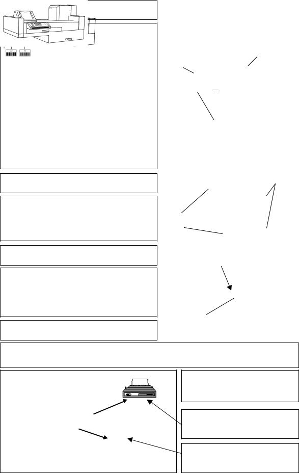
CPM operation of WIZARD®3’’
1 Fix ID clips to racks
ID labels (barcodes) are stuck to an ID clip which fits onto a rack to tell WIZARD the function of the rack.
A counting protocol is a set of three parameters time, max. counts limit and isotope, which control counting.
Rack number is optional and allows each rack to have its own number.
Normalization ensures that the gain of the detector is optimum for each isotope and energy range. Background ensures that the effect of the background is removed from the measured counts.
Test initiates a GLP performance test normalization.
Isotope number shows the isotope to be used in normalization.
Stop tells WIZARD that no more racks are to be counted.
2 Load racks onto WIZARD
Make sure that tube holders are positioned correctly and that racks are loaded the correct way round with the ID clips facing away from you as shown in the figure. Start by loading the right-hand side of the conveyor.
3 Press START to count
Live display during counting is obtained by selecting from the main menu on the WIZARD built-in display "Operate" and then "Show cpm results". Available live displays are: counting parameters, Counts, CPM, CPS and Spectrum.
Make sure tube holders are the right way round
Position 1
Fix ID clip here
Protocol, isotope or energy range number
Rack number or NORM, TEST, BKG or STOP instruction
ID clip faces forward when loading racks
Position 1
Live display available during counting
START
4 Results are printed out
The built-in program allows counting and normalization protocols to be created and edited. The built-in display and keyboard is used. Results are sent to the display and a printer.
For System setting info. e.g. detector deactivation or clock setting select SYSTEM in the main menu
The printer connected to WIZARD port 1 is used for printing corrected CPM results directly from WIZARD.
A disk can be used for transferring results from WIZARD
9

RiaCalc WIZ operation of WIZARD®3’’
1 Fix ID clips to racks
ID labels (barcodes) are stuck to an ID clip which fits onto a rack to tell WIZARD the function of the rack.
A counting protocol is a set of three parameters time, max. counts limit and isotope, which control counting.
Rack number is optional and allows each rack to have its own number.
Normalization ensures that the gain of the detector is optimum for each isotope and energy range. Background ensures that the effect of the background is removed from the measured counts.
Test initiates a GLP performance test normalization.
Isotope number shows the isotope to be used in normalization.
Stop tells WIZARD that no more racks are to be counted.
2 Load racks onto WIZARD
Make sure that tube holders are positioned correctly and that racks are loaded the correct way round with the ID clips facing away from you as shown in the figure. Start by loading the right-hand side of the conveyor.
3 Press START to count
Live display during counting is obtained by selecting from the main menu on the WIZARD built-in display "Operate" and then "Show cpm results". Available live displays are: counting parameters, Counts, CPM, CPS and Spectrum. You can also see RiaCalc WIZ output by choosing the "Show evaluation results"
4functionResults. are printed out
Make sure tube holders are the right way round
Position 1
Fix ID clip here
Protocol, isotope or energy range number
Rack number or NORM, TEST, BKG or
STOP instruction
ID clip faces forward when loading racks
Position 1
Live display available during counting
START
The built-in program allows counting and normalization protocols to be created and edited. The built-in display and keyboard is used. Results are sent to the display and a printer.
11 |
For System setting info. e.g. detector deactivation or clock setting select SYSTEM in the main menu
The printer connected to WIZARD port 1 is used for printing corrected CPM results directly from WIZARD
A disk can be used for transferring results from WIZARD
External keyboard in built-in drawer for extended protcol editing
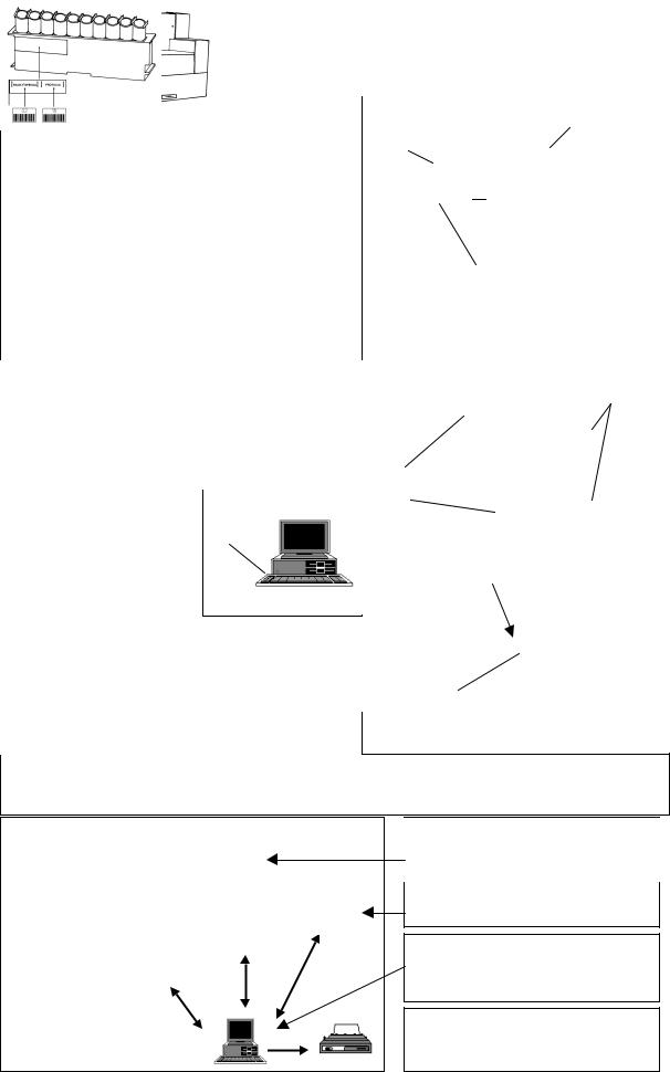
MultiCalc® operation of WIZARD®3’’
1 Fix ID clips to racks
ID labels (barcodes) are stuck to an ID clip which fits onto a rack to tell WIZARD the function of the rack. A counting protocol is a set of three parameters time, max. counts limit and isotope, which control counting. Rack number is optional and allows each rack to have its own number.
Normalization ensures that the counting efficiency of each detector is the same.
Background ensures that the effect of the background is removed from the measured counts.
Test initiates a GLP performance test normalization. Isotope number shows the isotope to be used in normalization.
Stop tells WIZARD that no more racks are to be counted.
2 Load racks onto WIZARD
Make sure racks are loaded the correct way round with the ID clips facing away from you as shown in the figure. Start by loading the right-hand side of the conveyor.
Make sure tube holders are the right way round
Position 1
Fix ID clip here
Protocol, isotope or energy range number
Rack number or NORM, TEST, BKG or STOP instruction
ID clip faces forward when loading racks
Position 1
3 Press F1 (COUNTER) F1 select 1480 and press Enter
Live display during counting is obtained by selecting from the main menu on the WIZARD built-in display "Operate" and then "Show cpm results". Available live displays are: counting parameters, Counts, CPM, CPS and Spectrum. These appear on the built-in display.
4 Results go to MultiCalc
Live display available during counting
START
MultiCalc is a very versatile data handling program which runs on an external computer. You can use it to make counting protocols. These will be transferred to WIZARD to control counting. Results are returned to MultiCalc for evaluation. They can also be sent, via MultiCalc, to a local area network (LAN) or mainframe.
LAN
Output to external computer e.g. a mainframe. Connection is from the mainframe to the PC
Local area network connection (LAN) using the PC
Results go to the PC connected to port 2. Printout goes to the printer connected to the PC
For System setting info. e.g. detector de-activation or clock setting select SYSTEM in the main menu
13
2 WIZARD controls
15
2 WIZARD controls
2 WIZARD controls
2.1 Introduction
This chapter describes features you need to use to control WIZARD. These features are: the one or two keyboards, the display, the ID system and the HELP function. When you understand how to use these features then you can proceed to the following chapters to see how to use WIZARD to get the results you want.
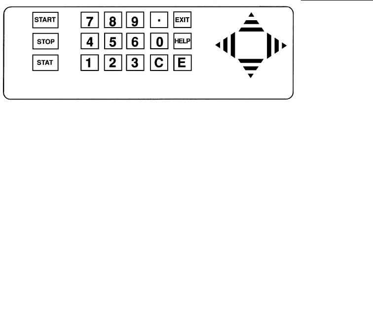
2.2 Keyboard
WIZARD can have two keyboards, a simple membrane type on the front of the instrument (see the figure below) and a second, a complete PC keyboard, which is in a separate compartment. The instrument is normally operated using the small keyboard whereas the larger keyboard is used for extended protocol editing because the small keyboard does not include letters and certain other characters which are needed in some editing operations.
The keyboards are connected in parallel with each other and each key on the built-in keyboard has its equivalent on the external one. The keys on the external keyboard which correspond to those on the built-in keyboard are as follows:
Built-in keyboard External keyboard
START |
F3 |
STOP |
F4 |
STAT |
F5 |
HELP |
F1 |
EXIT |
ESC |
C (Clear) |
Backspace |
E |
Enter |
Use the EXIT (ESC) to escape from the operating level the program is on and go back to the previous one.
If you are using a PC running MultiCalc all commands involving MultiCalc are given via the PC keyboard.
17

2 Wizard controls
2.3 Display
2.3.1Main menu display
When you start to work with the instrument you will see on the built-in display something like:
==1480 Main Menu===================== OPERATE PROTOCOL FILES SYSTEM ==Submenu===========================
Show cpm results
Show evaluation results
Operate conveyor
==Cpm============================== Press START to measure
2.3.2Function selection
The line in capital letters shows four major functions of which the first, OPERATE, is currently selected. The following lines show the commands available as part of that function. Each function has its own set of commands. You can select the function with the left and right arrow keys. The individual command is selected with the up and down arrow keys. To give the selected command to WIZARD press the E key
2.3.3Enabled and disabled functions
On the example screen shown above the first two command lines are in subdued colour. This indicates that the counter is not measuring and hence these functions are not enabled. The third item on the menu "Operate conveyor" is however available.
2.3.4Operating the conveyor
If you select this and press E the display changes to:
--Operate conveyor-------------------------------------
Move racks to output line
Move racks to input line
Move both lines forwards
Move both lines backwards
Move all lines clockwise
Rotate all lines counterclockwise
Clear conveyor
--Press-START ---------------------------------------
By selecting from this menu and pressing E you can control the movement of racks on the conveyor. To return to the main display, press EXIT.
18

2 WIZARD controls
2.3.5Selecting the current mode
WIZARD can be used in one of three modes: CPM, MultiCalc or RiaCalc WIZ. The current mode is shown on the lower part of the main menu display. The example on the previous pages shows that the Cpm mode is selected.
2.3.6Status line
At the bottom of the screen there is a status line. This shows what is being measured. In the display example above the status line is "Press START to measure". The status line can have the following texts:
Press START to measure
Measuring an assay
Measuring background
Normalizing
Clearing the conveyor
Seeking assay
GLP test
2.4 Live display
When samples are being counted the display can show actual counting values, either collected counts, collected counts per minute (CPM values) or a complete isotope spectrum. The word "Live" indicates that the display is working in real time; values are updated at the same pace as counts are accumulated.
2.4.1How to use the Live display
In order that the Live display works, the counting must be actually happening.
Select the OPERATE menu. The status line must show "Measuring assay" or a corresponding text that indicates that counting is active. Select "Show cpm results" and press the "E" key. Counting parameters are shown (see the figure below).
2.4.2Display modes.
There are five display modes (Note: there are two counting windows in dual channel counting):
--Show cpm results------------------------------------- |
|
Measuring now, elapsed time is = 19 s. |
|
--Counting parameters---------------------------------- |
|
Measurement |
Assay |
Protocol |
11 PROT03 |
Label |
I-125 |
Preset time |
60 |
Counts limit |
9999999 |
Batch number |
2 |
--Change data with ← → keys---------------------- |
|
19

2 Wizard controls
Counting parameters (as shown above)
COUNTS |
Accumulated counts in counting window |
CPM |
Counts per minute in the counting window |
CPS |
Counts per second in the counting window |
Spectrum display
Select the appropriate one using the "right" and "left" arrow keys. Pressing the right key twice initiates the CPM display
Assay (Auto mode)
Measuring now, elapsed time is = 30 s.
Isotope Count per minute
I-125 5555.3
The example is from CPM counts; the display for COUNTS and for CPS are analogous to the CPM display.
Note: CPM values are not corrected for dead time, background, spillover or detector efficiency but are direct values of accumulated counts divided by measured time.
2.4.3Displaying the isotope spectrum
When you press”E” the spectrum is displayed. The detector spectrum display is a graphical representation of isotope activity with respect to isotope energy. The X-axis shows the energy in keV (up to 1024 or 2048 depending on the energy range) and the Y-axis shows the accumulated counts in each individual channel. The
|
LIVE SPECTRUM 1 |
X scale = MCA |
|
|
|
|
|
|
|
|
|
total counts in full window 76352
20

2 WIZARD controls
analyzer is initially adjusted so that each channel corresponds to 1 keV, therefore the X-axis is approximately from 0 to 1 MeV.
Scale in channels or keV - The X-axis scale can be in channels or in keV. To flip from one mode to the other, press "E" when the spectrum is displayed.
2.4.4Spectrum functions
On the right hand side of the spectrum five functions are displayed. By using the up and down arrow keys, you can select the function you want. A function is shown to be selected by the underline mark appearing under the function name. The functions are as follows:
Scale - This allows you to select the scale for the spectrum. The default is 1 - 1024. By pressing the left arrow you can change the scale to 0..512, 0..256, 0..128, or 0..64. To return to fuller scales, press the right arrow. The figure shows the 0..64 scale. See the next function "Shift" for how to move through the scale segments.
Shift - If the scale used is less than full scale (0 - 1024 or 1 – 2048, e.g. 0 - 256), you can use the "shift" function to move the spectrum to see other parts which otherwise would not be displayed e.g. 256 - 512 etc.
Marker – If you have one of the basic scales (1 – 1024 or 1 – 2048) selected you can use this function to select a marker which you can then move with the arrow keys to mark any position in the spectrum. In this way you can find out the exact position of any peak.
WinLo and WinHi - These allow you to set an upper and lower window limit marker so that you can obtain the counts within the window.
You can also print out the spectrum if you press "Print screen" on the external keyboard provided CAPS LOCK is not on and there is a printer connected.
Spectra can also be printed via MultiCalc to the printer that is connected to the PC running MultiCalc.
To do this, the following conditions must be met: If the instrument is in "MultiCalc" mode, then MultiCalc itself must be in online mode when the Print Screen key is pressed. If the instrument is in "Cpm" or "RiaCalc WIZ" mode, then the instrument parameter "SYSTEM | Printout options | Without buffering PC" must be "YES" and MultiCalc must be receiving data from the counter.
Spectra are printed correctly only if in the WIZARD communication protocol the Terminal parameter is VT-52.
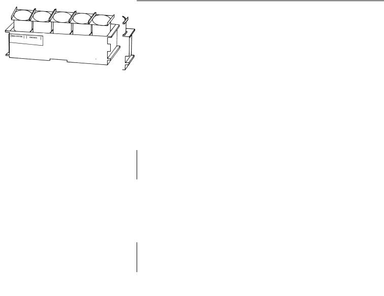
2.5 Racks
WIZARD takes two types of rack, one which takes 5 x 28mm samples and the other which takes 10 x 13mm samples, see the figures of the racks on page 24. You can have any mix of these racks on the conveyor because WIZARD automatically determines the rack type and adjusts the sample loading mechanism each time a rack is taken in to the loading position.
2.6 Principle of the ID system
WIZARD is an automatic gamma counter. This means that samples from several assays can be loaded onto the conveyor and WIZARD can be left to count them by itself. To do this it needs to be able to identify each batch of samples. The WIZARD ID system uses a plastic clip onto which one or two barcode labels are stuck. The clip is then clipped onto the rack to be identified. The clip can easily be removed and a new one fitted when required.
The barcodes give information to WIZARD about e.g. which counting protocol is to be used for the samples, what the rack number is etc. Only the first rack in an assay needs to have a protocol label. Barcodes are to be found in a booklet supplied with the counter. There are two classes of barcodes, numerical ones (0 ... 99) and instruction
21

2 Wizard controls
ones. The figure above shows an empty clip and then several examples of clips with labels on them. Some have two labels and some only one.
In addition there is a third area of the clip which comes on the end of the rack. This can be used for you to write your own information on. The ID label booklet includes empty labels for you to write on and stick to the clip. There are also barcodes marked PCURVE and CONTROL which are not used in this program.
Empty clip
Clip with rack number (02) and protocol number (18)
Clip with normalization instruction and isotope code number 02
Clip indicating a background measurement to be made
Clip indicating that counting is to stop after counting this rack if it contains samples. If it is empty counting will stop immediately
2.7 Fitting ID labels
The figures below show two types of rack with an empty ID clip fitted on them. There is a special recess on one side of each rack. This is where the clip fits. It will not fit to the other end of the rack. This is important because it defines which way round the rack should be on the conveyor. Make sure the ID clip is fitted properly so that it does not slip off when the rack is on the conveyor.
22
2 WIZARD controls
Empty clip fitted onto rack
Empty clip fitted onto rack
2.8 Loading racks the right way round
When you load racks on the conveyor the ID labels must face away from you with the white dot on the right side as shown in the figures on the next page. The handwritten information on the label at the end of the rack is then clearly visible from the side of the conveyor.
23

2 Wizard controls
All racks, even those without labels, must be put the same way round with the recess for the label (and white spot)on the right hand side when you load the racks. If a rack is not the right way round a warning is displayed and counting is stopped until the rack has been turned the right way round.
Make sure the tube holders are the right way round, see the figures.
Direction of movement on |
|
the conveyor |
White dot |
|
Rack orientation when loaded onto the conveyor
Direction of movement on the conveyor 
Rack orientation when loaded on the conveyor
Information written by the user on the ID label
White dot
Information written by the user on the ID label
24
Loading...