


 Loading...
Vectra PolarisTM
User Manual
P/N CLS147553 Rev. G
Publication Date: July 27, 2018

Instrument Safety |
2 |
Instrument Safety
The following safety information about the Vectra Polaris is included in this documentation. Read and review all safety information before operating the Vectra Polaris.
•Required Training
•Electrical Safety
•Mechanical Safety
•Weight Warning
•Bright Light
Required Training
Ensure that all personnel involved with the operation of the instrument have:
•Received instruction in general safety practices for laboratories.
•Received instruction in specific safety practices for the instrument.
WARNING
Use this product only in the manner described in this manual. If the equipment is used in a manner not specified by the manufacturer, the protection provided by the equipment may be impaired.
P/N CLS147553 Rev. G |
Vectra Polaris User Manual |
PerkinElmer, Inc. |

Instrument Safety |
3 |
Electrical Safety
The Vectra Polaris is powered by a 100-120VAC/200-240VAC, 5060Hz (±10%) input power supply.
The wall outlet or the power cable connector on the left side of the instrument should be accessible after the system's installation, to enable trained service personnel to safely disconnect power from the system during servicing.
WARNING
Do not operate the system in an environment with explosive or flammable gases.
WARNING
•DO NOT remove instrument covers. There are no user serviceable parts inside. The covers are intended to be removed only by qualified PerkinElmer service personnel; they are not intended to be removed during operation or for maintenance by users. Contact PerkinElmer technical support if help is required (see page 7).
•Do not operate the system if there has been a malfunction of the system door or slide loading components. Contact PerkinElmer technical support if help is required (see page 7).
•Do not operate the system in places where it may be splashed with liquid.
For further electrical safety information, refer to the following sections:
•Power Cord Selection
•Fuses
•Cables and Adapters
Power Cord Selection
Contact PerkinElmer Technical Support (see page 7) to order replacement power cords.
P/N CLS147553 Rev. G |
Vectra Polaris User Manual |
PerkinElmer, Inc. |

Instrument Safety |
4 |
WARNING
•Use only the power supply cord set provided with the Vectra Polaris system. If the correct cord set for the location was not provided, contact PerkinElmer Technical Support (see page 7) for a replacement. Do not use power supply cords with inadequate ratings.
•Use only a properly grounded power outlet when connecting the system to power.
Fuses
Contact PerkinElmer Technical Support (see page 7) to order replacement fuses.
WARNING
The fuses in this instrument are only replaceable by trained
PerkinElmer personnel.
Cables and Adapters
Some cables and adapters supplied with the system have proprietary specifications.
WARNING
Do not connect components supplied by PerkinElmer using unqualified cables or adapters. Contact PerkinElmer technical support (see page 7) to order replacement cables and adapters.
Mechanical Safety
WARNING
Instrument components may move during operation. Always keep body parts, hair, jewelry, and clothing away from the instrument during operation.
P/N CLS147553 Rev. G |
Vectra Polaris User Manual |
PerkinElmer, Inc. |

Instrument Safety |
5 |
WARNING
Procedures which could result in injury may be performed only by operators who have been warned of the potential hazards and have received adequate training in performing the procedures in the safest possible manner.
Weight Warning
WARNING
LIFTING HAZARD. The Vectra Polaris instrument weighs 185 lbs. (84 kg). Do not move the Vectra Polaris instrument. Installing, servicing, and moving the Vectra Polaris instrument should be performed only by qualified PerkinElmer service personnel. Contact PerkinElmer technical support if help is required (see page 7).
Bright Light
WARNING
BRIGHT LIGHT HAZARD. The interior of the Vectra Polaris system includes a barcode reader with a Class 2 LED Light. Do not look into the bright light to avoid eye injury.
CAUTION - CLASS 2 LASER RADIATION WHEN OPEN
DO NOT STARE DIRECTLY INTO THE BEAM
P/N CLS147553 Rev. G |
Vectra Polaris User Manual |
PerkinElmer, Inc. |

Preface 6
Preface
Copyright
This manual is published by PerkinElmer, Inc., 68 Elm Street, Hopkinton, MA 01748 USA. Copyright 2017-2018, PerkinElmer, Inc., and its parent, affiliated, and subsidiary companies. All rights reserved, including but not limited to those rights to reproduce this publication or parts thereof. Reproduction of this publication or parts thereof, or the products it describes, by any means or in any form is expressly prohibited without the written permission of PerkinElmer.
Trademarks
PerkinElmer is a registered trademark of PerkinElmer, Inc. Microsoft and Windows are either registered trademarks or trademarks of Microsoft Corporation in the United States and/or other countries. All other trademarks are the property of their respective owners.
Patents
US Patents 5,892,612; 5,953,087; 7,655,898; and patents pending.
Content
Any errors or omission which may have occurred in this publication despite the utmost care taken in its production will be corrected as soon as possible, but not necessarily immediately upon detection. PerkinElmer provides this publication “As Is” without warranty of any kind, either express or implied, including but not limited to the implied warranties of merchantability or fitness for a particular purpose. Some states or jurisdictions do not allow disclaimer of express or implied warranties in certain transactions; therefore, this statement may not apply to you. PerkinElmer reserves the right to revise this publication and to make changes from time to time in the content hereof without obligation of PerkinElmer to notify any person of such revision or changes. Further, PerkinElmer may make modifications to the product described in this manual at any time without any obligation to notify any person of such modifications.
Proper Equipment Operation
WARNINGS
•To reduce the risk of electric shock, do not remove the instrument panels. No user serviceable parts are inside. Refer to qualified service personnel if help is required.
•Use this product only in the manner described in this manual. If the equipment is used in a manner not specified by the manufacturer, the protection provided by the equipment may be impaired.
AVERTISSEMENTS
•Pour réduire le risque de choc électrique, ne pas retirer le couvercle. Ce produit ne contient aucune pièce pouvant être réparée par l’utilisateur. Au besoin, confier l’appareil à un réparateur qualifié.
P/N CLS147553 Rev. G |
Vectra Polaris User Manual |
PerkinElmer, Inc. |

Preface 7
•Ce produit ne doit être utilisé que comme décrit dans ce manuel. Si cet appareil est utilisé d’une manière autre que celle spécifiée par le fabricant, la protection fournie par l’appareil peut être entravée.
Contact Us
If you have a question about a product that is not answered in this manual or online Help, or if you need assistance regarding this product, please contact the PerkinElmer Technical Support Center from 8:00 A.M. to 8:00 P.M., Eastern Time, Monday through Friday:
Phone: (US Toll Free): 800-762-4000
(Worldwide): +1 203-925-4602 Fax: +1 203-944-4904
Email: global.techsupport@perkinelmer.com Internet: www.perkinelmer.com
Before you call, have the following information available for the technical representative:
•Product serial number
•Software version (found by choosing About from the main Help menu)
•If applicable, the error number shown on the product’s LCD display, in the software, or in the log file.
Product Service and Customer Support Plans
PerkinElmer offers a full range of services to ensure your success. From our original factory warranty through a comprehensive line of customer support plans, PerkinElmer offers you Field Service Engineers and in-house Specialists who are dedicated to supporting your hardware, software, and application development needs.
Phone: (US Toll Free): 800-762-4000
(Worldwide): +1 203-925-4602 Fax: +1 203-944-4904
Email: global.techsupport@perkinelmer.com Our programs can include such useful services as:
•Preventive maintenance
•Diagnostic servicing performed on-site by PerkinElmer field service engineers or remotely via Technical Support
•Validation performed on-site by PerkinElmer field service engineers
•Extended use of the PerkinElmer Technical Support Center
•Software updates
•Parts, labor, and travel expense coverage
•Other customized services upon request
Training For Your Product
Contact PerkinElmer for information about the availability of training courses for your product:
Phone: (US Toll Free): 800-762-4000
(Worldwide): +1 203-925-4602 Fax: +1 203-944-4904
P/N CLS147553 Rev. G |
Vectra Polaris User Manual |
PerkinElmer, Inc. |
Preface 8
CE
This device complies with all CE rules and requirements.
NOTE
Changes or modifications to this equipment not expressly approved by the party responsible for compliance could void the user’s authority to operate the equipment.
REMARQUE
Tout changement ou modification apporté à cet instrument non expressément approuvé par l’entité responsable de la conformité peut annuler l’autorisation d’opérer l’appareil accordée à l’utilisateur.
KC
This device complies with MSIP (Ministry of Science, ICT, and Future Planning) EMC Registration requirements. This instrument is registered as a Class A instrument for business use only. Product seller and user should notice that this equipment is not for household use.
P/N CLS147553 Rev. G |
Vectra Polaris User Manual |
PerkinElmer, Inc. |
Preface 9
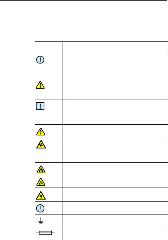
Table of Symbols
Table 1 contains symbols that identify particularly important information and alert you to the presence of hazards. These symbols may appear in this manual and/or on the product it describes.
Table 1. Important Symbols
Symbol Description
Symbole Description
DANGER: An imminently hazardous situation, which, if not avoided, will result in death or serious injury.
DANGER: Situation présentant un danger imminent qui, s’il n’est pas éliminé, peut entraîner des blessures graves, voire la mort.
WARNING: Caution. Refer to the User’s documentation. (ISO 7000-0434B)
AVERTISSEMENT: Attention. Se reporter à la documentation de l’utilisateur.
NOTE: A cautionary statement; an operating tip or maintenance suggestion; may result in instrument damage if not followed.
REMARQUE: Énoncé indiquant une précaution à prendre, un conseil de fonctionnement ou une suggestion d’entretien; son non-respect peut provoquer des dommages à l’instrument.
Hazardous voltage; risk of electric shock. (IEC 60417-6042)
Tension dangereuse; risque de blessure par électrocution.
Crush hazard. Risk of body parts, hair, jewelry, or clothing getting caught in a moving part. (ISO 3864)
Danger d’écrasement. Faire attention que les parties corporelles, les cheveux, les bijoux ou les vêtements ne soient pas pris dans une pièce mobile.
Risk of fire. (ISO 3864)
Risque d’incendie.
Risk of explosion. (ISO 3864)
Risque d’explosion.
Lifting hazard. May result in injury. (ISO 3864)
Levage dangereux. Peut entraîner des blessures.
Protective ground symbol. (IEC 60417-5019)
Symbole de terre de protection.
Ground symbol. (IEC 60417-5017)
Symbole de terre.
Fuse. (IEC 60417-5016)
Fusible.
P/N CLS147553 Rev. G |
Vectra Polaris User Manual |
PerkinElmer, Inc. |
Preface 10
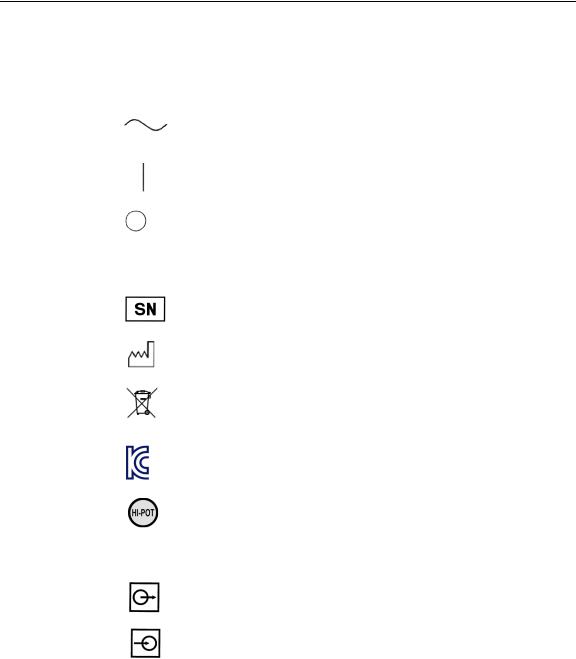
Table 1. Important Symbols (Continued) |
||
|
|
|
Symbol |
Description |
|
Symbole |
Description |
|
|
|
|
|
Alternating current. (IEC 60417-5032) |
|
|
Courant alternatif. |
|
|
|
|
|
On (power). |(IEC 60417-5007) |
|
|
Marche (alimentation). |
|
|
|
|
|
Off (power). (IEC 60417-5008) |
|
|
Arrêt (alimentation). |
|
|
|
|
|
CE compliance mark. |
|
|
Marque de conformité CE. |
|
|
|
|
|
Serial Number (ISO 7000-2498) |
|
|
Numéro de série. |
|
|
|
|
|
Date of Manufacture. (ISO 7000-2497) |
|
|
Date de fabrication. |
|
|
|
|
|
WEEE symbol (EN50419:2005). Do not dispose of as unsorted |
|
|
municipal waste. See the PerkinElmer website |
|
|
(www.perkinelmer.com) for more information. |
|
|
|
|
|
Unified Korea Certification Mark (KC Mark) |
|
|
|
|
|
Signifies that the unit has passed safety tests for grounding, |
|
|
power line transience, and current leakage. |
|
|
Signifie que l’appareil a réussi les tests de sécurité pour la mise |
|
|
à la terre, le courant transitoire de ligne d’alimentation et la |
|
|
perte de courant. |
|
|
|
|
|
Input. |
|
|
Entrée. |
|
|
|
|
|
Output. |
|
|
Sortie. |
|
|
|
|
Equipment |
Yellow |
Caution, risk of danger |
labels are color |
Red |
Stop |
coded: |
Blue |
Mandatory action |
|
Green Safe condition or information |
|
Les étiquettes |
Jaune |
Attention, danger potentiel |
de l’appareil |
Rouge Arrêter |
|
sont codées |
Bleu |
Intervention obligatoire |
couleur: |
Vert |
Condition sûre ou informations de sécurité |
|
|
|
P/N CLS147553 Rev. G |
Vectra Polaris User Manual |
PerkinElmer, Inc. |
|
11 |
Table of Contents |
|
Instrument Safety ................................................................................................... |
2 |
Required Training................................................................................................ |
2 |
Electrical Safety .................................................................................................. |
3 |
Power Cord Selection .................................................................................... |
3 |
Fuses ............................................................................................................ |
4 |
Cables and Adapters ..................................................................................... |
4 |
Mechanical Safety ............................................................................................... |
4 |
Weight Warning................................................................................................... |
5 |
Bright Light.......................................................................................................... |
5 |
Preface .................................................................................................................... |
6 |
Introduction........................................................................................................... |
13 |
Intended Use..................................................................................................... |
13 |
Principles of Operation ...................................................................................... |
14 |
Example Applications................................................................................... |
16 |
Theory of Imaging ............................................................................................. |
16 |
Light ............................................................................................................ |
17 |
Human Perception of Light Intensity and Color ............................................ |
18 |
Light Absorbance and Reflection ................................................................. |
19 |
Fluorescence ............................................................................................... |
20 |
Photobleaching ............................................................................................ |
21 |
Filter Sets for Conventional vs. Multispectral Imaging .................................. |
22 |
Multispectral Analysis .................................................................................. |
24 |
Whole Slide Scanning ....................................................................................... |
27 |
Multispectral Imaging ........................................................................................ |
29 |
Hardware Reference ............................................................................................. |
30 |
Front View......................................................................................................... |
31 |
Top View ........................................................................................................... |
33 |
Right-Side View................................................................................................. |
34 |
Left-Side Connectors......................................................................................... |
35 |
Slide Carrier Hotel............................................................................................. |
36 |
Slide Carrier ...................................................................................................... |
38 |
Barcode Reader ................................................................................................ |
39 |
System Computer and Monitor .......................................................................... |
40 |
System Computer Connectors ..................................................................... |
40 |
Specifications .................................................................................................... |
41 |
Hardware Operation.............................................................................................. |
43 |
System Startup.................................................................................................. |
44 |
Turn on the Vectra Polaris Instrument.......................................................... |
44 |
Launch the Vectra Polaris Software ............................................................. |
44 |
System Shutdown ............................................................................................. |
45 |
Inspecting Slides and Slide Carriers .................................................................. |
45 |
Inspect Slides .............................................................................................. |
45 |
P/N CLS147553 Rev. G |
Vectra Polaris User Manual |
PerkinElmer, Inc. |

|
12 |
Inspect Slide Carriers .................................................................................. |
45 |
Loading Slides into the Slide Carriers................................................................ |
46 |
Loading Slide Carriers into the Slide Carrier Hotel............................................. |
47 |
Removing Slide Carriers from the Slide Carrier Hotel ........................................ |
49 |
Removing Slides from the Slide Carriers ........................................................... |
49 |
Software Operation ............................................................................................... |
50 |
Software Overview ............................................................................................ |
51 |
Check Dashboard ........................................................................................ |
52 |
Edit Protocol ................................................................................................ |
52 |
Scan Slides ................................................................................................. |
52 |
Launch Phenochart...................................................................................... |
52 |
Gear Menu................................................................................................... |
53 |
System Dashboard ............................................................................................ |
54 |
Disk Space .................................................................................................. |
54 |
Brightfield References ................................................................................. |
54 |
Fluorescence References ............................................................................ |
56 |
Compensation Information ........................................................................... |
57 |
Creating and Editing Protocols .......................................................................... |
58 |
Studies ........................................................................................................ |
58 |
Creating Protocols ....................................................................................... |
59 |
Editing Protocols.......................................................................................... |
60 |
Scanning Slides ................................................................................................ |
78 |
The Carrier .................................................................................................. |
78 |
Carrier Status .............................................................................................. |
78 |
Slide Status ................................................................................................. |
80 |
Setting Up Scan Rules ................................................................................. |
80 |
Maintenance .......................................................................................................... |
89 |
Cleaning the Instrument Exterior ....................................................................... |
89 |
Cleaning the Monitor ......................................................................................... |
90 |
Cleaning the Power and Communication Ports .................................................. |
90 |
Cleaning the Slide Carriers................................................................................ |
90 |
Replacing the Fuses.......................................................................................... |
90 |
Appendix A: PerkinElmer TIFF Specification ...................................................... |
91 |
PerkinElmer Software License Agreement .......................................................... |
97 |
Index .................................................................................................................... |
107 |
P/N CLS147553 Rev. G |
Vectra Polaris User Manual |
PerkinElmer, Inc. |

Introduction 13
Introduction
This manual describes the use and functionality of the Vectra Polaris Automated Quantitative Pathology Imaging System. It includes operating instructions, functional descriptions, troubleshooting, illustrations, and other relevant information.
This section of the manual contains the following topics:
•Intended Use
•Principles of Operation
•Theory of Imaging
•Whole Slide Scanning
•Multispectral Imaging
Intended Use
The Vectra Polaris is a multimodal digital pathology instrument that integrates both multispectral analysis and automated slide scanning that allows researchers to visualize, analyze, quantify and phenotype immune cells in situ in FFPE tissue sections and TMAs.
NOTE
PerkinElmer's Vectra Polaris Quantitative Pathology Imaging System is for research use only. Not for use in diagnostic procedures.
P/N CLS147553 Rev. G |
Vectra Polaris User Manual |
PerkinElmer, Inc. |
Introduction 14
Principles of Operation
PerkinElmer’s Vectra Polaris is an automated imaging system for performing whole slide scans of tissue sections and microarrays (TMAs), and for acquiring multispectral (MSI) regions of interest. The system has been optimized to image samples stained with PerkinElmer’s Opal multiplexed fluorescent immunohistochemistry reagent kits and is also compatible with typical brightfield staining reagents.
The Vectra Polaris is configured to store and inventory up to 20 slide carriers, each holding up to 4 tissue slides, for a total of 80 slides.
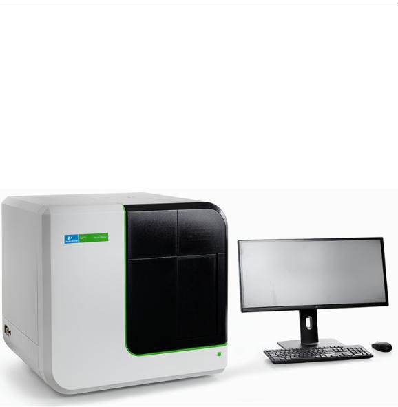
Figure 1. The Vectra Polaris System
The Vectra Polaris has been designed to expand and support the workflow defined in PerkinElmer’s Vectra® 3:
•True whole slide scanning of slides at 1.0 um/pix, 0.5 um/pix, and 0.25um/pix
•Review and annotation of whole slides scans for MSI acquisition
•Acquisition of MSI regions
•Analysis of MSI regions including protein expression and phenotyping
P/N CLS147553 Rev. G |
Vectra Polaris User Manual |
PerkinElmer, Inc. |

Introduction 15
To implement the full capabilities of the instrument and workflow, the Vectra Polaris system includes the following PerkinElmer software:
•Vectra Polaris: Operator-centric software for performing whole slide scans and acquiring MSI regions of interest. The Vectra Polaris software runs on the workstation connected to the Vectra Polaris instrument.
•Phenochart : Whole-slide viewer and annotator of fluorescent and brightfield scans acquired by the Vectra Polaris. Phenochart allows the user to view the whole slide (zoom, pan, etc.), and make decisions (annotations) on next steps for the sample. Annotations in Phenochart are also used to record the workflow actions for each slide scan. Annotations include reviewer requested MSI fields; automated (inForm) field requests; and reviewer edits, approvals, and rejections. The annotation file is a fully auditable transaction log. Phenochart is freely distributed and can be used by multiple users who wish to view or review slide scans taken by the Vectra Polaris.
•inForm® Tissue Finder: Software typically used for the analysis of MSI images. inForm supports features such as tissue classification and training, cell phenotyping, protein expression measurements, and data export. It can be run on the Vectra Polaris computer and other Microsoft® Windows 10 computers. Additional inForm software “seats” beyond the two seats that come with each Vectra Polaris system are available for purchase.
Vectra Polaris workflows range from simple two-step procedures (e.g., acquire whole slide scan and review) to automated acquisition of regions of interest selected by the user or the Vectra Polaris itself. An example fluorescence workflow might include the following steps:
1Stain tissue with PerkinElmer Opal fluorescent IHC reagents.
2Acquire whole slide fluorescent imagery using the Vectra Polaris.
3Review the whole slide imagery with Phenochart and annotate regions of interest for MSI analysis.
4Acquire the MSI regions with Vectra Polaris.
5Use inForm to phenotype cells and measure protein expression levels in the acquired MSI regions.
For example applications for the Vectra Polaris, see Example Applications.
P/N CLS147553 Rev. G |
Vectra Polaris User Manual |
PerkinElmer, Inc. |

Introduction 16
Example Applications
Some examples of Vectra Polaris applications include:
•Whole slide scanning and multispectral interrogation of tissue samples and microarrays stained with Opal reagent kits
•Whole slide scanning of tissue samples stained with H&E and conventional IHC stains
•Phenotypic analysis and protein expression of immune and cancer cells in the context of the tumor microenvironment.
Theory of Imaging
This section introduces some important concepts used by
PerkinElmer’s Vectra Polaris imaging systems, including:
•Light
•Human Perception of Light Intensity and Color
•Light Absorbance and Reflection
•Fluorescence
•Photobleaching
•Filter Sets for Conventional vs. Multispectral Imaging
•Multispectral Analysis
P/N CLS147553 Rev. G |
Vectra Polaris User Manual |
PerkinElmer, Inc. |
Introduction 17
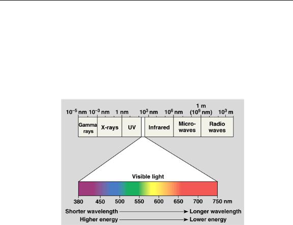
Light
For purposes of this discussion, light refers to the part of the electromagnetic spectrum that can be seen by the human eye and the nearby ultraviolet and infrared wavelengths. While the physical description of light can be highly complex, we will focus on these wavelengths of light and how they interact with physical and biological materials.
Figure 2. The Electromagnetic Spectrum
P/N CLS147553 Rev. G |
Vectra Polaris User Manual |
PerkinElmer, Inc. |

Introduction 18
Human Perception of Light Intensity and Color
Response to Illumination
The human eye is a highly adaptive light detector. It is significantly more sensitive in low light than in bright light. When light levels change, it takes some time for the eye to fully adjust. This is the reason people need to “dark adapt” in a darkened room before they are able to observe weak fluorescence through a microscope.
Humans can see both in very dark and very bright settings. Because the eye is so adaptable to various lighting conditions, humans are unable to quantify absolute levels of light. In any given situation, the eye has a limited ability to discriminate levels of illumination. US Department of Defense research indicates that most humans can only distinguish approximately 30 to 35 levels of gray, ranging from black to white.
The eye's response to illumination is not linear. It more closely approximates a logarithmic function. The result is that the human eye cannot see small proportional changes in brightness.
Contrasting the eye with conventional microscope imagery, any sensor that has 8-bit resolution can detect 256 levels of gray. As the number of bits of resolution increase, the number of gray levels also increases. A 12-bit sensor yields 4096 levels of gray. Digital electronic sensors are linear in response to light levels.
Ability to Distinguish Colors
While the eye is relatively poor at discriminating intensity, it is very good at distinguishing colors. Most individuals are able to discriminate thousands of colors. However, no two individuals see a given color in exactly the same way. The eye contains three different types of color sensors, also known as cone cells. While the arrangement of cone cells is generally standard from person to person, the ratio of each type of cone cell varies, as does their actual physical arrangement within the eye. These minor variations (along with the brain's interpretation of the color) lead to the differences in perceived color between individuals.
P/N CLS147553 Rev. G |
Vectra Polaris User Manual |
PerkinElmer, Inc. |

Introduction 19
Light Absorbance and Reflection
We perceive objects based on the way they transmit, absorb, and/or reflect light.
Absorbance and reflection work in tandem. Absorbance refers to the wavelengths of light that are 'taken in by' the objects. This means that an object that we perceive as red has absorbed all visible wavelengths of light except red. The red wavelengths are reflected back to the eye of the observer.
Transmittance refers to light emitting objects such as light sources, and fluorescing or phosphorescing objects. An object we would perceive as red in transmission is one that transmits primarily red wavelengths, while absorbing or reflecting other wavelengths.
In brightfield light microscopy we observe light that passes through a specimen. Except for a few pigments and inclusions, biological specimens are essentially invisible. To impart contrast, we employ some absorbing dye, or specific optical arrangement. It is this need for contrast that led to the initial development of biological stains and stain protocols and subsequently to phase contrast and other optical contrast enhancing techniques.
Optical Density (OD) is used to measure the interaction of light with absorbing materials. The science of absorbing spectroscopy is based on the Beer-Lambert law. When absorbing images collected in brightfield are converted to OD images, the information contained in each pixel is quantitative, as to the amount of absorbing material present. PerkinElmer's brightfield multispectral imagery is automatically converted to optical density at acquisition time, enabling quantitative analysis.
P/N CLS147553 Rev. G |
Vectra Polaris User Manual |
PerkinElmer, Inc. |

Introduction 20
Fluorescence
Many biological and natural materials give off light of a particular color when exposed to light of another color. This property is a type of luminescence. There are two types of luminescence:
•Fluorescence refers to luminescence that occurs when the light is emitted rapidly after illumination (around one-millionth of a second).
•If the light emission takes longer than one-millionth of a second, the luminescence is called phosphorescence.
Materials that exhibit fluorescence have proven extremely useful as labels or indicators in many biological systems.
Fluorescence light emission is different than light absorption. Each fluorescent molecule generates light. Fluorescent light can be measured quantitatively because it does not interact with other materials. While it would seem that fluorescence could be measured more accurately than absorbed light, there are a number of factors that complicate such measurements. For example, light scatters, it is affected by the local environment (such as pH), and the measurements can be affected by surrounding molecules.
Stokes Shift
When you excite a specimen with a particular (shorter) wavelength (such as blue), the specimen then shines in a different (longer) wavelength (such as red, orange, or yellow). The difference between the wavelength of the (shorter) exciting light and the wavelength of the (longer) emitted light is called the Stokes Shift, which is based on Stokes Law.
The wavelength or color you use to excite the specimen (i.e. the 'excitation light') and the color the specimen glows (i.e. the 'emission light') depend on the dye involved. For any given fluorescence dye, there will be a range of excitation wavelengths that will excite fluorescence. This range of excitation wavelengths is known as the absorption spectrum. Each dye also emits across a range of wavelengths, known as the emission spectrum. The figure below contains an example of excitation and emission spectra, showing Stokes Shift and the overlap of the spectra.
P/N CLS147553 Rev. G |
Vectra Polaris User Manual |
PerkinElmer, Inc. |
Introduction 21
Figure 3. Stokes Shift
In addition, many biological materials are naturally fluorescent. This is known as autofluorescence. In particular, many vitamins, some hormones, and a variety of biological enzymes and structural proteins are naturally fluorescent. These materials often fluoresce strongly enough to interfere with specific fluorescence labeling studies.
Photobleaching
Because dyes can be damaged by intense light, reducing the emission signal (‘photobleaching’), it is important to limit the time they are exposed to excitation light or to bright light during routine handling. Usually, blue or UV light is the most damaging. The Vectra Polaris uses an electronically-gated excitation source synchronized with its camera so the sample is only exposed to light while the camera is taking an image. Also, the Polaris front door is made of a translucent plastic that absorbs harsh blue and UV light.
When using Vectra Polaris, avoid spending a long time in the Protocol Exposures Editor while fixed on any one spot of the sample, since it takes a live image stream.
These steps enable repeated measurements with minimal effect on the sample.
P/N CLS147553 Rev. G |
Vectra Polaris User Manual |
PerkinElmer, Inc. |
Introduction 22
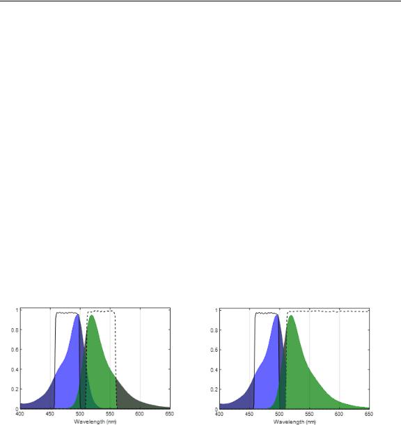
Filter Sets for Conventional vs. Multispectral Imaging
Filters used for conventional fluorescence imaging are often designed so they only transmit a very narrow range of wavelengths of light. Limiting the measurement to wavelength bands where the dye is inherently most responsive helps distinguish the desired dye from other dyes or background signals in the sample. In this way, it is possible to image several dyes, provided that their spectra are separated rather than overlapping. Based on the properties of common dyes, this puts an upper limit of ~4 on how many dyes can be imaged in any one sample.
An alternative approach is to image the sample multispectrally. In this case, a broad emission filter is used, and a tunable filter is engaged in the imaging path. The instrument takes pictures at several wavelengths within the emission band, so maps out the full shape of the dye response. This enables analysis software to identify what dye(s) are present, in what amounts, in each pixel, by spectral decomposition (“unmixing”). It also enables identifying, and removing, contributions from autofluorescence.
These two approaches are illustrated in Figure 4 and Figure 5.
Figure 4. Narrowband excitation (solid line) and emission (dashed line) filter for conventional imaging.
Figure 5. Narrowband excitation (solid line) and long-pass emission filter (dashed line) for multispectral imaging.
Ideally, the excitation filter would match the excitation maximum of the fluorescence label being used, and the emission filter would include the emission maximum. In practical terms, the filter maxima may be slightly different from the ideal case, due to limitations of filter manufacturing and because for many dyes the Stokes shift is small, so the maxima are quite close to one another.
P/N CLS147553 Rev. G |
Vectra Polaris User Manual |
PerkinElmer, Inc. |

Introduction 23
To image multiple dyes conventionally, one selects dyes that have very distinct excitation and/or emission response, and selects filters that are narrow enough to predominantly transmit the signal of only one dye at a time (Figure 6 and Figure 7).
Figure 6. Imaging four dyes by conventional fluorescence methods.
Figure 7. Seven dyes is too many to image by conventional methods.
This shows the emission spectra for four dyes (DAPI, FITC, Cy3, and Cy5.5) that are spectrally fairly distinct, and can be separated by conventional imaging. This works because there is only a little overlap between adjacent dyes. Excitation filters and dye response are omitted for clarity, but are similarly separable.
This approach breaks down when more dyes are present, or when it is important to account for the effects of autofluorescence. Figure 7 shows the spectra of 7 dyes, and with this many dyes there is no way to isolate their signals using conventional imaging techniques, or to account for autofluorescence.
P/N CLS147553 Rev. G |
Vectra Polaris User Manual |
PerkinElmer, Inc. |

Introduction 24
Multispectral Analysis
The Vectra Polaris imaging system offers a unique solution to the problem of separating the signals from highly multiplexed samples. Multispectral analysis is based on the fact that all fluorescent materials produce a unique spectral emission. If you excite a material and examine the emitted fluorescence over a range of wavelengths, the resulting emission intensities can generate an “emission spectrum”. This spectrum is different for each specific fluorescent material. For many fluorescent labels of biological interest, the emission spectra overlap, and may be further obscured by autofluorescence from the specimen. Multispectral imaging provides a way to distinguish between many overlapping emission spectra within the same area, overcoming the limitations of conventional filter-based imaging. With the additional information provided by the LCTF during MSI imaging the system can distinguish between dyes with fully overlapping spectra within a single channel (Figure 8).
P/N CLS147553 Rev. G |
Vectra Polaris User Manual |
PerkinElmer, Inc. |

Introduction 25
Figure 8. Unmixed multispectral image of human breast cancer tissue stained against CD4 (Green), CD20 (Red), CD8 (Yellow), FoxP3 (Orange), CD68 (Purple), Cytokeratin (Light Blue), and DAPI (Dark Blue) using Opal reagents.
P/N CLS147553 Rev. G |
Vectra Polaris User Manual |
PerkinElmer, Inc. |
Introduction 26
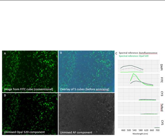
In general, multispectral analysis generates the spectral curves for the various fluorescent dyes or materials in a specimen. In addition, it generates a spectral curve for the autofluorescence that almost always is present to some degree. Using spectral analysis algorithms, the contribution of the individual fluorescence spectra are separated. The result is a set of images representing each spectrum that contributes to the final image 90 (Figure 9).
Figure 9. Removing auto-fluorescence with multispectral imaging. A) Conventional fluorescence image of tonsil tissue stained against CD4 with Opal 520 dye. B) Overlay of all 35 layers of a multispectral image acquired using five filter cubes. C) Emission spectra of pure autofluorescence (black line), pure Opal 520 (green line), and the mixture observed in 'B' (gray dashed line). The spectral references are used to 'unmix' the contribution of autofluorescence and Opal 520 at each pixel. D) Image of unmixed Opal 520 signal extracted from 'B' with > 10fold higher signal-to-background compared to 'A' because the autofluorescence contribution has been separated into the component image in 'E'.
P/N CLS147553 Rev. G |
Vectra Polaris User Manual |
PerkinElmer, Inc. |

Introduction 27
Whole Slide Scanning
Vectra Polaris scans slides using the following process:
1Color Overview:
Vectra Polaris takes a low power color overview of all four slides in each carrier, including the label for each slide. This initial step is performed regardless of whether you are using a fluorescence or brightfield protocol and is used to identify the presence of slides in the carrier and capture their labels.
2Coverslip Finding:
For each slide, Vectra Polaris will then find the coverslip using this overview scan. The coverslip defines the potential scan area.
For fluorescence protocols, you can further restrict this area by making a closed loop with a red, green, or blue Sharpie® marker. If closed-loop markup is present, the system will only scan within the loop. This is useful if your tissue is faintly stained, punctate, or if you have highly fluorescing non-tissue material (PAP pen, for example.)
For brightfield protocols, the coverslip will define the potential scan area. Closed-loop markup is not available for brightfield scans.
3Slide Height Finding:
Vectra Polaris engages specialized height-sensing optics to measure the top of the coverslip at up to 9 locations. This gives an initial focus estimate based on the expected coverslip thickness.
4Fluorescence Overview (Fluorescence protocols only):
If you are using a fluorescence protocol for this slide, Vectra Polaris will take another overview within the coverslip (or closed-loop markup), this time in fluorescence.
5Tissue Finding:
Using the corresponding overview, Vectra Polaris will automatically detect the sample on the slide. The resulting area will be scanned. If requested within the protocol, Vectra Polaris will scan the entire area within the coverslip (or closed-loop markup).
P/N CLS147553 Rev. G |
Vectra Polaris User Manual |
PerkinElmer, Inc. |

Introduction 28
6Focus Finding:
Vectra Polaris will measure focus at multiple points on the tissue to determine best focus. It uses the sample map from the previous step to choose the measurement grid, and continues until the grid is fully measured.
If the measured tissue height is irregular, Vectra Polaris increases the grid density and takes more readings until it finds the readings are regular at the newly finer scale.
All focus measurements include a dust-rejection algorithm, and an overall consistency check is applied as well, to further reduce the likelihood of dust-induced focus errors.
7Scanning:
Vectra Polaris then scans the slide.
Brightfield scans are conventional color scans that have been color and background corrected.
Fluorescence scans are multi-layered, with one layer for each filter you chose. To avoid photobleaching, the system uses a pulsed LED so the sample is only exposed to light during the time that the camera is taking a picture.
When scans are complete, they can be opened in Phenochart, the whole slide viewing application.
NOTES
Some dyes narrowly express in a single filter. Other dyes may express in multiple filters and may appear in more than one layer in a Vectra Polaris fluorescence scan. For example, Opal 570 will have signal in both Cy3 and TexasRed filters. If your sample is highly multiplexed, multiple dyes may appear in the same channel.
P/N CLS147553 Rev. G |
Vectra Polaris User Manual |
PerkinElmer, Inc. |

Introduction 29
Multispectral Imaging
Once Vectra Polaris has completed a whole slide scan of the tissue, individual regions can be selected for multispectral imaging.
Multispectral imagery is acquired using the following process:
1Selection of Multispectral Regions:
Regions for multispectral imaging are selected on a previously scanned slide. Using Phenochart, you can select individual fields or regions of interest. If desired, you can also select fields using a trained inForm algorithm. See the Phenochart documentation for more information.
When you configure that slide for MSI acquisition, Vectra Polaris will perform the following actions:
2Color Overview:
Vectra Polaris takes a low power color overview of all four slides in each carrier, including the label for each slide. This initial step is performed regardless of whether you are using a fluorescence or brightfield protocol and is used to identify the presence of slides in the carrier.
3Slide Registration:
Using the above overview along with the slide’s original overview, Vectra Polaris accounts for any shift or rotation of the slide to ensure that the multispectral region locations are accurate. The slide edges are used to account for any rotation or horizontal shift. The coverslip edges to account for vertical shifting.
4Slide Height Finding:
Vectra Polaris engages specialized height-sensing optics to measure the top of the coverslip at up to 9 locations. This gives an initial focus estimate based on the expected coverslip thickness.
5Acquisition of Multispectral Regions:
Vectra Polaris will then travel to each multispectral region site, autofocus, correct for exposure if requested, and acquire the multispectral image.
Multispectral imagery can then be viewed and analyzed in inForm.
P/N CLS147553 Rev. G |
Vectra Polaris User Manual |
PerkinElmer, Inc. |

Hardware Reference 30
Hardware Reference
This section identifies and describes the Vectra Polaris system hardware. It also lists the Vectra Polaris technical specifications.
WARNING
Lifting Hazard. Do not move the Vectra Polaris instrument. Installing, servicing, and moving the Vectra Polaris instrument should be performed only by qualified PerkinElmer service personnel. Contact PerkinElmer technical support if help is required (see page 7).
This section contains the following information:
•Front View hardware components
•Top View hardware components
•Right-Side View hardware components
•Left-Side Connectors
•Slide Carrier Hotel
•Slide Carrier
•Barcode Reader
•System Computer and Monitor
•Specifications
P/N CLS147553 Rev. G |
Vectra Polaris User Manual |
PerkinElmer, Inc. |
Loading...