


LabChip GX/GX II
User Manual
Copyright 2008-2014, PerkinElmer Health Sciences, Inc. All rights reserved. V4.2

Preface 2
Preface
Copyright
This manual is published by PerkinElmer Health Sciences, Inc., 68 Elm Street, Hopkinton, MA 01748 USA. Copyright 2008-2014, PerkinElmer Health Sciences, Inc and its parent, affiliated, and subsidiary companies. All rights reserved, including but not limited to those rights to reproduce this publication or parts thereof. Reproduction of this publication or parts thereof or the products it describes by any means or in any form is expressly prohibited without the written permission of PerkinElmer.
Trademarks
PerkinElmer, LabChip, the PerkinElmer logo, and the LabChip logo are registered trademarks of PerkinElmer Health Sciences, Inc and/or its parent, affiliates, and/or subsidiary companies (collectively “PerkinElmer”). Microsoft, Windows, and Windows NT are either registered trademarks or trademarks of Microsoft Corporation in the United States and/or other countries. All other trademarks and registered trademarks are the property of their respective holders.
Content
Any errors or omission which may have occurred in this publication, despite the utmost care taken in its production, will be corrected as soon as possible, but not necessarily immediately upon detection. PerkinElmer provides this publication “As Is” without warranty of any kind, either express or implied, including but not limited to the implied warranties of merchantability or fitness for a particular purpose. Some states or jurisdictions do not allow disclaimer of express or implied warranties in certain transactions; therefore, this statement may not apply to you. PerkinElmer reserves the right to revise this publication and to make changes from time to time in the content hereof without obligation of PerkinElmer to notify any person of such revision or changes. Further, PerkinElmer may make modifications to the product described in this manual at any time without any obligation to notify any person of such modifications.
Proper Equipment Operation
WARNINGS
•To reduce the risk of electric shock, do not remove the cover. No user serviceable parts inside. Refer to qualified service personnel if help is required.
•Use this product only in the manner described in this manual. If the equipment is used in a manner not specified by the manufacturer, the protection provided by the equipment may be impaired.
AVERTISSEMENTS
•Pour réduire le risque de choc électrique, ne pas retirer le couvercle. Ce produit ne contient aucune pièce pouvant être réparée par l’utilisateur. Au besoin, confier l’appareil à un réparateur qualifié.
•Ce produit ne doit être utilisé que comme décrit dans ce manuel. Si cet appareil est utilisé d’une manière autre que celle spécifiée par le fabricant, la protection fournie par l’appareil peut être entravée.
V4.2 |
LabChip GX User Manual |
PerkinElmer |

Preface 3
Contact Us
If you have a question about the LabChip GX that is not answered in this manual or online Help, or if you need assistance with this product, contact the PerkinElmer Technical Support Center:
Phone: (US Toll Free): 800-762-4000
(Worldwide): +1 203-925-4602 Fax: +1 203-944-4904
Email: global.techsupport@perkinelmer.com Internet: www.perkinelmer.com
For support outside the United States, contact your local PerkinElmer representative.
Before you call, you should have the following information available for the technical representative:
•Product serial number
•Software version (found by choosing About from the main Help menu)
•If applicable, the error number shown in the product software or in the log file.
Product Service and Customer Support Plans
PerkinElmer offers a full range of services to ensure your success. From our original factory warranty through a comprehensive line of customer support plans, PerkinElmer offers you Field Service Engineers and in-house Specialists who are dedicated to supporting your hardware, software and application development needs.
Call: |
(US Toll Free): 800-762-4000 |
|
(Worldwide): +1 203-925-4602 |
Fax: |
+1 203-944-4904 |
Email: |
global.techsupport@perkinelmer.com |
Our programs can include such useful services as:
•Preventive maintenance
•Diagnostic servicing performed on-site by PerkinElmer field service engineers or remotely via Technical Support
•Validation performed on-site by PerkinElmer field service engineers
•Extended use of the PerkinElmer Technical Support Center
•Software updates
•Parts, labor, and travel expense coverage
•Other customized services upon request
Training For Your Product
Contact the PerkinElmer Center for Training and Development for information about the availability of training courses for your product:
Call: (508) 497-2634
Fax: (508) 435-3439
V4.2 |
LabChip GX User Manual |
PerkinElmer |

Preface 4
FCC
This device complies with part 15 of the FCC (United States Federal Communications Commission) Rules. Operation is subject to the following two conditions:
•This device may not cause harmful interference, and
•This device must accept any interference received, including interference that may cause undesired operation.
CE
This device complies with all CE rules and requirements.
NOTE
Changes or modifications to this equipment not expressly approved by the party responsible for compliance could void the user’s authority to operate the equipment.
REMARQUE
Tout changement ou modification apporté à cet instrument non expressément approuvé par l’entité responsable de la conformité peut annuler l’autorisation d’opérer l’appareil accordée à l’utilisateur.
Table of Symbols
Table 1 contains symbols that identify particularly important information and alert you to the presence of hazards. These symbols may appear in this manual and/or on the product it describes.
Table 1. Important Symbols
Symbol Description
Symbole Description
DANGER: An imminently hazardous situation, which, if not avoided, will result in death or serious injury.
DANGER: Situation présentant un danger imminent qui, s’il n’est pas éliminé, peut entraîner des blessures graves, voire la mort.
WARNING: Caution, risk of danger. Refer to the User’s documentation.
AVERTISSEMENT: Attention, danger potentiel. Se reporter à la documentation de l’utilisateur.
NOTE: A cautionary statement; an operating tip or maintenance suggestion; may result in instrument damage if not followed.
REMARQUE: Énoncé indiquant une précaution à prendre, un conseil de fonctionnement ou une suggestion d’entretien; son non-respect peut provoquer des dommages à l’instrument.
V4.2 |
LabChip GX User Manual |
PerkinElmer |

Preface 5
Table 1. Important Symbols (Continued)
Symbol Description
Symbole Description
Hazardous voltage; risk of shock injury.
Tension dangereuse; risque de blessure par électrocution.
Crush hazard. Risk of body parts, hair, jewelry, or clothing getting caught in a moving part.
Danger d’écrasement. Faire attention que les parties corporelles, les cheveux, les bijoux ou les vêtements ne soient pas pris dans une pièce mobile.
Risk of puncture injury.
Risque de blessure par piqûre.
Risk of eye injury; wear safety glasses.
Risque de lésion oculaire; porter des lunettes de sécurité.
Risk of fire.
Risque d’incendie.
Risk of poison.
Risque d’empoisonnement.
Risk of explosion.
Risque d’explosion.
Hazardous fumes. Émanations dangereuses.
Laser light; avoid exposure. Risk of eye injury.
Rayonnement laser; éviter toute exposition. Risque de lésion oculaire.
Lifting hazard. May result in injury.
Levage dangereux. Peut entraîner des blessures.
Protective ground symbol.
Symbole de terre de protection.
Ground symbol.
Symbole de terre.
Fuse.
Fusible.
Alternating current.
Courant alternatif.
On (supply).
Marche (alimentation).
V4.2 |
LabChip GX User Manual |
PerkinElmer |

Preface |
6 |
Table 1. Important Symbols (Continued) |
||
|
|
|
Symbol |
Description |
|
Symbole |
Description |
|
|
|
|
|
Off (supply). |
|
|
Arrêt (alimentation). |
|
|
|
|
|
CE compliance mark. |
|
|
Marque de conformité CE. |
|
|
|
|
|
Signifies that the unit has passed safety tests for grounding, |
|
|
power line transience, and current leakage. |
|
|
Signifie que l’appareil a réussi les tests de sécurité pour la mise |
|
|
à la terre, le courant transitoire de ligne d’alimentation et la |
|
|
perte de courant. |
|
|
|
|
|
Input. |
|
|
Entrée. |
|
|
|
|
|
Output. |
|
|
Sortie. |
|
|
|
|
Equipment |
Yellow |
Caution, risk of danger |
labels are color |
Red |
Stop |
coded: |
Blue |
Mandatory action |
Les étiquettes |
Green Safe condition or information |
|
de l’appareil |
Jaune |
Attention, danger potentiel |
sont codées |
Rouge |
Arrêter |
couleur: |
Bleu |
Intervention obligatoire |
|
Vert |
Condition sûre ou informations de sécurité |
|
|
|
|
Helpful hints, additional information |
|
|
Conseils utiles, informations supplémentaires |
|
|
|
|
V4.2 |
LabChip GX User Manual |
PerkinElmer |

Instrument Safety |
7 |
Instrument Safety
The following safety information about the LabChip GX is included in this documentation. Read and review all safety information before operating the LabChip GX.
•Required Training
•“Chemical Safety” on page 8
•“Laser Safety” on page 9
•“Electrical Safety” on page 10
•“Mechanical Safety” on page 11
Required Training
Ensure that all personnel involved with the operation of the instrument have:
•Received instruction in general safety practices for laboratories.
•Received instruction in specific safety practices for the instrument.
•Read and understood all related MSDSs.
WARNING
Use this product only in the manner described in this manual. If the equipment is used in a manner not specified by the manufacturer, the protection provided by the equipment may be impaired.
V4.2 |
LabChip GX User Manual |
PerkinElmer |

Instrument Safety |
8 |
Chemical Safety
WARNING
Some chemicals used with the LabChip GX are potentially hazardous and can cause illness.
•Read and understand the material safety data sheet (MSDS) provided by the chemical manufacturer before you store, handle, or work with any chemical or hazardous material.
•Minimize contact with and inhalation of chemicals and chemical wastes. Wear appropriate personal protective equipment when handling chemicals (e.g., safety glasses, gloves, or clothing).
For additional safety guidelines consult the MSDS.
•Do not leave chemical containers open. Use only with adequate ventilation, including a fume hood, if necessary.
•Check regularly for chemical leaks or spills. If a leak or spill occurs, follow the manufacturer’s cleanup procedures as recommended on the MSDS.
•Dispose of waste in accordance with good laboratory practices and local, state/provincial, or national environmental and health regulations.
•After emptying waste containers, seal them appropriately.
•Comply with all local, state/provincial, or national laws and regulations related to chemical storage, handling, and disposal.
V4.2 |
LabChip GX User Manual |
PerkinElmer |

Instrument Safety |
9 |
Laser Safety
WARNING
BRIGHT LIGHT HAZARD. LabChip GX Instruments contain Class 3B laser diodes. The LabChip GX is classified as a Class 1 device because the lasers are appropriately enclosed (embedded) and indicated with Warning labels.
Complies with 21 CFR 1040.10 except for deviations pursuant to Laser Notice 50, dated June 24, 2007.
Complies with IEC 60825-1: 1993, A1: 1997, A2: 2001.
Class 1
Laser
Product
635 nm (visible red) laser source, 10 mW maximum continuous (CW)
WARNING
•Use of controls or adjustments or performance of procedures other than those specified herein may result in hazardous radiation exposure.
•NEVER remove back, side, or front panels of the instrument while the laser is powered. Panels (which, if removed, could lead to laser exposure) are marked with the labels shown below:
•These panels are intended to be removed for service only by qualified personnel; they are not intended to be removed during operation or for maintenance by users. The only removable maintenance panel is the lower panel at the back of the instrument, which can be removed to access the back of the robot, if cleaning is necessary.
V4.2 |
LabChip GX User Manual |
PerkinElmer |
Instrument Safety 10
Electrical Safety
The LabChip GX is powered by a UL/CSA/VDE approved 100-240 VAC, 50/60 Hz input, 5, 15, 24 VDC output power supply. Additionally, the LabChip GX High Voltage circuitry is currentlimited to non-hazardous levels. Users should observe the following:
WARNING
Do not open the instrument enclosure. There are no user serviceable parts inside.
The wall outlet or the power cable connector on the back of the instrument should be accessible after the system's installation, to enable trained service personnel to safely disconnect power from the system during servicing.
The computer supplied with the LabChip GX instrument has internal lithium batteries. Batteries should not be incinerated.
WARNING
Danger of explosion if battery is incorrectly replaced. Replace only with the same or equivalent type recommended by the manufacturer's instructions.
Power Cord Selection
United States and Canada
The LabChip GX instrument is shipped with a NEMA 5-15 / IEC 320 power cord. If the power cord needs to be replaced, substitute power cords must be UL Listed, Type SJT or equivalent, minimum No. 18 AWG, 3-conductor with ground conductor that for safety considerations should never be disconnected or defeated. The cord’s plug to the wall must be a three-pin grounding type connector with a NEMA 5-15P (15A, 125V) plug configuration. The cord’s connector at the unit must conform to requirements for an EN 60 320/IEC 320 Standard Sheet C13 connector.
The equipment is intended to be plugged into a standard NEMA 5- 15R receptacle in the wall.
V4.2 |
LabChip GX User Manual |
PerkinElmer |
Instrument Safety 11
International
All power cord sets must be approved by an acceptable, accredited agency responsible for evaluation in the country where the power cord set and system will be used.
The flexible cord must be <HAR> Type H05VV-F, 3-conductor, minimum 0.75 - 1 mm2 conductor size (230 volt input). Power cord set fittings that is, the appliance coupler and wall plug, must bear the certification mark of the agency responsible for evaluation in the country where it will be used. The appliance coupler must meet the mechanical configuration of an EN 60 320/IEC 320 Standard Sheet C13 connector for mating with appliance inlet on the system.
Fuses
The LabChip GX instruments do not contain any user replaceable fuses. Contact PerkinElmer Technical Support (see “Contact Us” on page 3) if blown fuses are suspected.
Mechanical Safety
The LabChip GX instruments have a three axis robot that moves quickly and can be a pinch hazard. Keep the front door of the instrument closed when the robot is moving. Keep hands away from the robot when not actually placing microplates in the instrument or changing the ladder and buffer vials. Robot access areas are marked with the following warning label:
V4.2 |
LabChip GX User Manual |
PerkinElmer |

Table of Contents |
12 |
Table of Contents |
|
Preface .................................................................................................................... |
2 |
Instrument Safety ................................................................................................... |
7 |
Required Training................................................................................................ |
7 |
Chemical Safety .................................................................................................. |
8 |
Laser Safety ........................................................................................................ |
9 |
Electrical Safety ................................................................................................ |
10 |
Power Cord Selection .................................................................................. |
10 |
Fuses .......................................................................................................... |
11 |
Mechanical Safety ............................................................................................. |
11 |
Introduction........................................................................................................... |
18 |
Principles of Operation ...................................................................................... |
19 |
Software Modes Available ................................................................................. |
21 |
Operation .............................................................................................................. |
22 |
Opening the LabChip GX Software.................................................................... |
23 |
Creating Desktop Shortcuts............................................................................... |
23 |
Creating a New Assay ....................................................................................... |
24 |
Running an Assay ............................................................................................. |
25 |
Select the Auto Export Settings ......................................................................... |
29 |
Monitoring the Run ............................................................................................ |
30 |
Stopping a Run ................................................................................................. |
31 |
Continuing a Stopped Run ................................................................................ |
32 |
Saving Data Files .............................................................................................. |
33 |
Saving Workspace Files .................................................................................... |
34 |
Selecting Wells using a Sample Names File ...................................................... |
35 |
Using a Barcode to Specify the Sample Names File .................................... |
36 |
Adding a New Plate ........................................................................................... |
38 |
Placing the Barcode on the Plate ...................................................................... |
40 |
Calibrating the Optics ........................................................................................ |
41 |
Data Analysis ........................................................................................................ |
42 |
How the Software Analyzes DNA Data .............................................................. |
43 |
How the Software Analyzes Protein Data .......................................................... |
45 |
How the Software Analyzes RNA Data .............................................................. |
49 |
How the Software Analyzes Glycan Data........................................................... |
54 |
How the Software Analyzes Protein Charge Variant Data .................................. |
57 |
How the Software Analyzes Genomic DNA Data ............................................... |
58 |
Organizing, Retrieving, and Backing Up Data Files ........................................... |
59 |
Opening a New Workspace ............................................................................... |
59 |
Opening a Data File .......................................................................................... |
60 |
Adding a Collection to a Workspace .................................................................. |
61 |
Selecting the Wells in a Collection .................................................................... |
62 |
Using Sample Names Files ............................................................................... |
63 |
Create a Sample Name File ......................................................................... |
63 |
V4.2 |
LabChip GX User Manual |
PerkinElmer |

Table of Contents |
13 |
Sample Name File Format (.CSV Format).................................................... |
65 |
Applying Different Window Values to Expected Peaks of the Same Size in |
|
Different Wells ............................................................................................. |
66 |
Sample Name File Import Errors .................................................................. |
66 |
Using Expected Fragments/ Expected Proteins/ Expected Glycans ................... |
67 |
Entering EFs, EPs, or EGs in the Assay Analysis Window ........................... |
67 |
Exporting EFs, EPs, or EGs ......................................................................... |
68 |
Importing EFs, EPs, or EGs ......................................................................... |
68 |
Forcing Expected Peaks .............................................................................. |
69 |
Viewing the EFs/EPs/EGs in the Graph View ............................................... |
69 |
Viewing the EFs/EPs/EGs in the Gel View ................................................... |
70 |
Viewing the EFs/EPs/EGs in the Well Table ................................................ |
71 |
Viewing the EFs/EPs/EGs in the Peak Table ............................................... |
71 |
Modifying Analysis Parameters ......................................................................... |
72 |
Changing the Peak Find Parameters ........................................................... |
73 |
Adding a Peak ............................................................................................. |
74 |
Excluding a Peak ......................................................................................... |
74 |
Splitting a Peak............................................................................................ |
75 |
Merging Two Peaks ..................................................................................... |
75 |
Adjusting the Peak Baseline ........................................................................ |
76 |
Setting the Baseline for a Range of Peaks ................................................... |
76 |
Removing a Manual Baseline....................................................................... |
77 |
Selecting a Default Ladder........................................................................... |
77 |
Using the Default Ladder for Alignment........................................................ |
79 |
Exporting the Default Ladder in an Assay .................................................... |
79 |
Clearing the Default Ladder in a Plate ......................................................... |
79 |
Changing the Time Window for Analysis ...................................................... |
80 |
Aligning or Unaligning the Marker Peaks ..................................................... |
80 |
Saving and Exporting Assays ............................................................................ |
84 |
Changing the View of the Data .......................................................................... |
85 |
Viewing Gels ............................................................................................... |
85 |
Viewing Zero Baselines .............................................................................. |
86 |
Adjust Pane Widths ..................................................................................... |
87 |
Show or Hide Views..................................................................................... |
87 |
Zoom In and Zoom Out ................................................................................ |
88 |
Viewing Graphs in the Overlay Electropherograms Tab ............................... |
89 |
Viewing Graphs in the Electropherograms Tab ............................................ |
90 |
Viewing Analysis Errors and Warnings......................................................... |
92 |
Viewing Multiple Properties in the Well Table View ...................................... |
93 |
Copying Information .......................................................................................... |
94 |
Reanalyzing a Data File .................................................................................... |
95 |
Printing Workspace Information......................................................................... |
96 |
Exporting Data ................................................................................................ |
102 |
Exporting Data Manually ............................................................................ |
105 |
Using the GX Software to Analyze GX Touch Data ........................................... |
107 |
Understanding Peak Finding.............................................................................. |
108 |
V4.2 |
LabChip GX User Manual |
PerkinElmer |

Table of Contents |
14 |
Data Smoothing .............................................................................................. |
108 |
Peak Detection - Slope Threshold ................................................................... |
109 |
Peak Splitting - Inflection Threshold ................................................................ |
112 |
Peak Identification........................................................................................... |
113 |
Software Security ............................................................................................... |
114 |
Locking and Unlocking the Software................................................................ |
116 |
Managing User Accounts ................................................................................ |
117 |
Adding New Users ..................................................................................... |
118 |
Changing User Information ........................................................................ |
119 |
Printing User Information ........................................................................... |
120 |
Activating and Deactivating User Accounts ................................................ |
120 |
Changing Access Rights ............................................................................ |
121 |
Printing Access Rights ............................................................................... |
122 |
Setting Policies for User Accounts ............................................................. |
123 |
Printing User Policies................................................................................. |
124 |
Electronic Signatures ...................................................................................... |
125 |
Automatically Exporting Copies of Data Files .................................................. |
126 |
Reverting to a Specific Data File Revision ....................................................... |
126 |
Audit Trail........................................................................................................ |
127 |
Viewing the Audit Trail ............................................................................... |
128 |
Exporting the Audit Trail ............................................................................ |
129 |
Central Data Repository (CDR) ....................................................................... |
130 |
CDR Security Suggestions......................................................................... |
130 |
Creating New Data Folders ........................................................................ |
131 |
Moving Data Files into Folders................................................................... |
131 |
Deleting Data Folders ................................................................................ |
131 |
Hiding Data Files in the CDR Manager Window ......................................... |
132 |
Showing Hidden Data Files in the CDR Manager Window.......................... |
132 |
Remote CDR Server Backup ........................................................................... |
133 |
Setting Up the Remote CDR Server ........................................................... |
133 |
Backing Up Data Files to the Remote CDR ................................................ |
135 |
Restoring Data Files from the Remote CDR............................................... |
136 |
Viewing the Files in the Remote CDR Folder ............................................. |
137 |
Manually Backing Up and Restoring the CFR Files.......................................... |
138 |
Backing Up CFR Files................................................................................ |
138 |
Restoring CFR Files .................................................................................. |
140 |
Software Reference ............................................................................................ |
142 |
LabChip GX Main Window............................................................................... |
143 |
Menu Bar ................................................................................................... |
144 |
Chip Status and Run Status ....................................................................... |
151 |
Error Message Area................................................................................... |
153 |
Plate View or Plate List .............................................................................. |
154 |
Collection Pane ......................................................................................... |
157 |
Graph View................................................................................................ |
158 |
Graph View Properties ............................................................................... |
164 |
Gel View .................................................................................................... |
167 |
V4.2 |
LabChip GX User Manual |
PerkinElmer |

Table of Contents |
15 |
Gel View Properties ................................................................................... |
170 |
Well Table View ......................................................................................... |
172 |
Peak Table View........................................................................................ |
174 |
Peak Table Properties ............................................................................... |
179 |
Filter View ................................................................................................. |
180 |
About LabChip GX Window ............................................................................. |
183 |
Add New Expected Peak Window.................................................................... |
184 |
Add Plate Window ........................................................................................... |
185 |
Assay Analysis Window................................................................................... |
186 |
Assay Information Tab ............................................................................... |
187 |
Alignment Tab ........................................................................................... |
188 |
Analysis Tab .............................................................................................. |
189 |
Peak Find Tab ........................................................................................... |
192 |
Expected Fragments/Proteins/Glycans Tab ............................................... |
196 |
Excluded Peaks Tab .................................................................................. |
198 |
Smear Analysis Tab................................................................................... |
200 |
Titer Tab .................................................................................................... |
202 |
Advanced Tab ........................................................................................... |
205 |
Audit Trail Window .......................................................................................... |
208 |
Audit Trail Export Window ............................................................................... |
209 |
Audit Trail Manage Columns Window .............................................................. |
210 |
CDR Manager Window .................................................................................... |
211 |
CDR Server Utility Window.............................................................................. |
213 |
CDR Utility Window ......................................................................................... |
214 |
Change Password Window.............................................................................. |
216 |
Data File Version Window ............................................................................... |
217 |
Event Viewer Window ..................................................................................... |
218 |
Export Window ................................................................................................ |
219 |
Installation Qualification Window ..................................................................... |
222 |
Layout Options Window................................................................................... |
223 |
Login Window.................................................................................................. |
224 |
New Collection Window ................................................................................... |
225 |
Optics Calibration Window .............................................................................. |
226 |
Perform Signature Window.............................................................................. |
228 |
Plate Information Window................................................................................ |
229 |
Print Window ................................................................................................... |
230 |
Print Validation Reports Window ..................................................................... |
232 |
Rename Collection Window............................................................................. |
233 |
Robot Teaching Wizard ................................................................................... |
234 |
Welcome Window ...................................................................................... |
235 |
Teach Robot Window................................................................................. |
236 |
Teach the X, Y and Z Reference Positions Window ................................... |
237 |
Verify a Plate Window................................................................................ |
238 |
Verify Positions Window ............................................................................ |
239 |
Finished Window ....................................................................................... |
240 |
Verify All Target Positions Window ............................................................ |
241 |
Verify All Target Positions Correct Window ................................................ |
242 |
V4.2 |
LabChip GX User Manual |
PerkinElmer |

Table of Contents |
16 |
Run File Editor Window ................................................................................... |
243 |
Run Info Window ............................................................................................. |
244 |
Sample Name Editor Window .......................................................................... |
245 |
Save Workspace As Window........................................................................... |
247 |
Select a Data File Window .............................................................................. |
248 |
Start Run Window ........................................................................................... |
249 |
Run Tab..................................................................................................... |
250 |
Output Tab ................................................................................................ |
252 |
Advanced Tab ........................................................................................... |
254 |
System Diagnostics Window ........................................................................... |
256 |
Unlock Application Window ............................................................................. |
258 |
Unlock Data File Window ................................................................................ |
259 |
User Administration Window............................................................................ |
260 |
Create New User ....................................................................................... |
261 |
Edit Users .................................................................................................. |
263 |
Show User Info .......................................................................................... |
264 |
De/Activate User........................................................................................ |
266 |
Define Access............................................................................................ |
267 |
Set Policies................................................................................................ |
269 |
LabChip GX Instrument Description .................................................................. |
270 |
Front View....................................................................................................... |
270 |
Front Panel ..................................................................................................... |
271 |
Rear Connectors ............................................................................................. |
272 |
Optics ............................................................................................................. |
273 |
Chip Pressure System..................................................................................... |
273 |
Barcode Reader .............................................................................................. |
273 |
DNA, RNA, and Protein Chips ......................................................................... |
274 |
Chip Cartridge ................................................................................................. |
275 |
High Voltage Interface ............................................................................... |
276 |
Microplate Carrier............................................................................................ |
277 |
USB Key for 21 CFR Part 11 Option................................................................ |
277 |
Specifications .................................................................................................. |
278 |
General ..................................................................................................... |
278 |
Environmental ........................................................................................... |
278 |
Electrical.................................................................................................... |
278 |
Assay Voltage ........................................................................................... |
279 |
Chip Pressure............................................................................................ |
279 |
Chip Temperature Control ......................................................................... |
279 |
Fluorescence Detection ............................................................................. |
279 |
Light Source (Red laser diode) .................................................................. |
279 |
Barcode Reader ........................................................................................ |
279 |
Maintenance and Service ................................................................................... |
280 |
Cleaning the Chip Cartridge ............................................................................ |
281 |
Cleaning the Instrument Electrodes................................................................. |
281 |
Cleaning Test Chip C ...................................................................................... |
282 |
Troubleshooting and Diagnostics...................................................................... |
283 |
V4.2 |
LabChip GX User Manual |
PerkinElmer |

Table of Contents |
17 |
Searching for Events in the Events Tab........................................................... |
283 |
Viewing Current Events in the Events Tab....................................................... |
284 |
Viewing Past Events in the Events Tab ........................................................... |
284 |
Error Messages ............................................................................................... |
285 |
Device <Name> is Disconnected ............................................................... |
286 |
Plate Carrier Motion Blocked ..................................................................... |
286 |
Home Timeout ........................................................................................... |
286 |
Move Timeout ............................................................................................ |
287 |
Pressure Leak Detected ............................................................................ |
287 |
Focus Failed .............................................................................................. |
287 |
Maximum Samples Exceeded .................................................................... |
288 |
Chip Primed for Different Assay ................................................................. |
288 |
HV Check Failed ........................................................................................ |
288 |
Current Leakage Check Failed .................................................................. |
289 |
Chip Temperature Warning ........................................................................ |
289 |
Running Installation Qualification (IQ) ............................................................. |
290 |
Running Operational Qualification (OQ) .......................................................... |
290 |
Diagnostics ..................................................................................................... |
291 |
Running the Diagnostics Tests .................................................................. |
291 |
Description of Diagnostic Tests.................................................................. |
292 |
Troubleshooting Assay Problems .................................................................... |
298 |
Software Problems .......................................................................................... |
298 |
Cannot Save a File .................................................................................... |
298 |
Computer Software Lock-Ups .................................................................... |
299 |
Zipping the Log Files ....................................................................................... |
300 |
Tips and Shortcuts ............................................................................................. |
301 |
Glossary of Terms .............................................................................................. |
302 |
PerkinElmer Product Warranty .......................................................................... |
330 |
PerkinElmer Software License Agreement ........................................................ |
332 |
Index .................................................................................................................... |
336 |
V4.2 |
LabChip GX User Manual |
PerkinElmer |

Introduction 18
Introduction
This manual includes general instructions for using the LabChip GX hardware and software. It includes general procedures for operating the system, analyzing the data, using software security to comply with 21 CFR Part 11 requirements, instrument maintenance, and hardware and software troubleshooting.
DNA, gDNA, RNA, Protein, Glycan, and Protein Charge Variant (CZE) Chip and Reagent Kits are available to run specific assays on the LabChip GX. The Assay Kits include the reagents and consumables required to run the specific assay. Protein, Glycan, and Protein Charge Variant assays are only supported on LabChip GX II instruments.
Assay User Guides
Assay User Guides provide information about the assay. Instructions for preparing the chip, the plate, the ladder vial, and the buffer vial are included in the LabChip GX/GXII Assay User Guide for the specific assay that you are running. Detailed information about the assays, including Specifications, Safety Warnings, Preparation Procedures, Expected Results, Troubleshooting, LabChip Kit Essential Practices, and Reordering Information is also located in the LabChip GX/GXII Assay User Guide for the specific assay that you are running.
The current version of the Assay User Guides can be accessed on the PerkinElmer web site at:
www.perkinelmer.com/labchipguides.
Assay Quick Guides
Assay Quick Guides are included with each Assay Kit and include instructions for preparing the chip to run an assay.
The current version of the Assay Quick Guides can be accessed on the PerkinElmer web site at:
www.perkinelmer.com/labchipguides.
V4.2 |
LabChip GX User Manual |
PerkinElmer |
Introduction 19
Principles of Operation
The LabChip GX assays are based on traditional gel electrophoresis principles that have been transferred to a chip format. The chip format dramatically reduces separation time and provides automated sizing and quantitation information in a digital format.
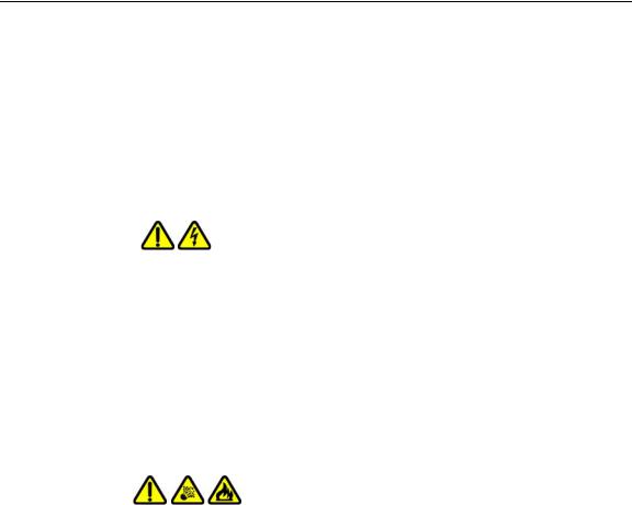
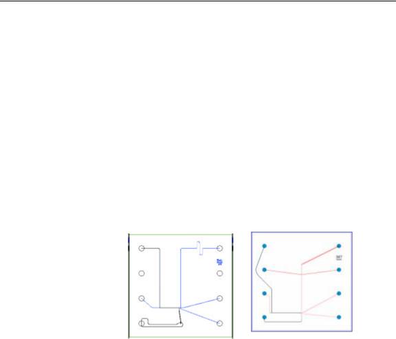
The chip contains an interconnected set of microchannels that join the separation channel and buffer wells. One of the microchannels is connected to a short capillary that extends from the bottom of the chip at a 90-degree angle. The capillary sips sample from the wells of a microplate during the assay.
Some of the channels in the chip are larger than others. The larger channels contain buffer. During the chip preparation, the smaller channels and some of the wells are filled with sieving gel and buffer.
Figure 1. DNA/RNA Chip and Protein Chip Schematics
After the channels are filled, the chip functions as an integrated electrical circuit. The circuit is driven by the 7 electrodes in the electrode cartridge that contact solutions in the chip's wells when the chip holder is closed. Each electrode is connected to an independent power supply that provides maximum control and flexibility.
The polymer filling the smaller channels in the chip is designed to sieve DNA/RNA fragments or proteins by size as they are driven through it by means of electrophoresis, similar to using agarose or polyacrylamide gels. The sample and sieving buffers also contain a fluorescent dye that gets brighter upon binding to double-stranded DNA, RNA, or protein/SDS complex. (Protein, Glycan, and Protein Charge Variant assays are only supported on LabChip GX II instruments.)
V4.2 |
LabChip GX User Manual |
PerkinElmer |

Introduction 20
Principles of Operation (Continued)
In the chip, each sample is sipped from the microplate by negative pressure until a sufficient quantity is loaded in the chip. The sample is then moved electrophoretically into the central channel. As the fragments move down the central channel, they separate by size, and then pass the laser, which excites the fluorescent dye bound to the molecule. The LabChip GX software plots fluorescence intensity versus time and produces electropherograms for each sample (see Figure 2).
Figure 2. Electropherogram
The data can be viewed in a gel-like format on the Gel Tab to achieve the appearance of a slab gel. (The colors of the gel can be changed.)
Figure 3. Gel View
V4.2 |
LabChip GX User Manual |
PerkinElmer |
Introduction 21
Principles of Operation (Continued)
For DNA, RNA, Protein, and Glycan assays, quantitating the concentration and accurately sizing each fragment are achieved by comparing against a sizing ladder and running internal standards or “markers” with each sample. Internal standards of known concentration are mixed with the sample to aid in quantitation.
The amount of sample sipped into the chip depends on pH, salt concentration, and buffer additives. The internal standards normalize these factors so that the software can use the ratio of the area of the curve of the standard to the unknown peak to determine concentration directly. The internal standards lie slightly outside the assay range so they do not interfere with analysis.
Capillary Zone Electrophoresis (CZE) is an electrophoretic separation technique used to evaluate the charge heterogeneity of proteins in a sample. For Protein Charge Variant assays, analytes are separated based on their net charges, with molecules with a higher net charge migrating faster than those with a lower net charge. The data is analyzed to calculate the % Relative Amount of the peaks.
Software Modes Available
The LabChip GX software has three modes available: Instrument, Simulation, and Reviewer. The mode can be selected when the LabChip GX software is installed.
Instrument Mode is used to control the LabChip GX instrument and to review data generated by the LabChip GX.
•The 21 CFR Part 11 Compliance option is a purchased option that can be used when the software is installed in Instrument mode.
Simulation Mode is used to simulate running an instrument and to review data generated by the LabChip GX.
Reviewer Mode is used to review data and develop assays, but does not control an instrument or display the instrument controls.
If the LabChip GX software is installed in Instrument mode, shortcuts can be created on the desktop to run the LabChip GX software in Simulation or Reviewer mode (see “Creating Desktop Shortcuts” on page 23).
V4.2 |
LabChip GX User Manual |
PerkinElmer |

Operation 22
Operation
This section includes general instructions for using the LabChip GX hardware and software to run an assay.
This section contains the following information:
•Opening the LabChip GX Software
•Creating Desktop Shortcuts
•Creating a New Assay
•Running an Assay
•Select the Auto Export Settings
•Monitoring the Run
•Stopping a Run
•Continuing a Stopped Run
•Saving Data Files
•Saving Workspace Files
•Selecting Wells using a Sample Names File
•Adding a New Plate
•Placing the Barcode on the Plate
•Calibrating the Optics
For assay-specific information, see the LabChip GX/GXII Assay User Guide for the specific assay that you are running. For instructions on preparing the chip and plate, see the LabChip GX/GXII Assay Quick Guide for the specific assay. The current version of the Assay User Guides and Quick Guides can be accessed on the PerkinElmer web site at: http://www.perkinelmer.com/labchipguides.
To run an assay in the LabChip GX:
1Open the LabChip GX software. (See “Opening the LabChip GX Software” on page 23.)
2If necessary, create a new assay. (See “Creating a New Assay” on page 24)
3Clean the electrodes and the O-Rings as directed in the
LabChip GX/GXII Assay User Guide.
4If necessary, calibrate the optics (see page 41) and run Diagnostics (see page 291).
5Prepare the chip for the assay as directed in the LabChip GX/GXII Assay Quick Guide.
V4.2 |
LabChip GX User Manual |
PerkinElmer |

Operation 23
6Prepare the plate for the assay as directed in the LabChip GX/GXII Assay Quick Guide. (See “Placing the Barcode on the Plate” on page 40 if using barcodes on the sample plates.)
7Run the assay. (See “Running an Assay” on page 25.)
Opening the LabChip GX Software
If the LabChip GX software was installed in Instrument mode, with or without the 21 CFR Part 11 security option, the desktop icon opens the software in Instrument mode. If desired, you can create shortcuts for Reviewer mode or Simulation mode as described below. If the LabChip GX software was installed in Reviewer mode, the desktop icon opens the software in Reviewer mode.
To open the LabChip GX software:
1Double-click on the LabChip GX icon on the Windows desktop.
2If 21 CFR Part 11Security is installed, the Login Window opens. Type a valid LabChip GX user name and password into the text boxes and click the OK button. (For instructions on creating LabChip GX user names, see “Adding New Users” on
page 118.)
The LabChip GX Main Window opens.
3See “Creating a New Assay” on page 24 or “Running an Assay” on page 25.
Creating Desktop Shortcuts
If the LabChip GX software was installed in Instrument mode, you can create desktop shortcuts to run the LabChip GX software in Reviewer mode or Simulation Mode, if desired.
To create new software shortcuts on the Windows desktop:
1Right-click on the LabChip GX icon on the Windows desktop and click Copy.
2Right-click on the Windows desktop and click Paste. A copy of the LabChip GX icon is created on the desktop.
3Rename the icon as desired.
4Right-click on the new icon and click Properties.
5On the Shortcut tab, enter the following in the Target text box:
V4.2 |
LabChip GX User Manual |
PerkinElmer |

Operation 24
•For Reviewer mode: "C:\Program Files\Caliper Life Sciences\LabChip GX\LabChip.exe" /review
•For Simulation mode: "C:\Program Files\Caliper Life Sciences\LabChip GX\LabChip.exe" /simulate
6 Click OK in the Properties window.
Creating a New Assay
The LabChip GX software enables you to create a new assay by opening and editing an existing assay and then saving the assay with a new name.
To create a new assay:
1On the LabChip GX Main Window, select Tools Assay Editor. The Select Assay To Edit window opens.
2Select the name of the Assay file that you want to edit and click the OK button. The Assay Analysis Window opens and displays the settings for the open assay.
3Modify the settings as necessary for the new assay. (See Modifying Analysis Parameters or Reanalyzing a Data File for information on setting or changing analysis parameters.)
4Click the Save Assay button at the bottom of the Assay Analysis window, specify the desired name for the new assay file, and click the Save button.
V4.2 |
LabChip GX User Manual |
PerkinElmer |

Operation 25
Running an Assay
If a new chip has been inserted in the instrument, the chip is automatically primed at the start of the first run. Since priming is a lengthy process, you can start priming the chip before you are ready to start the run. (To save time, the sample plate can be prepared while the chip is priming.)
To prime a chip before starting the run:
1Select Instrument Start Prime to start priming for a specific assay.
2Select the assay in the Choose Assay for Chip Prime window and then click the OK button. (If the chip is not primed before starting the run, the chip is primed automatically when you click the Run button.)
To start an assay to read a plate:
1Click the Run button on the LabChip GX Main Window (see page 143) to open the Start Run Window.
If the maximum number of samples for the chip have already been run or if the chip was last primed for a different assay, a message displays instructions for resolving the problem.
2Click the Run tab in the Start Run window.
3Select the type of assay you want to run in the Assay Type drop-down list. (Protein, Glycan, and Protein Charge Variant assays are only supported on LabChip GX II instruments.)
4Type the operator's name in the Operator Name text box.
5Select the name of the plate in the Plate Name drop-down list. To use a plate that is not listed in the Plate Name list, see “Adding a New Plate” on page 38.
6To read the plate barcode, select the Use Barcode check box. (The plate barcode can be used to name the data file if selected.)
V4.2 |
LabChip GX User Manual |
PerkinElmer |

Operation 26
Running an Assay (Continued)
7On the Plate diagram, select the wells to be sampled.
•To select all wells and ladders on the plate, click the doublearrow button in the lower-right corner of the plate.
•To select all rows on the plate, click the double-arrow button at the top left corner of the plate.
•To select all columns on the plate, click the double-down- arrow button at the top right corner of the plate.
•To select a single column, click the column number at the top or bottom of the plate.
•To select or clear all wells in a quadrant, click the Q1, Q2, Q3, or Q4 button.
•To select a single row, click the row letter on the left or right side of the plate.
•Clear specific wells by clicking on a selected well.
•To use a Sample Names file to select the wells, see “Selecting Wells using a Sample Names File” on page 35.
8Select the desired sipping order for the selected wells, Rowwise, Column-wise, or File Order.
9Click the Output Tab in the Start Run window.
10To change the Data Path, either type the desired path or click the Browse button and select the desired location for the data files. Clicking the Default button restores the default data path.
NOTE
Data files should be saved to a local folder on the computer's hard drive. Saving data files to a network drive may cause loss of data if the network connection is slow or interrupted.
11If desired, select the Create Daily Sub-Directory check box to create a new sub-directory for data files each day.
12If the 21 CFR Part 11 option is installed and you want to save a copy of the data files to a folder outside of the CDR or if the 21 CFR Part 11 option is not installed and you want to save a second copy of the data files, see “Automatically Exporting Copies of Data Files” on page 126.
V4.2 |
LabChip GX User Manual |
PerkinElmer |

Operation 27
Running an Assay (Continued)
13To add the File Prefix, Computer Name, Project Name,
Barcode, Date, and/or Time to the data file name, select or clear the desired check boxes or type the desired file prefix and project name. The file name components are added to the data file name in the order in which they are selected. Leave the text box blank to omit the File Prefix or Project Name from the file name.
14To automatically export data tables, graphs, or gels, select the
Automatic Export check box, click the Auto Export Settings button, and then select the desired Auto Export settings (see page 29).
15Click the Advanced Tab in the Start Run window.
16To perform the assay multiple times on the same plate, select the desired number of times to run the assay in the Plate Cycles text box.
17To randomly sample a specific percent of the selected wells, select the Random Selection check box and specify the percent of wells to sample during the run.
18To repeatedly run the selected wells and combine the data into one data file, select the Sample Saver check box and select the number of times to repeatedly run the selected wells in the Repeats text box.
19To use a file to supply the sample names, click the Browse button next to Sample Names File, select the name of the .csv file that contains the sample names, and click the Open button. The path and name of the file displays in the text box.
To use a Sample Names file to select the wells, see “Selecting Wells using a Sample Names File” on page 35.
20To use a file to supply the Expected Peaks, click the Browse button next to Expected Peaks File, select the name of the
.gep file that contains the expected peaks, and click the Open button. The path and name of the file displays in the text box. (See “Using Expected Fragments/ Expected Proteins/ Expected Glycans” on page 67 for more information.)
21To use a file to supply the Excluded Peaks, click the Browse button next to Excluded Peaks File, select the name of the
.gep file that contains the excluded peaks, and click the Open button. The path and name of the file displays in the text box.
V4.2 |
LabChip GX User Manual |
PerkinElmer |

Operation 28
22Click the Start button to start the assay. A new workspace opens to display the data.
See “Monitoring the Run” on page 30 for information about viewing data during the run.
V4.2 |
LabChip GX User Manual |
PerkinElmer |

Operation 29
Select the Auto Export Settings
The Auto Export settings specify which views to automatically export at the end of each run and specifies the format for each view. Click the Auto Export Settings button in the Output Tab on the Start Run Window to open the Export Window.
To select the desired views to export:
1Select the check boxes next to the views to export. Selecting Export All selects all check boxes.
2For each selected view, to change the location for the files, click the Browse (...) button and select the desired location.
If the default path is selected, the path displays in blue. If the path is not the default path, the path displays in purple. To set the path to the default, right-click on the path and select Reset to Default.
3If Raw Data is selected, click the AIA Format check box to export in Chromatography Data Interchange Format or clear the check box to export in CSV format. If CSV is selected:
•Select Include Size Data to align the data to the well's ladder (for one file per well) or to the first well (for a single data file) and include the size data in the exported data. (Not available for CZE assays.)
•Select Export Single Table to export the data for all wells in the plate to one CSV file. If not selected, the data from each well is exported to a separate CSV file.
4If Gel is selected:
a Select either Single File to include gels for all wells in the run in the same image file, or select Separate Files to export each gel to a separate image file.
b To adjust the contrast minimum and maximum values for all gels to a specific lane in the gel, choose the desired well in the Contrast Lane drop-down list. (Only available after the sample wells have been selected on the Run tab.)
c If desired, change the height, in pixels, of the exported gel graphics in the Height text box.
5If either Electropherogram or Gel is selected, choose the desired format for the image files.
6Click OK to save the Export settings. The specified files are exported at the end of the run.
V4.2 |
LabChip GX User Manual |
PerkinElmer |

Operation 30
Monitoring the Run
The following occurs after a run is started in the LabChip GX software:
1The priming and warming steps are performed.
•The priming step fills the channels of the chip with reagent. (Only performed if the chip holder has been opened since the last run.)
•The warming step allows the heater plate located in the chip holder to regulate chip temperature to 30°C.
•Data collection begins after the warming and priming steps are completed.
2After the run begins, the Start button on the LabChip GX main window changes to Stop.
3The Active Data Tab displays the electropherogram of the well currently being read. Data is saved to a file with the name shown above the plate diagram after each well is completed.
4To view the results for individual wells as data is acquired or after the run is finished, click a well in the Plate View or Plate List, a sample name in the Well Table View, or a lane in the Gel View. Data from the selected well displays in the Overlay Electropherograms Tab and the Peak Table View.
For more information on data analysis, see “Data Analysis” on page 42.
5To stop the run before it is complete, see Stopping a Run.
6When the assay is complete, Run Successful displays in the Status line.
7If desired, remove the plate and/or remove the chip.
To save the analyzed data:
1Select File Save Workspace. The Save Workspace As Window opens with the default workspace name as the name of the data file.
2If desired, change the location and/or the name of the workspace file and click the Save button. (Workspace files have a .gxw file extension.)
To view or re-analyze the data, see Data Analysis.
V4.2 |
LabChip GX User Manual |
PerkinElmer |
 Loading...