


 Loading...
THERMAL ANALYSIS
TGA 4000
Installation and Hardware
Guide
Release History
Part Number |
Release |
Publication Date |
|
|
|
09931396 |
C |
January 2018 |
|
|
|
Any comments about the documentation for this product should be addressed to:
User Assistance
PerkinElmer, Inc.
710 Bridgeport Avenue
Shelton, Connecticut 06484-4794
U.S.A.
Or contact: http://www.perkinelmer.com/contactus/
Notices
The information contained in this help file is subject to change without notice.
Except as specifically set forth in its terms and conditions of sale, PerkinElmer makes no warranty of any kind with regard to this help file, including, but not limited to, the implied warranties of merchantability and fitness for a particular purpose.
PerkinElmer shall not be liable for errors contained herein for incidental consequential damages in connection with furnishing, performance or use of this material.
Copyright Information
This help file contains proprietary information that is protected by copyright.
All rights are reserved. No part of this file may be reproduced in any form whatsoever or translated into any language without the prior, written permission of PerkinElmer, Inc.
Copyright © 2018 PerkinElmer, Inc.
Trademarks
Registered names, trademarks, etc. used in this help file, even when not specifically marked as such, are protected by law.
PerkinElmer is a registered trademark of PerkinElmer, Inc.
Pyris is a trademark of PerkinElmer, Inc.
Microsoft and Windows are registered trademarks of Microsoft Corporation in the United States and other countries.

Contents |
|
Introduction............................................................................................... |
5 |
Pyris Installation ............................................................................................... |
6 |
Safety and Regulatory Information........................................................... |
7 |
Symbols Used in Online Help ............................................................................. |
8 |
Notes, Cautions and Warnings..................................................................... |
8 |
Symbols Used on the Instruments..................................................................... |
11 |
Electrical Warnings........................................................................................... |
12 |
Electromagnetic Compatibility (EMC) ................................................................. |
14 |
Europe...................................................................................................... |
14 |
South Korea .............................................................................................. |
14 |
United States (FCC) ................................................................................... |
14 |
Electrical Safety ............................................................................................... |
15 |
Pollution Degree 2 ..................................................................................... |
15 |
WEEE Instructions for PerkinElmer Products ...................................................... |
16 |
Prepare the Laboratory............................................................................ |
17 |
Prepare the Laboratory..................................................................................... |
18 |
Electrical Requirements.............................................................................. |
18 |
Environmental Requirements...................................................................... |
18 |
Purge Gas and Pneumatic Supply ............................................................... |
19 |
Space Requirements .................................................................................. |
19 |
Install Multiple Analyzers ........................................................................ |
21 |
Install Multiple Analyzers .................................................................................. |
22 |
Install a TGA 4000 ................................................................................... |
25 |
Safety Precautions for the TGA 4000 ................................................................. |
26 |
Important Specifications ............................................................................ |
28 |
Decontamination and Cleaning.......................................................................... |
29 |
Decontamination ....................................................................................... |
29 |
Cleaning the Instrument ............................................................................ |
29 |
General Laboratory Safety.......................................................................... |
29 |
TGA 4000 Warning Labels................................................................................. |
30 |
Warning Labels on the Upper Ring Around the Furnace................................ |
30 |
Warning Labels on the Back of the TGA 4000.............................................. |
32 |
Install a TGA 4000 ........................................................................................... |
34 |
Unpack the TGA 4000....................................................................................... |
35 |
Parts Included ........................................................................................... |
36 |
Set Up the TGA 4000 System Components......................................................... |
38 |
Select the Correct Voltage.......................................................................... |
38 |
Connect the Purge Gas Supply to the TGA 4000 .......................................... |
40 |
Connect the Purge Gas and System Purge Gas Lines to the TGA 4000 .......... |
41 |
Connect the Cooling Device to the TGA 4000 .............................................. |
41 |
Level the TGA 4000 ................................................................................... |
45 |
Connect the TGA 4000 System Components ...................................................... |
46 |
Configure the TGA 4000 ................................................................................... |
48 |
Starting the Pyris Manager ......................................................................... |
49 |
Calibrate the TGA 4000 .................................................................................... |
50 |
Furnace Calibration.................................................................................... |
50 |
Temperature Calibration ............................................................................ |
51 |
Weight Calibration ..................................................................................... |
53 |
TGA 4000 Hardware................................................................................. |
55 |
TGA 4000 Thermogravimetric Analyzer.............................................................. |
56 |
Features of the TGA 4000................................................................................. |
57 |
Heating..................................................................................................... |
58 |
Sample Handling ............................................................................................. |
59 |
Sample Preparation................................................................................... |
59 |
Sample Pans............................................................................................. |
59 |
Sample Atmosphere .................................................................................. |
59 |
Loading the Sample into the TGA 4000....................................................... |
60 |
Calibration....................................................................................................... |
61 |
Maintenance.................................................................................................... |
62 |
Cleaning the Furnace and Sample Holder.................................................... |
62 |
Cleaning the Cover.................................................................................... |
62 |
Changing the Sample Thermocouple .......................................................... |
63 |
TGA 4000 Part Numbers................................................................................... |
65 |
Miscellaneous Part Numbers ...................................................................... |
66 |
AS 8000 Autosampler............................................................................... |
67 |
AS 8000 Autosampler....................................................................................... |
68 |
Safety Precautions for the AS 8000................................................................... |
70 |
How the AS 8000 Autosampler Works ............................................................... |
71 |
Autosampler Work Cycle............................................................................ |
71 |
Reduced Time Cycle.................................................................................. |
73 |
AS 8000 Autosampler Gripper Alignment........................................................... |
74 |
AS 8000 Sample Handling ................................................................................ |
75 |
Sample Preparation................................................................................... |
75 |
Sample Pans............................................................................................. |
75 |
Sample Loading ........................................................................................ |
75 |
Running a Play List with the AS 8000................................................................ |
78 |
Troubleshooting .............................................................................................. |
82 |
Error Messages from the TGA 4000............................................................ |
85 |
AS 8000 Autosampler Maintenance ................................................................... |
86 |
Cleaning and Decontamination................................................................... |
86 |
Replace the Sample Thermocouple in a TGA 4000, Pyris 6 TGA or STA 6000 |
|
with AS 8000 Autosampler ............................................................................... |
87 |
Introduction

6 . TGA 4000 Installation and Hardware Guide
Pyris Installation
NOTE: If you are going to install multiple analyzers, or just want to install a universal serial bus, see Install Multiple Analyzers before you begin to install an analyzer.
This user’s guide gives information on the installation of your PerkinElmer Thermal Analysis System, and details about the operation and maintenance of the hardware. This information can also be found in the Pyris Installation and Hardware Help provided with your Pyris software.
Information on the operation of the Pyris software can be found in the software Help.
In general, the installation procedure consists of the following steps:
•Prepare the laboratory
•Unpack the thermal analysis system
•Set up the required system components (for example, purge gases, cooling supply, and analyzer-specific items)
•Connect the system components
•Configure the analyzer
•Calibrate the analyzer
Safety and Regulatory
Information

8 . TGA 4000 Installation and Hardware Guide
Symbols Used in Online Help
The Pyris help files contain information and warnings that must be followed by the user to ensure safe operation and to maintain the instrument(s) in a safe condition.
Possible hazards that could harm the user or result in damage to the instrument are clearly stated at appropriate places throughout Help.
All eight-digit numbers are PerkinElmer part numbers unless stated otherwise.
Notes, Cautions and Warnings
Three terms, in the following standard formats, are also used to highlight special circumstances and warnings.
NOTE: A note indicates additional, significant information that is provided with some procedures.
Safety and Regulatory Information . 9
We use the term CAUTION to inform you about situations that could CAUTION result in serious damage to the instrument or other equipment. Details
about these circumstances are in a box like this one.
Caution (Achtung)
Bedeutet, daß die genannte Anleitung genau befolgt werden muß, um einen Geräteschaden zu vermeiden.
Caution (Bemærk)
Dette betyder, at den nævnte vejledning skal overholdes nøje for at undgå en beskadigelse af apparatet.
Caution (Advertencia)
Utilizamos el término CAUTION (ADVERTENCIA) para advertir sobre situaciones que pueden provocar averías graves en este equipo o en otros. En los recuadros como éste se proporciona información sobre este tipo de circunstancias.
Caution (Attention)
Nous utilisons le terme CAUTION (ATTENTION) pour signaler les situations susceptibles de provoquer de graves détériorations de l'instrument ou d'autre matériel. Les détails sur ces circonstances figurent dans un encadré semblable à celui-ci.
Caution (Attenzione)
Con il termine CAUTION (ATTENZIONE) vengono segnalate situazioni che potrebbero arrecare gravi danni allo strumento o ad altra apparecchiatura. Troverete informazioni su tali circostanze in un riquadro come questo.
Caution (Opgelet)
Betekent dat de genoemde handleiding nauwkeurig moet worden opgevolgd, om beschadiging van het instrument te voorkomen.
Caution (Atenção)
Significa que a instrução referida tem de ser respeitada para evitar a danificação do aparelho.

10 . TGA 4000 Installation and Hardware Guide
We use the term WARNING to inform you about situations that could result in personal injury to yourself or other persons. Details about these circumstances are in a box like this one.
WARNING
Warning (Warnung)
Bedeutet, daß es bei Nichtbeachten der genannten Anweisung zu einer Verletzung des Benutzers kommen kann.
Warning (Advarsel)
Betyder, at brugeren kan blive kvæstet, hvis anvisningen ikke overholdes.
Warning (Peligro)
Utilizamos el término WARNING (PELIGRO) para informarle sobre situaciones que pueden provocar daños personales a usted o a otras personas. En los recuadros como éste se proporciona información sobre este tipo de circunstancias.
Warning (Danger)
Nous utilisons la formule WARNING (DANGER) pour avertir des situations pouvant occasionner des dommages corporels à l'utilisateur ou à d'autres personnes. Les détails sur ces circonstances sont données dans un encadré semblable à celui-ci.
Warning (Pericolo)
Con il termine WARNING (PERICOLO) vengono segnalate situazioni che potrebbero provocare incidenti alle persone. Troverete informazioni su tali circostanze in un riquadro come questo.
Warning (Waarschuwing)
Betekent dat, wanneer de genoemde aanwijzing niet in acht wordt genomen, dit kan leiden tot verwondingen van de gebruiker.
Warning (Aviso)
Significa que a não observância da instrução referida poderá causar um ferimento ao usuário.

Safety and Regulatory Information . 11
Symbols Used on the Instruments
Caution, hot surface.
Attention surface chaude.
Caution, risk of electric shock.
Attention, risque d'électrocution.
Caution
Documentation must be consulted to determine
the nature of the potential hazard and any actions which have to be taken.
Attention
La documentation doit être consultée pour déterminer
La nature du risque potentiel et des actions qui doit être pris.
Caution – Cold surface
Attention, Surface froide
The following additional graphic symbols used on the instrument:
Indicates alternating current
Indicates the primary protective grounding terminal
Indicates the off position of the main power switch
Indicates the on position of the main power switch
12 . TGA 4000 Installation and Hardware Guide
Electrical Warnings
WARNING
AVERTISSEMENT
Connect the instrument to an AC line power outlet that has a protective ground connection. To ensure satisfactory and safe operation of the instrument, it is essential that the protective ground conductor (the green/yellow lead) of the line power cord is connected to true electrical ground. Any interruption of the protective ground conductor, inside or outside the instrument, or disconnection of the protective ground terminal may impair the protection provided by the instrument.
Connectez l'instrument à une prise de courant de ligne AC qui a une connexion de terre de protection. Pour assurer un fonctionnement satisfaisant et sécurisé de l'instrument, il est essentiel que le conducteur de terre de protection (le fil vert / jaune) du cordon d'alimentation de la ligne soit connecté à une vraie terre électrique. Toute interruption du conducteur de terre de protection, à l'intérieur ou à l'extérieur de l'instrument, ou la déconnexion de la borne de terre de protection peut nuire à la protection fournie par l'instrument.
Do not operate the instrument with any covers or parts removed.
WARNING
Ne pas utiliser l'instrument avec des couvertures ou des pièces retirees.
AVERTISSEMENT
WARNING
AVERTISSEMENT
Do not attempt to make adjustments, replacements, or repairs to this instrument except as described in this help file. Only a PerkinElmer service representative should be permitted to service the instrument.
N'essayez pas de faire des ajustements, des remplacements ou des réparations à cet instrument, sauf comme décrit dans ce fichier d'aide. Seul un représentant du service PerkinElmer devrait être autorisé à servir l'instrument.

Safety and Regulatory Information . 13
Use only fuses with the required current rating and of the specified type for replacement.
WARNING
N'utilisez que des fusibles avec la note de courant requise et du type spécifié pour le remplacement.
AVERTISSEMENT

14 . TGA 4000 Installation and Hardware Guide
Electromagnetic Compatibility (EMC)
Europe
All information concerning EMC standards is in the Declaration of Conformity, and these standards may change as the European Union adds new requirements.
PerkinElmer instruments have been designed and manufactured, having regard to the state of the art, to ensure that:
•the electromagnetic disturbance generated does not exceed the level above which radio and telecommunications equipment or other equipment cannot operate as intended;
•it has a level of immunity to the electromagnetic disturbance to be expected in its intended use which allows it to operate without unacceptable degradation of its intended use.
South Korea
This device complies with MSIP (Ministry 0f Science, ICT, and Future Planning) EMC Registration requirements. This instrument is registered as a Class B instrument for residential and/or buiness use.
B ( )
(B ) ,.
United States (FCC)
This equipment has been tested and found to comply with the limits for a Class B digital device, pursuant to part 15 of the FCC Rules. These limits are designed to provide reasonable protection against harmful interference when the equipment is operated in a commercial environment. This equipment generates, uses, and can radiate radio frequency energy and, if not installed and used in accordance with the instruction manual, may cause harmful interference to radio communications. Operation of this equipment in a residential environment may cause harmful interference in which the user will be required to correct the interference at their own expense.
NOTE: Changes or modifications not expressly approved by PerkinElmer could cause the instrument to violate FCC (U.S. Federal Communications Commission) emission regulations, and because of this violation could void the user’s authority to operate this equipment.

Safety and Regulatory Information . 15
Electrical Safety
This analyzer conforms to IEC publication 61010-1 (“Safety requirements for electrical equipment for measurement, control and laboratory use”) as it applies to IEC Class 1 (earthed) appliances, and therefore meets the requirements of the Low Voltage Directive 2006/95/EC.
Pollution Degree 2
This product will operate safely in environments that contain nonconductive foreign matter up to Pollution Degree 2 in EN/IEC 61010-1.
Normally only non-conductive POLLUTION occurs. Occasionally, however, a temporary conductivity caused by condensation must be expected.

16 . TGA 4000 Installation and Hardware Guide
WEEE Instructions for PerkinElmer Products
or
A label with a crossed-out wheeled bin symbol and a rectangular bar indicates that the product is covered by the Waste Electrical and Electronic Equipment (WEEE) Directive and is not to be disposed of as unsorted municipal waste. Any products marked with this symbol must be collected separately, according to the regulatory guidelines in your area.
The objectives of this program are to preserve, protect and improve the quality of the environment, protect human health, and utilize natural resources prudently Requirements for waste collection, reuse, recycling, and recovery programs vary by regulatory authority at your location. Contact your local responsible body (for example, your laboratory manager) or authorized representative for information regarding applicable disposal regulations. Contact PerkinElmer at the web site listed below for information specific to PerkinElmer products.
Web address:
www.perkinelmer.com/WEEE
For Customer Care telephone numbers select “Contact us” on the web page.
Products from other manufacturers may also form a part of your PerkinElmer system. These other producers are directly responsible for the collection and processing of their own waste products under the terms of the WEEE Directive. Please contact these producers directly before discarding any of their products.
Consult the PerkinElmer web site (above) for producer names and web addresses.
Prepare the Laboratory

18 . TGA 4000 Installation and Hardware Guide
Prepare the Laboratory
The following sections describe requirements for your Thermal Analysis System. Make sure your laboratory meets all of the requirements before you try to install the system. You should step through the topics in the order presented below.
Before starting installation, please read the Safety and Regulatory Information.
•Electrical Requirements
•Environmental Requirements
•Purge Gas and Pneumatic Supply Requirements
•Space Requirements
Electrical Requirements
Power Source
An independent power source should be provided for the system, including the computer. The power source should not be associated with heavy-duty equipment such as large motors, or with possible sources of high-frequency interference such as photocopying systems, discharge lamps, or radio transmitters. The power supply should be fused at a maximum of 20 A (120 V systems) or 16 A (200–240 V systems).
Line Voltage
PerkinElmer analyzers and their associated instruments are designed to operate within a line voltage range of 10% of the nameplate voltage or other such voltage selected at installation to suit the particular country or region. (The range for 240 V systems is +6%, –10%.) The supply must be smooth, clean, earthed and free of transient voltages over 40 V.
The frequency range is ±1% for 50 Hz and 60 Hz systems.
Instrument Maximum Power Requirements
Refer to the Safety Precautions for the instrument.
Environmental Requirements
You must provide the following laboratory conditions for your Thermal Analysis System:
•A clean area, free from vibration and strong magnetic fields.
•An adequate and stable power source for all system components.
•The area must have a relative humidity of 20–75% (without condensation).
•For optimum performance, the temperature of the area should be between 10 °C and 35 °C (50 °F and 95 °F).
•The instrument will operate safely between 5 °C and 40 °C.
•Place the system components in an area that is not in direct sunlight or direct contact with heating and cooling ducts or units.

Prepare the Laboratory . 19
•The instruments are for indoor use only.
•The storage temperature is between 20 °C and 60 °C.
•The altitude limitation for the operation of this instrument is 2000 m.
•The altitude for storage of this instrument is 0–12000 m.
•The installation overvoltage category for all instruments is Category II.
•The pollution degree is 2 for all instruments. (This product will operate safely in environments that contain nonconductive foreign matter up to Pollution Degree 2 in EN/IEC 61010-1.)
•The instrument must be positioned so that the appliance coupler can be removed to completely disconnect the power from the instrument.
NOTE: If the equipment is used in a manner not specified by PerkinElmer, the protection provided by the equipment may be impaired.
Purge Gas and Pneumatic Supply
The recommended purge gas for all Thermal Analyzers at ambient temperatures is argon or nitrogen with a minimum purity of 99.9%. Other gases, such as air or oxygen, may also be used. Air or oxygen is recommended for the purge gas when performing oxidation studies (DSC analyses).
The purge gas for any instrument must be dry. Use a size 1 A cylinder equipped with a pressure regulator that has a shutoff valve at the outlet. The shutoff valve should have 1/4-in. NPT male threads on the outlet side for connection to the analyzer’s purge gas line.
Space Requirements
Refer to the Safety Precautions for the instrument.
Once all of the above requirements are met, you can install your analyzer.

20 . TGA 4000 Installation and Hardware Guide
Install Multiple Analyzers
22 . TGA 4000 Installation and Hardware Guide
Install Multiple Analyzers
The only way to attach multiple instruments to your computer is via a universal serial bus. PerkinElmer no longer supports the Multiport RS-232 Card (P/N 0940-2018). Installation of the universal serial bus MUST be done before installing any analyzer.
A Pyris Series USB Multiport is an RS-232 module that uses the USB port on the PC and features plug-and-play intelligent connectivity. The USBs supported by PerkinElmer are the EdgePort/4 (P/N 0940-2020) and EdgePort/8 (P/N 0940-2019). They eliminate the need to install cards into dedicated computer slots and reconfigure the system. Computers with standard USB allow peripherals to be automatically configured as soon as they are physically attached without the need to reboot or run setup.
NOTE: Some PerkinElmer analyzers now have USB ports in addition to, or sometimes in place of, RS-232 ports. If you are working with these analyzers, you will need to use a USB hub device instead of the Edgeport to connect multiple analyzers to a single computer. A suitable 7-port USB hub is available (P/N HH10151008). Contact your PerkinElmer Service Representative for further information.
To install an EdgePort:
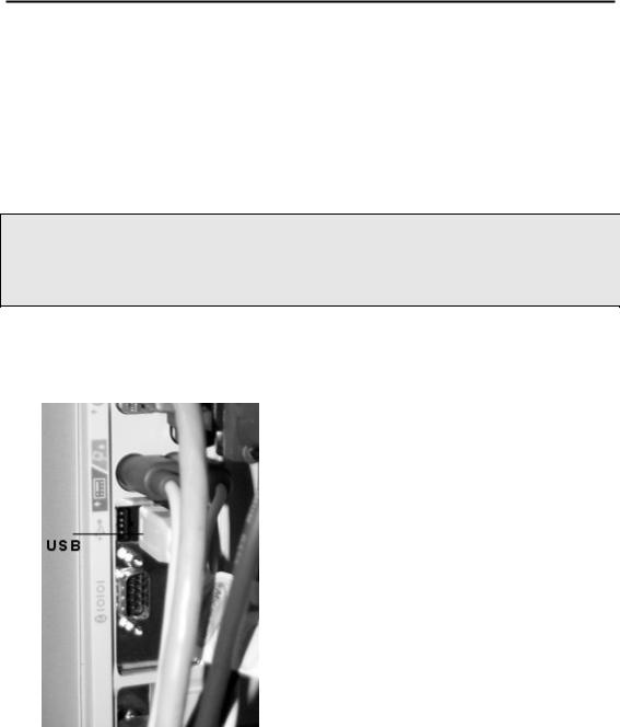
1.Attach one end of the USB cable to one of the USB connectors at the back of the computer.
Install Multiple Analyzers . 23
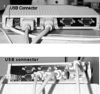
2.Attach the other end of the connector cable to the USB port on the EdgePort.
EdgePort/4
EdgePort/8
DO NOT connect any instruments to the EdgePort at this time.
If your computer is connected to the Internet, it will now download the software drivers for the EdgePort. Once this process is completed, you can install the individual analyzers by connecting them to the RS-232 ports on the EdgePort and configuring them in the Pyris software.

24 . TGA 4000 Installation and Hardware Guide
Install a TGA 4000
26 . TGA 4000 Installation and Hardware Guide
Safety Precautions for the TGA 4000
WARNING
AVERTISSEMENT
Be sure that all instrument operators read and understand the following precautions. It is advisable to post a copy of these precautions on or near the instrument itself.
Assurez-vous que tous les opérateurs d'instruments lisent et comprennent les précautions suivantes. Il est conseillé de publier une copie de ces précautions sur ou près de l'instrument lui-même.
The following precautions must be observed when using the TGA 4000:
•Never switch off the computer until it has completed its normal shutdown procedure.
•Never press the Reset button on the computer if the Pyris software appears to malfunction. Press the CTRL–ALT–DEL keys simultaneously and select Task Manager. From the Task Manager, close the Pyris software.
•Never remove the outer instrument cover of the TGA 4000 without shutting the instrument down and disconnecting its power cord from the power source.
•Before connecting the TGA 4000 to the power outlet, check the voltage setting and fuse.
•The TGA 4000 requires a good earth ground that is common to the earth ground of the computer.
•Do not disconnect cables or tubes from the TGA 4000 while the instrument is on.
•Never open the furnace when it is at a high temperature.
•Always observe the proper startup and shutdown procedures with the TGA 4000 and all related instruments.
•Do not operate the instrument in a cold room. The ambient temperature and the temperature of the instrument should be between 10 °C and 30 °C.
•Use proper lifting posture when lifting the analyzer. The TGA 4000 with autosampler weighs 19 kg. Lift the autosampler from underneath. Never attempt to lift the analyzer by the autosampler (if installed) or by any cables attached.
•When cleaning the instrument, consult PerkinElmer if there is any doubt about the compatibility of decontamination or cleaning agents with parts of the equipment or with material contained in it.
Install a TGA 4000 . 27
To remove the furnace lid, always use tw eezers; the furnace might be hot.
WARNING
Pour retirer le couvercle du four, utilisez toujours une pince à épiler; le four pourrait être chaud.
AVERTISSEMENT
Do not touch the inside of the furnace; it might be hot and internal pollution can cause loss of performance.
WARNING
Ne pas toucher l'intérieur du four; il pourrait être chaud et
la pollution interne peut entraîner une perte de
performance.
AVERTISSEMENT
Always ensure that there is adequate ventilation when
operating the TGA 4000. Operate the TGA 4000 in a fume
hood.
WARNING
Assurez-vous toujours qu'il existe une ventilation adéquate
lorsque vous utilisez le TGA 4000. Faites fonctionner le TGA AVERTISSEMENT 4000 dans une hotte aspirante.
CAUTION
ATTENTION
Do not expose the sample holder to mechanical stress. If no external cooling is applied, do not operate the TGA 4000 above 50 °C.
Ne pas exposer le support de l'échantillon aux contraintes mécaniques. Si aucun refroidissement externe n'est appliqué, ne pas utiliser le TGA 4000 au-dessus de 50 ° C.
Loading...