

Page 1
09931297D
Lambda 465 Fiber Optic Probe Installation Instructions
Contac ting PerkinElmer
Introduction
Features
This instruction sheet describes the installation of this accessory which is used with the Lambda 465
Spectrophotometer.
NOTE:
Read these instructions before you install this accessory.
Supplies, replacement parts, and accessories can be ordered directly from PerkinElmer, using the part
numbers.
See our website:
http://perkinelmer.com
PerkinElmer's catalog service offers a full selection of high-quality supplies.
To place an order for supplies and many replacement parts, request a free catalog, or ask for information:
If you are located within the U.S., call toll free 1-800-762-4002, 8 a.m. to 8 p.m. EST. Your order will be
shipped promptly, usually within 24 hours.
If you are located outside of the U.S., call your local PerkinElmer sales or service office.
The probes provide a convenient way of performing absorption or transmission measurements by dipping
or inserting the probe end into the medium or environment. This accessory is especially useful for
embedding into process streams for real-time, on-line sample monitoring.
• Easy to install
• Dip Probe for measuring liquid samples without using a cell
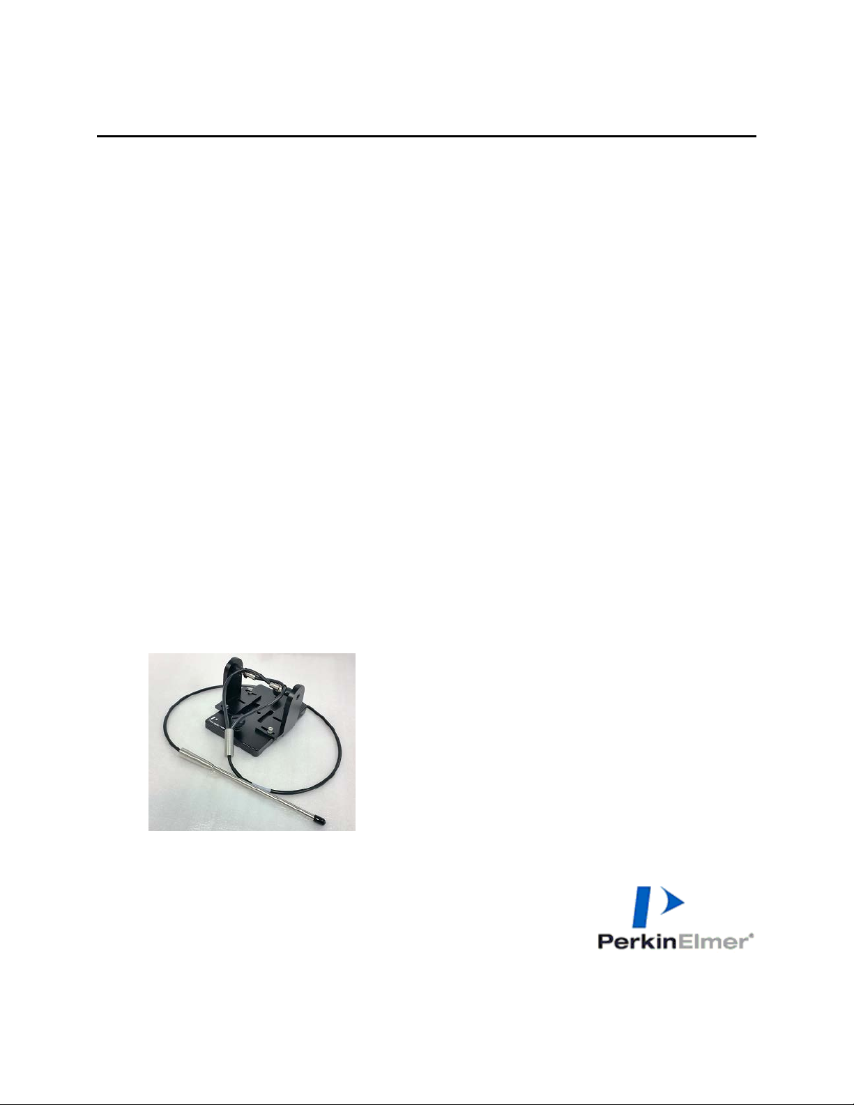
Figure 1 Lambda 465 Fiber Optic Probe [P/N: N4104012]
with Fiber Optic Probe [Part No: N4101048]
PerkinElmer, 710 Bridgeport Avenue,
Shelton, CT 06484-4794, U.S.A
Produced in the USA.
Page 2

2
Dimensions and Sp ec i fi ca tio ns
Description
Configuration of the Fiber Optic Probe
Physical Characteristic Specification
A: Fiber Type Fused Silica
09931297D
B: Fiber Size
C: Connector SMA 905
D: PVC Jacket
Fiber Optic Probe
Fiber Coupling Mount
E: Path Length 10 mm
Spectral Range 200 nm ~ 1100 nm
Overall Length (OAL) 100 ~ 120 cm
Breakout Length (BOL) 18 ~ 23cm
Probe Length (PL) 15.2 cm
Dimension (mm)
Weight (Kg)
600 µm
∅ 0.19’’ OD
150(W) X 100(H) X 84(L)
0.75
Figure 2 Lambda 465 Fiber Optic Probe include Fiber Coupling mount
Page 3

3
Installation
1. Disassemble the existing cell holder.
09931297D
Figure 3 Location of the two knob bolts
2. Install the fiber optic probe by fastening the knob bolts.
Figure 4 Installing the fiber Optic probe
3. Connect the communication cable and the power cord, and then turn on the power of the Lambda
465.
Page 4
4
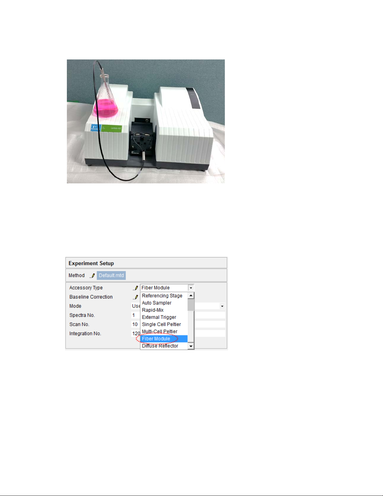
4. Place the probe into the liquid sample.
Measurement
Figure 5 Placing the probe in the liquid
09931297D
NOTE:
Start the sample measurement after warming up at least 20 minutes.
1. Launch the UV Lab software.
2. Choose the Fiber Module in the Accessory Type.
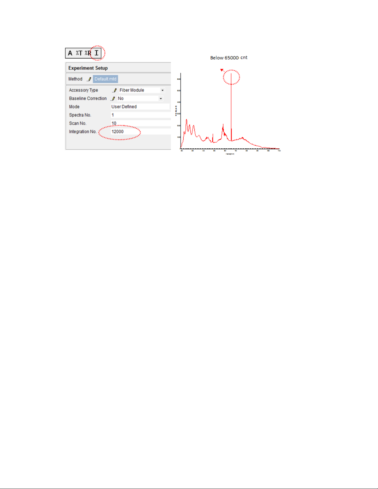
3. After dipping the probe into the blank solution, select the intensity mode, and then click Blank. By
changing the Integration no. up to 30000, adjust the D2 peak intensity not to be saturated in the
spectrum as shown in the picture below.
Page 5
5
4. Select the Absorbance mode and measure blank and sample.
Troubleshooting
When the Intensity value is lo w
Before measurement, make sure that bubble does not exist at the mirror side of the probe.
5. Clean the probe with D.I water after the measurement.
09931297D
1. Make sure that bubble does not exist at the mirror side of the probe.
If bubbles existed, the intensity of the light is low due to scattering of bubbles. You should remove
the bubbles completely and perform measuring.
2. Increase the Integration Number in the UV Lab Software
You should increase the Integration Number since the intensity of the light which passes through the
fiber is somewhat weak.
3. Check the condition of the fiber optic probe
Check if the lens placed inside the fiber optic probe is contaminated.
Remove the contaminant with alcohol.
Page 6

09931297D
6
 Loading...