

PerkinElmer Lambda 365 Fiber Coupling Module, Lambda 365 Fiber Optic Probe Installation Instructions Manual
Page 1
09931262E
Lambda 365 Fiber Co upling Module and Fiber Optic Probe
Installati on Instruc t io ns
Contac ting PerkinEl mer
Features
This instruction sheet describes the installation of this accessory which is used with the Lambda 365
Spectrophotometer.
NOTE:
Read these instructions before you install this accessory.
Supplies, replacement parts, and accessories can be ordered directly from PerkinElmer, using the part
numbers.
See our website:
http://perkinelmer.com
PerkinElmer's catalog service offers a full selection of high-quality supplies.
To place an order for supplies and many replacement parts, request a free catalog, or ask for information:
If you are located within the U.S., call toll free 1-800-762-4002, 8 a.m. to 8 p.m. EST. Your order will be
shipped promptly, usually within 24 hours.
If you are located outside of the U.S., call your local PerkinElmer sales or service office.
• Durable stainless steel design
• Dip Probe for measuring liquid samples without using a cell
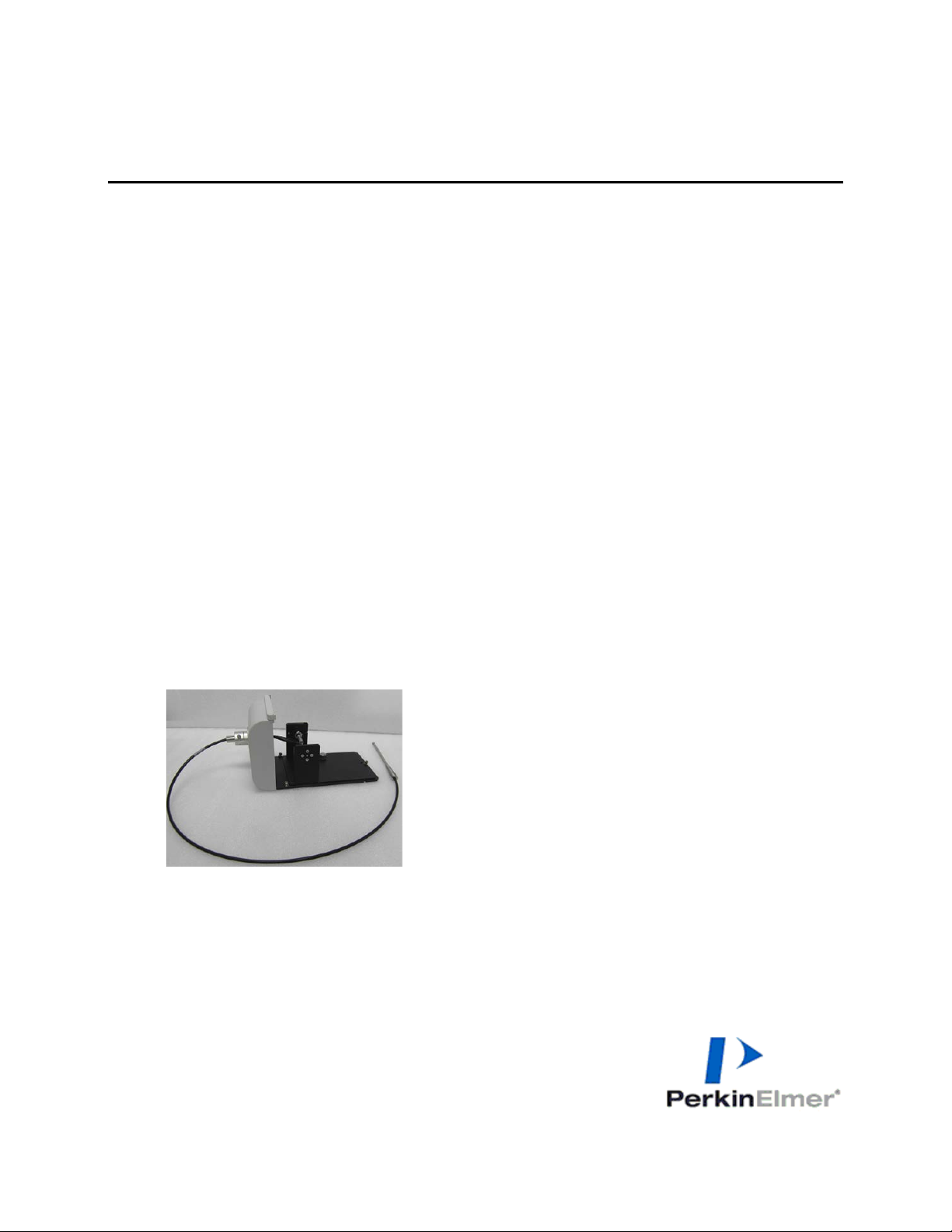
Figure 1 Lambda 365 Fiber Coupling Module [Part No: N4101013] with Fiber Optic
Probe [Part No: N4101048]
PerkinElmer, 710 Bridgeport Avenue,
Shelton, CT 06484-4794, U.S.A
Produced in the USA.
Page 2
2
Dimensions and Specifications
Breakout Length (BOL)
18 ~ 23cm
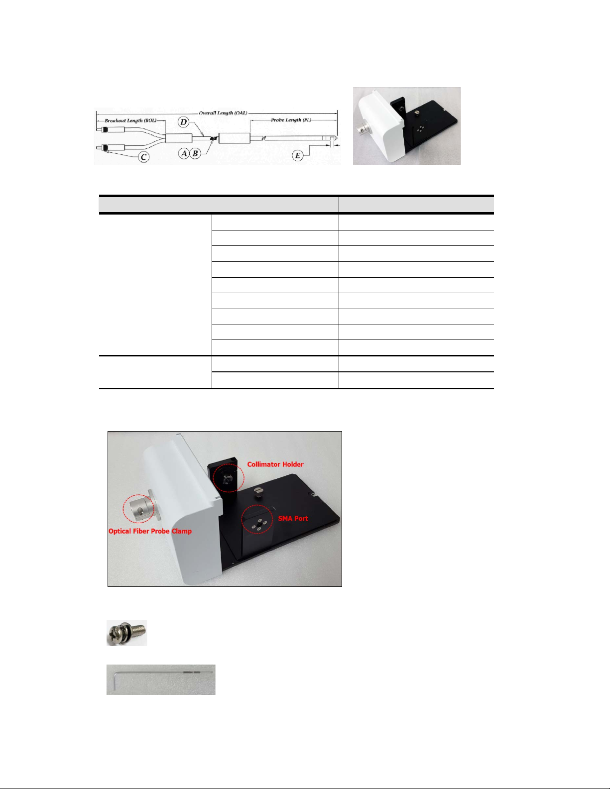
Configuration of Fiber Coupling Module
Figure 2 Fiber Optic Probe Figure 3 Fiber Coupling Module
Physical Characteristic Specification
A: Fiber Type Fused Silica
B: Fiber Size 600 µm
Fiber Optic Probe
(Part No: N4101048)
C: Connector SMA 905
D: Probe Diameter
E: Path Length 10 mm
Spectral Range 200 nm ~ 1100 nm
Overall Length (OAL) 100 ~ 120 cm
∅ 0.19” OD
09931262E
Fiber Coupling Module
(Part No: N4101013)
Probe Length (PL) 15.2 cm
Dimension (mm) 132(W) x 138(H) x 280(D)
Weight (Kg) 0.92
Figure 4 Fiber Coupling Module
- Used to fix a front plate for Fiber Coupling Module
- Spare screws (2ea) are enveloped with the accessory
Figure 5 Phillips round head screw with washer (M4 *12L)
Figure 6 1.5 mm wrench
Page 3
09931262E
3
Installation
1. Prepare the Lambda 365 Spectrophotometer to install this accessory.
2. Prepare the fiber coupling module and fiber optic probe.
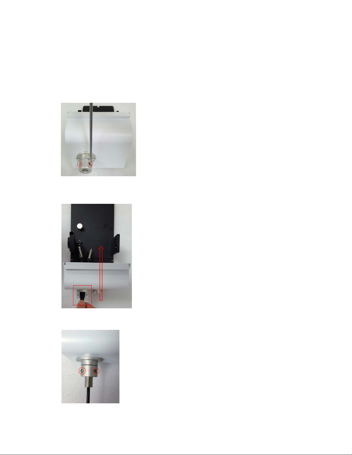
3. Remove the two M3x10L cross recessed flat head screws with washer using a Phillips screw driver.
Figure 7 Separate the optical fiber probe clamp
4. Insert connectors of the fiber optic probe trough the optical fiber probe clamp.
Figure 8 Inserting the fiber optic probe
5. Fix the two M3x10L cross recessed flat head screws.
Figure 9 Fixing two screws
Page 4
09931262E
4
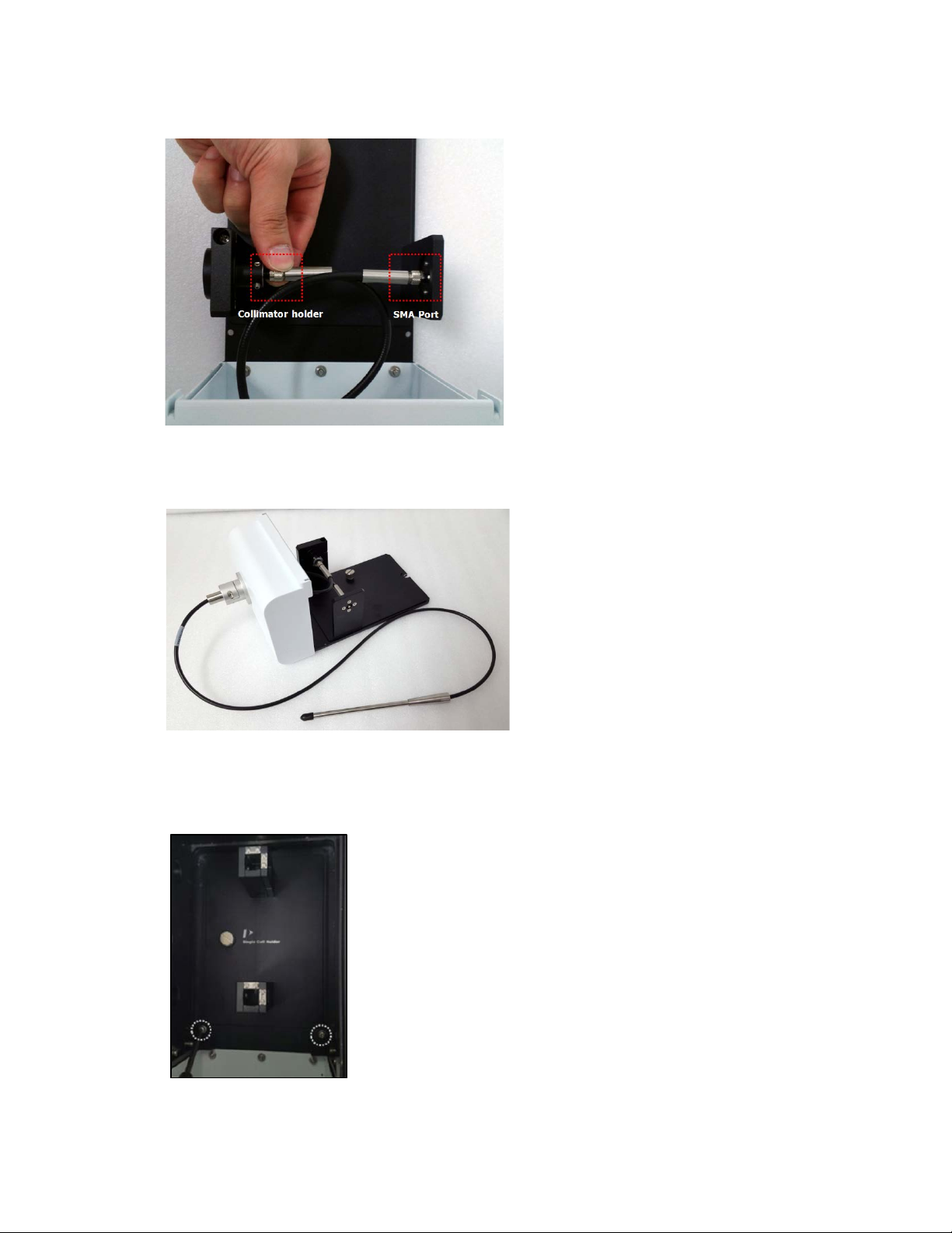
6. Connect the connectors of the fiber optic prober to the Collimator holder and the SMA port.
Figure 10 Connecting the fiber optic probe
7. Make sure that the fiber coupling module and fiber optic probe are connected correctly as below.
Figure 11 Fiber coupling module with fiber optic probe
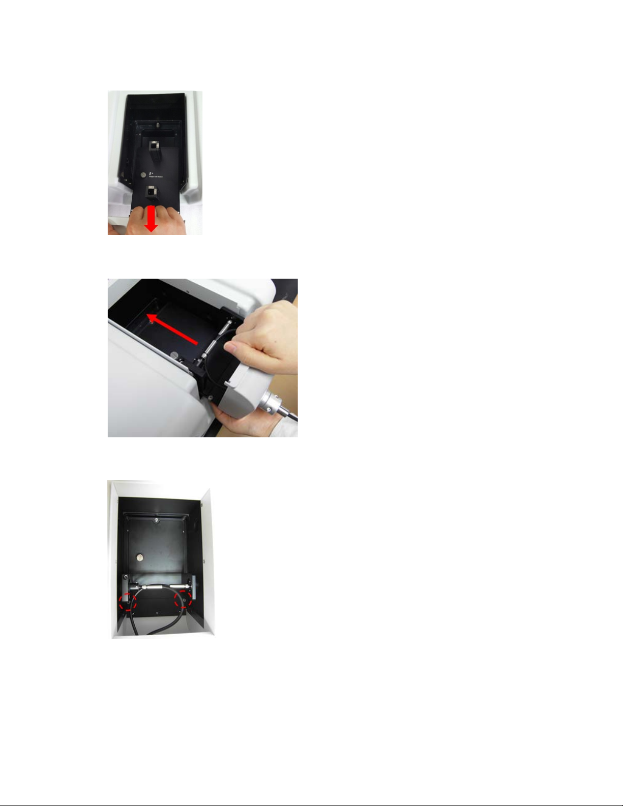
8. Remove the two Phillips round head screws with washer (M4*12L) to disassemble the existing cell
holder and base plate.
Figure 12 Location of the Phillips round head screws with washer (M4*12L)
Page 5
5
9. Pull out the cell holder and base plate by hand.
Figure 13 Pulling out the cell holder and base plate
10. Insert the Fiber Coupling Module with fiber optic probe into the sample compartment.
09931262E
Figure 14 Inserting the Fiber coupling module with fiber optic probe
11. Tighten the Fiber Coupling Module in the sample compartment with the screws.
Figure 15 Screw location
12. Dip the fiber optic probe into the liquid sample.
13. Align the optimum position by moving Fiber Optic Probe itself. The alignment procedure will be
described in the section of Alignment of Fiber Optic Probe.
Page 6
6
Measurement
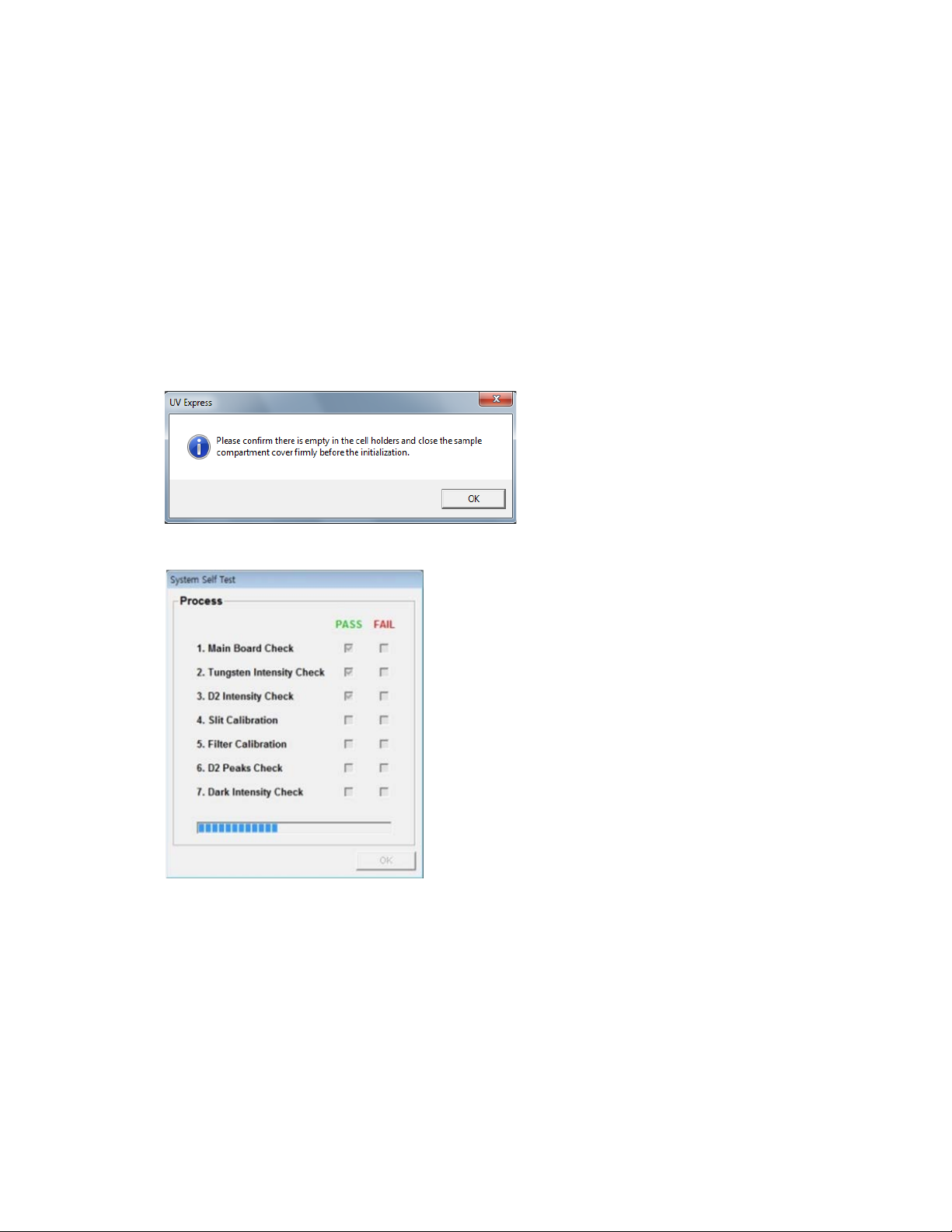
System Self Test
09931262E
NOTE:
NOTE:
The Fiber coupling module with fiber optic probe should be installed after System Self Test is finished.
Start the System Self Test after warming up the system for at least 20 minutes.
1. Install a single cell holder and base plate.
2. Double-click on the UV Express folder and select experiment mode for starting.
3. The following window will appear. Make sure that the sample compartment is closed firmly and
select OK.
4. Click OK after finishing the System Self Test.
Page 7
09931262E
7
Scan Mode
1. Install the fiber coupling module with fiber optic probe, referring to the “Installation” procedures
on page 3.
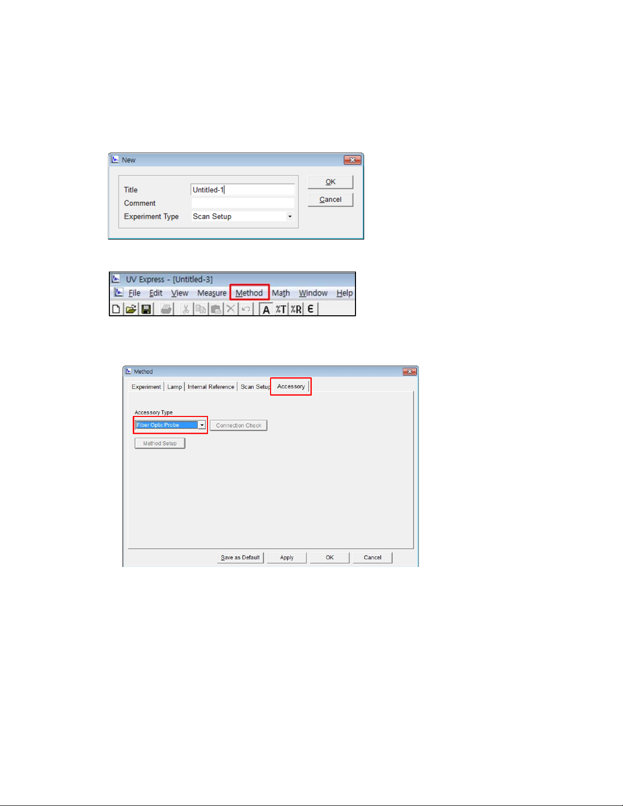
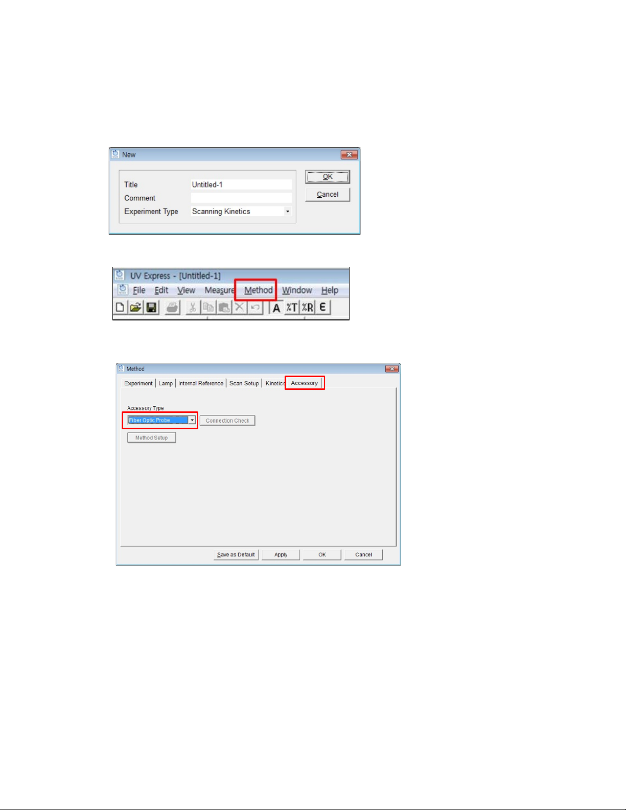
2. Select New to open a new window. Select Experiment Type and select OK.
3. Click Method and set up parameters.
4. Setup the experiment parameters as follows:
a. Accessory: Sel ect the Fiber Optic Probe.
Page 8

09931262E
8
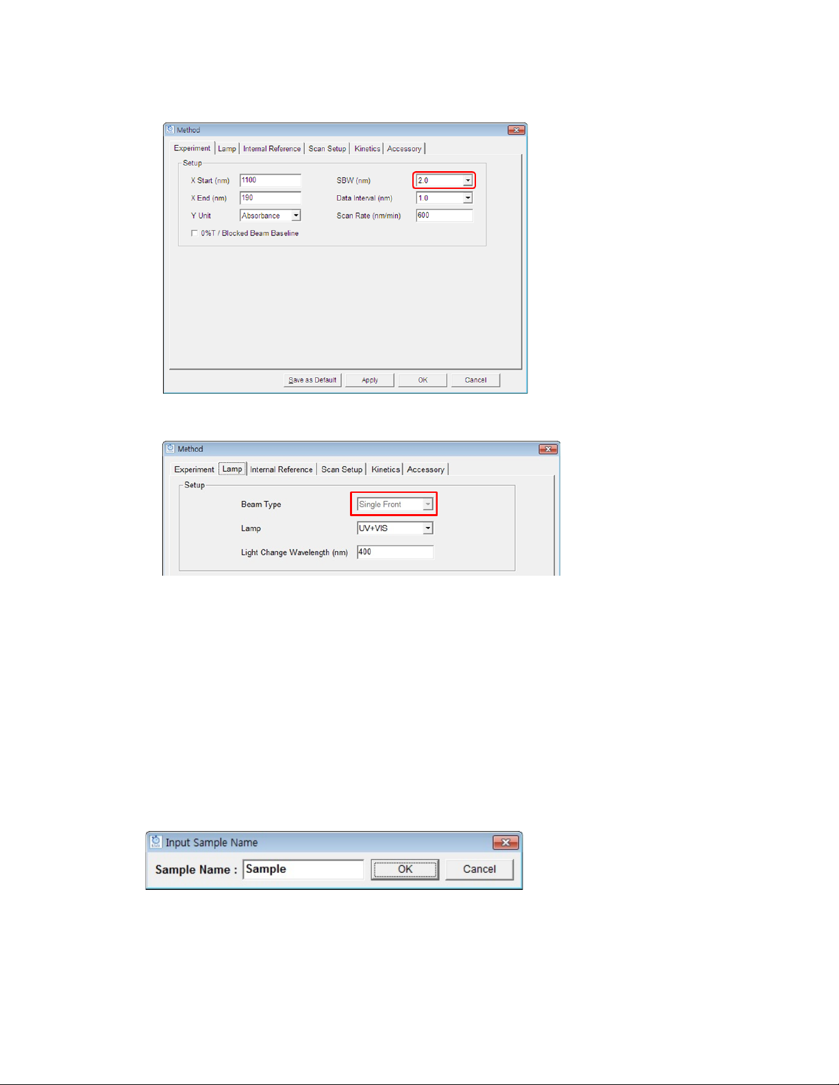
b. Experiment: SBW is set 2.0 nm automatically. Setup other experiment parameters.
c. Lamp: Single Front is automatically selected. If not, select Single Front and setup other
experiment parameters.
NOTE:
NOTE:
d. Setup the Internal Reference, Scan Setup. For more information, see the
Express Software Users Guide
5. Select Apply and OK after setting up the parameters.
6. Dip the probe in the blank solution and select the Blank icon.
, the section on
Scan Setup
.
Lambda 365 UV
Before measurement, make sure that that bubble does not exist at the mirror side of the probe.
When the sample is measured, any light from outside of the bottled should be blocked as it affects the
measurement result.
7. Clean the probe and dip it in the sample solution. Select the Sample icon.
8. Input the sample name and select OK.
9. The spectrum and result will be displayed. Save or print the results as desired.
Page 9

09931262E
9
Quantification Mode
1. Install the fiber coupling module with fiber optic probe, referring to the “Installation” procedures
on page 3.
2. Select New to open a new window. Select Experiment Type and select OK.
3. Select Method and set up the parameters.
4. Setup the experiment parameters as follows:
a. Accessory: Select the Fiber Optic Probe.
Page 10

09931262E
10
b. Experiment: SBW is set 2.0 nm automatically. Setup other experiment parameters.
c. Lamp: Single Front is automatically selected. If not, select Single Front and setup other
experiment parameters.
NOTE:
NOTE:
d. Setup the Quantification parameters. For more information, see the
Software Users Guide
5. Select Apply and OK after set-up of parameters.
6. Dip the probe in the blank solution and select the Blank icon. Absorbance of selected wavelength
is changed about 0 Abs.
, the section on
Quantification
.
Lambda 365 UV Express
Before measurement, make sure that that bubble does not exist at the mirror side of the probe.
When sample is measured, any light from outside of the bottled should be blocked as it affects the
measurement result.
7. Clean the probe and Dip the probe in the Standard solution. Select the Standard icon. Measure
standard solutions in order and the calibration curve will be created.
8. Clean the probe and dip the probe in the sample solution. Select the Sample icon.
9. Input sample name and select OK.
10. The spectrum and result will be displayed. Save or print results as desired.
Page 11
09931262E
11
Scanning Q uantification Mode
1. Install the fiber coupling module with fiber optic probe, referring to the “Installation” procedures
on page 3.
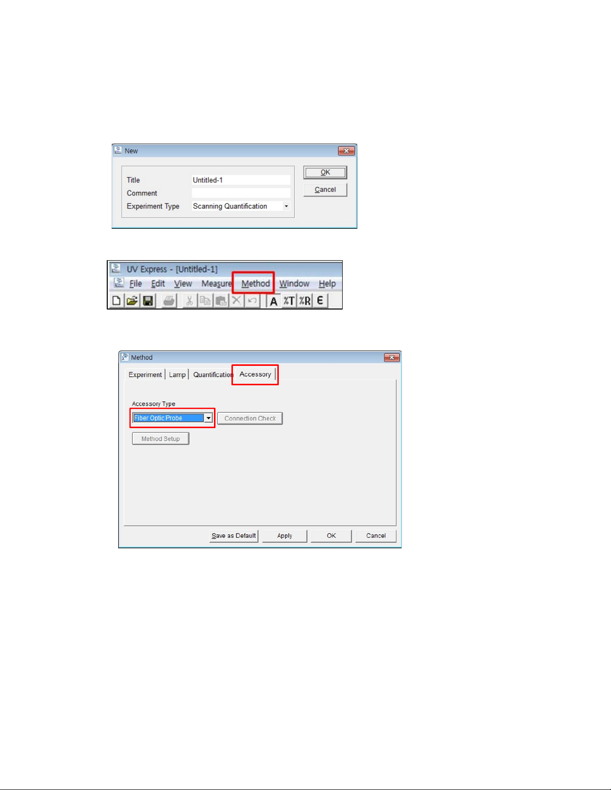
2. Select New to open a new window. Select Experiment Type and select OK.
3. Select Method and set up the parameters.
4. Setup the experiment parameters as follows:
a. Accessory: Select the Fiber Optic Probe.
Page 12

09931262E
12
b. Experiment: SBW is set 2.0 nm automatically. Setup other experiment parameters.
c. Lamp: Single Front is automatically selected. If not, select Single Front and setup other
experiment parameters.
NOTE:
NOTE:
d. Setup the Quantification parameters. For more information see the
Software Users Guide
5. Select Apply and OK after set-up of parameters.
6. Dip the probe in the blank solution and select the Blank icon. Absorbance of selected wavelength
is changed about 0 Abs.
, the section on
Scanning Quantification
.
Lambda 365 UV Express
Before measurement, make sure that that bubble does not exist at the mirror side of the probe.
When sample is measured, any light from outside of the bottled should be blocked as it affects the
measurement result.
7. Clean the probe and Dip the probe in the Standard solution. Select the Standard icon. Measure
standard solutions in order and the calibration curve will be created.
8. Clean the probe and dip the probe in the sample solution. Select the Sample icon.
9. Input sample name and select OK.
10. The spectrum and result will be displayed. Save or print results as desired.
Page 13

09931262E
13
Kinetics Mode
1. Install the fiber coupling module with fiber optic probe, referring to the “Installation” procedures
on page 3.
2. Select New to open a new window. Select Experiment Type and select OK.
3. Select Method and set up parameters.
4. Setup the experiment parameters as follows:
a. Accessory: Select the Fiber Optic Probe.
Page 14

09931262E
14
b. Experiment: SBW is set 2.0 nm automatically. Setup other experiment parameters.
c. Lamp: Single Front is automatically selected. If not, select Single Front and setup other
experiment parameters.
NOTE:
NOTE:
d. Setup the Kinetics parameters. For more information see the Lambda 365 UV Express Software
Users Guide, the section
5. Select Apply and OK after set-up of parameters.
6. Dip the probe in the blank solution and select the Blank icon. Absorbance of selected wavelength
is changed about 0 Abs.
Kinetics Mode
.
Before measurement, make sure that that bubble does not exist at the mir r or side of the probe.
When sample is measured, any light from outside of the bottled should be blocked as it affects the
measurement result.
7. Clean the probe and dip the probe in the sample solution. Select the Sample icon.
8. Input sample name and select OK.
9. The spectrum and result will be displayed. Save or print results as desired.
Page 15
09931262E
15
Scanning Kinetics Mode
1. Install the fiber coupling module with fiber optic probe, referring to the “Installation” procedures
on page 3.
2. Select New to open a new window. Select Experiment Type and select OK.
3. Select Method and set up parameters.
4. Setup the experiment parameters as follows:
a. Accessory: Select the Fiber Optic Probe.
Page 16
09931262E
16
b. Experiment: SBW is set 2.0 nm automatically. Setup other experiment parameters.
c. Lamp: Single Front is automatically selected. If not, select Single Front and setup other
experiment parameters.
NOTE:
NOTE:
d. Setup the Kinetics parameters. For more information see the
Users Guide
5. Select Apply and OK after set-up of parameters.
6. Dip the probe in the blank solution and select the Blank icon. Absorbance of selected wavelength
is changed about 0 Abs.
, the section
Scanning Kinetics Mode
.
Lambda 365 UV Express Software
Before measurement, make sure that that bubble does not exist at the mir r or side of the probe.
When sample is measured, any light from outside of the bottled should be blocked as it affects the
measurement result.
7. Clean the probe and dip it in the sample solution. Select the Sample icon.
8. Input sample name and select OK.
9. The spectrum and result will be displayed. Save or print results as desired.
Page 17
09931262E
17
Wavelength Program Mode
1. Install the fiber coupling module with fiber optic probe, referring to the “Installation” procedures
on page 3.
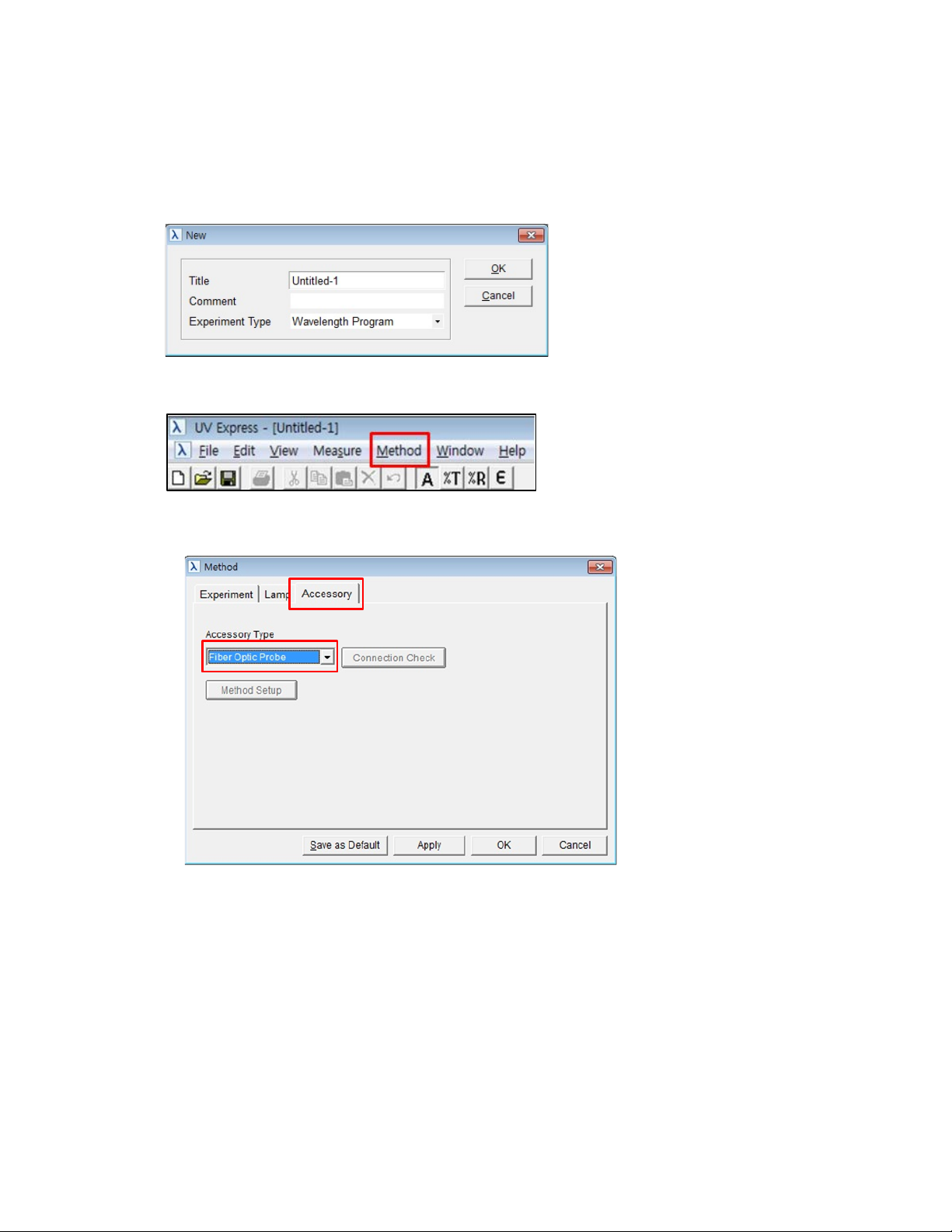
2. Select New to open a new window. Select Experiment Type and select OK.
3. Select Method and set up parameters.
4. Setup the experiment parameters as follows:
a. Accessory: Select the Fiber Optic Probe.
Page 18
09931262E
18
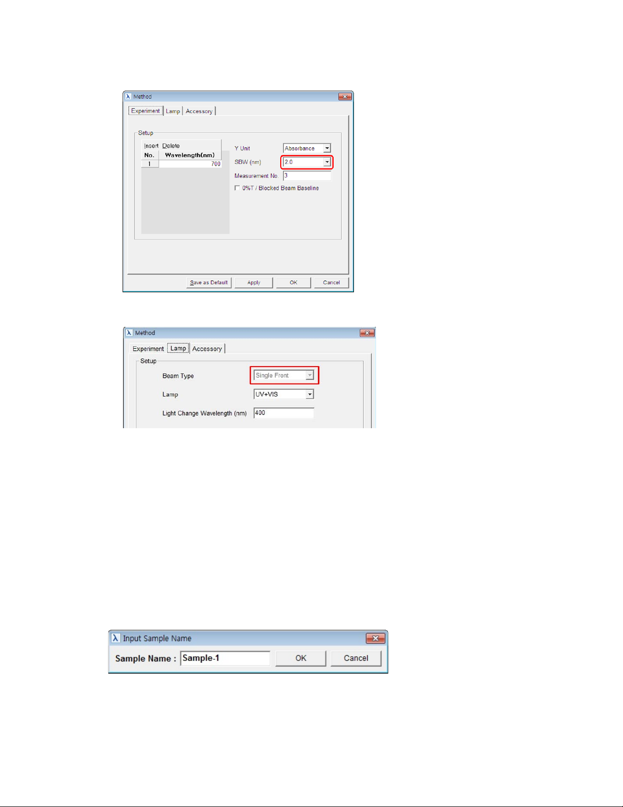
b. Experiment: SBW is set 2.0 nm automatically. Setup other experiment parameters.
c. Lamp: Single Front is automatically selected. If not, select Single Front and setup other
experiment parameters.
NOTE:
NOTE:
d. Setup the parameters. See the
Wavelength Program Mode
5. Select Apply and OK after setting up the parameters.
6. Dip the probe in the blank solution and select the Blank icon. Absorbance of selected wavelength
is changed about 0 Abs.
Lambda 365 UV Express Software Users Guide
.
, the section
Before measurement, make sure that that bubble does not exist at the mirror side of the probe.
When sample is measured, any light from outside of the bottled should be blocked as it affects the
measurement result.
7. Clean the probe and dip the probe in the sample solution. Select the Sample icon.
8. Input sample name and select OK.
9. The spectrum and result will be displayed. Save or print results as desired.
Page 19

19
Alignment of F ibe r O p tic Probe
09931262E
NOTE:
When the fiber optic probe is assembled to the fiber coupling module for the first time, or if the alignment
is inaccurate, i.e., the intensity is too low or saturated; you need to perform the intensity alignment as
described in the following procedures.
1. Execute the Scan mode of UV Express softwar e.
2. Setup the experiment parameters as follows:
a. Accessory: Select the Fiber Optic Probe.
b. Experiment: SBW is set 2.0 nm automatically. Setup other experiment parameters as follows.
c. Lamp: Single Front is automatically selected. If not, select Single Front and setup other
experiment parameters.
3. Select Apply and OK after setting up the parameters.
4. Dip the probe in the blank solution and select the Blank icon.
Page 20

09931262E
20
5. If the baseline measurement has abnormal results, the Fiber Optic Probe has to be aligned.
Ex) Intensity is too low.
6. Loosen the three M3 setscrews on the collimator holder using a 1.5 mm wrench.
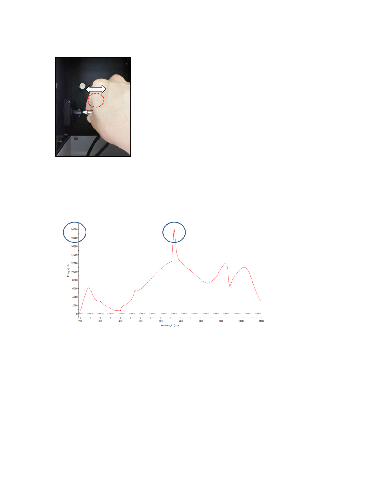
7. Move slightly back and forth the fiber optic probe connector to the light source side for the
alignment, and then tighten the screw on the collimator holder.
Page 21
09931262E
21
8. After finishing the alignment, measure baseline again to check suitability. If it is fine, measure the
sample. (Maximum intensity should be over 2000 cnt.) If not, repeat the alignment procedure 1
to 7 above.
Page 22

09931262E
22
 Loading...