

Page 1

MOLECULAR SPECTROSCOPY
FRONTIER IR SINGLE-RANGE SYSTEMS
User’s Guide
Page 2

Release History
Part Number Release Publication Date
L1050101 B July 2013
Any comments about the documentation for this product should be addressed to:
User Assistance
PerkinElmer Ltd
Chalfont Road
Seer Green
Beaconsfield
Bucks HP9 2FX
United Kingdom
Or emailed to: info@perkinelmer.com
Notices
The information contained in this document is subject to change without notice.
Except as specifically set forth in its terms and conditions of sale, PerkinElmer makes no
warranty of any kind with regard to this document, including, but not limited to, the
implied warranties of merchantability and fitness for a particular purpose.
PerkinElmer shall not be liable for errors contained herein for incidental consequential damages in
connection with furnishing, performance or use of this material.
Copyright Information
This document contains proprietary information that is protected by copyright.
All rights are reserved. No part of this publication may be reproduced in any form whatsoever or
translated into any language without the prior, written permission of PerkinElmer, Inc.
Copyright © 2013 PerkinElmer, Inc.
Produced in the UK.
Trademarks
Registered names, trademarks, etc. used in this document, even when not specifically marked as such,
are protected by law.
PerkinElmer is a registered trademark of PerkinElmer, Inc.
Spectrum, AssureID and Frontier are trademarks of PerkinElmer, Inc.
Page 3

Table of Contents
Introduction ............................................................................................... 5
About This Manual ............................................................................................ 6
Conventions Used in this Manual ........................................................................ 7
Notes, Cautions and Warnings ..................................................................... 7
Warnings and Safety Information ........................................................... 11
Safety Summary ...............................................................................................12
General Safety .................................................................................................13
Location and Ventilation ...................................................................................14
To allow for adequate cooling ....................................................................14
To allow any nitrogen used to disperse .......................................................14
Use of flammable solvents and samples ......................................................15
Electrical Safety ...............................................................................................16
Laser Safety Regulations...................................................................................17
Radiation Hazards and their Classification ..........................................................18
Laser radiation ..........................................................................................18
Radiation emitted by the Frontier FT-NIR ....................................................18
Labels .............................................................................................................19
Warning Signs on the Instrument ......................................................................21
EMC Compliance ..............................................................................................22
European EC Directive ...............................................................................22
FCC rules and regulations...........................................................................22
An Overview of the Frontier IR Single-Range Spectrometers ................. 23
A Guided Tour of the Frontier IR Single-Range Spectrometers ............................24
Optical system ...........................................................................................25
Top panel controls .....................................................................................26
The sample compartment ..........................................................................26
Internal accessories ...................................................................................27
External accessories ...................................................................................28
Imaging systems .......................................................................................29
Storage compartment ................................................................................29
Power switch and communication ports ......................................................29
Accessories ......................................................................................................30
Frontier IR Sytems Upgrades ............................................................................31
Unpacking and Installation ...................................................................... 33
Requirements ..................................................................................................34
Electrical requirements ...............................................................................34
Environment ..............................................................................................34
Unpacking the Spectrometer .............................................................................35
Opening the shipping container ..................................................................35
The Desiccant Indicator ....................................................................................37
Connecting up the Spectrometer .......................................................................38
Connecting to the PC .................................................................................38
Other connectors .......................................................................................39
Connecting the spectrometer to the electrical supply ...................................40
Installing the Instrument in the Software ...........................................................42
Installing the software ...............................................................................42
The Instrument Install Wizard ....................................................................42
Using the Spectrometer with Spectrum .................................................. 43
Basics of Software Control ................................................................................44
Starting Spectrum software ........................................................................44
Scanning samples ......................................................................................45
Working with the instrument display and Go button .....................................46
Changing the beam path ............................................................................46
Using the Spectrum on-screen Help system .................................................47
Page 4

Atmospheric (CO2/H2O) Suppression ................................................................. 48
What is atmospheric suppression? .............................................................. 48
What does atmospheric suppression do? .................................................... 48
AVI Correction ................................................................................................. 50
What is AVI correction? ............................................................................. 50
What does AVI correction do? .................................................................... 50
Look Ahead ..................................................................................................... 51
What is Look Ahead? ................................................................................. 51
What does Look Ahead do? ....................................................................... 51
Quality Checks ................................................................................................. 52
What are Quality Checks? .......................................................................... 52
What do Quality Checks do? ...................................................................... 52
Routine Maintenance ............................................................................... 53
Cleaning the Spectrometer ............................................................................... 54
Cleaning the display .................................................................................. 54
Moving the Spectrometer ................................................................................. 55
Condensation ............................................................................................ 55
The Desiccant Indicator in Detail ...................................................................... 56
Changing the Desiccant.................................................................................... 57
Renewing the instrument desiccant ............................................................ 58
Installing rechargeable desiccant in the instrument ..................................... 59
Purging the Spectrometer ................................................................................ 60
Changing the External Fuse .............................................................................. 63
Cooling the MCT Detector (If Fitted) ................................................................. 65
Advanced Maintenance ............................................................................ 69
Opening the Main Cover ................................................................................... 70
Replacing the Source ....................................................................................... 74
Replacing the Beamsplitter ............................................................................... 76
Installing/Replacing Windows ........................................................................... 78
Installing Filters in the Filter Wheel ................................................................... 80
Replacing the Laser and Power Supply .............................................................. 84
Replacing the laser and power supply (External Beam Pack option fitted) ..... 86
Appendices ............................................................................................... 89
Appendix 1: Changing the Sampling Accessory .................................................. 90
Appendix 2: Instrument Self-Checks ................................................................. 92
Appendix 3: Instrument Performance Validation Kits .......................................... 94
Appendix 4: Decontamination and Cleaning ....................................................... 95
Appendix 5: WEEE Instructions for PerkinElmer Products ................................... 96
Index .............................................................................................................. 97
Page 5

Introduction
Page 6

6 . Frontier IR Single-range Spectrometers User's Guide
About This Manual
This manual contains the following sections:
• Introduction
• Warnings and Safety Information
• An Overview of the Frontier IR Single-Range Spectrometers
• Unpacking and Installation
• Using the Spectrometer with Spectrum
• Routine Maintenance
• Advanced Maintenance
• Appendices.
For further information on collecting, viewing and processing spectra using Spectrum
software, refer to the help file that you can access from the Help menu, or by clicking Help
on a dialog.
NOTE: This manual shows details for using your instrument with the Spectrum software
package (version 10 or later). If you have Spectrum ES or AssureID software, please
refer to the Administrator’s Guide for your software which can be found on the
IR & Raman Manuals CD
(L1050002), or refer to the on-screen Help.
Page 7

Introduction . 7
Conventions Used in this Manual
Normal text is used to provide information and instructions.
Bold text refers to text that is displayed on the screen.
UPPERCASE text, for example ENTER or ALT, refers to keys on the PC keyboard. '+' is
used to show that you have to press two keys at the same time, for example, ALT+F.
All eight digit numbers are PerkinElmer part numbers unless stated otherwise.
The term ‘instrument’ refers to the mid- or near-infrared Frontier IR spectrometers, and any
sampling accessory fitted.
Notes, Cautions and Warnings
Three terms, in the following standard formats, are also used to highlight special
circumstances and warnings.
NOTE: A note indicates additional, significant information that is provided with some
procedures.
Page 8

8 . Frontier IR Single-range Spectrometers User's Guide
警告
警告
We use the term WARNING to inform you about situations that could result in
personal injury to yourself or other persons. Details about these
circumstances are in a box like this one.
WARNING
Warning (Warnung)
Bedeutet, daß es bei Nichtbeachten der genannten Anweisung zu einer
Verletzung des Benutzers kommen kann.
Warning (Advarsel)
Betyder, at brugeren kan blive kvæstet, hvis anvisningen ikke overholdes.
Warning (Peligro)
Utilizamos el término WARNING (PELIGRO) para informarle sobre
situaciones que pueden provocar daños personales a usted o a otras
personas. En los recuadros como éste se proporciona información sobre este
tipo de circunstancias.
Warning (Danger)
Nous utilisons la formule WARNING (DANGER) pour avertir des situations
pouvant occasionner des dommages corporels à l'utilisateur ou à d'autres
personnes. Les détails sur ces circonstances sont données dans un encadré
semblable à celui-ci.
Warning (Pericolo)
Con il termine WARNING (PERICOLO) vengono segnalate situazioni che
potrebbero provocare incidenti alle persone. Troverete informazioni su tali
circostanze in un riquadro come questo.
Warning (Waarschuwing)
Betekent dat, wanneer de genoemde aanwijzing niet in acht wordt genomen,
dit kan leiden tot verwondingen van de gebruiker.
Warning (Aviso)
Significa que a não observância da instrução referida poderá causar um
ferimento ao usuário.
Warning (
我们使用“警告”这一术语来通知您有关可能会对您自己或他人造成人
)
身伤害的情况。
有关这些情况的详细信息可在此类方框中找到。
Warning (
使用者及びその他周辺に危害が及ぶ恐れがある場合は、
この様なボックスの中に注意事項が表示されています。
)
Page 9

CAUTION
小心
本仪器或其它设备造成严重损害
注意
Introduction . 9
We use the term CAUTION to inform you about situations that could result in
serious damage to the instrument or other equipment. Details about these
circumstances are in a box like this one.
Caution (Achtung)
Bedeutet, daß die genannte Anleitung genau befolgt werden muß, um einen
Geräteschaden zu vermeiden.
Caution (Bemærk)
Dette betyder, at den nævnte vejledning skal overholdes nøje for at undgå en
beskadigelse af apparatet.
Caution (Advertencia)
Utilizamos el término CAUTION (ADVERTENCIA) para advertir sobre
situaciones que pueden provocar averías graves en este equipo o en otros. En
recuadros éste se proporciona información sobre este tipo de circunstancias.
Caution (Attention)
Nous utilisons le terme CAUTION (ATTENTION) pour signaler les situations
susceptibles de provoquer de graves détériorations de l'instrument ou
d'autre matériel. Les détails sur ces circonstances figurent dans un encadré
semblable à celui-ci.
Caution (Attenzione)
Con il termine CAUTION (ATTENZIONE) vengono segnalate situazioni che
potrebbero arrecare gravi danni allo strumento o ad altra apparecchiatura.
Troverete informazioni su tali circostanze in un riquadro come questo.
Caution (Opgelet)
Betekent dat de genoemde handleiding nauwkeurig moet worden opgevolgd,
om beschadiging van het instrument te voorkomen.
Caution (Atenção)
Significa que a instrução referida tem de ser respeitada para evitar a
danificação do aparelho.
Caution (
我们使用“小心”这一术语来通知您有关可能会对
)
的情况。
有关这些情况的详细信息可在此类方框中找到。
Caution (
分光器や他の機材等に深刻なダメージを与える恐れがある場合は、
この様なボックスの中に表示しています。
)
Page 10

10 . Frontier IR Single-range Spectrometers User's Guide
Page 11

Warnings and Safety
Information
Page 12

12 . Frontier IR Single-range Spectrometers User's Guide
Safety Summary
The Frontier IR spectrometers have been designed to comply with a wide variety of
international standards governing the safety of laboratory equipment. In routine use, the
instruments pose virtually no risk to you. If you take some simple, common-sense
precautions, you can make sure that you maintain the continued safe operation of your
instrument:
DO make sure that the instrument is properly connected to the electrical supply; in particular
make sure that the ground (earth) is securely connected.
DO disconnect the electrical power cable before opening the main cover of the instrument.
DO keep the instrument dry. Avoid spilling liquid into the instrument. Clean all external spills
immediately. If anything that is spilled enters the main body of the instrument, switch off the
power and contact a PerkinElmer Service Engineer.
DO NOT stare into the internal laser beam under the instrument cover. The instrument
contains a low power, visible (red) laser; momentary exposure to the beam is not dangerous,
but deliberate, direct viewing of the beam along its axis could damage your eye.
DO NOT use a flammable gas to purge the instrument. The instrument contains a hot source,
and a fire or explosion will result. Only use clean, dry, oil-free nitrogen or air to purge the
instrument.
DO read the more detailed information on warnings and safety in the following pages to
ensure the safe operation of the instrument.
Page 13

Warnings and Safety Information . 13
General Safety
The Frontier IR spectrometers have been designed and tested in accordance with
PerkinElmer specifications and in accordance with the safety requirements of the
International Electrotechnical Commission (IEC). The instruments conform to IEC publication
61010-1 (“Safety requirements for electrical equipment for measurement, control, and
laboratory use”) as it applies to IEC Class 1 (earthed) appliances and therefore meets the
requirements of EC low voltage directive 2006/95/EC.
If the instrument is used in a manner not specified by the manufacturer, the protection
provided by the instrument may be impaired. Only use the instrument indoors and under the
following conditions:
Temperature 15 °C to 35 °C
Relative Humidity 80% maximum (non-condensing)
If possible, avoid any adjustment, maintenance and repair of the opened, operating
instrument. If any adjustment, maintenance and repair of the opened, operating instrument
is necessary, this must only be done by a skilled person who is aware of the hazard involved.
Whenever it is likely that the instrument is unsafe, make it inoperative. The instrument may
be unsafe if it:
• Shows visible damage
• Fails to perform the intended measurement
• Has been subjected to prolonged storage in unfavorable conditions
• Has been subjected to severe transport stresses.
If the equipment is used in a manner not specified herein the protection
provided by the equipment may be impaired.
WARNING
The instrument has been designed to be safe under the following environmental conditions:
• Indoor use
• Altitude up to 2000 m (above mean sea level)
• Ambient temperatures of 5 °C to 40 °C
• A maximum ambient relative humidity of 80% for temperatures up to 31 °C, decreasing
linearly to 50% relative humidity at 40 °C
• Mains supply fluctuations not exceeding ±10% of the nominal voltage.
Page 14

14 . Frontier IR Single-range Spectrometers User's Guide
Location and Ventilation
Make sure that the switch at the electrical supply inlet on the rear of the
instrument is not obstructed.
WARNING
To allow for adequate cooling
Do not site the instrument near to room heating equipment, for example, central heating
radiators.
During operation, there should be a minimum gap of:
• 15 cm (6 inches) between any surface and the cooling louvers at the rear of the
instrument.
• 7 cm (3 inches) between the instrument and adjacent equipment.
• 45 cm (18 inches) between any surface and the top surface of the closed sample area lid
(to allow for the lid to be opened fully).
To allow any nitrogen used to disperse
Do not site the instrument in a poorly ventilated area if nitrogen will be
used as a purge gas, or if liquid nitrogen will be used to cool a detector.
WARNING
The spectrometer includes a coupling that enables the instrument body, and another
coupling that enables the sample compartment, to be purged using clean, dry, oil-free air or
nitrogen. The recommended flow rate to each connector is 10 l/min, and both the instrument
and the sample compartment vent to their surroundings.
If the instrument is fitted with an MCT detector, this is cooled using liquid nitrogen. A risk
assessment should include personal protection protocols, and proper actions in the event of
accidental spillage. 1 l (2 US pints) of liquid nitrogen evolves to 700 l (approximately
25 cubic feet) of nitrogen gas, and the cold vapor can pool at floor level.
Oxygen depletion in an enclosed space does not trigger a gasping reflex,
and errors of judgment, confusion, or unconsciousness can occur in
seconds and without warning.
Page 15

Warnings and Safety Information . 15
Use of flammable solvents and samples
The instrument contains a hot source and contact with flammable vapors
may cause an explosion. When working with flammable solvents or
samples, particularly during unattended operation with flow-cells, it is
WARNING
WARNING
recommended that the instrument optics area should be continuously
purged with dry air or nitrogen to maintain a positive pressure and
prevent flammable vapor from entering the instrument.
If flammable solvents or samples are spilled on the instrument and there
is any possibility that they have entered the interior (by coming into
contact with cover gaskets, for example) then the instrument must be
switched off immediately and disconnected from the power supply. The
optics area should then be thoroughly purged with dry air or nitrogen, or
the main cover should be opened to thoroughly ventilate the optics area
before proceeding.
WARNING
WARNING
Flammable solvents or samples should not be stored on or near the
instrument. Handling of such materials during preparation should be
performed in a safe area away from the instrument such as a fume
cabinet.
Do not use a flammable gas to purge the Frontier IR instruments. Use
only clean, dry, oil-free nitrogen or air.
Page 16

16 . Frontier IR Single-range Spectrometers User's Guide
Electrical Safety
• Connect the instrument to a power supply line that includes a switch or other means of
disconnection from the electricity supply.
• Only plug the instrument into an electricity-supply socket that is provided with a
protective earth connection.
• When fuses need replacing, use only those with the required current rating and of the
specified type. Do not use makeshift fuses and do not short-circuit fuse holders.
• When the instrument is connected to its electricity supply, terminals may be live and the
removal of covers other than those which can be removed by hand is likely to expose
live parts.
• Capacitors inside the instrument may still be charged even if the instrument has been
disconnected from all voltage sources.
• The instrument must be disconnected from all voltage sources before it is opened for
any adjustment, replacement, maintenance or repair.
Any interruption of the protective earth conductor inside or outside the
instrument or disconnection of the protective earth terminal can make the
instrument dangerous.
WARNING
The instrument has an IEC Insulation Class I rating for external circuits – only connect other
equipment that meets the requirements of IEC 61010-1, IEC 60950 or equivalent standards.
Page 17

Warnings and Safety Information . 17
Laser Safety Regulations
The Frontier IR spectrometers are Class 1 laser products as defined by IEC 60825-1. The
optical module contains a Class 2 Helium Neon (HeNe) laser, which emits visible, continuous
wave radiation at a wavelength of 633 nm and has a maximum output power of 1 mW. Some
diffuse HeNe laser radiation, within Class 1 limits, emerges from:
• The window in the left hand side of the sample compartment when an internal beam
path is selected.
• An external beam port when the beam port cover is removed, no accessory is fitted at
the port, and the beam path to the port is selected.
Do not stare into any laser beam. Staring into a laser beam (intrabeam
viewing) can cause permanent damage to your eyes.
WARNING
The laser is automatically shut down when the main cover of the instrument is raised.
Do not attempt to override or modify the interlock system.
Use of controls or adjustments or performance of procedures other than
WARNING
The instrument complies with the following laser safety regulations:
1. 21 CFR Part 1040.10 and 1040.11 except for deviations pursuant to Laser Notice No.50
dated 24 June 2007. Administered by the Center for Devices and Radiological Health,
U.S. Department of Health and Human Services.
2. European Standard EN 60825-1:2007 – “Safety of laser products – Part 1: Equipment
classification and requirements”.
those specified herein may result in hazardous radiation exposure.
Page 18

18 . Frontier IR Single-range Spectrometers User's Guide
Radiation Hazards and their Classification
Laser radiation
Indirect observation of the laser beam radiation in the optical path is not hazardous. Directly
viewing the laser beam along its axis (allowing the laser beam radiation to pass into the eye)
can be hazardous, depending upon the power of the beam, the length of time that the eye is
exposed to the beam and the optical efficiency of the exposed eye. Direct viewing of a laser
beam along its axis is termed
Protection of the eye during accidental, momentary intrabeam viewing of a Class 2 laser
beam is normally given by the eye’s aversion response, including the blink reflex, which limits
exposure of the eye to less than 0.25 seconds.
Class 1 levels of laser radiation are not considered to be hazardous.
intrabeam
Radiation emitted by the Frontier FT-NIR
The Frontier IR FT-NIR quartz halogen bulb, which produces the near infra-red beam, emits
ultraviolet, visible and infrared radiation. The majority of this radiation is in the infrared
region. Do not stare into the beam produced by this bulb.
viewing.
Measurements of the infrared radiation emitted from the sample area show that exposure
limits recommended by the American Conference of Governmental Industrial Hygienists
(ACGIH) and International Commission on Non-Ionizing Radiation Protection (ICNIRP) will
not be exceeded during normal operation.
Page 19
Warnings and Safety Information . 19
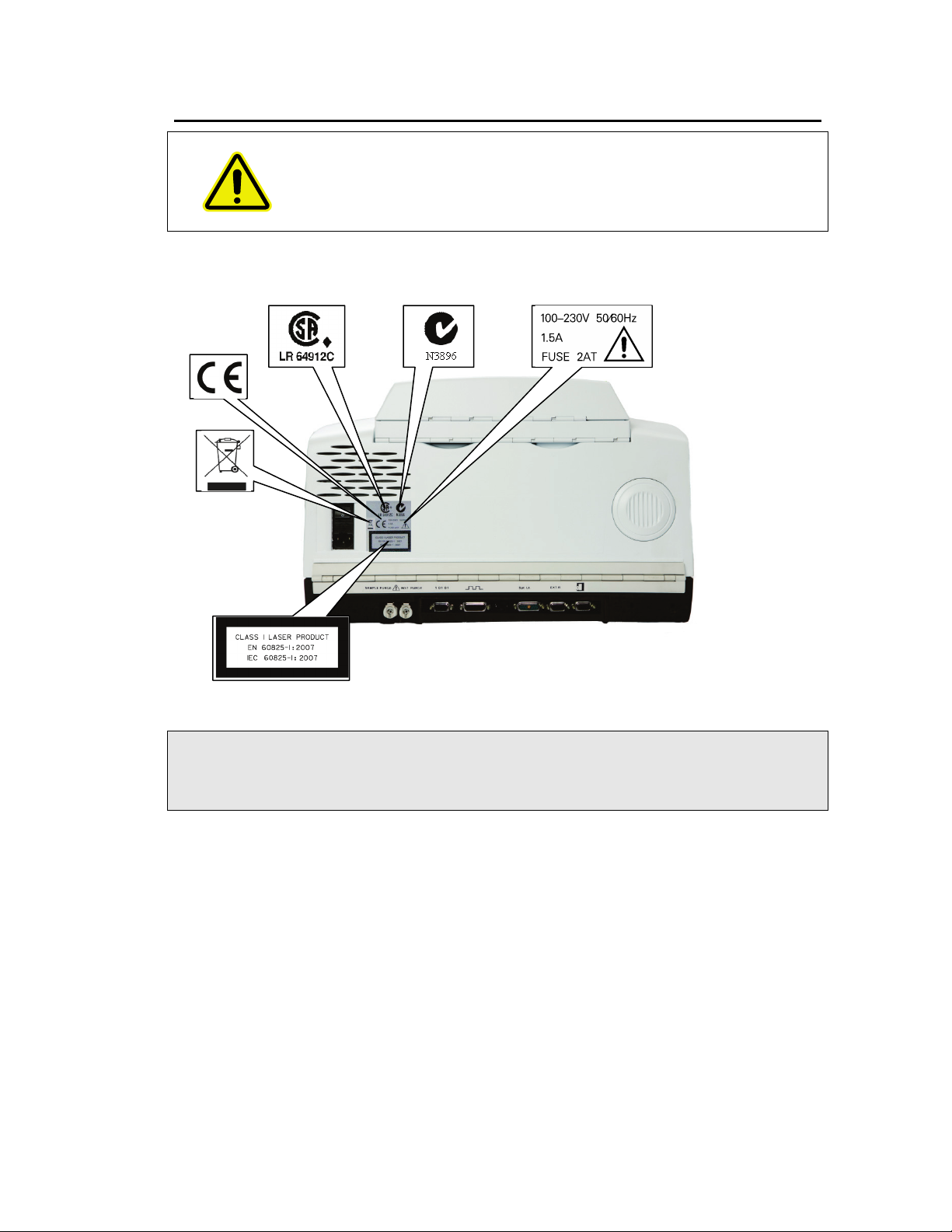
Labels
When this label is attached to an instrument it means ‘Caution, risk of
danger’. Refer to the manual to find out the nature of the potential
hazard and any actions that have to be taken.
The product identification label is on the front of the instrument. Other labels are fixed to the
Frontier IR spectrometers in the locations shown in Figure 1 and Figure 2:
Figure 1 Labels (rear of instrument)
NOTE: The label with a crossed-out wheeled bin symbol and a rectangular bar indicates that
the product is covered by the Waste Electrical and Electronic Equipment (WEEE)
Directive.
page 96.
Refer to Appendix 5: WEEE Instructions for PerkinElmer Products
on
Page 20

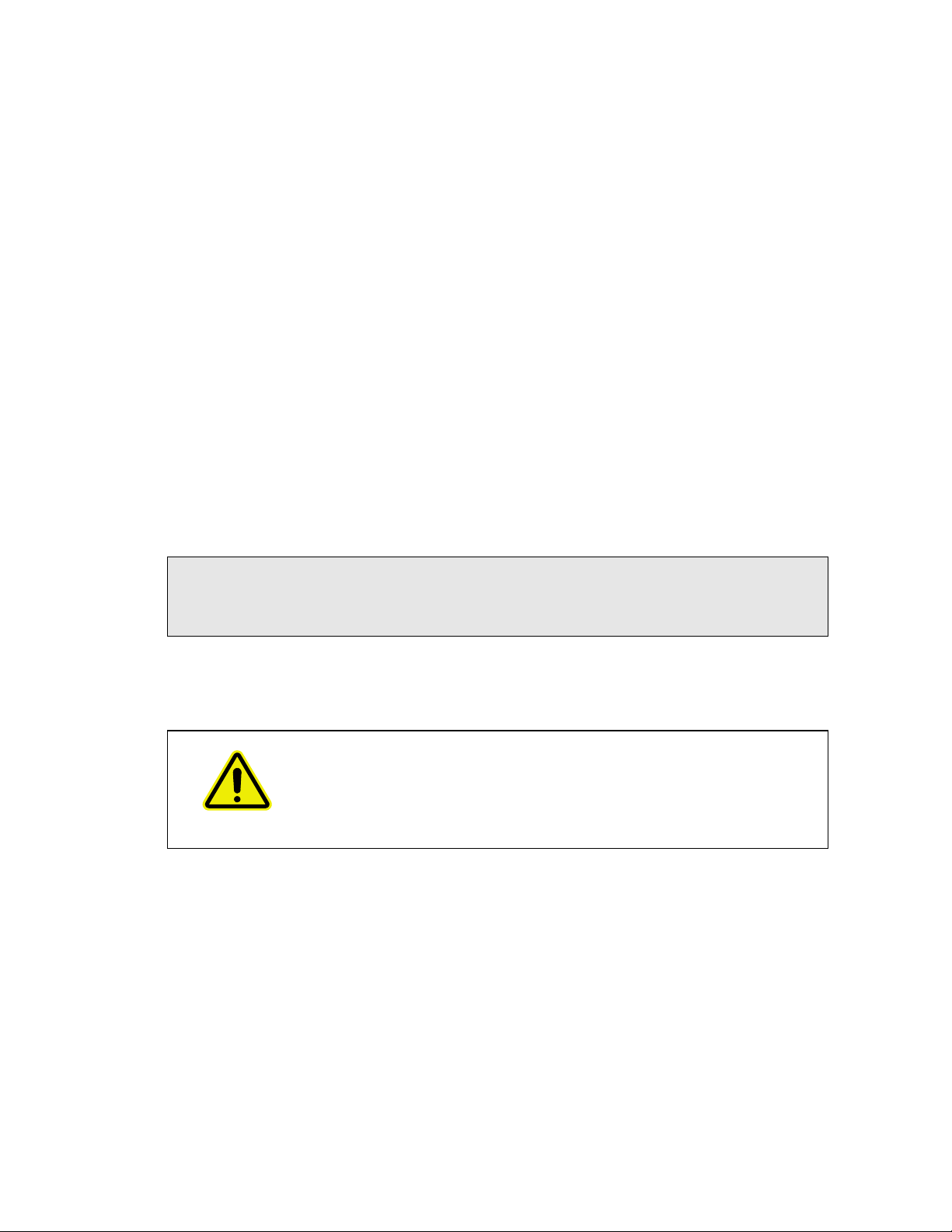
20 . Frontier IR Single-range Spectrometers User's Guide
Serial number, part
number and date of
manufacture
NOTE: There is a second copy of the CAUTION label inside the sample compartment cover.
Figure 2 Labels (sample compartment)
Page 21

Warnings and Safety Information . 21
have
Warning Signs on the Instrument
Caution, hot surface.
Caution, risk of electric shock.
Caution, laser radiation hazard.
Caution, risk of danger.
Refer to accompanying documents in all cases where this symbol is used
to find out the nature of the potential hazard and any actions which
to be taken.
Page 22

22 . Frontier IR Single-range Spectrometers User's Guide
EMC Compliance
European EC Directive
The Frontier IR spectrometers have been designed and tested to meet the requirements of
the EC Directive 2004/108/EC.
FCC rules and regulations
These products are classified as digital devices used exclusively as industrial, commercial, or
medical test equipment. They are exempt from the technical standards specified in Part 15 of
the FCC Rules and Regulations, based on Section 15.103(c).
Page 23

An Overview of the
Frontier IR Single-Range
Spectrometers
Page 24

24 . Frontier IR Single-range Spectrometers User's Guide
A Guided Tour of the Frontier IR Single-Range Spectrometers
PerkinElmer Frontier IR single-range spectrometers are bench-top FT-IR instruments.
Figure 3 Frontier IR Systems spectrometer
• Frontier FT-IR spectrometers:
– The optical system enables you to collect data over a total range of
8300 to 350 cm
– A LiTaO
MIR detector.
3
−1
with a best resolution of 0.4 cm−1.
– Optional gold optics.
– Optional MCT detector.
• Frontier Performance Pack Systems FT-IR spectrometers:
– The optical system enables you to collect data over a total range of
8300 to 350 cm
−1
with a best resolution of 0.4 cm−1.
– A DTGS (deuterated triglycine sulfate) MIR detector as standard for enhanced
signal-to-noise.
– Optional gold optics.
– Optional MCT detector.
• Frontier Extended Range Performance Pack FT-IR spectrometers:
– The optical system with CsI beamsplitter enables you to collect data over a total
range of 7800 to 225 cm
−1
with a best resolution of 0.4 cm−1.
– A DTGS (deuterated triglycine sulfate) MIR detector as standard.
– Optional gold optics.
– Optional MCT detector.
• Frontier FT-NIR spectrometers:
– The optical system enables you to collect data over a total range of
14700 to 2000 cm
−1
with a best resolution of 0.5 cm−1.
– An NIR DTGS (deuterated triglycine sulfate) detector.
– Gold optics as standard.
The instrument can operate in ratio, single-beam, or interferogram mode.
Page 25
An Overview of the Frontier IR Single-Range Spectrometers . 25
The instrument is connected to a PC, either point-to-point or over a network. The Spectrum
software package supplied enables you to control the instrument and to manipulate the
spectra that you collect.
Optical system
The optical system is under the main cover of the system. Usually the main cover of the
instrument is closed, but to perform most maintenance tasks the cover has to be open. When
you do this, a safety interlock automatically switches off the power. Nevertheless, the
instrument should be disconnected from the mains before opening the main cover for
maintenance.
Consistent, reliable performance is achieved by having few moving or adjustable parts, and
by extensive insulation of the optical system from the effects of humidity and vibration.
Stability of the optical system
The entire optical system is purged and sealed at the factory. A supply of desiccant placed
within the system removes any water vapor and carbon dioxide that may enter. A desiccant
indicator is fitted in the top cover, which warns you when the desiccant needs changing (an
internal humidity sensor is available as an option).
In Frontier FT-IR spectrometers, KBr or CsI windows separate the sample compartment from
the purged optical system. For Frontier FT-NIR spectrometers, these windows are CaF
NOTE: Before you select the MCT detector (optional) in Spectrum software, fit one of the
attenuators supplied (Attenuator Set – L1160560) to the window to the right of the
sample compartment to prevent the detector from overloading. See
Replacing Windows
You can purge the sample compartment with clean, dry, oil-free air or nitrogen. Either one
removes water vapor; however, nitrogen is preferable because it also removes atmospheric
carbon dioxide.
on page 78 for more information.
Installing/
.
2
Do not use a flammable gas to purge Frontier IR Systems. The
instruments contain a hot source, and a fire or explosion will result. Only
use clean, dry, oil-free nitrogen or air to purge the instrument.
WARNING
The optics are kinematically mounted to ensure accurate positioning and to make them
rugged. The interferometer is enclosed and mounted on anti-vibration mounts to guard
against air and bench borne disruptions. The interferometer uses very low-friction point
bearings and a frictionless electromagnetic drive to ensure long life.
Page 26

26 . Frontier IR Single-range Spectrometers User's Guide
Display
Go button
Sample compartment lid
Baseplate
Top panel controls
Figure 4 Top panel controls
The display on the front right of the top of your instrument has two purposes:
• To display messages generated by the instrument’s firmware, such as those that monitor
initialization and diagnostics when the instrument is switched on.
• To display prompts and other messages generated by Spectrum software.
The instrument’s Go button is used in concert with the displayed prompts and other
messages generated by Spectrum software. It allows you to Start and Halt data collection
while you are away from your computer.
The sample compartment
The instrument has a large purgeable sample compartment (Figure 5) located at the front of
the instrument.
Figure 5 Sample compartment
Page 27

CAUTION
CAUTION
An Overview of the Frontier IR Single-Range Spectrometers . 27
Frontier IR spectrometers are fitted with sample compartment windows
that are composed of KBr or CsI that, although coated, can be damaged
by high levels of humidity.
If you spill a liquid in the sample compartment, wipe it up quickly. When
working with water-based samples open to the air, either purge the
sample compartment or leave the cover open.
For the Frontier FT-IR, a relative humidity higher than 80% (or 45% if
your instrument is fitted with CsI optics) can damage the windows of the
sample compartment. If you expect the humidity to exceed 80% (or 45%
if your instrument is fitted with CsI optics), continually purge or desiccate
the sample compartment.
Frontier FT-NIR spectrometers are fitted with sample compartment
windows that are composed of CaF
, which is relatively resistant to
2
humidity.
Open the sample compartment by lifting the cover using the recess at the front.
The infrared beam enters the sample compartment through an aperture on the left. After
passing through the sample, it enters the detector area through an aperture on the right side
of the sample compartment.
Standard accessories are mounted on a baseplate. The standard baseplate has a sample
holder located by a knurled screw.
Internal accessories
A wide range of optional MIR or NIR accessories, such as the Universal ATR accessory, fit in
the sample compartment (Figure 6).
Figure 6 Frontier IR with Universal ATR accessory
It is easy to remove an internal accessory and to replace it with another. See
Changing the Sampling Accessory
The instrument identifies the type of accessory fitted using a coded connector on its
baseplate that plugs into a socket on the rear wall of the sample compartment.
on page 90.
Appendix 1:
Page 28

28 . Frontier IR Single-range Spectrometers User's Guide
External accessories
The external beam port on the right side of the instrument is used, for example, with the
optional External Near Infra-Red Accessory (External NIRA). Spectrum software enables you
to switch the instrument between this external accessory and another accessory fitted in the
sample compartment.
Figure 7 Frontier IR with External NIRA accessory
NOTE: To use your instrument with an external accessory, you require the optional External
Beam Pack. If you did not purchase the External Beam Pack with your spectrometer,
it is available as a field-fitted upgrade (L1280248).
For information about removing or refitting an external accessory, refer to its User’s Guide,
which is distributed on the
IR & Raman Manuals CD
(L1050002) as a .pdf file.
Do not attempt to remove the external accessory bracket mounted within
the handhold on the right of the instrument or to transfer the bracket to
CAUTION
another spectrometer.
The external accessory bracket is fitted by a PerkinElmer Service
Engineer, along with any other internal components that may be required.
Do not attempt to lift the instrument, or to move it to another location,
when an external accessory is attached.
CAUTION
For information about moving the instrument, see
The optical alignment of the accessory may be disturbed.
Moving the Spectrometer
on page 54.
Page 29

An Overview of the Frontier IR Single-Range Spectrometers . 29
Imaging systems
The external port on the left side of the instrument is used with the Spotlight Imaging
Systems and Multiscope Imaging Systems (Figure 8).
Figure 8 Spotlight 150: Microscope and Frontier FT-IR spectrometer
NOTE: To use your instrument with a microscope, you require the optional External Beam
Pack. If you did not purchase the External Beam Pack with your spectrometer, it is
available as a field-fitted upgrade (L1280248).
Storage compartment
You can store your polystyrene reference film, sample slides and other small accessories in
the storage compartment on the top of the spectrometer (Figure 9).
Figure 9 Storage compartment on top of the spectrometer
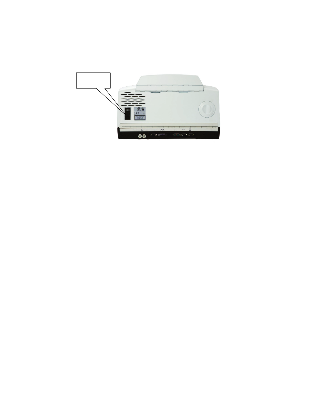
Power switch and communication ports
The power switch, AC power cable connector, and communications ports are on the rear of
the instrument. The power switch is marked I/O (on/off).
NOTE: It can take the instrument about two hours to equilibrate when switched on after
being switched off overnight. To save time, we suggest that you leave the instrument
switched on at all times.
Page 30

30 . Frontier IR Single-range Spectrometers User's Guide
Accessories
A wide range of optional accessories, such as the Universal ATR accessory (UATR), fits in the
sample compartment. In addition, a number of external accessories are available, including
the External NIRA. An external accessory can be fitted in conjunction with another internal
accessory.
Table 1 Sampling accessories for the Frontier IR instruments
Accessory MIR NIR
Sample Shuttle Yes Yes
Horizontal ATR Yes n/a
Universal ATR Yes n/a
Diffuse Reflectance Yes n/a
NIRA n/a Yes
External NIRA n/a Yes
NIR Fiber Optic Probe n/a Yes
NIR Tablet Autosampler* n/a Yes
Liquid Sipper* Yes Yes
TL 8000 EGA System (TG-IR) Yes Yes
General Purpose Optical Bench (GPOB) with External
MCT Detector**
General Purpose Optical Bench (GPOB) and External
LiTaO
*The Liquid Sipper and NIR Tablet Autosampler accessories are supported by AssureID software and
Spectrum software version 6.x. They are not supported in Spectrum software version 10.0 or later.
** For more details of the GPOB options, contact your PerkinElmer Sales Representative.
Further information about the use of these accessories can be found on the
Manuals CD
Detector**
3
(L1050002).
Yes Yes
Yes Yes
IR & Raman
Page 31

An Overview of the Frontier IR Single-Range Spectrometers . 31
Frontier IR Systems Upgrades
The Frontier IR systems as designed to be flexible, upgradable instruments, including the
ability to upgrade from a single-range to a dual-range instrument. The upgrades available for
Frontier IR Single-Range Systems are listed in Table 2.
Table 2 Frontier IR Single-Range Systems Upgrades
Part Number Description
L1280247 Performance Pack Upgrade – DTGS detector upgrade
L1280248 External Pack Beam Upgrade – Microscope, GPOB, NIRA and
external beam input port ready
The kit contains KBr windows, but other windows are available. Ask
your PerkinElmer Customer Service Representative for details
L1280258 Single-Range FT-IR to Dual-Range FT-IR/FT-NIR upgrade
L1280259 Single-Range FT-NIR to Dual-Range FT-IR/FT-NIR upgrade
L1280260 Single-Range FT-IR to Dual-Range FT-IR/FT-FIR upgrade
L1280249 Narrow band 1 mm MCT FT-IR Second Detector
(adds an MCT detector in the second detector position)
FT-IR instruments only
L1280250 Medium band 1 mm MCT FT-IR Second Detector
(adds an MCT detector in the second detector position)
FT-IR instruments only
L1280251 Wide band 1 mm MCT FT-IR Second Detector
(adds an MCT detector in the second detector position)
FT-IR instruments only
L1250477 ZnSe Window Upgrade Kt
(optional ZnSe window for Single-Range FT-IR instruments)
L1200391 Electronic Humidity Sensor
Page 32

32 . Frontier IR Single-range Spectrometers User's Guide
Page 33

Unpacking and
Installation
Page 34

34 . Frontier IR Single-range Spectrometers User's Guide
Requirements
NOTE: Read the warnings and safety information at the start of this manual before you
install the instrument. They contain important information.
Electrical requirements
The Frontier IR instruments can operate on electricity supplies of 50 or 60 Hz and in the
100 V to 230 V range without any adjustment.
The nominal power consumption of the instrument is 120 VA.
The line supply must be within 10% of the nominal voltage.
If possible, do not connect the instrument to circuits that have heavy duty equipment
connected, such as large motors.
If possible, do not use photocopiers, discharge lamps, radio transmitters, and other
equipment with large or frequent transient loads on the same supply circuit.
The primary fuse (2 AT, 250 V) is in the drawer on the rear of the instrument next to the
mains inlet: the spare fuse is in the same drawer. The primary fuse is connected in the live
line.
Environment
To obtain the best performance from your instrument:
• Place the instrument in an environment that is relatively dust-free.
• Make sure that the bench top is free from vibration or mechanical shocks.
• Do not place the instrument or the PC near to room-heating equipment, such as
central-heating radiators.
• Do not position the instrument in direct sunlight, as this may cause overheating.
• Leave at least 15 cm (6 inches) from any surface and the cooling louvers at the rear of
the instrument.
• Leave at least 7 cm (3 inches) from any vertical obstacle to the sides of the instrument,
to permit an adequate flow of cooling air.
• Make sure that there are no overhanging shelves, and no water pipes or faucets that
could leak onto the instrument.
• The area near the PC must be free of strong magnetic fields, direct sunlight, and heating
or cooling units or ducts.
The instrument has been designed for indoor use and operates correctly under the following
conditions:
Ambient temperature 15 °C to 35 °C
Ambient relative humidity 80% maximum (non-condensing)
Page 35

Unpacking the Spectrometer
The spectrometer is a heavy precision instrument, so two people are
required for safe handling.
The instrument weighs approximately 34 kg unpacked (40 kg packed)
and has a lifting recess on either side. Consult the local codes of practice
WARNING
CAUTION
issued by safety advisors before attempting to lift it.
Take care not to injure yourself or others, or to drop the instrument.
Take great care when installing your Frontier IR spectrometer, and
follow the procedures described in this manual. If you require assistance,
contact your local PerkinElmer Service Engineer.
Unpacking and Installation . 35
Opening the shipping container
Your spectrometer is packed inside the box in a silver bag that protects it from condensation.
1. First remove the software box, leads, and so on from the box, and check that all the
following parts are present:
Part Number Description MIR NIR
L1202057 Polystyrene Calibration Film 1 –
L1180479 NIR Performance Validation Kit – 1
04974265 Quick Release Purge Coupling 2 2
L1200466 Ethernet Crossover Cable 1 1
04790839 2 A, 250 V Time Lag Fuse 2 2
09923433 8.0 mm Hexagonal Wrench 1 1
L1050002 IR & Raman Manuals CD 1 1
L1250230 Spectrum Configuration Disk 1 1
LX108873
OR
LX108875
L1240055 Cuvette Holder Assembly – 1
L1240056 Cell Holder Assembly & Disposable Cells (5) – 1
If any items are missing or damaged, contact your local PerkinElmer office.
Spectrum Standard Software Kit
OR
Spectrum ES Software Kit
1 1
Page 36

36 . Frontier IR Single-range Spectrometers User's Guide
2. Carefully remove the instrument from the shipping container, but not from the bag in
which it was shipped.
The spectrometer must be allowed to reach the temperature of its
CAUTION
surroundings before it is removed from the bag. This means leaving it
overnight if it has been moved from a cold area, and at least 4 hours
after removal from the shipping container.
3. When the spectrometer has been allowed to warm to the temperature of its
surroundings, remove it from the bag and place it on the bench where it is to be used.
Ensure that you can reach the rear of the spectrometer to connect the cables.
NOTE: Any accessories will be shipped in separate boxes.
Page 37

Unpacking and Installation . 37
must
Pink
Blue
Blue
The Desiccant Indicator
The optical system of the spectrometer is purged at the factory. This protects the
beamsplitter and the sample compartment windows from being damaged by humidity.
Replaceable packs of desiccant keep the optics dry and free of CO
The top panel of the instrument includes a desiccant indicator, whose sectors change
sequentially from blue to pink as the desiccant packs are exhausted (Figure 10). Change the
desiccant in the instrument when the sector marked 10 becomes pink, but while the sectors
marked 15 and 20 are still blue.
.
2
Refer to
appropriate action to take if the sectors marked 15 and 20 are pink.
Figure 10 The desiccant indicator
The Desiccant Indicator in Detail
on page 56 for more information about the
If all three sectors of the desiccant indicator are pink, then you
change the desiccant.
CAUTION
The instrument optics may be fogged. Do not switch the instrument
either ON or OFF until all sectors are blue.
Page 38

38 . Frontier IR Single-range Spectrometers User's Guide
PC or network
connection port
Connecting up the Spectrometer
Connecting to the PC
NOTE: To control your instrument from a PC, use the crossover cable supplied.
To control your instrument over your network, use a standard Ethernet cable (not
supplied).
1. Plug one end of the cable into the connector port on the right-hand side of the
instrument (Figure 11).
Figure 11 PC connection port
2. Plug the other end of the cable into the network connection on your PC (if you are using
the crossover cable) or network hub (if you are using a standard Ethernet cable).
Connector details
Description Connector
Type
10/100 Base-T Ethernet connector. This is the
standard interface between the PC and the
instrument, or between a Local Area Network
(LAN) and the instrument. If connecting directly
from the PC to the instrument use the Category 5
UTP Cross-Over cable supplied. If you are
connecting to your network, use a standard
Ethernet cable.
DO NOT USE THE CROSS-OVER CABLE TO
CONNECT TO YOUR NETWORK.
Ethernet <5 V <100 mA
Voltage Maximum
Current
Page 39

Unpacking and Installation . 39
Sample area purge
Instrument purge
10101
Spt. Lt.
EXT.R
Other connectors
The communication ports for peripheral devices are shown in Figure 12.
Figure 12 Communication ports
Icons that identify the function of each of the communications ports are printed on the hinge
molding directly above the port.
Connector details
Icon Description Connector
Type
10101
Spt.Lt
Serial port. Connects a PC to the
instrument using an RS232
interface cable. This connector is
only used for service diagnostics.
General Purpose Optical Bench
(GPOB). Allows synchronization
between the instrument and an
external accessory.
Spotlight. Used to connect the
instrument to a Spotlight Imaging
System.
9-way
D-type
26-way
high density
D-type
11-way
mixed
D-type
Voltages Maximum
Currents
+12 V <100 mA
−12 V <100 mA
+5 V <50 mA
+5 V <100 mA
±12 V 50 mA
Page 40

40 . Frontier IR Single-range Spectrometers User's Guide
Icon Description Connector
Type
EXT.R
Right external detector module.
Connects to an external detector
module. Usually the detector is
located in an accessory placed on
the right of the instrument.
Microscope external detector
module. Connects to a
PerkinElmer infrared microscope,
placed on the left of the
instrument.
15 way
high density
D-type
15 way
high density
D-type
Voltages Maximum
Currents
+12 V 0.65 A
−12 V 0.65 A
+5 V 4 A
+12 V 0.65 A
−12 V 0.65 A
+5 V 4 A
Do not attempt to connect a monitor to either the EXT.R port or the
CAUTION
MICROSCOPE port or you will cause serious damage to the instrument
when it is switched on.
Connecting the spectrometer to the electrical supply
The power cable for the electrical supply plugs into the rear of the instrument. It has a
molded socket at one end. If it is necessary to fit a plug on the power cable, use the wire
color code below:
Plug Pin Wire Color (100–120 V) Wire Color (220–240 V)
Ground (Earth) Green or Green/Yellow Green/Yellow
Live Black Brown
Neutral White Blue
To ensure safe and satisfactory operation of the instrument, it is
essential that the green or green/yellow ground (earth) wire of the
power cord is connected to a ground that complies with the regulations
WARNING
of the local electricity supply authority (or equivalent body); ground
circuit continuity is essential for safe operation of the equipment.
Page 41
Unpacking and Installation . 41
Electricity
supply inlet
Frontier IR instruments can operate on electricity supplies of 50 Hz or 60 Hz and in the 100 V
to 230 V range without any adjustment.
1. Fit the molded socket of the power cable into the electrical supply inlet (Figure 13) of
the instrument.
Figure 13 Electrical supply inlet
2. Switch on the power at the supply.
3. Switch on the instrument at the switch above the supply inlet.
I is on and O is off.
After a short diagnostic check, which takes about 2 minutes and is described in
Instrument Self-Checks
on page 90, your instrument will be ready to communicate with the
PC.
Appendix 2:
Page 42

42 . Frontier IR Single-range Spectrometers User's Guide
Installing the Instrument in the Software
Before you can use the instrument it must be set up in the software.
Installing the software
NOTE: If you are supplying your own computer, make sure that it meets the minimum
requirements for hardware and software set out in the “PC Requirements” section of
the
Administrator’s Guide
Manuals CD
To install Spectrum software, insert the supplied DVD and follow the instructions on the
screen. Details of the installation program are given in the
(part number L1050002) supplied with your instrument.
The Instrument Install Wizard
After installing your software you will need to install your instrument.
If you have Spectrum software or Spectrum ES software, select Add Instrument from
the Administration group on the Setup menu.
The Instrument Install Wizard starts.
for your software, which can be found on the
Administrator’s Guide
IR & Raman
.
OR
If you have AssureID software, select Configure Instruments from the Configure
Instruments and Accessories group on the Tools menu.
The Instrument Install Wizard starts.
Details of the Instrument Install Wizard can be found in the
software, which can be found on the
supplied with your instrument.
IR & Raman Manuals CD
Administrator’s Guide
(part number L1050002)
for your
Page 43

Using the Spectrometer
with Spectrum
Page 44
44 . Frontier IR Single-range Spectrometers User's Guide
Basics of Software Control
Starting Spectrum software
1. Switch on the power to the instrument using the switch on the rear of the instrument.
The instrument will initialize, which will take approximately 2 minutes.
NOTE: It can take the instrument about two hours to equilibrate when switched on after
being switched off overnight. To save time, we suggest that you leave the instrument
switched on at all times.
2. From the Start menu select Programs; the PerkinElmer Applications group; the
Spectrum sub-group and then the Spectrum application.
OR
Double-click the shortcut icon on the desktop.
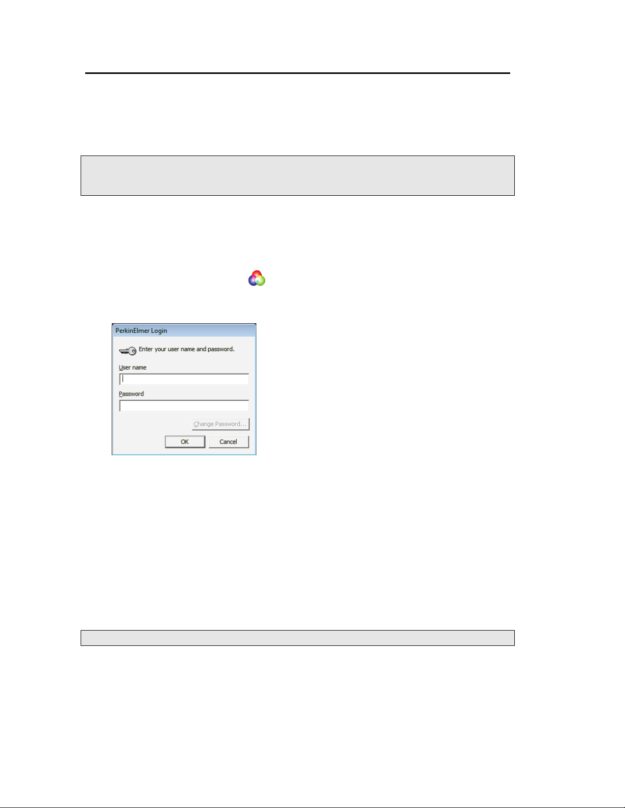
The Spectrum start-up splash-screen is displayed, followed by a dialog that may require
your login details:
3. If required, enter your User name and Password, and then click OK.
If you already have an instrument set up in Spectrum or AssureID software for this user
on this PC, the Instrument Connection dialog may be displayed, unless Auto Connect is
set up for the instrument. If Auto Connect is enabled Spectrum will automatically
connect to the instrument.
4. Select the Instrument you want to use.
OR
If you want to work with data that has been collected previously, without connecting to
an instrument, select work offline.
NOTE: Working offline can free a networked instrument for use by another user.
Spectrum starts.
Page 45

Using the Spectrometer with Spectrum . 45
Scanning samples
When you connect to your spectrometer the instrument settings will default to appropriate
values for your instrument type and accessory.
The configurable Scan toolbars at the top of the workspace include the tools you need to
collect a sample spectrum (Figure 14).
Figure 14 Frontier IR Single-Range systems default scan toolbars
By default, the Measurement bar includes Scan, Halt, Background and Monitor buttons.
You can also select Scanalyze and then choose one of the scan and then process options
Scan and Compare, Scan and Search or Scan and Quant. All these commands can be
selected from the Measurement menu.
NOTE: The Scan toolbars are not displayed if you have chosen to work offline.
To scan a sample:
1. Check and set the instrument parameters.
Here you set the Start and End points of the scan range (by default in wavenumbers,
but the abscissa units can also be set to nanometers or microns on the Setup
Instrument Basic tab) and the Accumulations required, either as a number of scans,
or as a length of time. You can enter a unique Sample ID and Description for the
sample. You can also set the Resolution (in cm
(in mm) to the default for that resolution, which you can then edit.
By default, sensible values for the scan and instrument parameters are entered in the
Instrument Settings toolbar. The values applied depend on your instrument and
accessory. To amend any value, select the parameter and then enter your new value, or
select a value from the drop-down list.
2. If a background scan is required, the Scan button includes a small background flag.
Clear the instrument beam path, or insert a suitable background material, and then click
to collect a background spectrum.
The background spectrum is displayed briefly, and then the Viewing Area is prepared
for data collection from your sample.
We recommended that you run a background scan before every sample.
NOTE: If you wish to run a background scan with a filter in place, you must set the Scan
Type to Background on the Setup Instrument Basic tab, rather than using the
toolbar button. See the Spectrum on-screen Help for more information.
−1
). This will set the J-Stop size
3. Place your sample in the instrument or accessory and then click to begin scanning
your sample.
By default, during scanning the sample data is displayed on the Live tab in the Viewing
Area.
The completed spectrum is displayed on the Graph tab, and added to the current
Samples View in the Data Explorer.
4. If, for any reason, you want to stop scanning your sample, click .
Page 46

46 . Frontier IR Single-range Spectrometers User's Guide
Display
Go button
You can use the Sample Shuttle Accessory (L1200302) to set up an interleaved cycle scan so
that you do not have to open the sample compartment between the background and sample
scans. This helps to reduce changes in the concentration of carbon dioxide and water vapor
in the sample compartment. Set the Scan Type to Interleaved on the Setup Instrument
Basic tab. See the Spectrum on-screen Help for more information.
Working with the instrument display and Go button
The display on the top of your instrument is used to display prompts and other messages
generated by Spectrum software.
Simply follow the prompts in the instrument display and use the Go button located on the
instrument to complete a series of sample scans.
Figure 15 Top panel controls
Changing the beam path
Hover over the icons on the Setup Instrument BeamPath tab to identify elements in the
instrument beam path. As you click on each item, the appropriate row in the Settings Table is
highlighted.
The accessory fitted in the sample compartment is identified by a graphic element in the
beam path schematic. If an external accessory is fitted at the beam port on the right of the
instrument, or a Spotlight Imaging System is fitted, the Setup Instrument BeamPath tab
includes additional elements that enable you to redirect the beam path to the accessory you
want to use.
Page 47

Using the Spectrometer with Spectrum . 47
In Figure 16 the beam path is directed to the standard sample slide. In this example, the
additional interface elements for the Spotlight microscope are also shown.
Figure 16 Setup Instrument BeamPath tab with the beam path directed to the
Slide Holder
To direct the beam to the Spotlight microscope, select Left external from the Beam
Location drop-down list.
Figure 17 Setup Instrument BeamPath tab with the beam path directed to the
Microscope (circled)
Using the Spectrum on-screen Help system
Use the Spectrum Help system to find further information about using Spectrum software to
control, set up and adjust your instrument.
To open the Help file, select Contents from the Help menu. This menu also includes links to
on-screen tutorials (Tutorials), and information about the software (About).
Page 48
48 . Frontier IR Single-range Spectrometers User's Guide
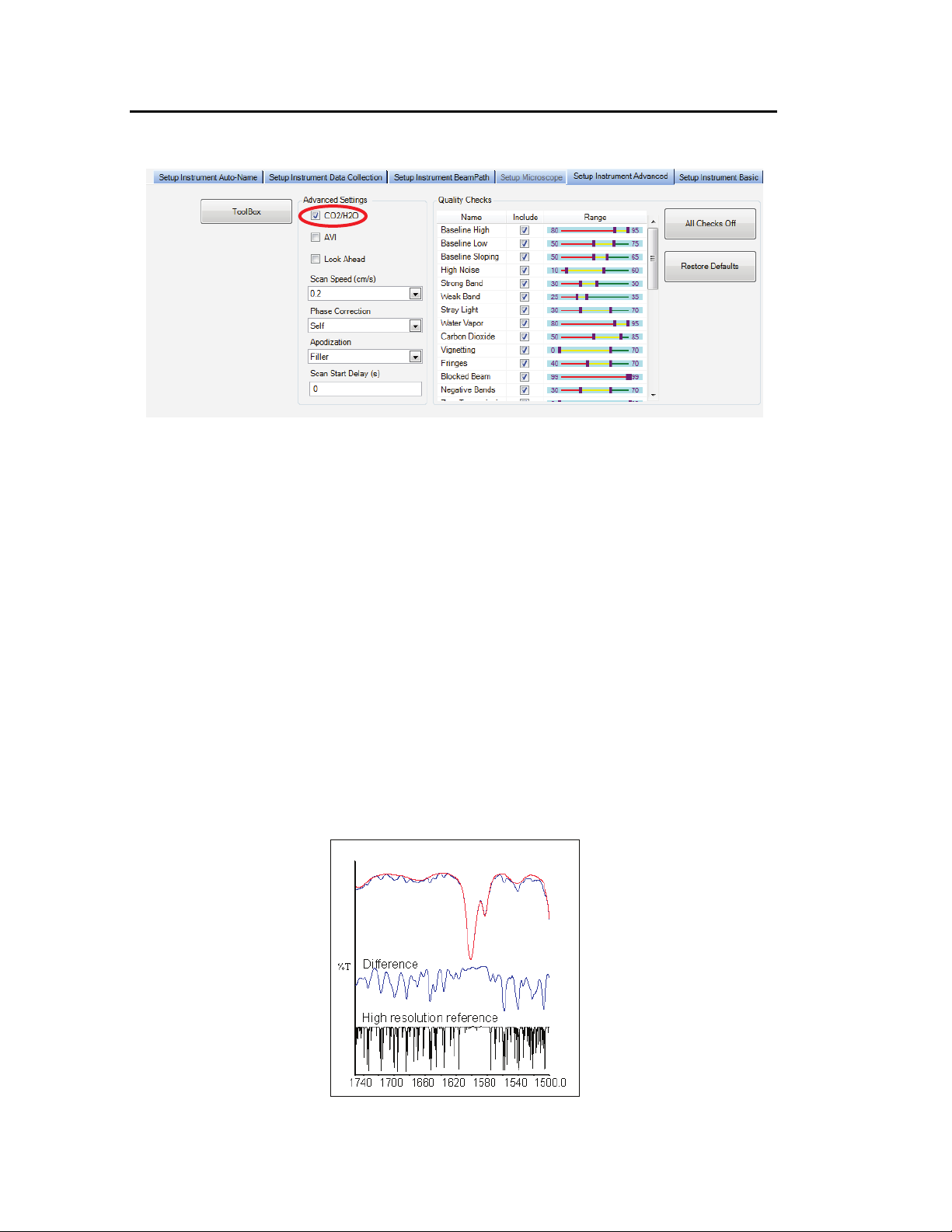
Atmospheric (CO2/H2O) Suppression
Atmospheric suppression can be selected in the Setup Instrument Advanced tab (Figure 18).
Figure 18 Setup Instrument Advanced tab in Spectrum
What is atmospheric suppression?
This is an atmospheric correction routine. This routine is more powerful than simple
subtraction, overcoming the following issues:
• Non-linearity due to resolution
• The measured spectrum is temperature dependent
• Lineshape and calibration are affected by J-stop and sample or accessory.
What does atmospheric suppression do?
When CO2/H2O is switched on, the software uses a single reference spectrum derived from
high resolution data and our understanding of the instrument to model the lineshape, then
finds the current real instrument parameters by least squares fitting to the measured
spectrum.
Figure 19 Correction of an MIR spectrum at 4 cm
−1
resolution
Page 49

Using the Spectrometer with Spectrum . 49
Figure 20 Atmospheric suppression
Page 50

50 . Frontier IR Single-range Spectrometers User's Guide
AVI Correction
AVI correction can be selected in the Setup Instrument Advanced tab in Spectrum
(Figure 18).
AVI correction can only be performed if an AVI Calibration has been set up for the current
configuration and resolution. Select AVI from the Adjustments Toolbox, available from the
Setup Instrument Advanced Tab. Follow the instructions on-screen. For further information,
refer to the Spectrum on-screen Help file.
NOTE: AVI correction uses a methane gas cell installed in the filter wheel.
What is AVI correction?
The objectives of Absolute Virtual Instrument (AVI) correction are:
• Consistent performance over time and between instruments
• Traceability for all measurements.
Although FT-IR spectrometers use a reference laser, the wavenumber calibration and
lineshape are affected by differences in beam divergence and uniformity. This is true for all
FT-IR spectrometers. Differences can occur between instruments, when using different
sampling accessories and when components are changed. AVI allows calibration and
lineshape to be maintained.
The Absolute Virtual Instrument is an instrument with theoretical performance, such that the
result of measuring a known sample on such an instrument can be predicted. So, if we
measure with a real instrument and calculate the software transform to match the theoretical
result, we can apply this transform to future measurements.
The Absolute Virtual Instrument is defined by wavenumber calibration, instrument lineshape
and ordinate accuracy.
What does AVI correction do?
When AVI is switched on, the software measures the current instrument profile relative to an
absolute standard (the methane cell) and an ideal lineshape function, and applies a
correction (Figure 21). If you have an automated, internal filter wheel, this can provide
correction for any sampling configuration.
Figure 21 Spectra of methane at 4 cm
AVI (bottom)
−1
resolution as measured (top) and with
Page 51

Using the Spectrometer with Spectrum . 51
Look Ahead
Look Ahead can be selected in the Setup Instrument Advanced tab (Figure 18).
What is Look Ahead?
Look Ahead is a novel system where the spectrometer scans continuously and uses the
properties of the measured spectrum to identify changes corresponding to sample removal,
sample insertion, or sample change, automatically.
This information is used to identify the scans that are being collected, and to accumulate
sample scans. This can decrease the overall scanning time required for those samples that
require scan accumulation.
What does Look Ahead do?
If Look Ahead has been enabled, the spectrometer scans continuously. When you request a
sample scan, the scan collected is compared to the scans that have already been collected. If
identical scans are found, the number of scans requested is decreased by the number of
scans found, so decreasing the overall scanning time.
Page 52

52 . Frontier IR Single-range Spectrometers User's Guide
Quality Checks
Quality Checks can be selected in the Setup Instrument Advanced tab (Figure 18).
What are Quality Checks?
Quality checking is a tool for less experienced IR users that identifies possible problems in
the spectrum being collected and suggests ways of improving the measurement.
What do Quality Checks do?
Simply select the Quality Checks that you want to perform from the list in the Setup
Instrument Advanced tab and, if required, adjust the threshold range using the slider bars.
To display more information about an individual test, double-click on its name in the list.
When you collect your spectrum, the selected tests are performed as the data is collected
and a signal light (green , amber , or red ) indicates the result.
The results from the Quality Checks imply:
Okay ( ) – the quality of the spectra is satisfactory.
Caution ( ) – the software has identified a problem that you may want to investigate in
order to improve the quality of the spectra you are collecting.
Warning ( ) – the software has identified a serious problem that you should attempt to
cure before collecting further spectra.
Page 53

Routine Maintenance
Page 54

54 . Frontier IR Single-range Spectrometers User's Guide
Cleaning the Spectrometer
Clean the outside of the instrument using a damp cloth. If necessary, a mild detergent may
be used. Before you clean the entire instrument, always perform a patch test on an
inconspicuous area.
Avoid spilling liquid into the instrument. Clean all external spills immediately. If anything that
is spilled enters the main body of the spectrometer, switch off the power and contact a
PerkinElmer Service Engineer.
Do not touch or attempt to clean any optical surface in the instrument,
CAUTION
Cleaning the display
Clean grease and dirt off the display using a soft damp cloth and a mild detergent.
because this will impair its performance and may easily damage the
component.
Page 55

Routine Maintenance . 55
Lifting handhold,
Moving the Spectrometer
The spectrometer is a heavy precision instrument, so two people are
required for safe handling.
WARNING
WARNING
The spectrometer can be lifted using the shaped handholds on its sides, as shown in
Figure 22. Two people are needed to lift it because its basic weight is approximately 34 kg.
Consult the local codes of practice issued by safety advisors before
attempting to lift it.
Take care not to injure yourself or others, or to drop the spectrometer.
Before moving the spectrometer, switch off the power supply, wait
60 seconds, and disconnect the power cable.
(repeated on left
of the instrument)
Figure 22 Lifting a Frontier IR spectrometer
Condensation
Be aware that condensation caused by moving your spectrometer from a cooler environment
to a warmer one can damage the windows of the sample compartment. To prevent this
damage from occurring:
• Make sure that the windows are protected by placing fresh bags of desiccant in the
sample compartment.
• Leave the spectrometer to reach the temperature of the surroundings before removing
the desiccant.
Page 56

56 . Frontier IR Single-range Spectrometers User's Guide
must
Desiccant change is recommended.
Pink
Blue
Blue
The Desiccant Indicator in Detail
The optical system of the spectrometer is purged at the factory. This protects the KBr (or
) beamsplitters, sample compartment windows, or external port windows from being
CaF
2
damaged by humidity. Replaceable packs of desiccant maintain the purge.
The top panel of the instrument includes a desiccant indicator (Figure 23), whose sectors
change sequentially from blue to pink as the desiccant becomes exhausted. Change the
desiccant packs in the instrument when the sector marked 10 becomes pink, but while the
sectors marked 15 and 20 are still blue. These numbers correspond to the approximate
% Relative Humidity in the instrument.
Figure 23 The desiccant indicator: when desiccant packs should be changed
If all three sectors of the desiccant indicator are pink, then you
CAUTION
the desiccant.
The instrument optics may be fogged. Do not switch the instrument either ON
or OFF until all sectors are blue.
Sector Action Required
All sectors blue None.
The humidity levels in the instrument are below approximately 10%
Relative Humidity.
Sector 10 pink
If the instrument has been switched OFF for an extended period, do not
switch ON until you have changed the desiccant and all sectors are
blue.
Sector 10 & 15
pink
Replace desiccant the immediately to avoid instrument damage.
Do not switch the instrument ON or OFF until you have changed the
desiccant and all sectors are blue.
change
Page 57

Changing the Desiccant
Routine Maintenance . 57
CAUTION
Expect to change the desiccant
Old, used desiccant releases moisture.
in the
spectrometer every six months.
In regions experiencing high humidity levels we recommend that you
change the desiccant more often.
The desiccant change interval is set in the Desiccant change due in (days) option on the
Setup Instrument BeamPath tab in Spectrum software (Figure 24).
Figure 24 Setup Instrument BeamPath tab in Spectrum
If an instrument desiccant change is overdue, a warning will be displayed in the Status Bar
and in the Setup Instrument BeamPath table.
The warning is displayed until you tell the software that the desiccant has been changed. To
reset the desiccant change interval, select the current value, click Changed to clear any
warning messages, and then enter the number of days before the next desiccant change is
due.
Page 58

58 . Frontier IR Single-range Spectrometers User's Guide
Screw
Screw
Sample cover
Renewing the instrument desiccant
Old, used desiccant releases moisture and can cause catastrophic failure
CAUTION
You can purchase disposable desiccant kits from PerkinElmer (part number N0171159). A kit
contains two packs of desiccant, and three kits are required.
1. Inspect the humidity indicator card in the plastic bags in which the spare desiccant
packs are packed. If the card indicates humidity in the bag, discard the desiccant pack.
2. Remove the sample area cover, if fitted, by opening the cover, pressing the clip and
pulling the cover vertically to remove (Figure 25).
of KBr optics.
Do not use damaged packs of desiccant. Make sure that the packs you
use have not been left in contact with the air.
release clip
Figure 25 Removing the sample compartment cover
3. Undo the two captive screws securing the desiccant cover (Figure 26).
Figure 26 Captive screws securing the desiccant cover
Page 59

Routine Maintenance . 59
Desiccant
4. Open the cover and remove all the exhausted desiccant packs (Figure 27), noting how
they are installed.
compartment
(empty)
Figure 27 Desiccant removed
5. Place the first three packs of desiccant upright in the recess on the right of the
desiccant holder then, one at a time, lay the three remaining packs flat in the upper
part of the holder (Figure 28).
Figure 28 Stowing the desiccant packs
Ensure that when the packs have been installed they do not rise above the level of the
black rubber purge seal.
6. Close the cover and tighten the screws.
7. Refit the sample area cover.
Installing rechargeable desiccant in the instrument
There is also a rechargeable desiccant kit available (part number L1250311).
To install rechargeable desiccant packs follow the
procedure starting on page 58.
The instrument requires two rechargeable desiccant packs; the packs are sized to fit into the
left (70 mm × 78 mm × 33 mm) or right (102 mm × 78 mm × 84 mm) of the desiccant
container.
The standard kit contains two pairs of rechargeable desiccant packs. This is so you can
immediately replace the desiccant in the instrument with re-activated packs.
Renewing the instrument desiccant
The desiccant packs can be re-activated by baking them in an oven at 250 °C for
approximately 8 hours. They should be cooled in a dry atmosphere. For optimum results,
re-activate the packs immediately before re-use.
Page 60

60 . Frontier IR Single-range Spectrometers User's Guide
Purging the Spectrometer
Under most circumstances, you do not need to purge the optical system. However, after
performing any maintenance tasks that involved opening the main cover, you may purge the
optical system to remove water vapor and CO
that entered while the system was open.
2
Purge the sample compartment if you need to make sure that no residual water vapor or CO
peaks are visible in the spectrum.
There are two separate sets of connectors for purge gas lines, one for the sample
compartment and one for the optical system. You can purge with either dry air or nitrogen.
Both remove water vapor; however, nitrogen is preferable because it also removes
atmospheric carbon dioxide.
3
A typical cylinder of dry nitrogen (or dry air) stores 6.26 m
2200 lbf/in
2
). Make sure that the gas is free of oil, water, or dirt particles larger than 25 µm
at 1.4 × 10⁴ kPa (220 ft3 at
(0.001 inch).
Do not site the instrument in a poorly ventilated area if nitrogen will be
used as a purge gas.
WARNING
Oxygen depletion in an enclosed space does not trigger a gasping reflex,
and errors of judgment, confusion, or unconsciousness can occur in
seconds and without warning.
Do not use a flammable gas to purge the instrument. The spectrometer
contains a hot source, and a fire or explosion will result. Only use clean,
dry, oil-free nitrogen or air to purge the instrument.
WARNING
2
Never connect the purge tubing directly to a gas cylinder or other high
pressure supply; always use a pressure regulator and set the pressure to
a maximum of 1 lbf/in
2
(6.9 kPa) before you start the flow.
WARNING
A length of clear plastic tubing (4 mm internal diameter) will be required to transfer the gas
from the gas bottle to the instrument purge connectors.
Page 61

Routine Maintenance . 61
Instrument purge
Sample purge
Beveled end of
connector
Knurled nut
Tubing
1. The tubing is connected to the instrument by a universal pipe fitting which is secured to
the tubing with a nut. Two sets of fittings are supplied with the instrument. Assemble
the fittings to the tubing as illustrated in Figure 29.
Figure 29 Purge fittings
2. Tighten the nut, ensuring it is not over tightened.
3. Push the connector on the end of the tubing into the purge connector of the
compartment to be purged (Figure 30).
If the connector will not push in, press the clip at the bottom of the port and try again.
Figure 30 Connector fitted to purge port
4. Connect the free end of the tubing to the gas regulator.
NOTE: Ensure the regulator is set to a pressure not greater than 6.9 kPa (1 lbf/in2).
5. Open the gas flow valve on the regulator until a flow rate of 28 l/minute (1 ft3/minute)
is achieved.
The instrument compartment is purged in 10 minutes. The sample compartment is
purged in 2 minutes.
6. Once purging is complete turn off the gas supply.
Page 62

62 . Frontier IR Single-range Spectrometers User's Guide
Locking clip
7. Disconnect the fitting from the instrument by pushing the clip located at the bottom of
the purging port (Figure 31).
Figure 31 Disconnect the locking clip
Page 63

Routine Maintenance . 63
Fuse drawer
Changing the External Fuse
Very occasionally, a fuse may fail with age and will need to be changed.
NOTE: If fuses fail repeatedly, there is an electrical fault: disconnect the power supply and
contact your PerkinElmer Service Engineer.
There is one spare fuse in the fuse drawer. If you need more, order 2A, 250V Time Lag fuses
(part number 04970839) from PerkinElmer. You must only replace the fuse with one of this
type and rating. Do not use makeshift fuses and do not short-circuit fuse holders.
Before you begin this procedure, switch off the power to the
spectrometer, wait for 60 seconds, and disconnect the power cable.
WARNING
The external fuse drawer is located at the rear of the instrument between the power switch
and the power socket (Figure 32).
This will protect you from electrical shock.
Figure 32 Fuse drawer closed
Page 64

64 . Frontier IR Single-range Spectrometers User's Guide
Spare fuse
Fuse
Fuse drawer
1. Lever out the fuse drawer so that it swings down over the power socket.
The fuse is in the right hand slot.
2. Remove the old fuse and discard it.
3. Fit the new fuse into the slot (Figure 33).
Figure 33 Fuse fitted; drawer open
4. Close the drawer.
The new fuse is now installed.
5. Reconnect the power cable and switch on the instrument.
Page 65

Routine Maintenance . 65
replacing the plug. This enables the bubbling nitrogen to settle down and
Cooling the MCT Detector (If Fitted)
Optionally, the Frontier FT-IR may be fitted with an MCT (mercury cadmium telluride)
detector. When it is fitted in the instrument it must be cooled to 77 K before you collect
spectra. The detector is mounted in a dewar that can be filled with liquid nitrogen. The
detector is not enabled until it has been sufficiently cooled.
Do not site the instrument in a poorly ventilated area if liquid nitrogen
will be used to cool a detector.
WARNING
WARNING
Oxygen depletion in an enclosed space does not trigger a gasping reflex,
and errors of judgment, confusion, or unconsciousness can occur in
seconds and without warning.
The extremely low temperature of liquid nitrogen can burn skin and
eyes. Avoid exposure by wearing protective gloves and safety goggles
whenever you work with it.
WARNING
WARNING
As liquid nitrogen cools the detector it evaporates so rapidly that the
resulting pressures can send a funnel or detector cap suddenly and
forcefully shooting upward from the top of the dewar.
Be sure to wait the specified time when filling the funnel and before
the pressure to dissipate. In addition to wearing safety goggles at all
times, stand back from the instrument after each time you fill the funnel.
Page 66

66 . Frontier IR Single-range Spectrometers User's Guide
MCT coolant cover
1. Remove the MCT coolant cover (Figure 34).
Figure 34 Location of MCT coolant cover
2. Remove the plug from the dewar.
3. Ensure that the funnel guide, which helps prevent overspill entering the instrument
body rather than the dewar, is in place.
4. Make sure the supplied plastic funnel is dry.
Stand where you can see the inside of the funnel as you pour the
CAUTION
nitrogen in. Pour slowly, so that neither the funnel nor the dewar
overflows. Take care not to overfill the funnel and splash liquid nitrogen
onto the instrument covers.
5. Insert the plastic funnel into the funnel guide and slowly fill the detector dewar with
liquid nitrogen.
NOTE: Make sure that the detector dewar is filled to the top with liquid nitrogen before
selecting the detector. Prevent radiation from reaching the detector by obstructing
the beam path in the sample area during filling.
6. Stand back and wait two minutes.
This nitrogen also vaporizes as the dewar continues to cool. The two-minute wait allows
the bubbling to settle down and the pressure of the vaporizing nitrogen to dissipate.
7. Continue to pour liquid nitrogen into the funnel, adding a little more each time the
funnel empties.
The funnel takes longer to empty as the dewar fills. This happens after two or three
more funnels of liquid nitrogen. Because the dewar has now cooled, the liquid nitrogen
does not vaporize, but instead fills the dewar.
8. Remove the funnel and wait two minutes.
The liquid nitrogen settles down and bubbling slows.
Page 67

Routine Maintenance . 67
9. When the nitrogen stops bubbling, refit the plug.
When the detector dewar has been filled, it will remain at its operating temperature for
approximately eight hours.
NOTE: Cooled detector dewars require pumping down after approximately 12 months
operation. When the boil-off rate of liquid nitrogen becomes excessive (that is, the
liquid nitrogen level is low after 3–4 hours of operation), consult your PerkinElmer
Service Engineer.
Page 68

68 . Frontier IR Single-range Spectrometers User's Guide
Page 69

Advanced Maintenance
Page 70

70 . Frontier IR Single-range Spectrometers User's Guide
Locking bolt
Locking bolt
Opening the Main Cover
To perform most maintenance tasks, you have to open the main cover of the spectrometer.
NOTE: If you have any samples or reference materials in the storage compartment, you are
advised to remove these before opening the main cover.
Switch off the mains power supply to the spectrometer, wait 60 seconds
and disconnect the power cable before you open the cover of the
spectrometer. This makes sure that you are safe from electrical shock
WARNING
CAUTION
and laser radiation.
Do not open the main cover if the humidity is:
>80% relative humidity for an instrument fitted with KBr optics.
>45% relative humidity for an instrument fitted with CsI optics.
The humidity sensitive optics will be damaged if subjected to a relative
humidity in excess of the specified levels.
The main cover is hinged at the back of the instrument and opens from the front. Figure 35
identifies the locking bolts, which are on the front of the instrument.
Figure 35 Main cover locking bolts
1. Switch off the power supply to the spectrometer.
2. Wait for 60 seconds.
3. Disconnect the power cable.
4. Remove the sample compartment cover, if fitted; open the cover, press on the cover
retaining clip and then pull the cover vertically to remove it (Figure 36).
Page 71

Advanced Maintenance . 71
Sample cover
release clip
Sampling accessory
Figure 36 Removing the sample compartment cover
5. Remove the fitted sampling accessory, by pulling the release handle towards you and
sliding the accessory towards you (Figure 37).
release handle
Figure 37 Removing the sampling accessory
6. Undo the two locking bolts on the front of the instrument using the hexagonal wrench
supplied; insert the wrench, so that the free end is pointing horizontally away from the
instrument and then rotate the wrench 180° in the direction indicated by the arrows in
Figure 38.
Figure 38 Undoing the locking bolts
7. Lift the main cover from the front.
8. Ensure the cover is fully open and retained by the stay.
Page 72

72 . Frontier IR Single-range Spectrometers User's Guide
Source
Laser
Flipper mirror
Filter wheel
Laser PSU
Detector
Filter wheel
Power supply unit
9. Perform the necessary maintenance inside the instrument.
Figure 39 illustrates the primary component parts of a Frontier IR Single-Range
spectrometer.
NOTE: The exact configuration will depend on your instrument type. For example, if you
have the External Beam Pack installed the laser power supply will be in a different
position, and the mirrors for changing the beam direction will be installed (Figure 40).
Beamsplitter
(behind baffle)
Figure 39 Frontier IR Single-Range spectrometer component parts
assembly
Figure 40 Flipper mirror included with the External Beam Pack option
10. Close the cover.
11. Lock the two locking bolts by inserting the wrench into each bolt in turn and rotating it
opposite to the direction indicated by the arrows in Figure 38.
12. If required, reinstall the sampling accessory by sliding it on the ledge and pushing it into
the sample compartment until it engages with the connector.
13. If required, refit the sample cover by inserting the hinge into the grooves and pushing
the cover downwards until the clip engages.
Page 73

Advanced Maintenance . 73
14. Reconnect the power cable and switch the power back on.
15. If required change the desiccant (see page 56), and/or purge the instrument (see
page 60).
If the cover is left open for more than 1 hour, the desiccant should be replaced.
Page 74

74 . Frontier IR Single-range Spectrometers User's Guide
and disconnect the power cable before you open the cover of
the spectrometer. This makes sure that you are safe from electrical shock
Source
Replacing the Source
Switch off the mains power supply to the spectrometer, wait
60 seconds
WARNING
WARNING
1. Open the main cover of the instrument as detailed on page 70 and identify the source
(Figure 41).
and laser radiation.
Due to its high operating temperature allow sufficient time for the source
to cool before attempting to remove it.
Figure 41 Source location
Caution, hot surface.
The source housing and source itself will be hot if recently switched on.
Allow to cool before performing the following procedure.
The source element is brittle and can be broken if not handled properly.
CAUTION
Be careful when removing and installing the source.
Do not touch the glass bulb as this will degrade the performance of the
bulb and shorten its life.
Page 75

Advanced Maintenance . 75
Source
Source housing
Terminal screw
Terminal screw
Top of connector block
2. Slacken the two terminal screws (Figure 42) securing the wires leading to the source.
Disconnect the wires from the connectors.
For the Frontier FT-IR spectrometer, the connecting wires for the MIR source are white.
For the Frontier FT-NIR spectrometer, the connecting wires for the NIR source are red.
Figure 42 Terminal screws (MIR source shown)
3. By grasping the round metal source body, NOT the wires, remove the source from its
housing by pulling, noting its installed position.
4. Install the new source in its housing, by pushing in until it clicks into place.
5. Reconnect the two wires to the terminals and secure by tightening the two terminal
screws.
6. Close and secure the main cover.
Refer to page 72, steps 10 to 15.
Allow the source temperature to stabilize for approximately 2 hours before using the
instrument.
Page 76

76 . Frontier IR Single-range Spectrometers User's Guide
Laser baffle
Laser baffle
(silver)
Beamsplitter
Beamsplitter
(behind baffle)
Laser baffle
Replacing the Beamsplitter
Switch off the mains power supply to the spectrometer, wait 60 seconds,
and disconnect the power cable before you open the cover of the
spectrometer. This makes sure that you are safe from electrical shock
WARNING
1. Open the main cover of the instrument, as detailed on page 70 and identify the
Beamsplitter, which is behind the laser baffle (Figure 43).
and laser radiation.
Figure 43 Beamsplitter location
2. Unscrew the laser baffle retaining screws and remove the laser baffle (Figure 44).
retaining screw
(black)
retaining screw
(silver)
retaining screw
Figure 44 Laser baffle
3. Remove the beamsplitter retaining screw.
4. Noting its installed position, pull out the beamsplitter.
5. Install the new beamsplitter and secure with the retaining screw.
Page 77

6. Refit the laser baffle and secure with retaining screws.
7. Close and secure the main cover.
Refer to page 72, steps 10 to 15.
Advanced Maintenance . 77
Page 78

78 . Frontier IR Single-range Spectrometers User's Guide
Seal
Window
Installing/Replacing Windows
The following procedure describes how to install a window in one of the external beam ports.
The details apply equally to windows in the sample compartment.
Switch off the mains power supply to the spectrometer, wait 60 seconds,
and disconnect the power cable before you open the cover of the
spectrometer. This makes sure that you are safe from electrical shock
WARNING
1. Open the main cover of the instrument, as detailed on page 70.
– Using the hexagonal wrench supplied with the new window kit, slacken and
remove the screws and washers securing the beam port cover or current window
to the main cover.
Remove the screws carefully, and ensure that the washers do not fall into the
instrument.
– Remove the beam port cover or current window and seal. Retain for further use.
and laser radiation.
Be careful not to get moisture on the optical surface of the window. Do
CAUTION
2. Ensure the seal is fitted to the window and is correctly seated (Figure 45).
Figure 45 Seal fitted to window
not touch or breathe on the optical surface of the window.
Page 79

Advanced Maintenance . 79
Main cover
Screw and washers
Screw and washers
Screw and washers
Main cover
Notch and key
Notch and key
Screw and washers
3. Fit the window to the main cover from the outside in.
Ensure the seal is fully seated and the key on the window lines up with the notch in the
main cover (Figure 46).
Figure 46 Window installed in main cover
4. Secure the window to the main cover by fitting the screws and washers and tightening
the screws using the hexagonal wrench (Figure 46).
5. Close and secure the main cover.
Refer to page 72, Steps 10 to 15.
If you have an MCT detector fitted, you will be supplied with an Attenuator kit (L1160560)
containing 1%T, 4%T, 6%T, 14%T and 32%T attenuators. The attenuators attach to the
window magnetically. You will require the ferritic window surround (part number C1201453)
to attach the attenuators to the new windows.
Before selecting the MCT detector in Spectrum software, fit one of the attenuators supplied
to the window to the right of the sample compartment to prevent the detector from
overloading. If you have an open beam, we recommend a 14%T attenuator.
Page 80

80 . Frontier IR Single-range Spectrometers User's Guide
Filter wheel
Installing Filters in the Filter Wheel
The following procedure describes how to install a filter in the filter wheel. The same
procedure should be followed when replacing a filter or the methane cell.
The filter wheel assembly is removed from its mounting and placed on the standard sample
slide baseplate. It therefore may be necessary to remove the sample slide.
Switch off the mains power supply to the spectrometer, wait 60 seconds,
and disconnect the power cable before you open the cover of the
spectrometer. This makes sure that you are safe from electrical shock
WARNING
1. Set the Filter Wheel to Position 1 on the Setup Instrument BeamPath tab in Spectrum
software.
Position 1 will be labeled as None 15000 – 0 cm
drop-down list.
2. Open the main cover of the instrument as detailed on page 70 and identify the filter
wheel (Figure 47).
and laser radiation.
-1
and be the first option in the
Figure 47 Filter wheel location
Page 81

Advanced Maintenance . 81
Knurled screw
Screw
3. Install the standard sample holder baseplate, but remove the sample holder itself by
unscrewing the knurled screw.
Figure 48 Knurled screw
4. To remove the filter wheel, loosen the set screw that secures it to its shaft using a
1.5 mm Allen key, and then gently ease the filter wheel off the shaft, rotating the filter
wheel as required to clear the filter wheel from the other instrument components.
Take care not to remove the spacer ring from the spindle, as this may be lost.
NOTE: If the set screw is not accessible, you may not have moved the filter wheel to
Position 1 as described in Step 1.
Figure 49 Filter wheel securing screw
Avoid touching the filters.
CAUTION
Some of the filters are quite difficult to see.
5. Place the assembly face down on the sample holder baseplate.
Page 82

82 . Frontier IR Single-range Spectrometers User's Guide
Opto flag
Position 7:
for custom filter
Position 6:
NIR polystyrene
Position 5:
for custom filter
Position 4:
Methane cell
Position 3:
Position 2:
Position 1: None
Do not place filter here
Foam spacer
Filter holder
Filter
6. Working clockwise around the filter wheel, identify the next available filter position.
The positions already filled in the filter wheel will depend on your instrument type
(Figure 50).
A Frontier FT-IR will have a polystyrene filter in Position 2 and a Frontier FT-NIR will
have a polystyrene filter in Position 6. A Frontier FT-NIR will have a NG11 Schott glass
sample in Position 3. The methane cell for AVI will be in Position 4.
Position 5 and Position 7 are always available for your custom filters.
NOTE: Do not change the positions of the standard filters, or place a filter in Position 1.
NG11 glass
MIR polystyrene
Figure 50 Filter wheel positions
7. Release the filter holder by turning it about 30 degrees counter-clockwise, and then
remove the filter holder and foam spacer.
8. Place the filter in the hole, place the foam spacer on top of it, and then fit the filter
holder.
Figure 51 illustrates the assembly sequence.
Figure 51 Filter, foam spacer and filter holder
Page 83

Advanced Maintenance . 83
9. Align the notches of the holder with the indents in the filter wheel. You must twist the
holder clockwise to lock it to the filter wheel.
When fitted correctly, the small hole in the filter holder is close to the outer edge of the
filter wheel.
10. Refit the filter wheel to its spindle and secure it with the set screw.
Make sure that you tighten the set screw onto the flat of the shaft.
CAUTION
If the set screw is tightened onto a round portion of the shaft the filter
wheel may loosen.
11. Refit the sample holder onto the baseplate with the knurled screw.
12. Close and secure the main cover.
Refer to page 72, steps 10 to 15.
13. Select the filter you would like to use in the beam path from the Filter Wheel
drop-down list on the Setup Instrument BeamPath tab in Spectrum Software.
NOTE: If you wish to run a background scan with a filter in place, you must set the Scan
Type to Background on the Setup Instrument Basic tab, rather than using the
Background toolbar button . See the Spectrum on-screen Help for more
information.
Page 84

84 . Frontier IR Single-range Spectrometers User's Guide
and disconnect the power cable before you open the cover of
the spectrometer. This makes sure that you are safe from electrical shock
Power supply
Laser
Alternative
Replacing the Laser and Power Supply
Switch off the main power supply to the spectrometer, wait
60 seconds
WARNING
WARNING
1. Open the main cover of the instrument as detailed on page 70 and identify the laser
and laser power supply (Figure 52).
and laser radiation.
Do not attempt to separate the Laser from the power supply. The Laser
retains an electrical charge even when the main power is switched off.
location of
power supply
Figure 52 Laser and power supply
NOTE: If you have the External Beam Pack installed the laser power supply is in a different
position (Figure 52). Follow the procedure in
(External Beam Pack option fitted)
2. Slacken the two screws securing the laser power supply.
3. Disconnect the thin black and red cables from the board connector which is located
under the rear of the laser assembly (Figure 53).
on page 86.
Replacing the laser and power supply
Be careful, the nearby source housing may be hot.
WARNING
Page 85

Advanced Maintenance . 85
Laser
Laser baffle
Laser spring
Power supply
Laser bracket
Screw
Screw
Laser bracket
Baffle retaining screws
Connector
Figure 53 Laser board connector
4. Unhook the spring and remove the two screws on the retaining bracket, as shown in
Figure 54.
retaining screw
retaining screw
retaining pin
Figure 54 Laser and power supply installation
5. Remove the laser and power supply; noting the way the cabling is routed.
6. Install the new laser and power supply.
7. Ensure the laser is pushed fully home to the stop at the front of the housing.
The laser must be installed so that the yellow laser warning label is facing directly
upwards.
8. Refit the laser retaining bracket and secure with the two securing screws.
9. Secure the spring on the retaining pin.
10. Reconnect the PSU Laser cable to the board connector.
11. Secure the laser power supply with the two securing screws.
Make sure that the laser cabling is secured so that it does not get trapped in the cover.
12. Close and secure the main cover.
Refer to page 72, steps 10 to 15.
Page 86

86 . Frontier IR Single-range Spectrometers User's Guide
Instrument cover rear hinge
Connector
Cable clip
Screw
Screw
Cable tie
Replacing the laser and power supply (External Beam Pack option fitted)
1. Open the main cover of the instrument as detailed on page 70 and identify the laser
and laser power supply (Figure 52).
2. Snip, and remove, the cable tie surrounding the power supply, noting how it secures the
laser cables (Figure 55).
The laser power supply fixings are accessible from the left of the instrument.
Figure 55 Laser power supply fixings (from left of instrument)
3. Slacken the two screws securing the laser power supply.
4. Unscrew and remove the cable clip that secures the thin black and red PSU laser cable
at the rear of the instrument, underneath the laser assembly (Figure 56).
Figure 56 Laser board connector and cable clip (from top of instrument)
5. Disconnect the black and red PSU laser cable from the board.
Page 87

Advanced Maintenance . 87
Laser bracket
Baffle retaining screw
Laser baffle
Laser bracket
Laser
Laser spring
retaining pin
Be careful, the nearby source housing may be hot.
WARNING
6. Unhook the spring at the rear of the laser, and remove the two screws on the retaining
bracket at the front of the laser (Figure 57).
retaining screw
retaining screw
Figure 57 Laser and power supply installation
7. Remove the laser and power supply; noting the way the cabling is routed.
8. Install the new laser and power supply.
Ensure the laser is pushed fully home to the end stop at the front of the housing.
The laser must be installed so that the yellow laser warning label is facing directly
upwards.
9. Refit the laser retaining bracket and secure with the two securing screws.
10. Secure the spring on the retaining pin.
11. Reconnect the PSU laser cable to the board connector.
12. Secure the laser power supply with the two securing screws (Figure 55).
13. Refit the cable clip (Figure 56), so that it does not get trapped in the cover.
14. Secure the laser cabling to the laser power supply with a new cable tie.
15. Close and secure the main cover.
Refer to page 72, steps 10 to 15.
Page 88

88 . Frontier IR Single-range Spectrometers User's Guide
Page 89

Appendices
Page 90

90 . Frontier IR Single-range Spectrometers User's Guide
Release
handle
Sample cover
Appendix 1: Changing the Sampling Accessory
1. Remove the sample area cover if fitted by opening the cover, pressing the clip and
pulling the cover vertically to remove (Figure 58).
release clip
Figure 58 Removing the sample area cover
2. Remove the current sampling accessory by pulling the release handle (under the
baseplate of the accessory) towards you and then sliding the accessory towards you
(Figure 59).
Figure 59 Removing a sampling accessory
Page 91

Appendices . 91
3. Install the new accessory (Figure 60) by sliding it onto the ledge and pushing it into the
sample compartment until it engages with the connector.
Figure 60 Installing a sampling accessory
Spectrum automatically recognizes which accessory is installed, and displays the
accessory information on the Setup Instrument tabs.
Figure 61 Setup Instrument Basic tab
Page 92

92 . Frontier IR Single-range Spectrometers User's Guide
Appendix 2: Instrument Self-Checks
NOTE: It can take the instrument up to 2 hours to equilibrate when switched on after being
switched off overnight. To save time, we suggest that you leave the instrument
switched on at all times.
• When you switch on the instrument, the instrument display provides this sequence of
messages:
Initializing
>
Initializing
Checking Program Integrity
Checking Instrument Configuration
Checking Source
Checking Laser
Checking Scan
Checking Calibration
Initialization Complete.
• When initialization is complete the last message fades, leaving the instrument identity
message:
PerkinElmer Frontier FT-IR
When connected to a PC, the instrument display adds
• When collecting data, the instrument display provides prompts generated by the
PerkinElmer application software.
Ready
.
Page 93

Appendices . 93
Initialization errors
If your instrument generates one of the following error messages, switch off the instrument,
then switch the instrument on again.
Consult your PerkinElmer service representative if the problem persists.
Error message Action
Program Integrity
Failed
Instrument
Configuration Failed
Scan Failed If the problem persists, note any associated error messages and
Laser Failed
Replace Laser
Source Failed
Replace Source
Calibration Failed Too little energy may be reaching the detector. Make sure the
The instrument’s firmware may be corrupt, so must be reinstalled.
Suggests that one or more internal device is failing. If the problem
persists, note any associated error messages and consult your
PerkinElmer service representative.
consult your PerkinElmer service representative.
Refer to
Refer to
sample compartment is clear.
Replacing the Laser and Power Supply
Replacing
on page 74.
on page 84.
Page 94

94 . Frontier IR Single-range Spectrometers User's Guide
Appendix 3: Instrument Performance Validation Kits
The Frontier FT-NIR is supplied with the NIR Performance Validation Kit (L1250405), which
contains a polystyrene reference sample.
For the Frontier FT-IR, the MIR Performance Validation Kit (L1250404) is available. This kit
contains a polystyrene reference sample and an NG11 Schott Glass reference sample.
Macros are supplied with Spectrum software (version 10 or later) that can be used with the
Performance Validation kits to produce a report certifying your instrument.
Page 95

Appendices . 95
Appendix 4: Decontamination and Cleaning
Before using any cleaning or decontamination methods except those specified by
PerkinElmer, users should check with PerkinElmer that the proposed method will not damage
the equipment.
Decontamination
Customers wishing to return instrumentation and/or associated materials to
PerkinElmer for repair, maintenance, warranty or trade-in purposes are advised
that all returned goods must be certified as clean and free from contamination.
The customer’s responsible body is required to follow the “Equipment Decontamination
Procedure” and complete the “Certificate of Decontamination”. These documents are
available on the PerkinElmer public website:
http://las.perkinelmer.com/OneSource/decontamination.htm
Alternatively, if you do not have access to the internet contact Customer Care:
Customer Care USA: 1-800-762-4000 (inside the USA)
(8:30 a.m. – 7 p.m. EST) (+1) 203-925-4602 (outside the USA)
Customer Care Canada: 800-561-4646
Customer Care EU: 0800 40 858 (Brussels)
0800 90 66 42 (Monza)
If you are located outside of these regions, please call your local PerkinElmer sales office for
more information.
Cleaning the instrument
Exterior surfaces may be cleaned with a soft cloth, dampened with a mild detergent and
water solution. Do not use abrasive cleaners or solvents.
Page 96

96 . Frontier IR Single-range Spectrometers User's Guide
Appendix 5: WEEE Instructions for PerkinElmer Products
or
A label with a crossed-out wheeled bin symbol and a rectangular bar indicates that the
product is covered by the Waste Electrical and Electronic Equipment (WEEE) Directive and is
not to be disposed of as unsorted municipal waste. Any products marked with this symbol
must be collected separately, and in accordance with the regulatory guidelines in your area.
The objectives of this program are to preserve, protect and improve the quality of the
environment, protect human health, and utilize natural resources prudently and rationally.
Specific treatment of WEEE is indispensable in order to avoid the dispersion of pollutants into
the recycled material or waste stream. Such treatment is the most effective means of
protecting the customer’s environment.
The requirements for waste collection, reuse, recycling, and recovery programs are set by
the regulatory authority at your location. Contact your local responsible person (such as your
laboratory manager) or authorized representative for information regarding applicable
disposal regulations.
See the PerkinElmer web address below for information specific to PerkinElmer products, and
contact details for the Customer care department in your region.
http://las.perkinelmer.com/OneSource/Environmental-directives.htm
Products from other manufacturers may also form a part of your PerkinElmer system. These
other manufacturers are directly responsible for the collection and processing of their own
waste products under the terms of the WEEE Directive. Please contact these manufacturers
directly before discarding any of their products.
Consult the PerkinElmer web site (above) for manufacturer’s names and web addresses.
Page 97

Index
Index . 97
A
About this manual ........................... 6
Accessories
External .................................... 28
Internal ..................................... 27
Accessory
Changing ................................... 90
Release handle .......................... 90
Attenuators ................................... 79
B
Beamsplitter
Location .................................... 76
Replacing .................................. 76
C
Capacitors .................................... 16
Cleaning ....................................... 54
Cleaning
External .................................... 54
Cleaning
Display ...................................... 54
Cleaning the instrument................. 95
Communication ports .................... 29
Communications ports ................... 39
Component parts
Beam Pack ................................ 72
Condensation ................................ 55
Connecting to electrical supply ....... 40
Connecting to the PC ..................... 38
Conventions
Notes, Cautions and Warnings ...... 7
Text ............................................ 7
Cooling ......................................... 14
D
Desiccant
Changing ................................... 57
Disposable ................................. 58
Indicator .............................. 37, 56
Rechargeable............................. 59
Removed ................................... 59
Stowed ...................................... 59
Desiccant cover
Captive screws........................... 58
Desiccant indicator ................... 37, 56
Display
Cleaning .................................... 54
Display ......................................... 26
E
Electrical supply inlet ..................... 41
EMC
Compliance ................................ 22
EC Directive ............................... 22
FCC rules ................................... 22
External accessories ...................... 28
F
FCC rules and regulations .............. 22
Filter wheel
Filter ......................................... 82
Filter holder ............................... 82
Foam spacer .............................. 82
Installing filters .......................... 80
Location .................................... 80
Retaining screws ........................ 81
Flammable solvents and samples ... 15
Fuse
Changing ................................... 63
Drawer ...................................... 63
G
Go button ..................................... 26
H
HTML help ...................................... 6
Humidity ....................................... 13
I
Installing software ......................... 42
Installing the instrument ................ 42
Instrument
Changing the beampath ............. 46
Instrument controls
Description ................................ 46
Display ...................................... 26
Go button .................................. 26
Instrument display and Go button .. 46
Internal accessories ....................... 27
Page 98

98 . Frontier IR Single-range Spectrometers User's Guide
L
Labels
Sample area ............................... 20
Warning signs ............................ 21
Laser
Regulations ................................ 17
Replacing ............................. 84, 86
Retaining bracket ................. 85, 87
Retaining pin ........................ 85, 87
Securing screws ................... 85, 87
Laser and power supply
Cabling ................................ 85, 87
Installation ........................... 85, 87
Laser Baffle
retaining screws ......................... 76
Laser power supply
Replacing ............................. 84, 86
Lasersafety regulations .................. 17
Lifting points ................................. 55
Locking bolts
Undoing ..................................... 71
M
Main cover
Locking bolts .............................. 70
Opening ..................................... 70
Mains supply
Fluctuations ............................... 13
MCT detector
Liquid nitrogen ........................... 65
WARNING .................................. 65
MCT Detector (Frontier FT-IR)
Cooling ...................................... 65
Moving .......................................... 55
N
Nitrogen ........................................ 14
O
Optical system ............................... 25
Optical system
Stability ..................................... 25
P
PC connection port ........................ 38
Power switch ................................. 29
Purge fittings ................................. 61
Purge ports ................................... 61
Purging ......................................... 60
Purging
connectors ................................. 60
Purging
purge gas lines ........................... 60
Purging
Gas regulator pressure ............... 61
R
Requirements ................................ 34
Electrical .................................... 34
Environment .............................. 34
S
Safety
Electrical .................................... 16
General ...................................... 13
Laser ......................................... 17
Laser radiation hazard ................ 18
Location and ventilation .............. 14
Summary ................................... 12
Use of flammable solvents and
samples .................................. 15
Use of nitrogen .......................... 14
Safety Interlock ............................. 25
Sample area cover
Release clip ................................ 90
Removing .................................. 90
Sample compartment ..................... 26
Sampling accessories
Diffuse Reflectance ..................... 30
GPOB and MCT
HATR ......................................... 30
Liquid Sipper .............................. 30
NIR Fiber Optic Probe ................. 30
NIR Tablet Autosampler .............. 30
NIRA ......................................... 30
Sample shuttle ........................... 30
TL 8000 EGA System .................. 30
Universal ATR ............................ 30
Sampling accessory
Changing ................................... 90
Installing new ............................ 91
Removing .................................. 90
Shipping container
Opening ..................................... 35
Software
Installation ................................. 42
Detector ............. 30
Page 99

Index . 99
Software control
Basics ....................................... 44
Source
High operating temperature........ 74
Location .................................... 74
Replacing ............................. 74, 93
Terminal screws ......................... 75
Switching on ................................. 44
T
Temperature ................................. 13
Top panel ..................................... 26
U
Unpacking..................................... 35
Upgrades ...................................... 31
W
WEEE Directive ............................. 96
Windows
in Main Cover ............................ 79
Installing/Replacing .................... 78
Seal .......................................... 78
Windows Start menu ..................... 44
Page 100

100 . Frontier IR Single-range Spectrometers User's Guide
 Loading...