

Page 1

Disassembly of Pentax ME Super
Attributed to Gordon Stalker
Page 2

This camera proved to be one of the most popular Pentax shutter priority automatic
cameras.
This file shows you how to take one apart, and (rather importantly) put it back together
again for servicing. If your ME Super has never been serviced, take it from me, it is now long
overdue!
In the grand Pentax tradition of design the camera shares the same basic mechanical design
as the rest of the popular 'M' series ( MV, MV-1, MG, ME, ME Super, ME-F.). The only real
mechanical differences are those required to deal with the different metering electronics.
(Some models e.g., MV lack one or two parts internally, such as a mirror damper, but these
are not major components.) Therefore what follows should apply with only few differences
between models.
What follows is the basic disassembly of the camera into it's major sub-assemblies. It does
not show the disassembly of the sub-assemblies themselves, which is in most cases
unnecessary. I have only once had to disassemble these in two cases, once to correct a
misaligned mirror release latch, which is fairly straightforward once the mechanism is
exposed, and once to replace a part in the film advance, broken by trying to force a jammed
camera. (Don't ever force a jammed camera. You always break something when you do this,
and the cause of the jam is often something quite minor and easily rectified, or even
completely avoidable by regular servicing.)
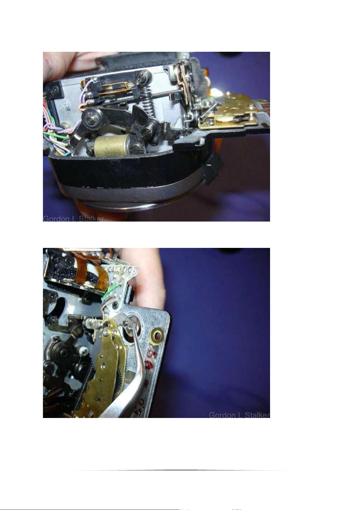
Disassembly
Before starting, make sure that you have provided yourself with a notebook and a pencil.
There are a number of variants of the internal wiring, and these may not correspond with
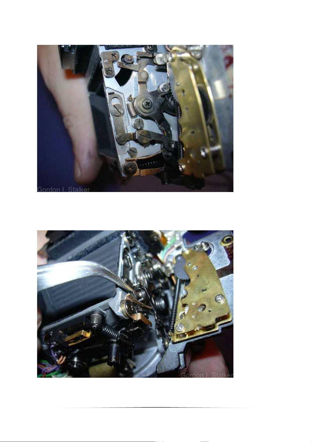
the camera shown here. Also, make sure that you have a tray for small parts, and be
prepared to spend several hours on the job.
If during the procedure after releasing a part it is stiff, or difficult to remove, stop and check
that all the screws, wires etc' have been removed. Never try forcing the part, you risk
permanent damage if you do.
If you start to get tired, stop and come back to the job. You will make mistakes that you will
regret later, and you are much more likely to lose your temper with stubborn fixings if you
allow yourself to get too tired. (I am speaking from experience here!)
Also, it is likely that your camera has not been disassembled for servicing since it first left the
factory. If this is indeed the case, all the internal light seals will probably require
replacement. As this disassembly will expose all of the seals these should be replaced at this
time. Deterioration of the seals will not only increase the risk of film fogging, but they
actually fall apart and crumble.
The resulting particles consists of a sticky black goo which gets into the viewfinder and
shutter, it is difficult to clean off and corrosive. If you have paint flaking off the film door
margins, the cause is the door seals dissolving the paint! If it gets onto the focusing screen,
the only way to get it off is to use an ultrasonic cleaning bath. Don't be tempted to try
solvents. That will completely ruin the screen! Small ultrasonic cleaners can be bought for
less than £100 these days, or you could take it to your local jewellers who will probably have
one andcould clean it for you.
Suitable seal kits can be had from a number of internet vendors, and are not expensive. Shop
around for the most comprehensive, almost all of the types and thickness of material will be
encountered in a single camera.
2
Page 3
Procedure.
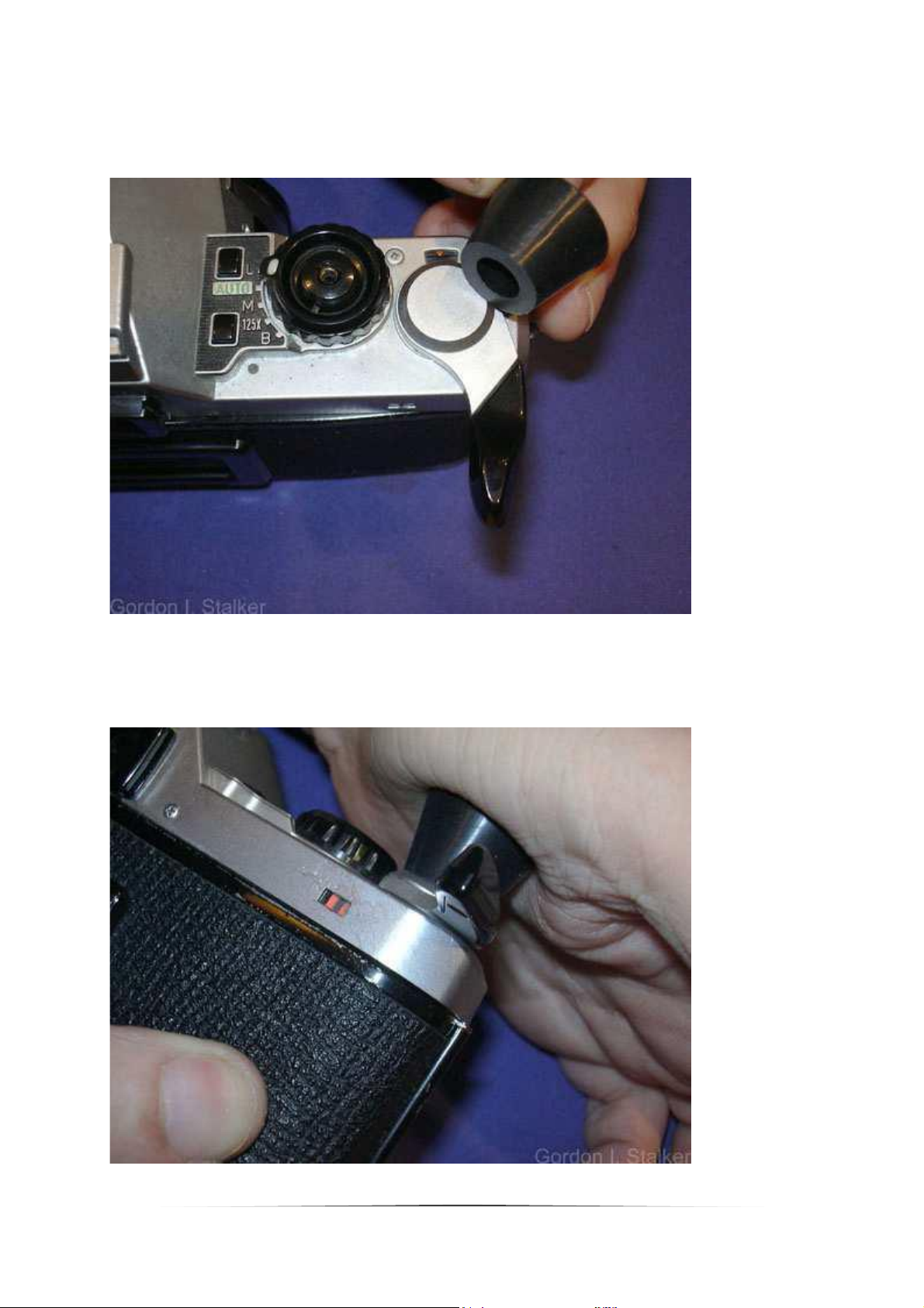
First remove the cap on the advance lever. This can be done with a rubber lens tool as
shown, or a rubber bung, turning the cap clockwise. It has a left handed thread.
Apply pressure firmly with the ball of the thumb. If this does not loosen the cap, use a small
piece of self amalgamating tape to increase friction. If that fails you should obtain (or make)
a 16mm flexiclamp. Alternatively, if you are prepared to spend three-quarters of an hour
cleaning it off with a wooden scraper, glue the bung onto the cap with superglue!
3
Page 4
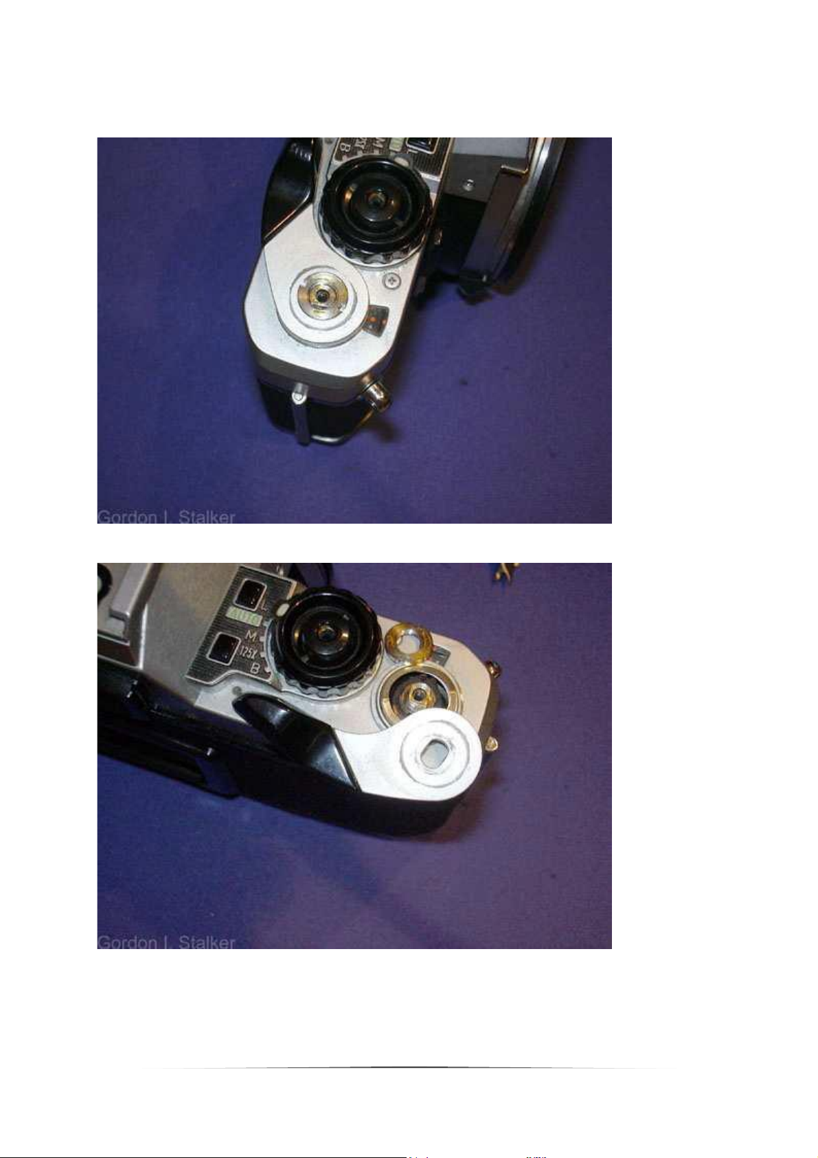
This exposes the retaining nut. This is also left-handed, and may be removed with an
improvised tool.
There is a large washer beneath the winder.
4
Page 5
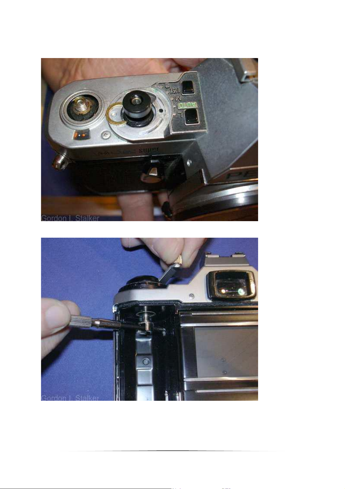
The release button should not normally need to be removed, but if you do need to remove it
then proceed as follows. If not skip to removing the rewinder. Using an improvised tool
unscrew the collar around the release button. (This is often quite loose!)
Remove the mode selector knob. Note the little pin beside the 'AUTO' setting. This needs to
be removed and kept safe.
5
Page 6
The mode selector has a long shaft which engages with a cam to select the mechanical
speeds.
The pin should be removed carefully, there is a tiny spring below it which could get lost.
6
Page 7
The pin often comes out with the spring stuck to it.
But it is not attached!
7
Page 8
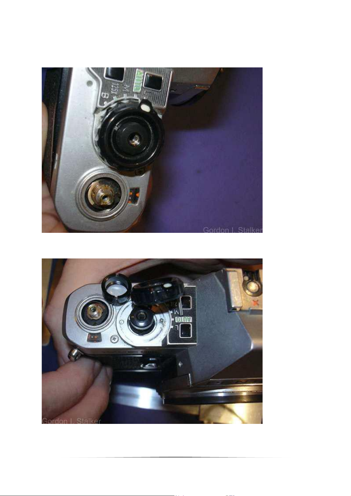
There is a 'C' washer fitted here. This controls the seating of the threaded collar, and may be
absent in some examples.
The rewind crank can be removed by locking the engaging dog, and turning the crank.
8
Page 9
Do not remove the rewind shaft unless you intend to remove the back at this point. Closing
the back without the rewind shaft makes it very difficult to release the latch. To make sure
you do not close the back inadvertently you can remove the back by sliding the screw shown
below down.
If you remove the back however, the shutter is exposed and may be vulnerable.
Removing the winder exposes the film speed selector retaining nut. This is conventionally
threaded.
9
Page 10

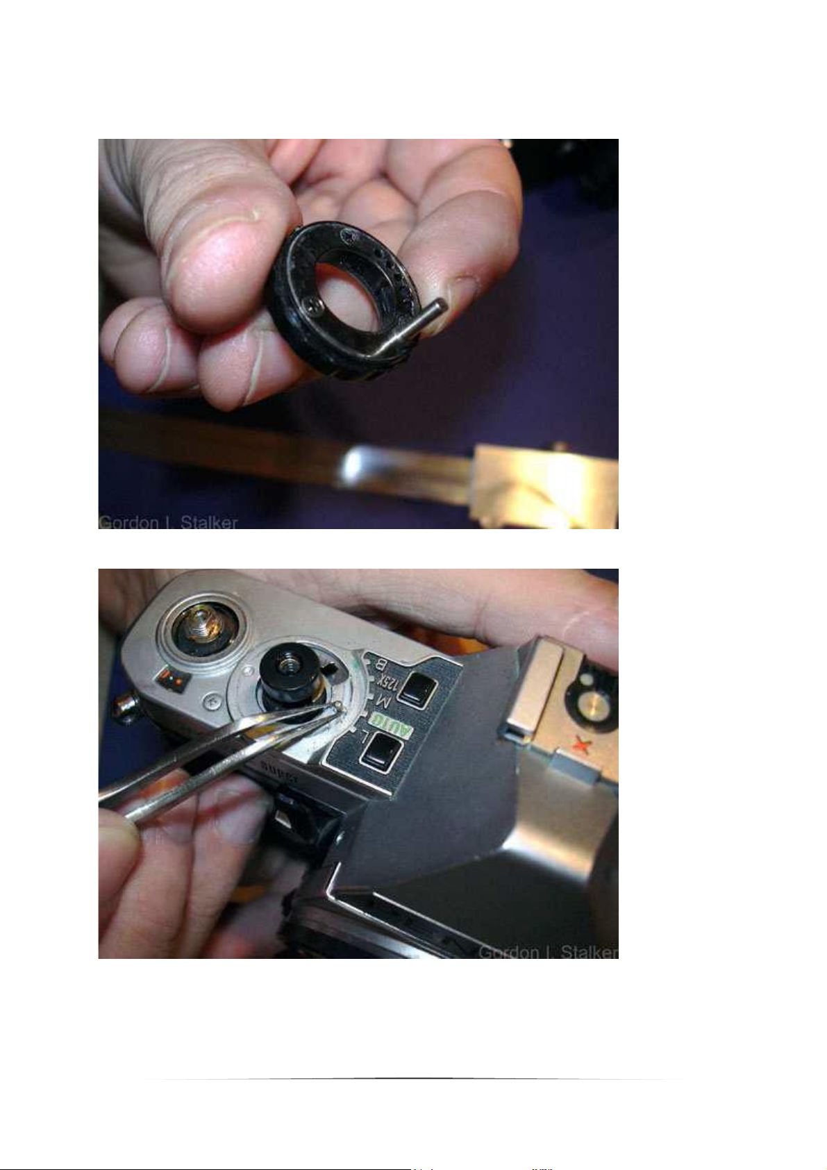
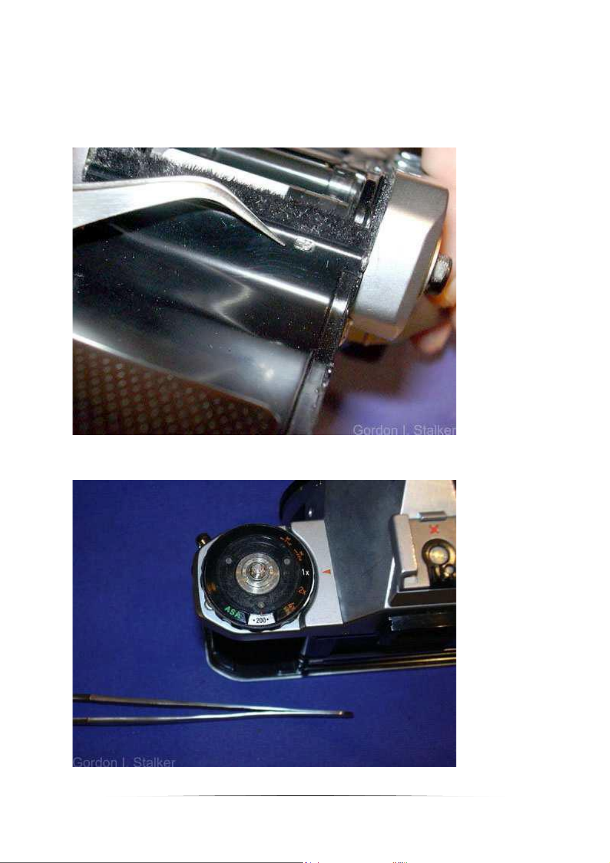
Before removing the selector dial, it is useful to set it to a default position as shown in this
example.
In this position the locating tab is in the position shown.
10
Page 11

Now remove the two screws on top of the cover. They are slightly different right and left.
The two screws here should be removed.
11
Page 12

There are two screws either side of the prism.
You can now ease the cover off. Note the chrome trim at the front of the prism.
12
Page 13

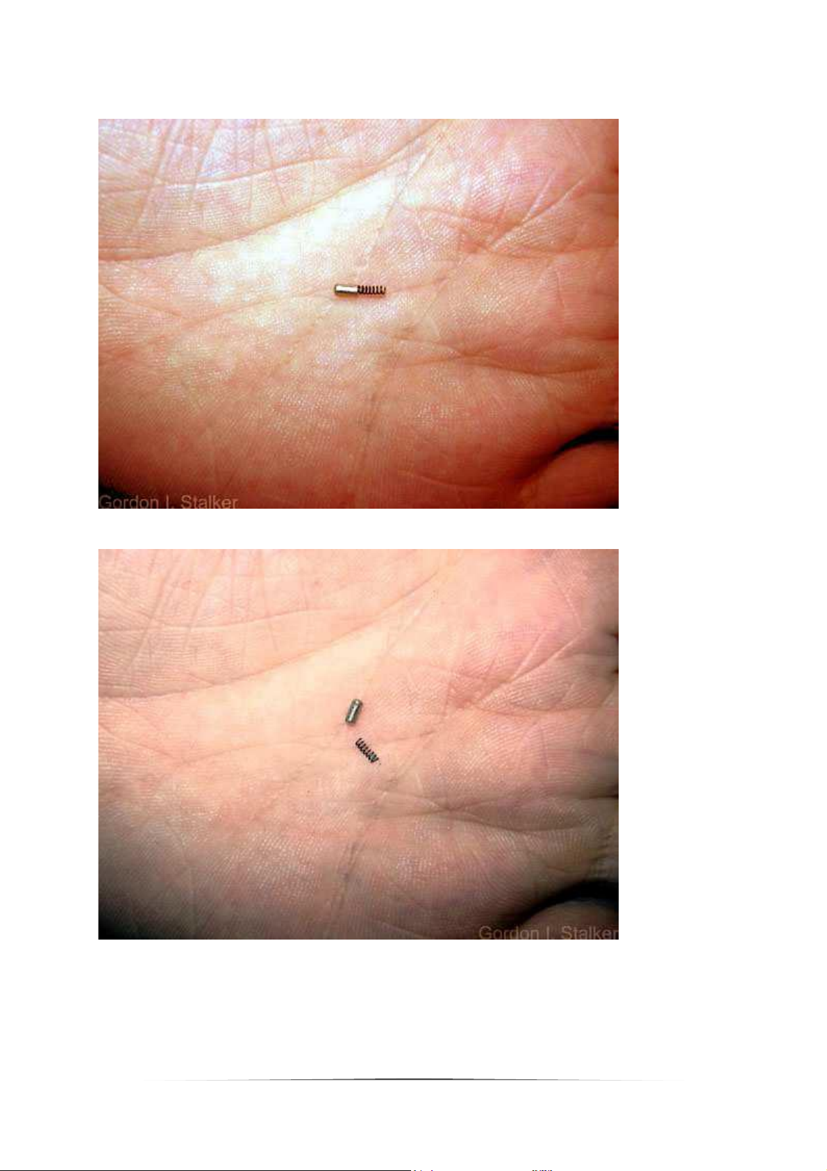
Detailed below is part of the film counter mechanism. You probably won't need to
disassemble this unless someone has forced a jammed camera, but the hair-spring indicated,
is easily dislodged from the groove ringed whilst working on the camera. Which is what has
happened here. It's a good idea to check this before replacing the top cover.
If you have removed the top to adjust shutter speeds or the LED display, the two presets
adjust each as labelled. Note that the PCB they sit on is a ceramic component. Cracks in this
part can be
responsible for
grossly
incorrect
shutter
speeds, and
this type of
board can be
very difficult
to repair. I
would
recommend
the use of
conductive
epoxy or paint
to repair faults
here.
13
Page 14
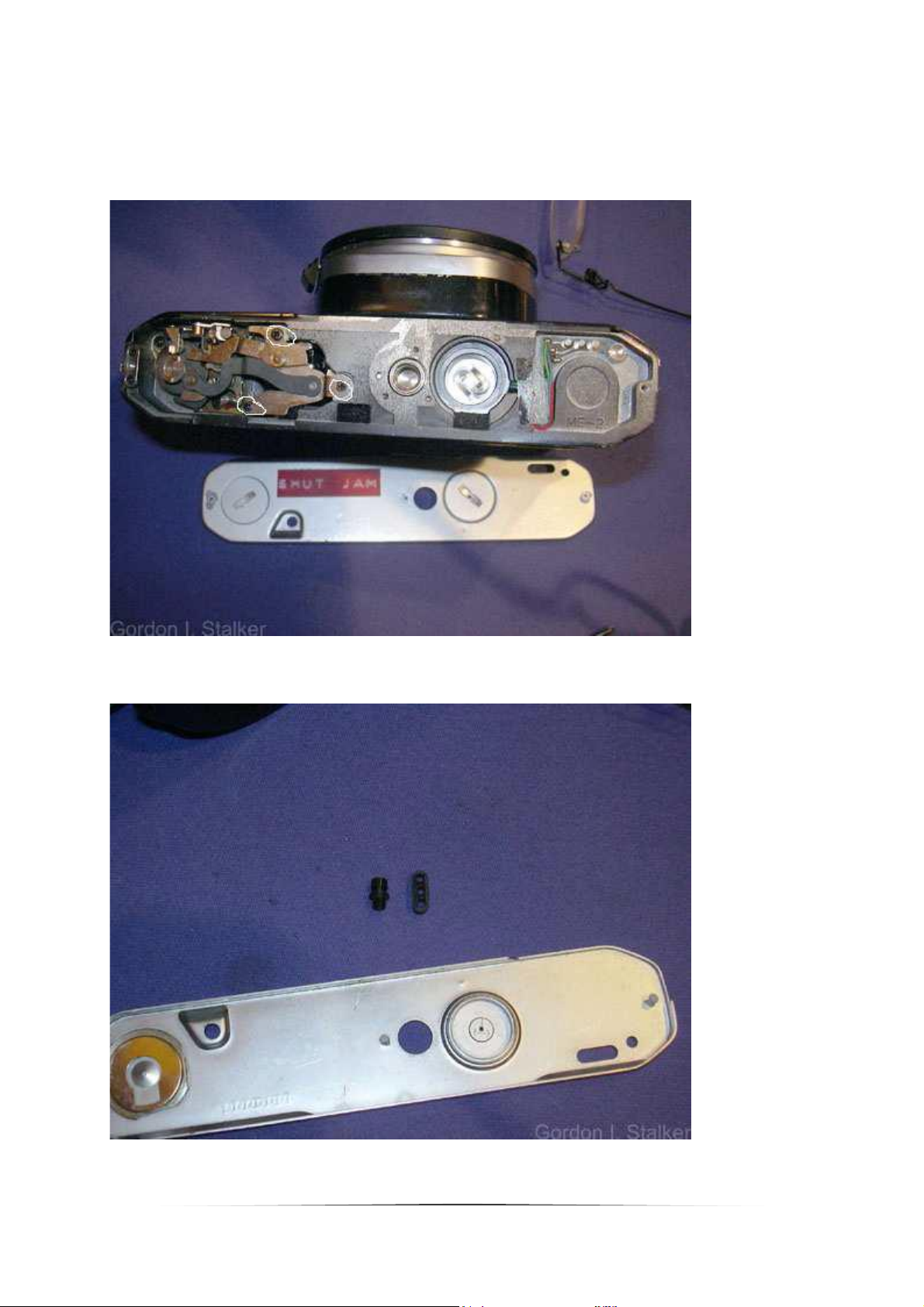
The bottom cover is retained by two screws. (The label indicated that the reason I'm taking
this one apart is to rectify a jammed shutter.) If the camera is locked (Jammed), you may
need to remove the three screws (highlighted.) securing the cocking arm guide before
removing the mirror cage. There is no need to do this just yet.
Two important plastic items released by removing the bottom cover. Make sure these are
kept safe.
14
Page 15

The leatherette trim should now be removed. To do this first remove the self timer lever.
The retaining screw is left handed, and can be removed with our improvised tool. There are
a number of washers underneath.
The Leatherette can be carefully peeled off. Start the edges with a dental probe. Note the
mechanism showing through the hole. This is the shutter release arm. It should not require
adjustment.
15
Page 16

To continue unsolder the white, brown, and pink wires on the board at the front. There is
also a metal strip soldered to the PCB which should be disconnected. Note, the order and
colours of these wires varies between examples. Note the correct locations on any particular
camera. The red, and blue wires should be unsoldered from the flexi-board, and the grey
from the flash-contacts.
16
Page 17

The view below shows the brass strip soldered to the PCB. (Between the brown, and the
white wires.)
The red wire here should be disconnected.
17
Page 18

The yellow wire on the left should be unsoldered.
Note the pillar at the front of the resistor plate.
18
Page 19

Now the speed selector resistor should be removed....
and the purple wire here unsoldered.
19
Page 20

These wires at the bottom also need to be unsoldered. Again the wire colours vary, so take
notes.
Now the lens standard and mirror cage can be removed. First make sure that the shutter is
cocked, by placing the advance lever temporarily on the advance shaft.
If the camera has locked this may not be possible, in which case removal will be easier if the
three screws securing the cocking arm guide shown earlier are removed. Don't attempt
removal of the guide, it is tricky, and unnecessarily. You only need to loosen the guide to
disengage the mirror, and shutter cocking levers.
Now remove the screws circled. Note the brass PCB brace on the left screw, this steadies the
electronics board which could work loose in its socket otherwise. There may also be two
washers between the body and the cage lugs, one brass the other copper, watch for these
and keep them safe.
20
Page 21

Then remove the screws circled below. There may be four washers glued to the body
beneath these screws. Take care not to dislodge them, or better still remove them, and label
each one so that each can be replaced exactly. These washers are important in ensuring that
the optical distance from the lens is the same for the film plane and focusing screen.
Remove the lens standard complete with mirror cage, prism, and electronics. Lift the
assembly about 5mm to disengage the cocking mechanism, and withdraw forwards.
21
Page 22

You now have access to the shutter mechanism.
To remove the shutter entirely, the two screws at the top should be removed, the battery
compartment, and the tripod mount should also be removed. The red wire is glued to the
body casting, and may be hidden beneath the light seal foam on this side of the casting. It
should peel away fairly easily, if not soften the glue with cellulose thinners. It is best if the
foam is removed at this point.
22
Page 23

There is also a single screw accessible from the rear securing the shutter.
At this point take some time to examine the workings.
The tweezers indicate the position of the shutter release latch, this is operated by the mirror
when it reaches the top of it's travel, releasing the opening curtain.
23
Page 24

This is the actual opening shutter latch, shown in the cocked position. This is operated by the
opening shutter cam.
This is the mode setting lever, the default position is 'B', centred is the x-sync mechanical
speed, and in the fully deployed position the speed is controlled electronically.
24
Page 25

Here the opening curtain is opened, and you can see the notch in the opening curtain latch.
I'm holding the mode selector in the 'B' position, as it is easily nudged to the x-sync setting
when handling. Depressing the camera release tab will shift the lever to this position without
releasing the shutter. (No mirror to couple the shutter!)
On release of the closing curtain, a striker on the closing shutter hits the mirror return catch,
causing the mirror to drop to it's resting position.
25
Page 26

More details on the shutter can be found in my page on the Pentax M series shutter. The
cocking mechanism can be lightly lubricated as shown. The lubricants here are not critical,
but it is as well to use oil recommended for cameras (or watches), as this will be formulated
to ensure long life and correct lubrication at a wide range of temperatures.
The circled area
shows the gap
which allows
access to the
scissor from the
bottom of the
camera.
This is the mirror cocking lever, shown in discharged position. The mirror is in it's resting
position.
The tightly coiled spring is the mirror return spring. It needs to be strong in order to reset the
mirror lifting spring beneath it.
You can also
see the 'magnet
switch'
assembly. This
primes the
shutter release
magnet in time
to hold back
the shutter
prior to
releasing the
closing shutter.
The large
cylinder at the
front acts as a
damper for
both springs,
which will have
an impact on
camera shake.
26
Page 27
Pushing this lever forward primes the mirror, and reveals the straight mirror lifting spring.
This is the body-mounted release lever operated by the shutter release button, and the
timer release escapement. It bears on the upper arm of the mirror release latch.
27
Page 28

The lower arm of the mirror release latch holds the mirror lifting arm in the mirror resting
position. The mirror return spring is under considerable tension at this point, which is a good
reason for making sure that the camera is not left in a primed state. Leaving a spring in a
stressed state for long periods can weaken it.
This is the mirror return catch. This is hit by the closing curtain striker to release the mirror
from the taking position. You can also see more of the lifting mechanism which bears on the
mirror release latch.
28
Page 29
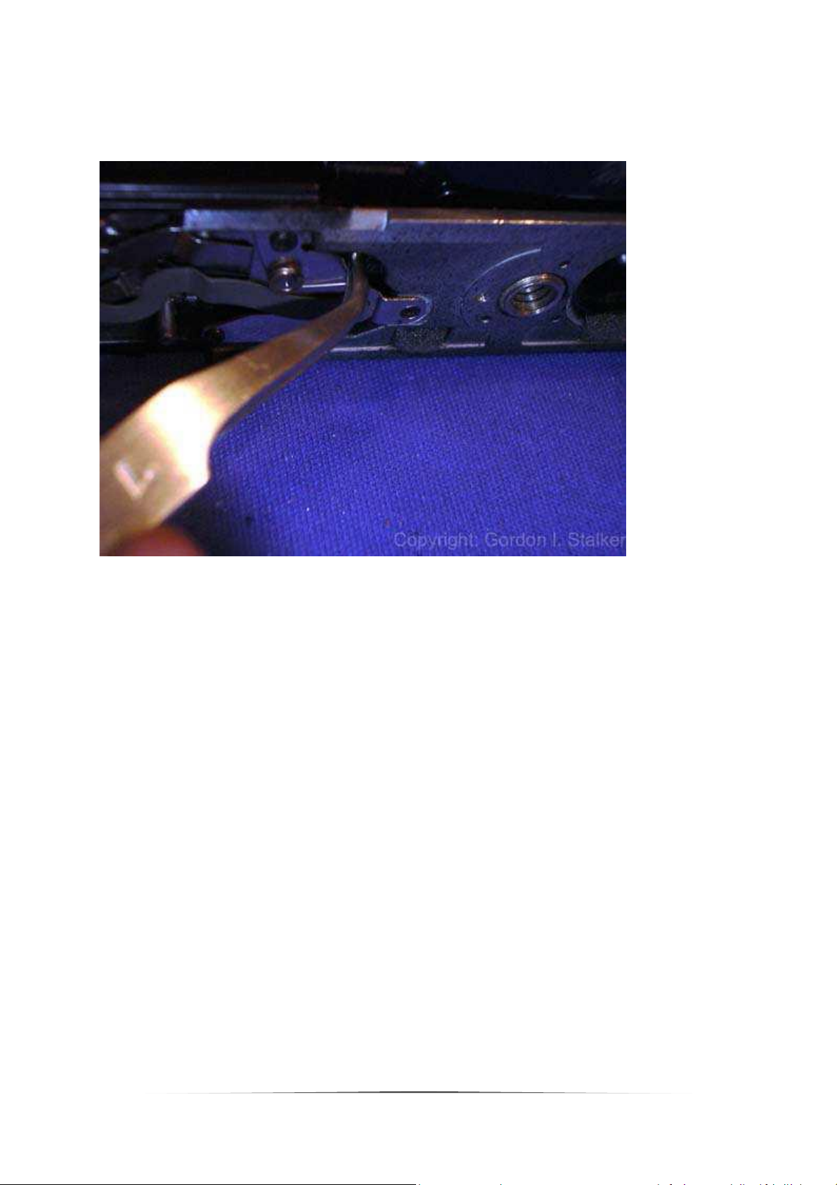
Note how the forked end locates into the spring release.
Indicated is the cause of most locked cameras and 'jammed shutter' faults. It is a rubber
buffer included to deaden the impact of the mirror return. In fact it can be removed
completely without harm, all it seems to be for is to reduce noise. Any additional jarring
caused at this point will not add to camera shake, the picture has already been taken.
29
Page 30

This lever is operated by the mirror lifting arm, and is responsible for releasing the opening
curtain just after the mirror comes to rest in it's upper position. There is a slight delay
between releasing the shutter latch and the curtain opening so that the mirror is sure to be
out of the way before it opens. This means that the latch actually operates just before the
mirror is fully up, the rest is down to the delay.
In the unlikely event that the shutter fires with the mirror in the way, then bending the
upper part of this arm downwards little will cure this. (If this seems a bit crude, I have to
point out that there are a number of official Pentax service manuals which recommend filing
parts to effect an adjustment!)
Note also that on this example (It's actually an MV in this picture) the 'rubber' buffer is now
a nylon part! It appears that this modification was applied to later models, as problems with
the soft rubber component emerged. However, unless you wait until the mechanism jams,
you can't tell which camera has the nylon part or the rubber part!
Reassembly
For the most part this is the reverse of disassembly, but the below points will came in
handy..
Replacing the mirror assembly.
First ensure the mirror, and shutter are cocked before assembly, then place the mirror
assembly onto the body resting on the front about 5-10mm above the bottom of the
camera.
Don't forget to replace any washers.
Then using a suitable probe inserted into the bottom of the cover, move the front 'scissor
blade' towards the front of the camera as shown below. While holding the scissor in this
position, slide the mirror assembly down into its proper position.
30
Page 31
Fit the nearest screw to the scissor first but don't tighten it. Then fit the two screws removed
from either side of the viewfinder, remembering the spacing washers beneath the mounting
lugs. Screw these home before inserting and screwing home the remaining three screws.
Before finally tightening the screws, check the operation of the shutter release.
Check the point at which the shutter releases with relation to the mirror by using a fingertip
on the edge of the mirror to stop it flipping when the release button is depressed, and gently
moving the mirror upwards with the fingertip until the shutter fires. This should happen
within 5mm of reaching the upper position. If it happens before then, remove the mirror
cage again, and bend the brass release arm as described above.
Replacing the leatherette
When replacing the leatherette, first clean the old glue off. A few drops of lighter fluid will
help here. Thinly smear contact adhesive on both the back of the leatherette and on the
front of the camera, and leave it to dry for about ten minutes. Carefully locate the
leatherette before pressing home.
Pay special attention to the area around the self timer arm, and make sure that the hole in
the leatherette does not foul the friction washer, and remove the glue around the timer
shaft before replacing the washer, otherwise you may end up gluing the washer to the front
of the camera which causes problems for the release timer.
Replacing the top cover
When replacing the top cover, place the mode selector switch in the 'AUTO' position before
placing. Once located, move the selector to the 'B' setting and back to 'AUTO' in order to
engage the control cams operated by the selector shaft.
The rest of the assembly is the reverse of the disassembly.
31
 Loading...