

Page 1

Page 2
ASAHI PENTAX KX
Product No.
KX
camera is fundamentally based upon SP type camera except
23700
Mirror housing and other exterior parts, therefore assembly and
disassembly procedures or some of the adjustments which are
included in SP type camera are not mentioned here.
In this manual, exclusive adjustments for KX are mentioned.
Items
A.
Preface
B.
f-stop indicator adjustment
C.
Blue needle adjustment
D. Main SW adjustment
E.
Light metering adjustment
F.
Galvanometer installation
KX~~)J~~~~$A~JIISP%FIJ~/~I-
BTLXTL>Q.
fia~a~1.i
BM,
&Cljtvflf;*?
%2$:h
C?-=ZL
b>TJ!!L-T&5ho
ID
L
:
?-A
,?
XI~V.
K
X$%~~,@I$$'#-,
S
P%"rl]h A 71-
6~1iZldLT2~1.
7
/b?iL
K
X$ifeC&j$F1:r,
TL
6.
A.
Preface
0
Lubricant
(G
21) is applied thinly on the mount surface of KX
and KM to prevent it from being scratched by a lens, when it
is mounted or dismounted.
Material of the mount for
KX
and
KM
is brass and that for
is stainless.
And mount ring of all interchangeable lenses are brass materials
except f 1.2/50mm lens of stainless mount.
Therefore, it
is
not allowed
to
wipe off the lubricant
(G
from the mount surface of camera.
0
Fleon
TF
(Dupont made or Mitsui chemical) is used for cleaning
exterior parts especially platstic materials.
If ether or alcohol is used on plastic materials, the plastic will
change
0
Do not push aperture-reader window from outside, because it
color.
falls into camera inside.
K2
21)
Page 3
B.
f-stop indicator adjustment
1.
Optics
B.
1.
ygl~
&,~;tfig
%y.%
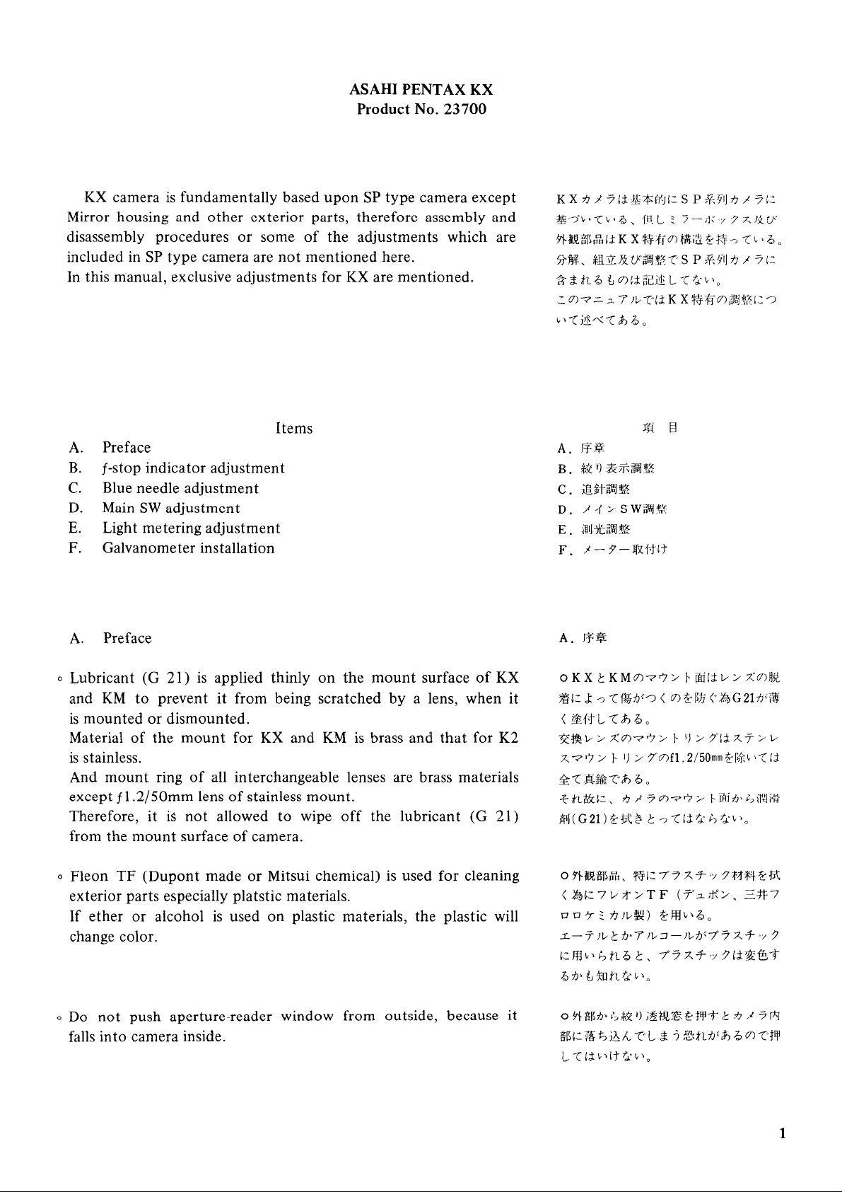
Optical ray reflects rather complicatedly as shown in Figure
therefore adjustment is very severe and critical.
k
Diaphragm
scale
ring
X
a:
b:
c:
X
X
X
=
63mm
=
62.5mrn-
=
64mm
1,
-t
-,
*#$lLFig.
1
mku
<
~:Fg#iz
$jw~i#-$~:.i%tll~:~h
XiM
Y
-8mm
Y
-8.5rnm
Y
-7mm
Fig.
I
i
Q
Ji~jjT
6
X3.
c:
X=
64mm
1.8185
(Not available lenses for f-stop indicator system)
6.71 135 - 600, 5.61400, 4.5/500, 8/ 1000
2.
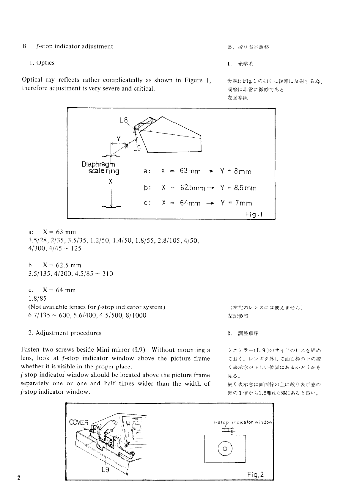
Adjustment procedures
Fasten two screws beside Mini mirror
(L9).
Without mounting a
lens, look at f-stop indicator window above the picture frame
whether it is visible in the proper place.
f-stop indicator window should be located above the picture frame
separately one or one and half times wider than the width of
f-stop indicator window.
t
f-s
top
ind~cator window
+
Fig.2
Page 4

Adjust mini-mirror
(L8)
position bending the cover of it with
finger or tweezers so that f-stop indicator window might come
in the correct position.
(Caution:
Every corners of picture frame must be visible during
this adjustment.)
After attaching the lens (standard lens etc.), each f-stop should
be clearly visible in the center part of f-stop indicator window.
If each f-stop is not visible clearly in the center portion, for
instance visible in upper or down part, adjust Mini mirror
(L9)
position loosening two screws evenly beside of it and pulling
it with tweezers so that f-stop might come just in the center.
And if f-stop deviates either left or right from the center portion,
loosen or fasten one of the two screws.
$29
&7k~h~~xLL~i2El:*Q@iz
:
3-(L
TFmLBCfT%Et
(
Z~~%H~B~C~@~~#C?Z?--
-zEk-c~.a#ETQIjfiim
v>z*
i&h*@') $;%%C~1&3
If2
;t
L&f ii&h'P~i\l~JL,t2~~~+, VlJ,tiB
km3t
7-(L
LTIB,BM>T Y7t.r
LT~
&f
3-(L
KB, @KBh.T8%$QQ
B)O,*.~--+)$-?Y>+.~
6.
(t$@v>x%)
r;
2Lro
&~Tm%l:JLkTQP~l&
9
)my4 pa2
+9i-j-T,
3
'1
t
&O,k+2+4i$
/.
TSIc,l.fB@i:
i~~~+~~.t:~a~c:nn+~.
i~h~&h~$ii:~3TL~~~I&:
9
)my4
pu)rxmi
f
=
/.
j-7524
r,
QL>)~
&f
Hri2C+h
:
=
f
=
5
C.
Blue needle adjustment
Trun two eccentric rivets @ and O to make them face the large
chamfering toward the direction of Galvanometer
a. Set shutter dial at "B", and turn the eccentric rivet
(J
100).
@
so that
blue needle might indicate "B" in the viewfinder.
b. Set shutter dial at'
"
1
OOO", and turn the eccentric rivet @ so
that blue needle might indicate " 1000" in the viewfinder.
C. ;g$t~~
2 $ni~,~\y
r
-
9-(
a.
>-r~ 5'-9"4711.%Bl:+.:,b
ziz
b.$fi3*7
@O,%.L\P"iK
b.
>-~~YP-P~~IL%'~ooo"~:~~I
1
LTWL+~~*~
++~~&@o,IG~L~~"~K%
snk3
5
100)n%)il:TiilIfTQ6~
7
4
+
~.3mmr[x
>9"-mT"B"gg$&
H.t.
7
4
>
~-~T"~OOO~
B$.
9
3%
LT
Page 5

c. Turn shutter dial from "1000" to
needle must indicate each shutter speed correctly.
If
it doesn't, readjust the eccentric rivets @ at
"1
000".
Eccentric rivet
For adjusting blue needle
indication at
@
;
"B"
critically.
"B"
or vise versa, blue
"B"
and O at
c
.
>T
,r
9-T4
"~"~ikinig1:.
h'&x~-
k~lf
5
L);L~~~?~~atj~c~i$j?z$
?lhbt)h~i;~79
{,~,L~T~K
ZIZ
~x$tm"B "~0)gir;${$!&j?+j-6~
FS~J;$XL
2
l;
2
L>,
1
7/~$"1000"LJ.i,"
B~L~:II+,
(
?j-'j-~~$f.
+ELTL>CI?
&
j
1
12
Eccentric rivet
For adjusting movable range of blue needle.
@
;
M:?:b
-
P
Fig,
D.
Main SW adjustment
When wind lever is set at closed position, there should be
0.3 - 0.5
SW lever
If there is no proper clearance, turn the eccentric rivet
obtainning proper clearance.
@
mm
clearance between eccentric rivet
.
@
and main
@
for
6
D.
%.r;SW$jg
-&LI?~/~-$~I#IAA%~~
,i.~s@)tr
+f-710.3-00:5 mmC:W%?$B.
;ELL~Z+T~~~&$~I:~~!G,L\~'~@
@Hk-bB,
$4
2
s
~f:&$1:
w
k~q-@mgdo
>
(~6
z
Page 6

When release lever
@
must ride on the eccentric rivet
0
is depressed half way, main
contact wires of main SW must be turned
E.
Light metering adjustment
SW
@
without fail, and two
"on".
lever
Testers:
Light value correction unit
f8
set ring.
Condition: ASA 100
F.
Galvanometer installallation
2.8V
(Light metering)
2.2V
(Batt. ch.)
T
adjuster (Power source)
F.
3-9-Rxi+
When galvanometer is installed, black
needle must be completely horizontal
at
30
with using Meter tester.
(MA-00-0
1
).
/--9-??Xxrl
i+if
as$tkn~.~
$tik"30"~&~
22
tiqq~t:
&%l:BE-4-ao
3
-
9
f
29-
-00-01)
Q
--RX.r+lf
(MA
I%H,
Page 7

ASAHI PENTAX
Product
ASAHI PENTAX KM is based upon ASAHI PENTAX SPF
(23
1
10).
Therefore, the different points from SPF are mentioned here in
itemized statement.
1.
BATTERY
SPF
KM
2.
KM is not equipped with stop-down metering device but
possible for stop-down metering.
3.
Galvanometer
Movable range of the needle for KM is wider than that for SPF.
Therefore galvanometer of
that of SPF.
1.345V
1.5V
(J
100)
(Mercury battery)
(Silver oxide battery)
KM
is not interchangcable with
No.
KM
23701
 Loading...