

Page 1
®
CM9760-MXB/
CM9760-MXBL
System 9760
®
Matrix Bay
Installation/
Operation Manual
C543M-A (7/03)
Pelco • 3500 Pelco Way • Clovis, CA 93612-5699 USA • www.pelco.com
In North America and Canada: Tel (800) 289-9100 or FAX (800) 289-9150
International Customers: Tel (1-559) 292-1981 or FAX (1-559) 348-1120
Page 2

CONTENTS
Section Page
1.0 GENERAL ......................................................................................................5
1.1 IMPORTANT SAFEGUARDS AND WARNINGS ................................... 5
1.2 CERTIFICATIONS ................................................................................. 5
1.3 UNPACKING INSTRUCTIONS .............................................................. 6
1.4 RECOMMENDED TOOLS .....................................................................6
2.0 GENERAL DESCRIPTION ............................................................................ 7
2.1 OVERVIEW ............................................................................................ 7
2.1.1 Models ........................................................................................ 7
2.1.2 Optional Equipment .................................................................... 7
2.2 PHYSICAL LAYOUT .............................................................................. 8
2.2.1 Matrix Bay Card Cage ................................................................ 8
2.2.2 Video Output Card ..................................................................... 16
2.2.3 Video Input Card ........................................................................20
2.2.4 Rear Panel Input/Output Cards ................................................. 24
2.2.5 Power Supply ............................................................................ 30
3.0 INSTALLATION ............................................................................................32
3.1 MOUNTING INSTRUCTIONS ............................................................. 32
3.2 CONNECTING POWER TO THE MATRIX BAY ..................................33
3.3 CONNECTING THE MATRIX BAY TO THE CONTROLLER ............... 34
3.4 LED DIAGNOSTICS ............................................................................ 35
3.4.1 Performing a Diagnostic LED Check ........................................ 35
3.5 CONNECTING VIDEO INPUTS/OUTPUTS ........................................ 35
4.0 FUNCTIONAL CIRCUIT DESCRIPTION ..................................................... 36
5.0 SYSTEM CONFIGURATION–FRAMING..................................................... 38
5.1 DOWNFRAMING .................................................................................39
5.2 SIDEFRAMING .................................................................................... 42
5.3 DOWNFRAMING/SIDEFRAMING ....................................................... 44
6.0 PROGRAMMING NOTES–ODDS AND ENDS ............................................ 47
7.0 SYSTEM TROUBLESHOOTING ................................................................. 53
8.0 SPECIFICATIONS ....................................................................................... 54
9.0 WARRANTY AND RETURN INFORMATION .............................................. 55
2 Pelco Manual C543M-A (7/03)
Page 3

LIST OF ILLUSTRATIONS
Figure Page
1 Front of Matrix Bay ............................................................................ 8
2 Matrix Bay Card Cage ....................................................................... 9
3 Matrix Bay Connection Geometry .....................................................10
4 Rear of Matrix Bay ............................................................................ 11
5 Power Supply Section of Rear Matrix Bay ........................................11
6 Alarm Connector ...............................................................................12
7 Matrix Bay and Rear Input Cards ..................................................... 13
8 Rear Input Card Mounting ................................................................ 14
9 Rear Input Power Supply Connector ................................................ 15
10 Video Output Card with 16 Monitor Outputs (CM9760-VMC16) .......16
11 Video Output Card Installation .......................................................... 17
12 Location of DIP Switches, Jumpers and Fuses ................................18
13 Video Input Card ...............................................................................20
14 Video Input Card Installation ............................................................. 22
15 Input Card LED and Fusing Locations ..............................................23
16 CM9760-RPC Rear Panel BNC Input Card ...................................... 24
17 Installation of RPC Input Card .......................................................... 25
18 DFC Card .......................................................................................... 27
19 RPL Card .......................................................................................... 28
20 CM9760-RPM Video Output Card .................................................... 29
21 Power Supply Installation ................................................................. 30
22 Jumper Position on Bottom of Power Supply ................................... 31
23 Mounting the Matrix Bay ................................................................... 32
24 Replacing Power Supply Fuses ........................................................33
25 Connecting the Matrix Bay to the CM9760-CC1 Controller .............. 34
26 Video Signal Flow–Block Diagram .................................................... 36
27 Video Signal Flow–Graphical Representation .................................. 37
28 System Configuration–Reference Conventions ................................38
29 Single Bay Configuration–256 Cameras x 16 Monitors .................... 39
30 Single Bay Downframe–256 Cameras x 32 Monitors ....................... 40
31 Downframe Configuration–256 Cameras x 128 Monitors .................41
32 Single Sideframing–496 Cameras x 16 Monitors ............................. 42
33 Sideframe Configuration–976 Cameras x 16 Monitors .....................43
34 Sideframe/Downframe Configuration–496 Cameras x
35 Sideframe/Downframe Configuration–976 Cameras x
36 Sideframe/Downframe Configuration–2048 Cameras x
37 Setup File Dialog Box with Comms Tab Opened ..............................48
38 Configuration File Dialog Box ........................................................... 48
39 Camera Files and Logical Numbers ................................................. 50
40 Physical and Logical Numbers Compared ........................................ 51
41 Physical/Logical Numbers, Sideframed Bays and Camera Files ...... 52
32 Monitors ....................................................................................... 44
128 Monitors ..................................................................................... 45
128 Monitors ..................................................................................... 46
LIST OF TABLES
Table Page
A Alarm Port Pin Definition................................................................... 12
B Output Card S2 Functions ................................................................ 19
C X55 Jumper Definitions .....................................................................19
DVideo Output Card LED Assignments ............................................... 20
E Physical Input Range per Slot Position............................................. 21
FVideo Input Card LED Assignments.................................................. 23
G Matrix Bay LED Assignments ........................................................... 35
Pelco Manual C543M-A (7/03) 3
Page 4

REVISION HISTORY
Manual # Date Comments
C543M 9/97 Original version.
2/98 Removed references that a second power supply is
6/98 Added Section 1.2, Certifications.
1/99 Revised Figures 4, 5, 6, 7, 8, and 24 per ECO #98-4147.
6/99 Running change. Revised Table B for NTSC and PAL
C543M-A 7/03 Revised manual for System 9760 support of 2048
recommended if the number of input cards exceeds 10.
Changed manual pagination.
models.
cameras and 512 monitors. Also updated graphics of
video input, video output, and DFC cards and revised
text as necessary. Included other miscellaneous
changes.
4 Pelco Manual C543M-A (7/03)
Page 5
Please thoroughly familiarize yourself with the
information in this manual
prior to installation and
operation.
1.0 GENERAL
1.1 IMPORTANT SAFEGUARDS AND WARNINGS
Prior to installation and use of this product, the following WARNINGS should be
observed.
1. Installation and servicing should be done only by qualified service personnel
and conform to all local codes.
2. Unless the unit meets NEMA Type 3, 3R, 3S, 4, 4X, 6 or 6P standards, it is
designed for indoor use only and it must not be installed where exposed to
rain and moisture.
3. Only use replacement parts recommended by Pelco.
4. After replacement/repair of this unit’s electrical components, conduct a resistance measurement between line and exposed parts to verify the exposed
parts have not been connected to line circuitry.
The product and/or manual may bear the following marks:
NOTE:
This device complies with
part 15 of the FCC Rules. Operation is subject to the following two
conditions: (1) this device may not
cause harmful interference, and (2)
this device must accept any interference received, including interference that may cause undesired
operation.
Radio and Television
Interference
This equipment has been tested
and found to comply with the limits
of a Class A digital device, pursuant to part 15 of the FCC rules.
These limits are designed to provide reasonable protection against
harmful interference when the
equipment is operated in a commercial environment. This equipment generates, uses, and can
radiate radio frequency energy
and, if not installed and used in
accordance with the instruction
manual, may cause harmful interference to radio communications.
Operation of this equipment in a
residential area is likely to cause
harmful interference in which case
the user will be required to correct
the interference at his own expense.
NOTE:
The CM9760-MXBL does
not require power; therefore, certification is not required.
This symbol indicates that dangerous voltage constituting a
risk of electric shock is present within this unit.
This symbol indicates that there are important operating and
maintenance instructions in the literature accompanying this
unit.
CAUTION:
RISK OF
ELECTRIC SHOCK.
DO NOT OPEN.
CAUTION:
TO REDUCE THE RISK OF ELECTRICAL SHOCK,
DO NOT REMOVE COVER. NO USER-
SERVICEABLE PARTS INSIDE. REFER SERVICING
TO QUALIFIED SERVICE PERSONNEL.
1.2 CERTIFICATIONS
The products identified below have been tested and certified for agency compliance as noted.
Agency Compliance Certification
Model CE FCC UL cUL
CM9760-MXB X X X
CM9760-MXB-X X
Applicable CE, FCC, UL, and cUL directives/standards:
• 93/68/EEC–CE Mark Directive
89/336/EEC, 92/31/EEC–Electromagnetic Compatibility (EMC) Directives
• FCC–47 CFR, Part 15, Subpart B, Class A
Pelco Manual C543M-A (7/03) 5
Page 6

1.3 UNPACKING INSTRUCTIONS
Unpack and inspect all parts carefully.
The matrix bay you receive should be populated with all the boards and associated
cables needed for your particular installation. In addition, jumper settings, board
installation locations specific to your order should already be completed.
Be sure to save the shipping box and any packing material, at least until it has been
determined that the equipment you have received is working properly. It is best to
keep the material anyway in case future problems warrant return of any equipment.
If an item has been damaged in shipment, replace it in its box and contact the
factory at 1-800-289-9100 or 1-559-292-1981. (International customers fax 1-559348-1120 for authorization and instructions.)
If an item needs to be returned to the factory for repair, consult the WARRANTY
AND RETURN section of this manual for instructions.
1.4 RECOMMENDED TOOLS
Pelco does not supply basic tools for the installation process. The following tools,
however, may be needed to install the product depending on your installation
geometry:
Crimp tools
Wire stripper
Straight and Phillips screwdrivers
Coaxial cable stripper
Wire cutter
BNC crimp tool
6 Pelco Manual C543M-A (7/03)
Page 7

2.1 OVERVIEW
The matrix bay is a peripheral product that is part of the System 9760® family. The
matrix bay provides all video input and output connections for the system. Each unit is
capable of accepting up to 256 camera inputs in 16 input increments and provides
up to 16 monitor outputs in 4 output increments. If more than 256 camera inputs are
needed, sideframing is required (see Section 5.2); if more than 16 monitor outputs
are needed, downframing is required (see Section 5.1). Version 8.03.006 and later
of CM9760-CC1 operational software enables sideframing and downframing to extend the number of inputs and outputs allowed to 2048 cameras and 128 monitors.
With the addition of CM9760-MDA (Master Distribution Amplifier) units, a maximum
of 2048 cameras and 512 monitors is supported. Note that the term
any device that can transmit a video signal and the term
device that can receive a video signal. VCRs and multiplexers are examples of
devices that can transmit or receive video signals.
All connections are made on the rear of the matrix bay and utilize standard BNC-type
connectors for video connections. All video inputs leave the factory terminated with
75 ohms (standard default). Non-termination (where applicable) is jumper selectable.
2.1.1 Models
2.0 GENERAL DESCRIPTION
camera
monitor
includes
includes any
CM9760-MXB Video matrix bay equipped with CM9760-MPS power supply.
CM9760-MXB-X Same as CM9760-MXB except 230 VAC, 50 Hz. (CE)
CM9760-MXBL Video matrix bay for video loop-out connections. Uses
120 VA, 60 Hz. (UL; cUL; FCC, Class A)
downframe looping cards (CM9760-DFL). No power required.
2.1.2 Optional Equipment
CM9760-MPS Matrix bay power supply (spare). Operates on 120 VAC, 60 Hz.
CM9760-MPS-X Matrix bay power supply (spare). Operates on 230 VAC, 50 Hz.
CM9760-VCC Video input (camera) card capable of accepting up to 16
CM9760-RPC Rear panel (BNC) card provides 16 BNC connectors used to
CM9760-DFC Downframe card and cable assembly used to connect multiple
CM9760-DFL Same as CM9760-DFC except has looping inputs.
CM9760-RPL Double wide rear panel card for single bay looping. Maximum
CM9760-VMC4 Video output (monitor) card providing 4 monitor outputs. Requires
CM9760-VMC8 Video output (monitor) card providing 8 monitor outputs. Requires
CM9760-VMC12 Video output (monitor) card providing 12 monitor outputs.
CM9760-VMC16 Video output (monitor) card provides 16 monitor outputs.
CM9760-VMM Video output module for expanding CM9760-VMC4, CM9760-
CM9760-RPM Rear Panel (BNC) Card provides 16 BNC connectors used to
camera inputs. Also requires a rear panel card (CM9760-RPC,
CM9760-RPL, CM9760-DFC, or CM9760-DFL).
connect camera inputs to matrix bay.
matrix bays together for output expansion purposes.
number of inputs per bay reduced to 128.
CM9760-RPM.
CM9760-RPM.
Requires CM9760-RPM.
Requires CM9760-RPM.
VMC8 or CM9760-VMC12 by one monitor output.
connect monitor to matrix bay.
Pelco Manual C543M-A (7/03) 7
Page 8
2.2 PHYSICAL LAYOUT
The matrix bay consists of the following items:
• Matrix Bay Card Cage
•Video Output Card (the 17
12 or 16 outputs and front loading)
•Video Input Cards (up to 16 total; all identical and front loading)
• Rear Panel Input Cards (there are, at present, four types of Rear Panel Input
cards that can plug into any one of 16 rear loading Video Input Card positions)
• Rear Panel Output Card (at present, there exists only one type of Rear Panel
Output card)
• Power Supply (shipped as 120 or 230 VAC).
The following paragraphs illustrate and describe the function of each of the bulleted
items just mentioned.
2.2.1 Matrix Bay Card Cage
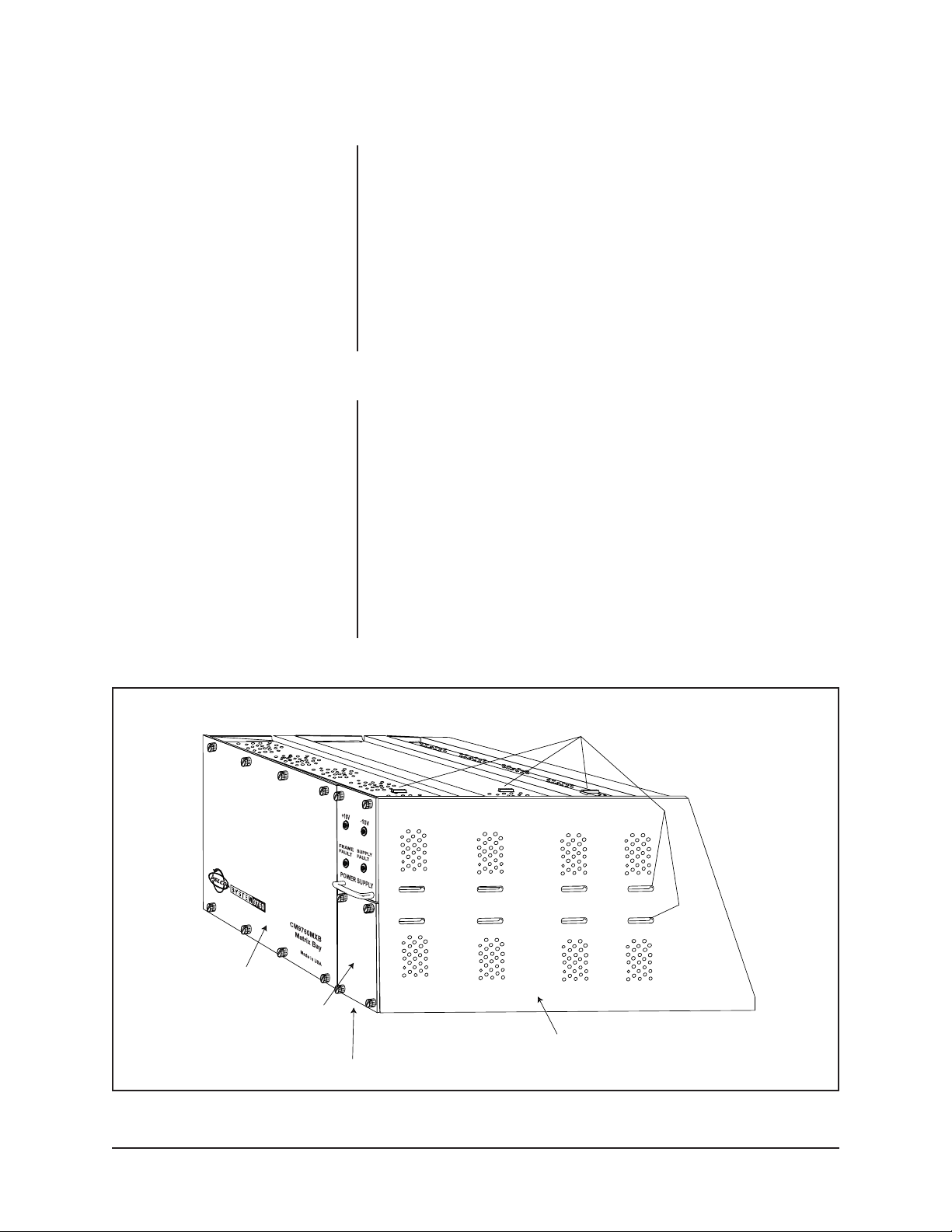
The matrix bay is pictured in Figure 1. The right side panel (power supply side), and
the top and bottom panels of all units are perforated with circular cut-outs to facilitate air circulation. Even though the matrix bay is a low power device and contains
no separate circulation fans, it is a good idea, if possible, to leave 1 RU (1.75")
between it and other installed bays. A fully loaded matrix bay, like all electrical
devices, does generate some heat.
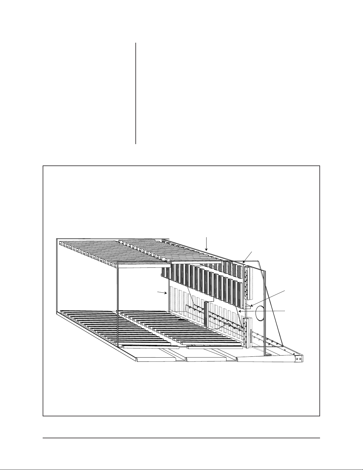
The Cage of the matrix bay provides the skeleton into which all the bulleted items
listed in Section 2.2 fit. Figure 1 illustrates a matrix bay populated with one power
supply (the panel with the handle on it); the covered opening immediately below that
has a blank-off plate installed where a second power supply is installed if needed.
The card cage cutouts indicated in Figure 1 accept the tabbed appendages of the
panels that form the interior walls of the top and bottom power supply bays and
anchor them in place. If the installed power supply, the blank-off panel, the right side
panel and the large front-cover panel are removed from the unit in Figure 1, one can
see the layout of just the cage itself as show in Figure 2.
th
card, consists of one card type; available in 4, 8,
FRONT COVER
PANEL
BLANK OFF
PLATE
POWER
SUPPLY
RIGHT SIDE
PANEL
Figure 1. Front of Matrix Bay
TAB INSERTS PROVIDE
SUPPORT FOR SIDE, FLOOR
AND CEILING OF POWER SUPPLY BAYS
8 Pelco Manual C543M-A (7/03)
Page 9
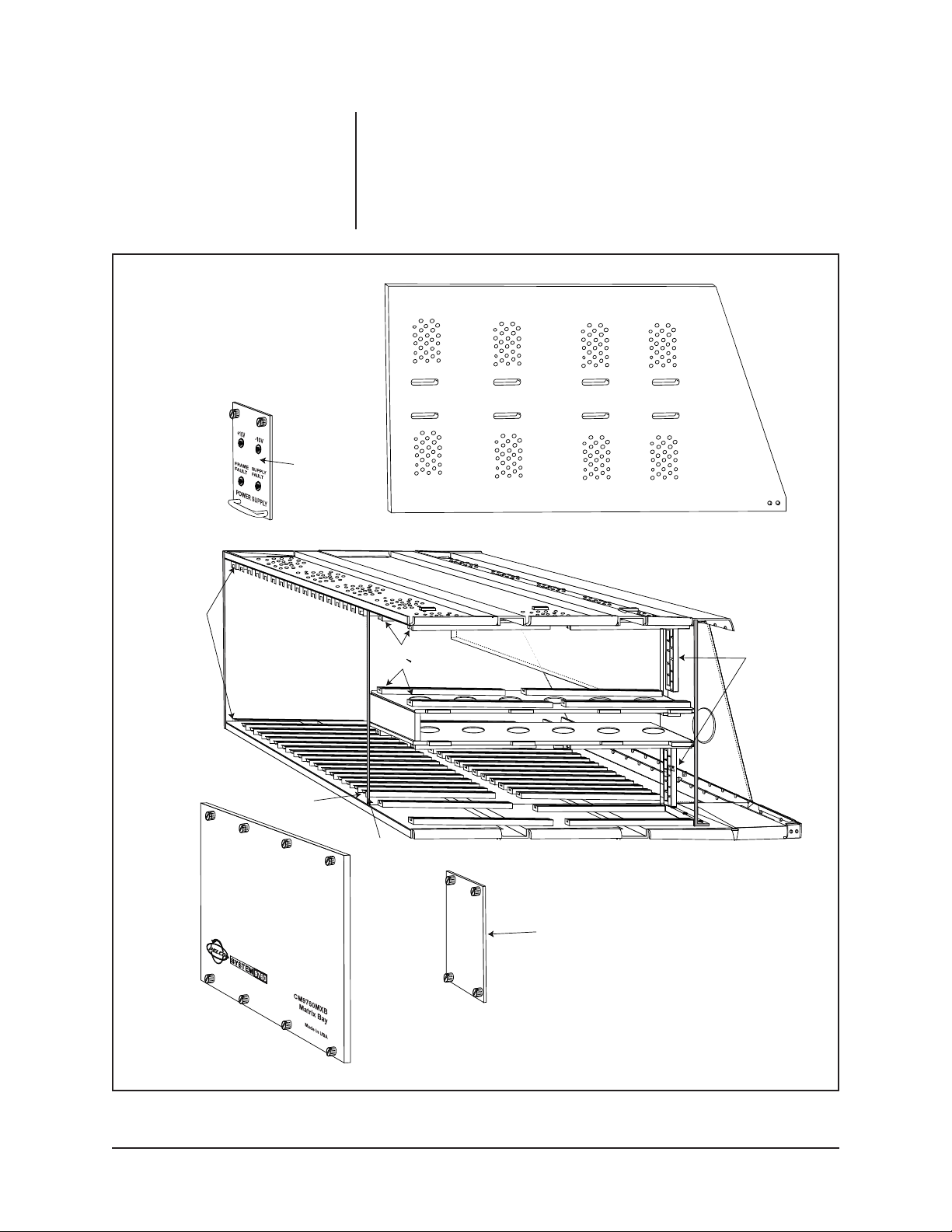
POWER SUPPLY
COVER
As already mentioned, room is made on the right side of the unit for the installation
of up to two power supplies. Two guide rails situated at the top and bottom of each
power supply bay exist to accept the power supply units. Seventeen sets of guide
rails (top & bottom) located to the left of the power supply provide for the installation
of up to sixteen Video Input Cards and one Video Output Card. The empty positions
are labeled left to right, 1 through 16. The seventeenth position (next to the power
supply bays) is the Video Output Card position. The Video Output card is slot specific and must always be installed in this slot position.
GUIDE RAILS
VIDEO OUTPUT
CARD POSITION
POWER SUPPLY
GUIDE RAILS
LEFT WALL
OF POWER SUPPLY
HOUSING
BLANK OFF
PLATE
POWER
SUPPLY
CONNECTORS
Figure 2. Matrix Bay Card Cage
Pelco Manual C543M-A (7/03) 9
Page 10
NOTE:
There are three (3) connectors into which any Video Input or
Output Card plugs into: the two on
the backplane and one on the appropriate rear panel card (see Figure 3).
This connection geometry holds true
for all installed front loaded Video Input and Video Output cards.
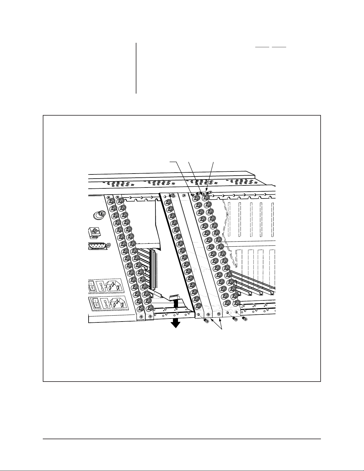
Further disassembly allows one to see the backplane upon which are located two
of the three connectors into which all installed Video Input and Video Output cards
plug into (refer to Figure 3). The back plane is held in place by rectangular bar stock
(top and bottom) which runs the width of the bay between the left side panel and
the power supply plate which secures it in place. Power supply units, Video Input
and Video Output Cards are all installed from the front of the unit. All other cards
are installed from the rear of the unit (refer to Figure 4).
Also note in Figure 3 the baffle plate installed for CE purposes with appropriate
openings for Rear Panel cards and their connectors to fit through. The baffle plate
itself, extends the width and height of the matrix bay itself (excluding power supply
sections).
The three connectors (consisting of two on the backplane and a single connector
provided by a Rear Panel card as indicated in Figure 3) constitute the connection
geometry for all Video Input and Output Cards. For any given card position an
associated Rear Panel card (card type dependent on the function of the matrix bay
into which it fits) must be installed FIRST.
REPRESENTS CE
BAFFLE PLATE
NOTE EXAMPLE OF VERTICAL ALIGNMENT
ORIENTATION INTO WHICH ALL VIDEO/OUTPUT
CARDS PLUG INTO (OUTPUT CARD SPECIFIC
TO SLOT 17)
BACKPLANE
BAR STOCK
REAR PANEL
CARD
Figure 3. Matrix Bay Connection Geometry
10 Pelco Manual C543M-A (7/03)
Page 11
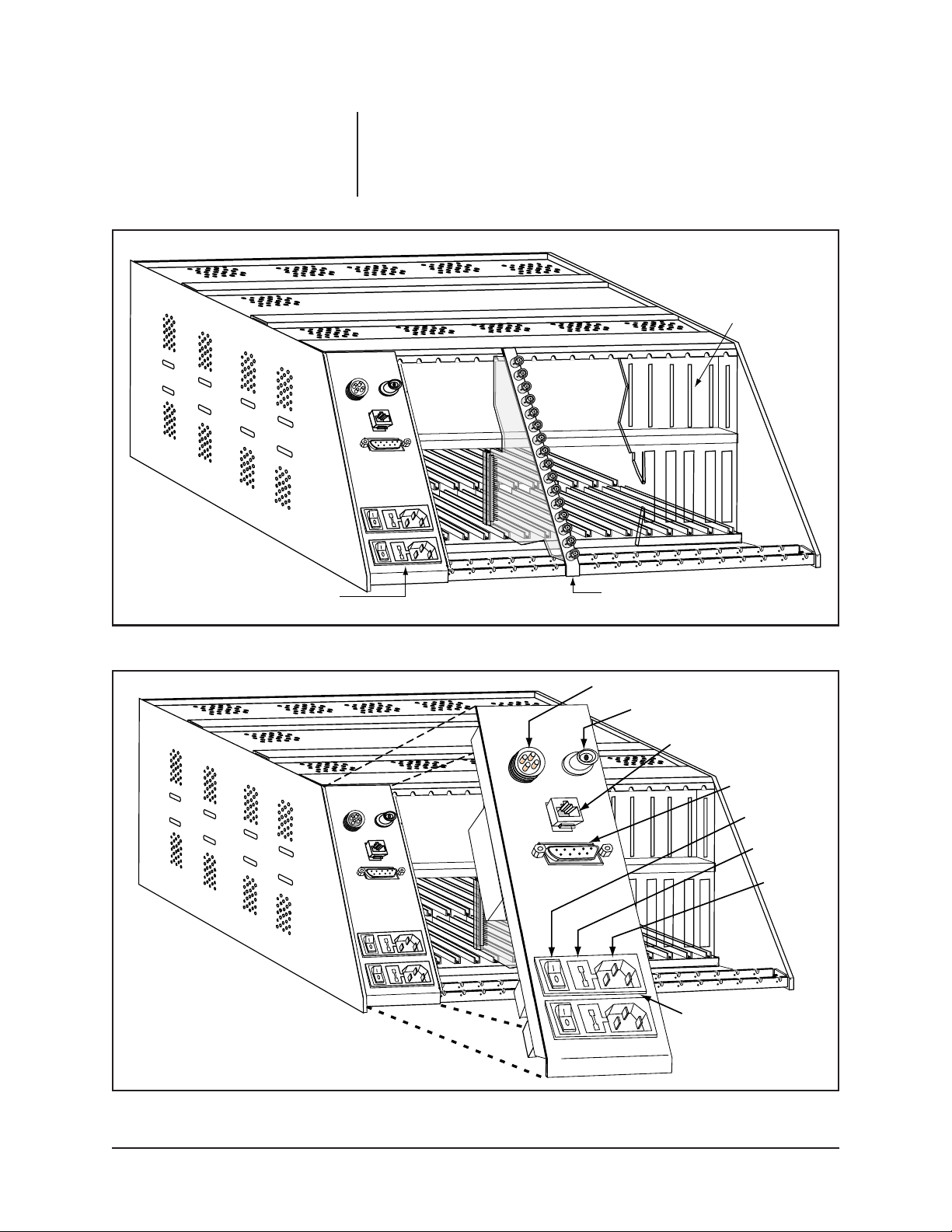
A rear view of an empty matrix bay is shown in Figure 4.
The plate covering the rear section of the matrix bay dedicated to the power supply
bays is shown on the left in Figure 4. This panel is populated with several items of
importance, refered to in Figure 5. Located at the top left corner of the panel is the
Alarm Port connector.
CE BAFFLE
PLATE (PARTIAL)
POWER SUPPLY COVER
Figure 4. Rear of Matrix Bay
REAR PANEL CARD
ALARM PORT
VIDEO BLACK LEVEL
OUTPUT BNC
RJ-45 DATA PORT
DB9 PORT
POWER
SWITCH
FUSE
HOLDER
VOLTAGE
IN
INPUTS AND CONTROLS
FOR TOP POWER SUPPLY
Figure 5. Power Supply Section of Rear Matrix Bay
Pelco Manual C543M-A (7/03) 11
Page 12
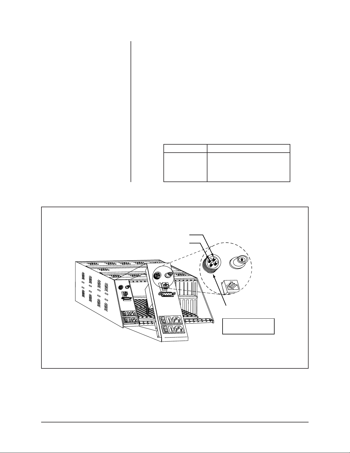
A single Alarm port is provided with each matrix bay which facilitates a relay output
(contact closure) to operate remote alarm circuitry in the event of a system malfunction. The relay operates in conjunction with the front panel fault LEDs (discussed
later in Section 3.4) to notify personnel when a hardware problem occurs. The
Alarm Relay contact closure will activate (close) if there is:
1. A power supply failure.
2. A frame fault including fuse failure on the Input card.
3. An Output card failure.
4. A communication fault with an Input or Output card.
If wiring to this port, use the 4-pin audio connector supplied with the unit (refer to
Figure 6 and Table A).
Table A. Alarm Port Pin Definition
Pin Description
1 Relay One Common
2 Relay One Normally Open
3 Not Used
4 Not Used
NORMALLY OPEN
COMMON
Figure 6. Alarm Connector
ALARM PORT
4-PIN DIN SOCKET
ON THE REAR LEFT PANEL
OF THE VMB
12 Pelco Manual C543M-A (7/03)
Page 13
To the right of the Alarm Connector is a Video Black Level Output BNC which can
be used as a reference sync output to allow for genlocking of peripheral devices.
The signal level for this output is 300 mV. The connection for this output is a standard BNC connector. The output has a 75-ohm termination. The Video Black Level
BNC can be seen in Figure 5.
Below the two connectors just discussed is the RJ-45 connector or data port, which
provides the main RS-422 communication path between the matrix bay and an
appropriate SerCom port on the rear of a CM9760-CC1.
Power supply input terminal plugs, ON/OFF switches, and power supply input fuses
for both power supply positions (whether the power supply is installed or not) are
located at the bottom of the power supply panel. The top set of this twin configuration is for the top power supply; the bottom for the bottom (refer to Figure 5). Further
details of power supply configuration are discussed in Section 2.2.5 and 3.2.
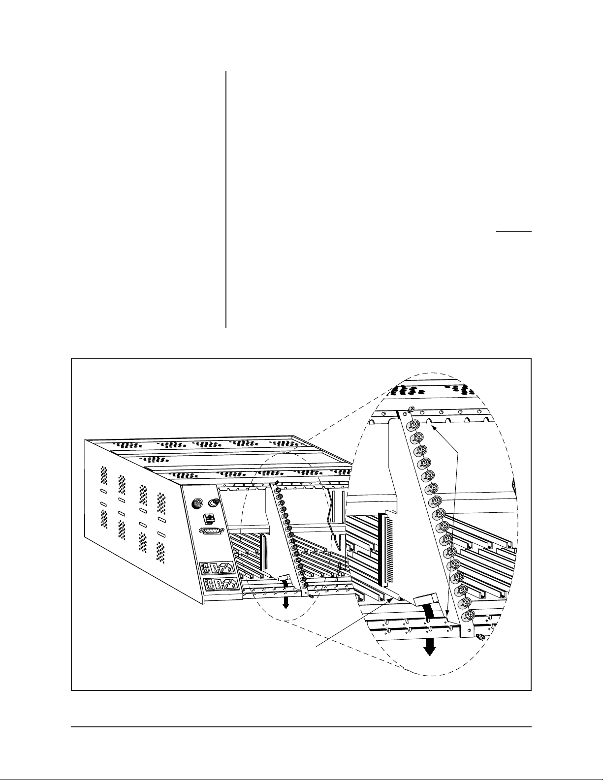
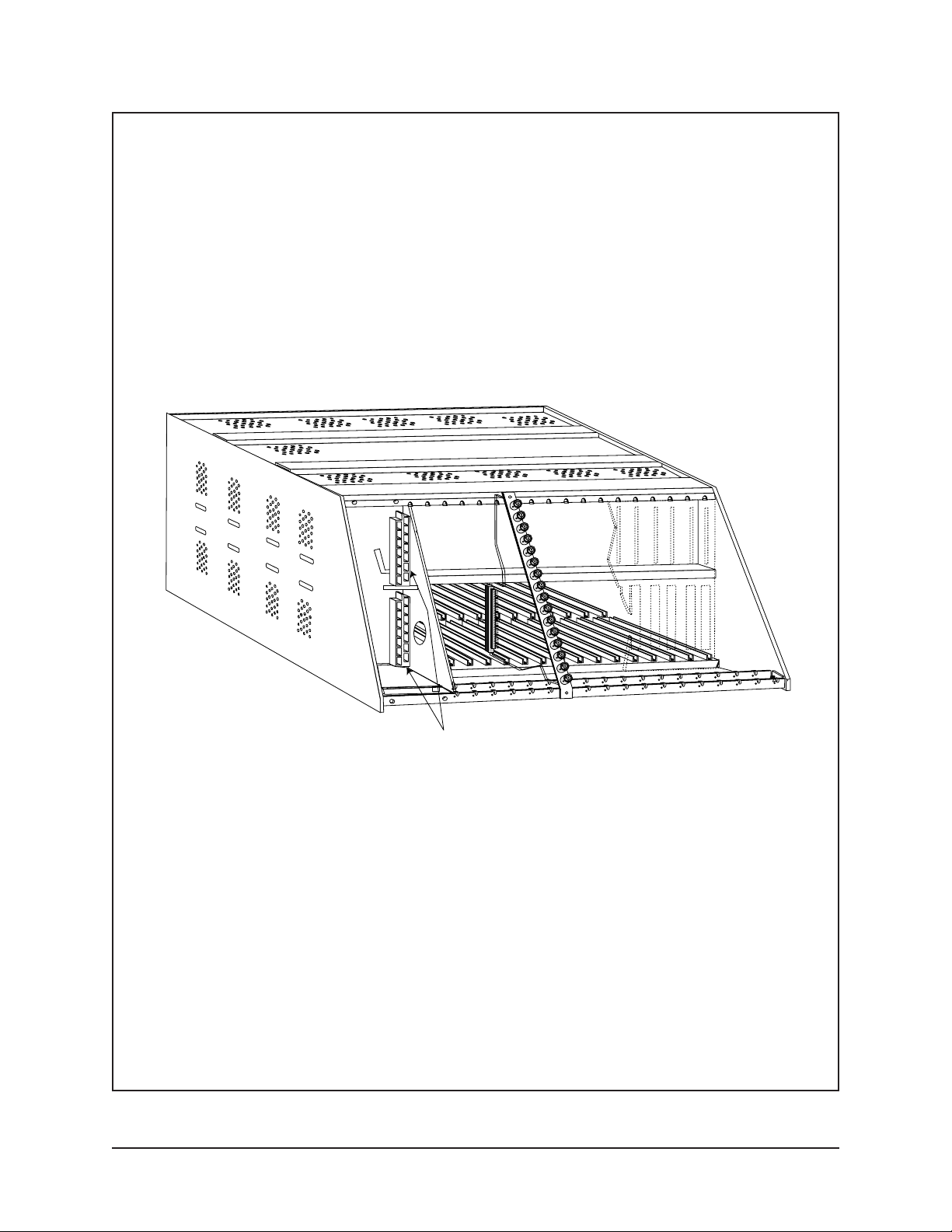
To the right of the power supply bays are the openings for installing the
rear panel
Input and Output cards. These cards provide a video signal path for the Video Input
and Output cards that plug into the matrix bay from the front. These unique, triangular shaped cards are held laterally in place by top and bottom notched rails and
a small rear portion of the guide rail into which the cards fit (refer to Figure 7).
In addition, the cards are snugly secured to the matrix bay frame by screws which
hold the top and bottom of each card’s faceplate to the frame of the matrix bay
(refer to Figure 8). The dual BNC Rear Input card discussed in Section 2.2.4 is held
in place with four screws, two at top and two at bottom. Unused rear openings are
covered by appropriately sized blank plates.
NOTCHED
RAILS
INTO
WHICH
CARDS
FIT
REAR INPUT CARDS
SLIDE PARTIALLY INTO
BACK PORTION OF
CARD GUIDE
DOWNFRAMING
PATH
Figure 7. Matrix Bay and Rear Input Cards
Pelco Manual C543M-A (7/03) 13
Page 14
These rear input cards should always be installed
FIRST
, before the correspond-
ing Video Input and/or Output cards in the front of the unit are installed.
If we remove the left rear power supply panel with its associated connectors, you
can better visualize the backside of the power supply connectors into which the
individual power supplies inserted from the front of the matrix bay are located.
External power connected to the rear power supply input panels is routed and
attached to these connectors to provide input power for the power supply itself
(refer to Figure 9).
VIDEO OUT
(LOOPING)
VIDEO IN CM9760-RPL
DOWN FRAME
PATH
BLANK
PLATES
Figure 8. Rear Input Card Mounting
14 Pelco Manual C543M-A (7/03)
Page 15
REAR VIEW
OF POWER
SUPPLY CONNECTORS
Figure 9. Rear Input Power Supply Connector
Pelco Manual C543M-A (7/03) 15
Page 16
2.2.2 Video Output Card
Pelco Part Number Designation (CM9760-VMC)
What Does It Look Like?
The Video Output Card can contain up to 16 monitor outputs with titling. The card
may be purchased with 4, 8, 12, or 16 monitor outputs:
• CM9760-VMC4—provides 4 monitor outputs.
• CM9760-VMC8—provides 8 monitor outputs.
• CM9760-VMC12—provides 12 monitor outputs.
• CM9760-VMC16—provides 16 monitor outputs.
Figure 10 illustrates the CM9760-VMC16 Video Output Card.
MONITOR
OUTPUTS
WITH TITLING
Figure 10. Video Output Card with 16 Monitor Outputs (CM9760-VMC16)
Note that a CM9760-VMM video output module can expand the number of monitor
outputs on a CM9760-VMC4, CM9760-VMC8, and CM9760-VMC12 Video Output
Card. Each CM9760-VMM video output module provides one monitor output.
16 Pelco Manual C543M-A (7/03)
Page 17
CARD HANDLES
SLOT SPECIFIC
TH
SLOT
17
Where Is It Installed?
The Video Output Card is located behind the front cover of the matrix bay. It is the
only card that is slot specific in the matrix bay (slot 17, to be specific). Refer to Figure
11. To install, simply line up the edges of the card with the top and bottom card
guides, slide the card in toward the rear of the unit until it is seated firmly with the
connectors on the back plane as well as with any associated rear panel card connector. To remove, grab the handles on the front card edge and firmly pull straight out.
Figure 11. Video Output Card Installation
What Are Its Functions?
The Video Output Card handles several functions; the most important of which are:
1. Routes regular video from the internal input bus, adds idents (if applicable)
and routes the signal through the system to the output monitors.
2. In the case of video loss, the output card will maintain video reference levels
and route black video for ident purposes.
3. Video loss compensation throughout the system via the video output amplifier.
Pelco Manual C543M-A (7/03) 17
Page 18

Other Important Items
DIP Switch and Jumper Settings
The matrix bay has a DIP switch (S2) and jumpers (JP2 and X55) located on the
Video Output Card that enable the selection of different options. These are normally
set in the proper position upon leaving the factory. However, it is recommended that
the settings be checked prior to operating the system (the other “front loading”
Video Input Cards have no DIP switches or jumpers to verify). Refer to the following
paragraphs for a complete description of the switches and jumpers on the Video
Output Card.
Refer to Figure 12. Switch S2 determines the communications baud rate, how the
system will operate on power up and whether video loss detection is enabled or
disabled. Refer to Table B for S2 switch assignments.
RED DS6
GREEN DS5
GREEN DS4
DS3
AMBER DS2
DS1
RESET
SWITCH
1
23
4
ON
S2
(SEE TABLE B)
FUSES, BOTH .7ASB
F6
F7
JP2
X55
(SEE TABLE C)
Figure 12. Location of DIP Switches, Jumpers and Fuses
18 Pelco Manual C543M-A (7/03)
Page 19

DIP switch 2 has the following functions:
S2
1 234
Table B. Output Card S2 Functions
S02
Description 1234
2400 Baud OFF OFF
4800 Baud OFF ON
9600 Baud ON OFF
19.2 K Baud ON ON
NTSC* OFF
PAL* ON
Default setting OFF
Must be ON for VIDEO LOSS
feature to operate ON
*X55 jumpers (refer to Table C) need to be set per Table C.
Setting the Jumpers on the Video Output Card
There are two jumper locations on the Video Output Card (refer to Figure 12 inset).
JP2 and X55. JP2 is used to control the program loading sequence and must always
have a jumper installed for proper operation. X55 is an eight-position header used
to set the standard required for video black generator operation. Refer to Table C
for a complete list of the available standards and the jumper location.
JP2 is a two-pin header used to control the program loading sequence and
must always have a jumper installed for proper operation.
X55 is an eight-pin header used to set the video standard for the video black
generator.
Table C. X55 Jumper Definitions
STANDARD OSC. FREQ. 1-2 3-4 5-6 7-8
SECAM1 5.0 MHz ON ON ON ON
SECAM2 5.0 MHz ON ON OFF ON
624 5.0 MHz ON OFF ON ON
PAL/CCIR 5.0 Mhz ON OFF OFF ON
NTSC1 5.034964 MHz ON ON ON OFF
NTSC2 5.034964 MHz ON ON OFF OFF
524 5.034964 MHz ON OFF ON OFF
PAL-M 5.034964 MHz ON OFF OFF OFF
Pelco Manual C543M-A (7/03) 19
Page 20

Video Output Card LEDs
The Video Output Card is equipped with six LEDs labeled DS1, DS2, DS3, DS4,
DS5, and DS6. Refer to Table D for a complete description of the Video Output
Card LEDs. Refer to Section 3.4.1 for further information regarding LED diagnostic
checks.
Table D. Video Output Card LED Assignments
LED COLOR WHEN LED IS ON
DS1 to DS3 Amber Always ON, No assignment
DS4 Green -10 VDC is OK
DS5 Green +10 VDC is OK
DS6 RED Communications failure with the CM9760-CC1
2.2.3 Video Input Card
Pelco Part Number Designation (CM9760-VCC)
What Does It Look Like?
The Video Input Card is illustrated in Figure 13
There can be from 1 to 16 Video Input Cards installed in a matrix bay. Your particular matrix bay has been shipped from the factory with the specified cards installed.
Figure 13. Video Input Card
20 Pelco Manual C543M-A (7/03)
Page 21

Where Is It Installed?
The Video Input Card is located behind the front panel of the matrix bay and is
found in any one or all of the available 16 slots provided there. Video Input cards
are not slot specific (any card can go into any slot) but there are some items to keep
in mind. The first and most important is the fact that, although the board can be put
into any position, each slot position does correspond to a specific range of physical
inputs; i.e. slot position 1 (on the far left of the matrix bay) corresponds to physical
inputs 1-16; slot 2 corresponds to physical inputs 17-32, and so on. If you do not
install the cards in sequential order, this must be taken into account when programming the system. Table E gives a quick reference for determining the range of
inputs for any slot position (also refer to Figure 14).
The second item to keep in mind is that the rear panel BNC Input card associated
with the Video Input Card you are getting ready to install should already be in place
and matched up with your slot position choice.
The physical removal and installation for this card is the same as that discussed for
the Video Output Card.
Table E. Physical Input Range Per Slot Position
Slot Position 1 2 3 4 5 6 7 8
Physical Range 1-16 17-32 33-48 49-64 65-80 81-96 97-112 113-128
Slot Position 9 10 11 12 13 14 15 16
Physical Range 129-144 145-160 161-176 177-192 193-208 209-224 225-240 241-256
Pelco Manual C543M-A (7/03) 21
Page 22

INPUT SLOT
RANGES POSITION
1-16 1
17-32 2
33-48 3
49-64 4
65-80 5
81-96 6
97-112 7
113-128 8
129-144 9
145-160 10
161-176 11
177-192 12
193-208 13
209-224 14
225-240 15
241-256 16
VIDEO FOR OUTPUT CARD
(1 ONLY)
Figure 14. Video Input Card Installation
22 Pelco Manual C543M-A (7/03)
Page 23

What Are Its Functions?
The Video Input Card also handles several functions:
1. The card accepts up to 16 video input signals from the Rear Panel BNC Card
and switches them to the 16 lines of the video output bus.
2. Accepts and acts upon control data coming from the Video Output Card.
3. Synchronizes matrix switching with the vertical interval and reports card status.
4. Acts as a power-up configuration watchdog and monitors serial communica-
tions with the output card controller and causes the COMMS failure LED to
light as a result of any conditions that can cause a communication failure.
5. Monitors Video Loss and raises a video fail flag in the case of signal loss and
notifies the Output Card Controller.
Other Important Items
Video Input Card LEDs
Each of the 16 possible Video Input Cards is equipped with three LEDs labeled
CR1, CR2, and CR3. Refer to Table F for a complete description of the Video Input
Card LEDs. Further information regarding LED diagnostics is found in Section 3.4.
Table F. Video Input Card LED Assignments
LED COLOR WHEN LED IS ON
CR1 RED
CR2 GREEN
CR3 GREEN
CR1 Red Communications failure with the CM9760-CC1
CR2 Green +10 VDC is OK
CR3 Green –10 VDC is OK
The Video Input Card has no jumper or switch settings to worry about.
Video Input Card Fusing
Two power fuses, F1 and F2 exist on each Video Input Card. Refer to Figure 15 for
fuse locations. Both of the front panel LEDs should be lit at all times (CR2 and
CR3). If one or both are Out on any card, remove the affected card, and check the
fuses. Replace defective fuses and reinstall the card.
F1
.7ASB
F2
.7ASB
Figure 15. Input Card LED and Fusing Locations
Pelco Manual C543M-A (7/03) 23
Page 24

2.2.4 Rear Panel Input/Output Cards
Pelco Part # Designations
CM9760-RPC (Rear Panel Input BNC Card for CM9760-VCC)
CM9760-DFL (Rear Panel Input Looping Downframe Card)
CM9760-DFC (Rear Panel Downframe Card, No Looping)
CM9760-RPL (Rear Panel Localized Looping Within the Same Matrix Bay)
CM9760-RPM (Rear Panel Output BNC Card for CM9760-VMC)
CM9760-RPC (Rear Panel Input BNC Card for CM9760-VCC)
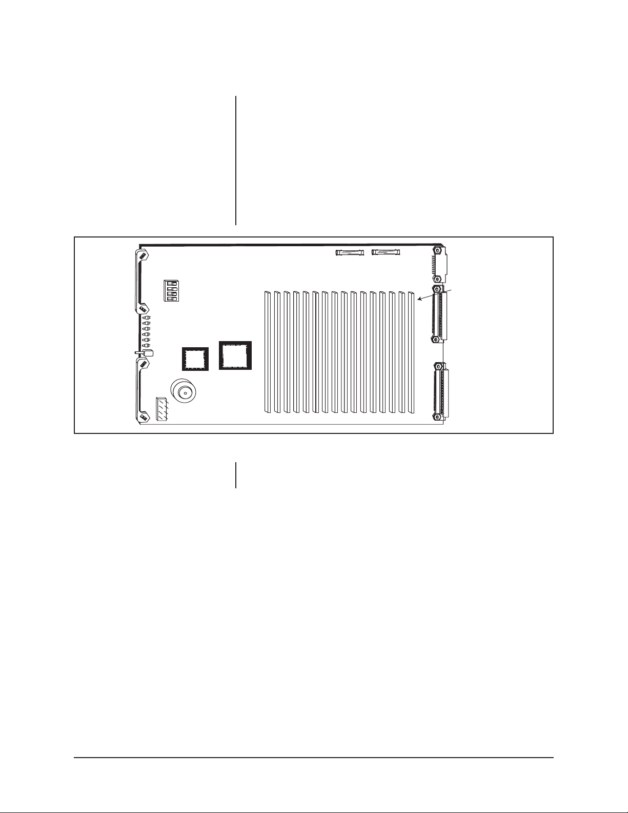
What Does It Look Like?
The Rear Panel Input BNC Card is illustrated in Figure 16.
2
3
TERMINATED
1
JP1-JP16
DOWNFRAME
CONNECTOR
UNTERMINATED
Figure 16. CM9760-RPC Rear Panel BNC Input Card
16 VIDEO INPUT BNCs
What Are Its Functions?
The RPC card handles Video Input to the matrix bay. From 1 to 16 cards can occupy a single matrix bay. Each card has 16 BNC inputs. When the multiplication is
done, up to 256 Video Inputs are available on a fully populated matrix bay. Each
front loaded Video Input Card requires that a corresponding Rear Panel Input BNC
card (CM9760-RPC) be installed.
The RPC card serves several functions:
1. Physical connection point for Coax Cable.
2. The Rear Panel BNC Input Card passes the external Video signal to the Video
Input card.
3. All 16 Input Video Signals are also made available at the 16-pin connector canted
at an angle and located toward the bottom of the board (refer to Figure 16).
4. Video Input Signals can also be terminated, if applicable, with individual jumpers
accessible on the board at each of the 16 video inputs (refer to Figure 16).
24 Pelco Manual C543M-A (7/03)
Page 25

Note the following about the termination jumpers on the RPC card:
• In a single-bay configuration (up to 256 cameras and 16 monitors), the jump-
ers on the RPC card must be set in the terminated position. Refer to Section
5.1 for an illustration of a single-bay configuration.
• In a downframe configuration, the jumpers on the RPC card must be set in the
unterminated position. Refer to Section 5.1 for information about downframing.
• In a sideframe configuration, the jumpers on the RPC card must be set in the
unterminated position. Refer to Section 5.2 for information about sideframing.
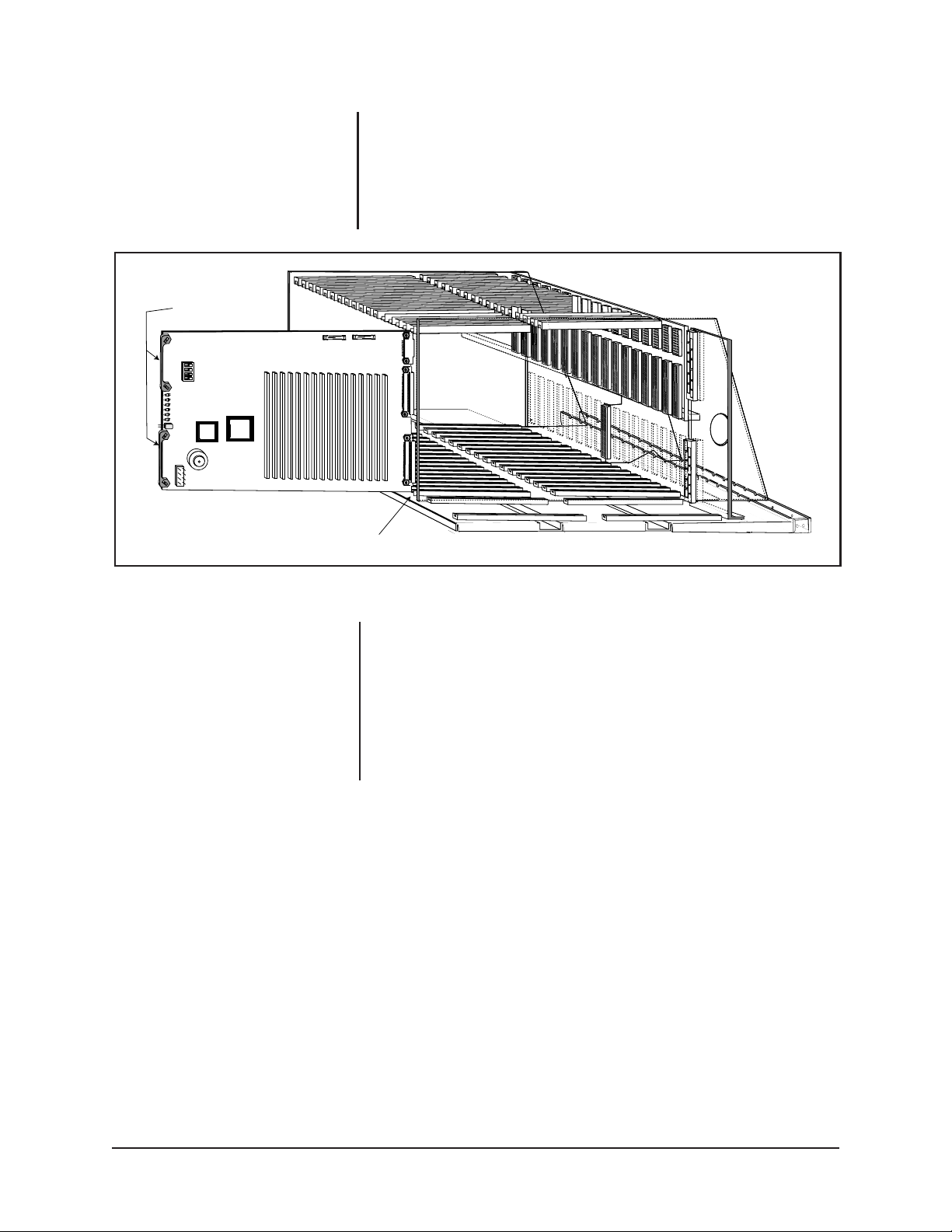
Where Is It Installed?
The Rear Panel Video Input Card is installed from the rear of the matrix bay in any
1 of 16 possible slot positions depending on your system configuration. Remember
that each RPC card is associated with a corresponding Video Input Card. Locate
the correct slot position and install the card as shown. Refer to Figure 17 for typical
installation geometry.
Figure 17. Installation of RPC Input Card
Pelco Manual C543M-A (7/03) 25
Page 26

CM9760-DFL (Rear Panel Downframe Looping Card)
What Does It Look Like?
The DFL card is essentially an RPC card with an attached downframing cable. The
card itself looks like the one pictured in Figure 16.
What Are Its Functions?
The DFL card is used in the last bay in a downframe configuration and provides the
capability to loop out video. The card contains termination jumpers that must be set
in the unterminated position when looping to another device is required. When
looping is not required, the termination jumpers must be set in the terminated position.
The DFL card can be used in the CM9760-MXB to increase the number of available
monitors whether or not looping is required. In addition, the DFL card is the only
card that can be used in the CM9760-MXBL, which is an unpowered, downframed
matrix bay that contains 16 DFL card slots for supporting 256 video loop-out connections. (When looping is required in a 9760 system that has 16 or fewer monitors
and more than 128 cameras, the CM9760-MXBL containing DFLs must be used.)
For additional information about the DFL card, refer to Section 5.1.
Where Is It Installed?
Physically (as long as function parameters are met), a DFL card can be installed in
any slot position.
26 Pelco Manual C543M-A (7/03)
Page 27

CM9760-DFC (Rear Panel Downframe Card, No Looping)
What Does It Look Like?
The DFC card is illustrated in Figure 18.
Note that instead of BNC connectors on the spine of the card there are two identical
16-pin male connectors. Note that there are termination jumpers on the board. Also
note that there is no connector located on the bottom area of the board as was the
case for previously illustrated rear panel cards. The DFC card is supplied with a
downframing cable.
What Are Its Functions?
The downframe card’s almost sole function is as its name implies — to provide a
signal path for the addition of more monitors in extended framing situations while at
the same time aiding full cross-point functionality of the downframed configuration.
For every bay between the first and last, a DFC card is used to interconnect the
associated intermediate bays. The DFC card can also be used in the last bay in a
downframe configuration. Note that when the DFC card is used in the intermediate
bays, the termination jumpers must be set in the unterminated position. When the
DFC card is used in the last bay in a downframe configuration, the termination
jumpers must be set in the terminated position.
Where Is It Installed?
It is installed in any of the 16 slot positions of any bay in a downframing configuration where it is needed. It is physically installed in the same manner as any other
rear panel card. For additional information, refer to Section 5.1 on downframing.
UNTERMINATED
3
2
1
TERMINATED
JP
1
Figure 18. DFC Card
INPUT
FROM BAY ABOVE
JP
16
OUTPUT
TO BAY BELOW
Pelco Manual C543M-A (7/03) 27
Page 28

CM9760-RPL (Rear Panel Localized Looping Within the
Same Matrix Bay)
What Does It Look Like?
The RPL card is illustrated in Figure 19.
Note the double row of BNC connectors running down the spine of the card. Also
note that the card takes up two slot positions instead of one and that the card
contains termination jumpers. The jumpers must be set in the unterminated position when looping functions are required. When looping functions are not required,
the jumpers must be set in the terminated position.
What Are Its Functions?
The RPL card provides a convenient solution for those installations where looping
functions are desired and the total number of camera or video signal inputs for
looping does not exceed 128. Since each card takes up two slot positions, you
have only half of the normally available 256 inputs available for looping. Note that
only odd slot positions (in a fully populated bay) would be occupied and that the
corresponding front loaded Video Input card would also occupy odd slot positions.
Where Is It Installed?
In the same manner as RPC cards, but where looping functions are desirable.
UNTERMINATED
TERMINATED
2
3
JP1-JP16
IN
OUT
1
16 BNC PAIRS
Figure 19. RPL Card
28 Pelco Manual C543M-A (7/03)
Page 29

CM9760-RPM (Rear Panel Output BNC Card for CM9760-VMC)
What Does It Look Like?
The CM9760-RPM rear panel output card is associated with the CM9760-VMC
card. Note that the RPM card contains termination jumpers that must always be set
in the unterminated position. The device to which the RPM card passes its signal is
the point where termination should take place (e.g., a monitor).
What Are Its Functions?
1. Provides signal path for Video Output Card
2. Provides physical BNC connection for external use of Video signal (monitor,
VCR, etc.)
Where Is It Installed?
The card is slot specific and MUST always be installed in the rear position that
corresponds to the front loaded Video Output Card position as viewed from the
front of the matrix bay, which is
slot 17 (refer to Figure 11 or 14).
UNTERMINATED
TERMINATED
2
3
1
16 VIDEO INPUT BNCs
JP1-JP16
DOWNFRAME
CONNECTOR
Figure 20. CM9760-RPM Video Output Card
Pelco Manual C543M-A (7/03) 29
Page 30

2.2.5 Power Supply
Note that the power supply bays are on the right side of the unit (one directly above
the other). An installed power supply is characteristically identified by its handle
and the four LEDs on its front plate. An unoccupied power supply bay is covered
with a blank-off plate as previously shown in Figure 1.
Installing an Additional or Redundant Power Supply
The matrix bay accepts two separate power supplies. When shipped, unless specified otherwise, the unit has one power supply installed. The other location has a
blank-off plate installed. To install an additional power supply, remove the blank-off
plate, line up the supply in the mounting rails and slide into place. Press firmly on
the front of the supply to properly seat the supply into the rear connector (refer to
Figure 21).
Figure 21. Power Supply Installation
30 Pelco Manual C543M-A (7/03)
Page 31

Setting the Jumper on the Power Supply (Beeper Enable)
Located on the power supply is a three-position header that allows the user to
enable/disable the audio beeper, which also is located on the power supply. The
beeper operates in conjunction with the fault LEDs located on the front panel. Refer
to Figure 22 for the location of X5 and how to set the jumper.
Power Supply LEDs
Each power supply is equipped with four LEDs labeled +10 V, -10 V, Frame Fault
and Supply Fault. If the unit is operating properly, the +10 V and -10 V LEDs will be
illuminated. Refer to Table H in Section 3.4.1 for a complete description of the
power supply LEDs.
X5
BEEPER ENABLED
BEEPER DISABLED
Figure 22. Jumper Position on Bottom of Power Supply
Pelco Manual C543M-A (7/03) 31
Page 32

3.0 INSTALLATION
NOTE:
Make sure the selected location has adequate power available.
The unit operates on either 120 VAC
or 230 VAC input power.
3.1 MOUNTING INSTRUCTIONS
The matrix bay communicates with the Controller via RS-422 communications and
therefore can be installed up to 4,000 feet (1,219.2 meters) away from the Controller. Determine where the matrix bay is to be located and follow the mounting and
wiring instructions below.
The matrix bay mounts in a 19-inch rack using standard mounting hardware and
occupies 6 RU (10.5 inches) of vertical space. Place the matrix bay in the desired
location and secure properly.
The matrix bay is designed for low power consumption and therefore has no internal
fans. If mounting several matrix bays together in the same location or if installing in
high temperature environments, it is highly recommended that you separate the
units by at least 1 RU (1.75 inches). In high temperature environments, it also may
be necessary to provide forced air cooling. Contact Pelco for additional information.
Once the unit has been secured into the equipment rack, remove the front panel of
the unit to gain access to the circuit cards. Ensure each card is firmly seated in the
frame.
Figure 23. Mounting the Matrix Bay
32 Pelco Manual C543M-A (7/03)
Page 33

3.2 CONNECTING POWER TO THE MATRIX BAY
WARNING:
Always
replace blown fuses
with fuses of the same
rating. Failure to do so
could result in serious
damage to the unit.
The matrix bay is shipped from the factory configured for the correct input power.
The unit provides two separate power input receptacles, one for each power supply.
Each receptacle is equipped with its own On/Off switch and fuse assembly. In addition, each fuse assembly also provides a spare fuse. Refer to Figure 24. To remove
the fuse assembly, first remove the power cord from the receptacle and, using a
small screwdriver, pry the fuse holder out of the socket. The complete fuse assembly
comes out of the unit. Replace the fuse using a 1.6 ASB fuse. If using the spare,
make sure to replace the spare with one of the same rating.
STORAGE DRAWER
FOR SPARE FUSE
REPLACE IF
NECESSARY
FUSE HOLDER
Figure 24. Replacing Power Supply Fuses
Pelco Manual C543M-A (7/03) 33
Page 34

3.3 CONNECTING THE MATRIX BAY TO THE CONTROLLER
As illustrated in Figure 25, the female RJ-45 SerCom data port connector labeled
RS-422 on the rear of the matrix bay connects to a female RJ-45 SerCom port
(RS-422) on the rear of the CM9760-CC1. A 10-foot (3.05 meters) reversed cable
is supplied to connect the matrix bay to the CC1. If you must create a longer cable,
it is recommended that you use a 24-gauge twisted-pair cable.
CM9760-MXB (FULLY LOADED)
8-PIN SERCOM PORT (FEMALE)
PIN 1
PIN 8
CM9760-MXB CM9760-CC1
CONNECTOR CONNECTOR
PIN 1=Tx+
PIN 2=Tx–
.
.
.
.
PIN 7=Rx–
PIN 8=Rx+
PIN 1=Tx+
PIN 2=Tx–
.
.
.
PIN 7=Rx–
PIN 8=Rx+
REVERSED DATA CABLE (SUPPLIED)
RS-422
DATA CABLE CONNECTIONS
RJ-45 RJ-45
PIN 1=Tx+
PIN 2=Tx–
.
.
.
.
PIN 7=Rx–
PIN 8=Rx+
CM9760-CC1
Figure 25. Connecting the Matrix Bay to the CM9760-CC1 Controller
34 Pelco Manual C543M-A (7/03)
Page 35

3.4 LED DIAGNOSTICS
Each component installed in the matrix bay is equipped with diagnostic LEDs (most
of which have already been mentioned) to aid in system troubleshooting. All LED
assignments are repeated below (for convenience) in Table G.
3.4.1 Performing a Diagnostic LED Check
Prior to connecting any video input or output to the matrix bay, it is recommended
that you first power up the unit to ensure the system is operating properly. Refer to
the following checklist to ensure the matrix bay is operating correctly at this time.
1. Apply power to the unit.
2. Ensure both power LEDs on the supply (or supplies) are illuminated.
3. Ensure both the Frame Fault and the Supply Fault LEDs are OFF.
4. Remove the front panel and check the power LEDs on each of the Video
Input/Output Cards. Both LEDs should be illuminated. If any board has a problem, remove the board(s) and inspect the fuses. Replace fuse (if necessary)
and reinstall into the frame. If the condition continues, replace the defective
board with a known good board.
5. Ensure all Comm Fail LEDs are OFF. If this LED is ON on any Input card,
reseat the board. If the condition continues, replace with a known good board.
If all the Comm Fail LEDs are illuminated, press the reset button located on
the Output card. If the problem continues, replace with a known good board. If
the LED is illuminated on the Output Card only, check the communications to
the CM9750 Controller.
6. If everything is OK, install all video inputs and outputs as described in paragraph 3.5.
Table G. Matrix Bay LED Assignments
Video Output Card LEDs
LED COLOR WHEN LED IS ON
DS1 to DS3 Amber Always ON, No assignment
DS4 Green –10 VDC is OK
DS5 Green +10 VDC is OK
DS6 Red Communications failure with the CM9760-CC1
Video Input Card LEDs
LED COLOR WHEN LED IS ON
CR1 Red Communications failure with the CM9760-CC1
CR2 Green +10 VDC is OK
CR3 Green –10 VDC is OK
Power Supply Module LEDs
LED COLOR WHEN LED IS ON
+10 V Green Normal Operation
–10 V Green Normal Operation
Frame Fault Red (flashing) Failure of one or more cards
Supply Fault Red Failure of associated power supply
3.5 CONNECTING VIDEO INPUTS/OUTPUTS
NOTE:
When wiring inputs it is
always good installation practice to
label each video input. This can save
a considerable amount of time should
All video inputs and monitor outputs are connected to the Rear Panel BNC Cards.
Be sure each connection is secure and that the connectors are installed properly.
When connecting the inputs and outputs to the rear panels, allow enough slack in
the cable to act as a strain relief.
troubleshooting be required.
Pelco Manual C543M-A (7/03) 35
Page 36

4.0 FUNCTIONAL CIRCUIT DESCRIPTION
The matrix bay communicates with the Controller via an RS-422, full-duplex, asynchronous communications interface and performs all video switching functions as
directed from the Controller.
Refer to Figure 26 for a block diagram outlining the discussion in the next few
paragraphs. Refer to Figure 27 for a more graphical representation of the same
thing. The video signal enters the matrix bay through the Rear Panel BNC Card
(Input) where it is terminated with 75 ohms. The signal then proceeds to the Video
Input Card via the input buffers and is then directed to the 16 x 16 crosspoint switch.
Operation of the crosspoint switch is controlled by the Video Output Card.
The signal leaves the Video Input Card and is sent to the Video Output Card via the
video bus. When received by the Video Output Card, the signal is processed by the
Output Titling Module where the DC level of the signal is restored and the titling
message is inserted. The edited video signal leaves the matrix bay through the
Rear Panel BNC Card (Output).
The video signal path is controlled by the microprocessor located on the Video
Output Card. The Video Output Card has full control of all Video Input Cards. The
basic functional group is essentially a crosspoint switch with a variable number of
inputs and 16 outputs. The number of inputs can vary from 16 to 256, in 16 input
increments. The functional group (matrix bay) can be used as a stand alone routing
switcher or it can be connected to other matrix bays to create a larger system.
VIDEO INPUT
VIDEO OUTPUT
REAR PANEL BNC CARD
CM9760-RPC
REAR PANEL BNC CARD
CM9760-RPM
Figure 26. Video Signal Flow–Block Diagram
VIDEO INPUT CARD
INPUT
BUFFER
16 X 16
CROSSPOINT
SWITCH
CM9760-VCC
VIDEO OUTPUT CARD
VIDEO OUTPUT MODULE
CM9760-VMM
CM9760-VMC
36 Pelco Manual C543M-A (7/03)
Page 37

VIDEO INPUT CARD
5 VIDEO OUTPUT BUS
REAR PANEL VIDEO INPUT CARD
4 16x16 CROSSPOINT
3 INPUT BUFFER
2 PATH TO VIDEO CARD AND
TO DOWNFRAME CONNECTOR
1 VIDEO SIGNAL IN
7 OUTPUT TITLING MODULE
6 SIGNAL ON BACKPLANE
ON WAY TO VIDEO
OUTPUT CARD
REAR PANEL
BNC CARD
8 VIDEO
SIGNAL
OUT
Figure 27. Video Signal Flow–Graphical Representation
Pelco Manual C543M-A (7/03) 37
Page 38

CM9760-CC1
5.0 SYSTEM CONFIGURATION–FRAMING
When either more cameras and/or more monitors are needed than can be accommodated by one matrix bay (256 x 16), then one must resort to either downframing
(to increase the number of monitors available for OUTPUT) or to sideframing (to
increase the number of camera INPUTS available).
In order to accommodate these larger systems, additional matrix bays will need to
be installed and it is important to note that this requires that the physical location of
additional matrix bays be within the same rack if you are increasing
bilities, since the expansion requires that the bays be hooked together in a vertical
manner or “downframed”. For downframed configurations, leave 1 RU (1.75 inches)
of space between each matrix bay. Similarly, adding
Inputs requires that additional
matrix bays be located in nearby bays since the expansion occurs in a horizontal
manner called “sideframing”. We shall discuss each configuration separately and
follow that with a discussion of more complicated configurations which involve using
both framing methods in a multi-bay configuration.
Most of the symbolic references and conventions we shall use in our discussion of
system configurations is represented in Figure 28. Items not listed will be labeled
within the illustration itself.
CARD TYPES
MONITOR
Output capa-
CAMERA
CONTROL OR DATA CABLE
MATRIX BAY
SLOT 17
VIDEO OUT/RPM CARD
VIDEO CABLE
Figure 28. System Configuration–Reference Conventions
38 Pelco Manual C543M-A (7/03)
Page 39

5.1 DOWNFRAMING
The matrix bay can be set up in multiple configurations. When limited to 16 monitors
or less, the rear of the bay will be populated by two type of cards: the CM9760-RPC
(Rear Panel BNC card for video inputs, usually a Camera) and the CM9760-RPM
Rear Panel BNC card for Monitor output). These cards are different and are not
(
interchangeable. In addition, on single bay configurations, the jumpers on the
CM9760-RPC cards will be configured for termination–a necessary condition for
operation (refer to Figure 16). A single bay configuration is illustrated in Figure 29.
When it becomes necessary or desirable to downframe, several different scenarios,
each with different card populations, can occur.
Downframing requires that the Inputs of the first bay be electronically reflected or
mirrored in the video circuitry of all other bays downframed from the first. This will
increase, by 16, the number of monitors available for output for each additional bay
downframed.
There are two different available downframe cards, both of which have been discussed previously (refer to Section 2.2.4). One card is the CM9760-DFC (the “no
looping” downframe card) and the other is the CM9760-DFL (the “looping” downframe
card).
JUMPER
SLOT
POSITION 17
16
SLOT POSITIONS
1-16
BAY 1
CARD TYPE
Figure 29. Single Bay Configuration–256 Cameras x 16 Monitors
Pelco Manual C543M-A (7/03) 39
Page 40

Downframing requires that the Video Inputs of the first bay be connected to the
video circuitry of the bay immediately below it. If you remember the physical layout
of the CM9760-RPC card, you will recall that the 16 video inputs to the card are fed
not only to the large, front loaded Video Input Card but are also wired to an output
connector located near the bottom edge of the card. This connector is cocked at an
angle to the bottom matrix bay rear opening for easy access. A downframe cable is
used to connect the bottom connector of the RPC card to either a DFL (looping)
card or a DFC (non-looping) card.
If you are downframing to only one bay, this bay can be populated with DFL or DFC
cards. You will need as many DFL or DFC cards as there are RPC cards in the first
bay. Figure 30 represents downframing with a 256 x 32 multiple matrix bay
configuration that uses DFL cards in the second bay. In this case, the video circuitry
between the first and second bay are tied together, slot for slot, via their bottom
connectors. The termination jumpers on the DFL card in the second or last bay are
in the terminated position only if the loop outs are not connected; the RPC cards in
the first bay are unterminated. In general, termination jumpers on the last downframed
card in a series must be set to the termination setting; however, since an individual
termination jumper exists for each video line, you can route individual video signals
through the DFL card and loop to a monitor output and terminate at that point if you
wish. As a result of downframing operation just described, the Inputs in the first bay
become available to the downframed bay and any input can now be switched to the
additional 16 monitor outputs created there, increasing the total number of monitor
outputs.
JUMPER
J(NT)
J(T)
ONLY TERMINATE
THE INPUTS WHEN
LOOP OUTS ARE
NOT CONNECTED
CARD TYPE
SLOT POSITIONS
1-16
(RIBBON CABLE)
SLOT POSITIONS
1-16
256 VIDEO IN
BAY 1
BAY 2
SLOT
POSITION 17
16
16
32 MONITORS
Figure 30. Single Bay Downframe–256 Cameras x 32 Monitors
40 Pelco Manual C543M-A (7/03)
Page 41

JUMPER CARD TYPE SLOT POSITIONS
DOWNFRAME CABLES
When downframing more than one bay, the intervening bays between the first and
the last contain DFC cards. The last bay in the downframe configuration can contain DFC or DFL cards. Figure 31 illustrates a downframe configuration that uses
DFC cards rather than DFL cards in the last bay.
In Figure 31, note the following:
• The termination jumpers on the RPC cards in the first bay (bay 1) must be in
the unterminated position.
• The termination jumpers on the DFC cards in the intermediate bays (bays 2-7)
must be in the unterminated position.
• The termination jumpers on the DFC cards in the last bay (bay 8) must be in
the terminated position.
SLOT POSITION
17
(VIDEO IN)
BAY 1
BAY 2
BAY 3
BAY 4
BAY 5
BAY 6
BAY 7
BAY 8
128 MONITORS
Figure 31. Downframe Configuration–256 Cameras x 128 Monitors
Pelco Manual C543M-A (7/03) 41
Page 42

5.2 SIDEFRAMING
Factory Configured Systems
When the number of video inputs required exceeds 256, then a method known as
sideframing is used to increase camera input population. This involves tying the
monitor outputs of the first bay to the first 16 video inputs of the sideframed bay.
Figure 32 illustrates one matrix bay sideframed to another.
1-256 IN
257-496 IN
Figure 32. Single Sideframing–496 Cameras x 16 Monitors
42 Pelco Manual C543M-A (7/03)
Page 43

If more video inputs are required than are available with two matrix bays, then, in a
similar manner, additional bays can be sideframed up to a maximum of eight (physically there are nine bays; eight are sideframed to the last bay which is referred to as
the OUTPUT bay). Figure 33 illustrates three sideframed matrix bays and one output bay. When you order an entire system from the factory, all the matrix bays with
their associated boards and connecting cables are tested and properly configured
for your system.
Figure 33. Sideframe Configuration–976 Cameras x 16 Monitors
A Word About Adding Additional Matrix Bays to Existing Field
Installations
If expanding your existing system by sideframing, decouple the monitors connected
to the original bay (leaving the cables connected to the output card, if possible) and
connect these open cables to the first 16 video inputs of the new bay, having it now
become the OUTPUT bay.
This way, the already programmed video inputs for the
original bay can be left alone and all you have to program are the new video inputs.
The same type of scenario applies to any additional matrix bays that are to be
sideframed. As a general rule, to minimize programming time as new bays are
added to a system configuration, they should be installed and configured as the
OUTPUT bay. For example, to continue adding bays to the two bay-configuration
just discussed, decouple the monitor outputs of the existing OUTPUT bay (second
bay) and input them to the second 16 video inputs of the new bay which now becomes
the OUTPUT bay (third bay). Also detach the monitor out cables of the original bay
from the first 16 inputs of the second bay and route them to the first 16 inputs of the
new bay. Doing this, minimizes the amount of reprogramming within your configuration.
Pelco Manual C543M-A (7/03) 43
Page 44

1-256 IN
5.3 DOWNFRAMING/SIDEFRAMING
Combined Sideframing and Downframing
Figure 34 illustrates a matrix bay configuration containing sideframed and downframed bays.
MONITOR 1-16
257-496 IN
*
MONITOR 17-32
*
Figure 34. Sideframe/Downframe Configuration–496 Cameras x 32 Monitors
44 Pelco Manual C543M-A (7/03)
Page 45

TO SLOT 1
TO SLOT 1
TO SLOT 1
Figure 35 illustrates a sideframe/downframe configuration that provides support for
976 cameras and 128 monitors. The configuration consists of a total of 32 matrix
bays.
Figure 36 illustrates a sideframe/downframe configuration that provides support for
2048 cameras and 128 monitors. The configuration consists of a total of 72 matrix
bays.
TO SLOT 2
TO SLOT 2
TO SLOT 2
TO SLOT 3
TO SLOT 3
TO SLOT 3
TO SLOT 1
TO SLOT 1
TO SLOT 1
TO SLOT 1
TO SLOT 1
TO SLOT 2
TO SLOT 2
TO SLOT 2
TO SLOT 2
TO SLOT 2
TO SLOT 3
TO SLOT 3
TO SLOT 3
TO SLOT 3
TO SLOT 3
Figure 35. Sideframe/Downframe Configuration–976 Cameras x 128 Monitors
Pelco Manual C543M-A (7/03) 45
Page 46

1 2 3 4 5 6 7 8
Bay 1
RPCs 1-16
RPM 17
Bay 9
RPCs 1-16
RPM 17
Bay 17
RPCs 1-16
RPM 17
Bay 25
RPCs 1-16
RPM 17
Bay 33
RPCs 1-16
RPM 17
Bay 41
RPCs 1-16
RPM 17
Bay 49
RPCs 1-16
RPM 17
Bay 57
RPCs 1-16
RPM 17
Output
Bay 65
RPM 17
Output
Bay 66
RPM 17
Output
Bay 67
RPM 17
Output
Bay 68
RPM 17
Output
Bay 69
RPM 17
Output
Bay 70
RPM 17
Output
Bay 71
RPM 17
Output
Bay 72
RPM 17
1 2 3 4 5 6 7 8
Bay 2
DFCs 1-16
RPM 17
Bay 10
DFCs 1-16
RPM 17
Bay 18
DFCs 1-16
RPM 17
Bay 26
DFCs 1-16
RPM 17
Bay 34
DFCs 1-16
RPM 17
Bay 42
DFCs 1-16
RPM 17
Bay 50
DFCs 1-16
RPM 17
Bay 58
DFCs 1-16
RPM 17
1 2 3 4 5 6 7 8
Bay 3
DFCs 1-16
RPM 17
Bay 11
DFCs 1-16
RPM 17
Bay 19
DFCs 1-16
RPM 17
Bay 27
DFCs 1-16
RPM 17
Bay 35
DFCs 1-16
RPM 17
Bay 43
DFCs 1-16
RPM 17
Bay 51
DFCs 1-16
RPM 17
Bay 59
DFCs 1-16
RPM 17
1 2 3 4 5 6 7 8
Bay 4
DFCs 1-16
RPM 17
Bay 12
DFCs 1-16
RPM 17
Bay 20
DFCs 1-16
RPM 17
Bay 28
DFCs 1-16
RPM 17
Bay 36
DFCs 1-16
RPM 17
Bay 44
DFCs 1-16
RPM 17
Bay 52
DFCs 1-16
RPM 17
Bay 60
DFCs 1-16
RPM 17
1 2 3 4 5 6 7 8
Bay 5
DFCs 1-16
RPM 17
Bay 13
DFCs 1-16
RPM 17
Bay 21
DFCs 1-16
RPM 17
Bay 29
DFCs 1-16
RPM 17
Bay 37
DFCs 1-16
RPM 17
Bay 45
DFCs 1-16
RPM 17
Bay 53
DFCs 1-16
RPM 17
Bay 61
DFCs 1-16
RPM 17
1 2 3 4 5 6 7 8
Bay 6
DFCs 1-16
RPM 17
Bay 14
DFCs 1-16
RPM 17
Bay 22
DFCs 1-16
RPM 17
Bay 30
DFCs 1-16
RPM 17
Bay 38
DFCs 1-16
RPM 17
Bay 46
DFCs 1-16
RPM 17
Bay 54
DFCs 1-16
RPM 17
Bay 62
DFCs 1-16
RPM 17
1 2 3 4 5 6 7 8
Bay 7
DFCs 1-16
RPM 17
Bay 15
DFCs 1-16
RPM 17
Bay 23
DFCs 1-16
RPM 17
Bay 31
DFCs 1-16
RPM 17
Bay 39
DFCs 1-16
RPM 17
Bay 47
DFCs 1-16
RPM 17
Bay 55
DFCs 1-16
RPM 17
Bay 63
DFCs 1-16
RPM 17
1 2 3 4 5 6 7 8
TO
SLOT 1
TO
SLOT 2
TO
SLOT 3
TO
SLOT 4
TO
SLOT 5
TO
SLOT 6
TO
SLOT 7
TO
SLOT 8
TO
SLOT 1
TO
SLOT 2
TO
SLOT 3
TO
SLOT 4
TO
SLOT 5
TO
SLOT 6
TO
SLOT 7
TO
SLOT 8
TO
SLOT 1
TO
SLOT 2
TO
SLOT 3
TO
SLOT 4
TO
SLOT 5
TO
SLOT 6
TO
SLOT 7
TO
SLOT 8
TO
SLOT 1
TO
SLOT 2
TO
SLOT 3
TO
SLOT 4
TO
SLOT 5
TO
SLOT 6
TO
SLOT 7
TO
SLOT 8
TO
SLOT 1
TO
SLOT 2
TO
SLOT 3
TO
SLOT 4
TO
SLOT 5
TO
SLOT 6
TO
SLOT 7
TO
SLOT 8
TO
SLOT 1
TO
SLOT 2
TO
SLOT 3
TO
SLOT 4
TO
SLOT 5
TO
SLOT 6
TO
SLOT 7
TO
SLOT 8
TO
SLOT 1
TO
SLOT 2
TO
SLOT 3
TO
SLOT 4
TO
SLOT 5
TO
SLOT 6
TO
SLOT 7
TO
SLOT 8
TO
SLOT 1
TO
SLOT 2
TO
SLOT 3
TO
SLOT 4
TO
SLOT 5
TO
SLOT 6
TO
SLOT 7
TO
SLOT 8
Bay 8
DFCs 1-16
RPM 17
Bay 16
DFCs 1-16
RPM 17
Bay 24
DFCs 1-16
RPM 17
Bay 32
DFCs 1-16
RPM 17
Bay 40
DFCs 1-16
RPM 17
Bay 48
DFCs 1-16
RPM 17
Bay 56
DFCs 1-16
RPM 17
Bay 64
DFCs 1-16
RPM 17
** ******
1 - 256
256 IN
257 - 512
256 IN
513 - 768
256 IN
769 - 1024
256 IN
1025 - 1280
256 IN
128 1 - 1536
256 IN
1537 - 1792
256 IN
1793 - 2048
256 IN
*Can also use DFL
Input
Logical
Number
16
16
16
16
16
16
16
16
46 Pelco Manual C543M-A (7/03)
Figure 36. Sideframe/Downframe Configuration–2048 Cameras x 128 Monitors
Page 47

6.0 PROGRAMMING NOTES–ODDS AND ENDS
The following programming notes are brief and are put here only as an indication of
the areas of programming that affect the matrix bay or as a “memory check” for
those already familiar with programming. The following should not be used as a
substitute for the programming manual itself, which should be consulted whenever
any programming changes or additions of substance are made.
Video Loss
Alarm and video modes of Video loss will not be activated unless the fourth switch
position of the S2 switch on the Output card for the matrix bay in which the associated
camera is located is set to ON. It is-by default-in the OFF position.
Video Matrix Bay Numbering (Sideframing)
The Current operating software allows sideframing, of up to eight additonal matrix
bays besides the first, making the total available input capacity of sideframed matrix
bays, 2048. This input capacity increases via the networking of multiple systems.
When programming the COMMS Setup dialog box (.SCP file) as part of programming
your configuration files, there is an entry field for Equipment numbers to be entered
for all devices tied to SerCom ports on the CM9760-CC1. The matrix bay is no
exception; therefore, each matrix bay used in a system must be attached to a communication port on the CC1. Whenever only “one” video matrix bay is attached to a
CC1, you must assign an equipment number of 2 to the port where it’s connected.
If another bay is attached to a different port on the CC1 and is the first sideframed
bay, the port where its connected is assigned an equipment number of 12 in the
equipment field. Likewise, a second and third sideframing bay are assigned Equipment Numbers of 22 and 32, respectively.
Adding a Video Matrix Bay Directly to an Existing System
The following is a quick reference for using 9760 Configuration Setup files to add a
matrix bay to a 9760 System.
1. Click on the Setup icon on the toolbar so that the Configuration files dialog box
appears on the screen (refer to Figure 37).
2. Select the node you wish to edit.
3. Click on “Setup Files” and the Setup File dialog box should appear on screen;
select COMMS (refer to Figure 38).
4. In the Comms Setup dialog box that appears on screen, type the appropriate
Equipment number in the Equipment Number Box (in our example, we entered
the number 2), depending on what you plan to do with the matrix bay (i.e.,
downframe, sideframe).
5. Type in the baud rate and parity.
6. Enter any descriptive information you wish and click on Save.
7. Make sure directly and indirectly associated setup file Dialog boxes are also
configured to reflect the changes made. In most cases these would be Camera
Pelco Manual C543M-A (7/03) 47
Page 48

Configuration Files
PELCO
Node 1
Update Hard Drive
Config Name
Pelco
Setup Files
Close
Node Number
1
Add Node
Figure 37. Setup File Dialog Box with Comms Tab Opened
Figure 38. Configuration File Dialog Box
48 Pelco Manual C543M-A (7/03)
Page 49

Logical Numbering
It can be difficult and confusing to track large numbers of video input and output
signals in a 9760 system. The “logical number” programming field that exists within
the input/output configuration files of affected devices exists as an aid to minimize
this problem for the programmer as well as for the operator of the system. A logical
number is a user selectable, variable number, and is always associated with an
actual physical input, while physical input numbers, in turn, represent an actual
BNC input on the rear of the matrix bay and each input has a given, fixed number
associated with it. However,
level
, it is the logical number that is used for reference; therefore, a judicious
choice for logical numbers can help minimize camera/monitor tracking.
Example 1:
As an example of “logical number” use, let’s assume that on each floor of a 5-story
building there exists a camera population ranging from a minimum of 5 to a maximum
of 10 cameras. The camera population might be as follows:
Floor 1: 5 Cameras
Floor 2: 7 Cameras
Floor 3: 10 Cameras
Floor 4: 6 Cameras
Floor 5: 5 Cameras
Can logical numbers be assigned to each of the camera inputs connected to the
matrix bay in the above list a way that would help the operator to track cameras
location?
Let’s assume that logical numbers for the above are assigned according to the
following rules:
within the programming environment and at the operator
(1) Each logical number that references a camera input consists of three digits.
(2) The first digit gives the floor level of the camera location.
(3) The next two digits identify the camera location on the referenced floor accord-
ing to some previously agreed upon sequence.
Looking at floor 4, for example, the physical inputs for the 6 cameras might be
assigned sequential logical numbers 401, 402, 403, 404, 405 and 406; however, if
one wished to allow for future expansion between existing camera locations, the
assigned logical numbers might be assigned with a 5 unit spacing between numbers
and end up with assigned logical numbers of 401, 405, 410, 415, 420, and 425,
respectively. To put a different twist on logical number assignment, let’s assume
that each floor covered a large area, then our “rule three” above might be modified
to let the last two digits represent a division of the floor area into zones; with the
second digit being one of 9 possible zones and the third digit being 1 of 9 possible
cameras within any given zone. The point of all this is, is that there are many and
varied ways to assign logical numbers-it just should be done in a way that makes
sense for your installation.
Pelco Manual C543M-A (7/03) 49
Page 50

Example 2:
At other times, it might be useful to define the logical number of a camera input as
being the same as that of the actual physical, fixed input that the camera is attached
to. Since physical inputs and their associated numbers are fixed, it seems like a
natural choice, under some circumstances, to use this scheme. Figure 39 shows a
camera file set up where the numbers entered for the physical input and the logical
field are the same.
Figure 39. Camera Files and Logical Numbers
50 Pelco Manual C543M-A (7/03)
Page 51

Physical
Input
Numbers
This happy state of sequential ordering breaks down if an additional bay is added
(sideframed) to increase camera inputs (refer to Figure 40). This is because the 16
video output cables (from the CM9760-RPM cards) of the original bay are connected to the first 16 video inputs of the sideframed bay (CM9760-RPC cards).
These 16 inputs, which are still physical inputs (but dedicated to another purpose)
are not available as independent physical inputs at the operator level and in the
logical field associated with these inputs, a “0” must be entered.
Logical
Field
Numbers
Figure 40. Physical and Logical Numbers Compared
Pelco Manual C543M-A (7/03) 51
Page 52

The next 16 inputs of the sideframed bay, however, are available for programming
at the operator level and logical numbers can be assigned; so what number should
we use? Using 273 in the logical field would introduce a numbering gap of 16 in the
sequential ordering of camera inputs (the last logical/physical number pairing was
256 in the original matrix bay). The best solution is to ignore the gap and pick up the
count at 257 (refer to Figure 41). This, at least, preserves the sequential ordering of
camera numbering. It should also be pointed out that if sideframing had been necessary in our first example, then the comments made here about logical numbering
would also apply.
Figure 41. Physical/Logical Numbers, Sideframed Bays and Camera Files
52 Pelco Manual C543M-A (7/03)
Page 53

7.0 SYSTEM TROUBLESHOOTING
If there is a problem with the matrix bay, first try pressing the reset button located on
the front of the Video Output Card. This will reset the operation of the matrix bay
and reload all information such as camera and monitor idents, etc. from the Controller. If this does not correct the problem, refer to various sections within this
manual as well as other System 9760 documentation to try to isolate and resolve
the problem. If still unsuccessful, contact Pelco for assistance.
Pelco Manual C543M-A (7/03) 53
Page 54

CM9760-MXB
Electrical
Input Voltage: 120 VAC, 60 Hz or 230 VAC, 50 Hz
Power
Consumption: 90 watts maximum (fully populated)
Communication: Full duplex RS-422 using an RJ-45 connector
Video Inputs: Sixteen input card slots for supporting 256 inputs per bay
Video Outputs: One output card slot for supporting 16 outputs per bay
Video Input Level: .5 to 2 Vp-p, RS-170 composite video
Impedance: 75 ohms terminating (looping versions available)
Crosstalk: -60 dB at 3.58 MHz
General
Operating
Temperature: 14° to 122°F (-10° to 50°C)
8.0 SPECIFICATIONS
Dimensions: 19.0 (W) x 10.5 (H) x 20.0 (D) inches
Mounting: Fits 19-inch EIA Standard rack (6 RUs)
Unit Weight: 32.0 lb (14.55 kg)
CM9760-MXBL
Electrical
Input Voltage: None (passive looping assembly)
Power
Consumption: None
Communication: None
Video Outputs: Sixteen DFL card slots for supporting 256 looping outputs
General
Dimensions: 19.0 (W) x 10.5 (H) x 20.0 (D) inches
Mounting: Fits 19-inch EIA Standard rack (6 RUs)
Unit Weight: 24.2 lb (11.00 kg)
(48.26 x 26.67 x 50.80 cm)
52.9 lb (24.05 kg), fully populated
(48.26 x 26.67 x 50.80 cm)
35.4 lb (16.1 kg), fully populated
(Design and product specifications subject to change without notice.)
54 Pelco Manual C543M-A (7/03)
Page 55

9.0 WARRANTY AND RETURN INFORMATION
WARRANTY
Pelco will repair or replace, without charge, any merchandise proved defective in material or
workmanship for a period of one year after the date of shipment. Exceptions to this warranty
are as noted below:
• Five years on Pelco manufactured cameras (CC3500/CC3600/CC3700 and MC3500/
MC3600 Series); two years on all other cameras.
• Three years on Genex
Camclosure
•Two years on 100/150, 200 and 300 Series Camclosure
•Two years on all standard motorized or fixed focal length lenses.
•Two years on Legacy®, CM6700/CM6800/CM8500/CM9500/CM9740/CM9760 Matrix, DF5
and DF8 Series Fixed Dome products.
•Two years on Spectra
motion applications.
•Two years on Esprit and WW5700 series window wiper (excluding wiper blades).
• Eighteen months on DX Series digital video recorders.
• One year (except video heads) on video cassette recorders (VCRs). Video heads will be
covered for a period of six months.
• Six months on all pan and tilts, scanners or preset lenses used in continuous motion
applications (that is, preset scan, tour and auto scan modes).
Pelco will warrant all replacement parts and repairs for 90 days from the date of Pelco shipment. All goods requiring warranty repair shall be sent freight prepaid to Pelco, Clovis, California. Repairs made necessary by reason of misuse, alteration, normal wear, or accident are not
covered under this warranty.
Pelco assumes no risk and shall be subject to no liability for damages or loss resulting from the
specific use or application made of the Products. Pelco’s liability for any claim, whether based
on breach of contract, negligence, infringement of any rights of any party or product liability,
relating to the Products shall not exceed the price paid by the Dealer to Pelco for such Products. In no event will Pelco be liable for any special, incidental or consequential damages
(including loss of use, loss of profit and claims of third parties) however caused, whether by the
negligence of Pelco or otherwise.
The above warranty provides the Dealer with specific legal rights. The Dealer may also have
additional rights, which are subject to variation from state to state.
If a warranty repair is required, the Dealer must contact Pelco at (800) 289-9100 or (559) 2921981 to obtain a Repair Authorization number (RA), and provide the following information:
1. Model and serial number
2. Date of shipment, P.O. number, Sales Order number, or Pelco invoice number
3. Details of the defect or problem
If there is a dispute regarding the warranty of a product which does not fall under the warranty
conditions stated above, please include a written explanation with the product when returned.
Method of return shipment shall be the same or equal to the method by which the item was
received by Pelco.
®
Camera System.
®
Series (multiplexers, server, and keyboard) and 090 Series
®
, Esprit®, and PS20 Scanners, including when used in continuous
®
Camera Systems.
RETURNS
In order to expedite parts returned to the factory for repair or credit, please call the factory at
(800) 289-9100 or (559) 292-1981 to obtain an authorization number (CA number if returned
for credit, and RA number if returned for repair).
All merchandise returned for credit may be subject to a 20% restocking and refurbishing charge.
Goods returned for repair or credit should be clearly identified with the assigned CA or RA
number and freight should be prepaid. Ship to the appropriate address below.
® Pelco, the Pelco logo, and System 9760
are registered trademarks of Pelco.
© Copyright 2003, Pelco. All rights reserved.
If you are located within the continental U.S., Alaska, Hawaii or Puerto Rico:
If you are located outside the continental U.S., Alaska, Hawaii or Puerto Rico:
Service Department
Pelco
3500 Pelco Way
Clovis, CA 93612-5699
Intermediate Consignee Ultimate Consignee
American Overseas Air Freight Pelco
320 Beach Road 3500 Pelco Way
Burlingame, CA 94010 Clovis, CA 93612-5699
USA USA
Pelco Manual C543M-A (7/03) 55
Page 56

®
World Headquarters
3500 Pelco Way
Clovis, California 93612 USA
USA & Canada
Tel: 800/289-9100
Fax: 800/289-9150
International
Tel: 1-559/292-1981
Fax: 1-559/348-1120
www.pelco.com
ISO9001
United States | Canda | United Kingdom | The Netherlands | Sinapore | Spain | Scandanavia | France
Middle East
|
 Loading...