

Page 1

ADDENDUM
C547M-B (9/02)
September 2002
Addendum to Installation/User Manual C547M-B
for the CM9760-MGR Software
This addendum covers changes made to the CM9760-MGR in software version 7.80. This software upgrade adds
the following features.
1. Restricting access to cameras so only specified users can view or control them.
2. Control of pan, tilt, and zoom (PTZ) equipment through a Genex® multiplexer.
3. On-screen character blinking to reduce characters “burning in” on the monitor tube.
4. Compatibility with CM9760-SAT satellite switchers.
Future revisions of the manual will include this information. Should you need technical
assistance with this product, please call (800) 289-9100 or (559) 292-1981.
®
Pelco • 3500 Pelco Way • Clovis, CA 93612-5699 • USA • Pelco Online @ http://www.pelco.com
In North America and Canada: Tel (800) 289-9100 • FAX (800) 289-9150 • DataFAX (800) 289-9108
International Customers: Tel (1-559) 292-1981 or FAX (1-559) 348-1120 • DataFAX (1-559) 292-0435
Page 2
1. CAMERA ACCESS
You can create up to 32 groups of cameras and then decide on which monitors the cameras can be viewed and/or which operators
can control cameras with PTZ functions.
1.1. CAMERA ACCESS FOR VIEWING (C/M GROUP)
This feature allows you to create up to 32 groups of cameras and then to assign the groups of cameras to specific monitors for
viewing.
Here is an example of how this feature might be used in an installation:
Cameras 1, 2, 7, 8, and 9 are cameras that the supervisor uses to watch security guards. These cameras cannot be viewed by the
guards on the monitors in the security room but can be viewed on the supervisor’s monitor in his office.
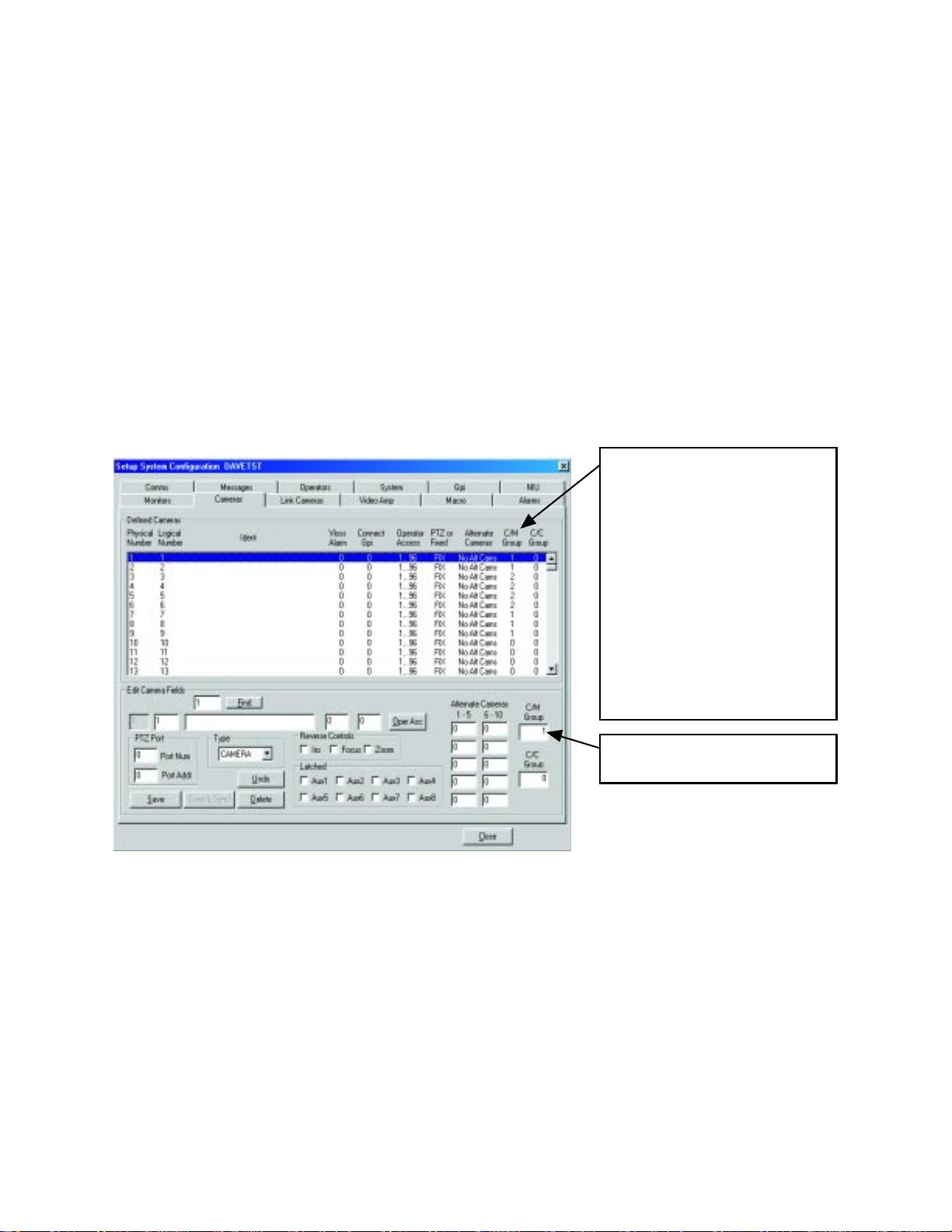
To program camera viewing access:
1. Define the groups of cameras by entering a group number from 1-32 in the C/M Group field for each camera. Each camera can
be assigned to only one group.
C/M Group number identifies the
access group that each camera has
been assigned to.
In this example:
Cameras 1, 2, 7, 8, 9 = group 1
Cameras 3-6 = group 2
Cameras 10-13 = no group
Groups 1 and 2 can now be assigned
to the monitors on which the cameras
can be viewed (refer to step 2).
Cameras that are not assigned to a
group (0 in C/M Group field) will be
visible on all monitors.
The C/M Group number is entered in
this box.
ADDENDUM — (9/02) 1
Page 3
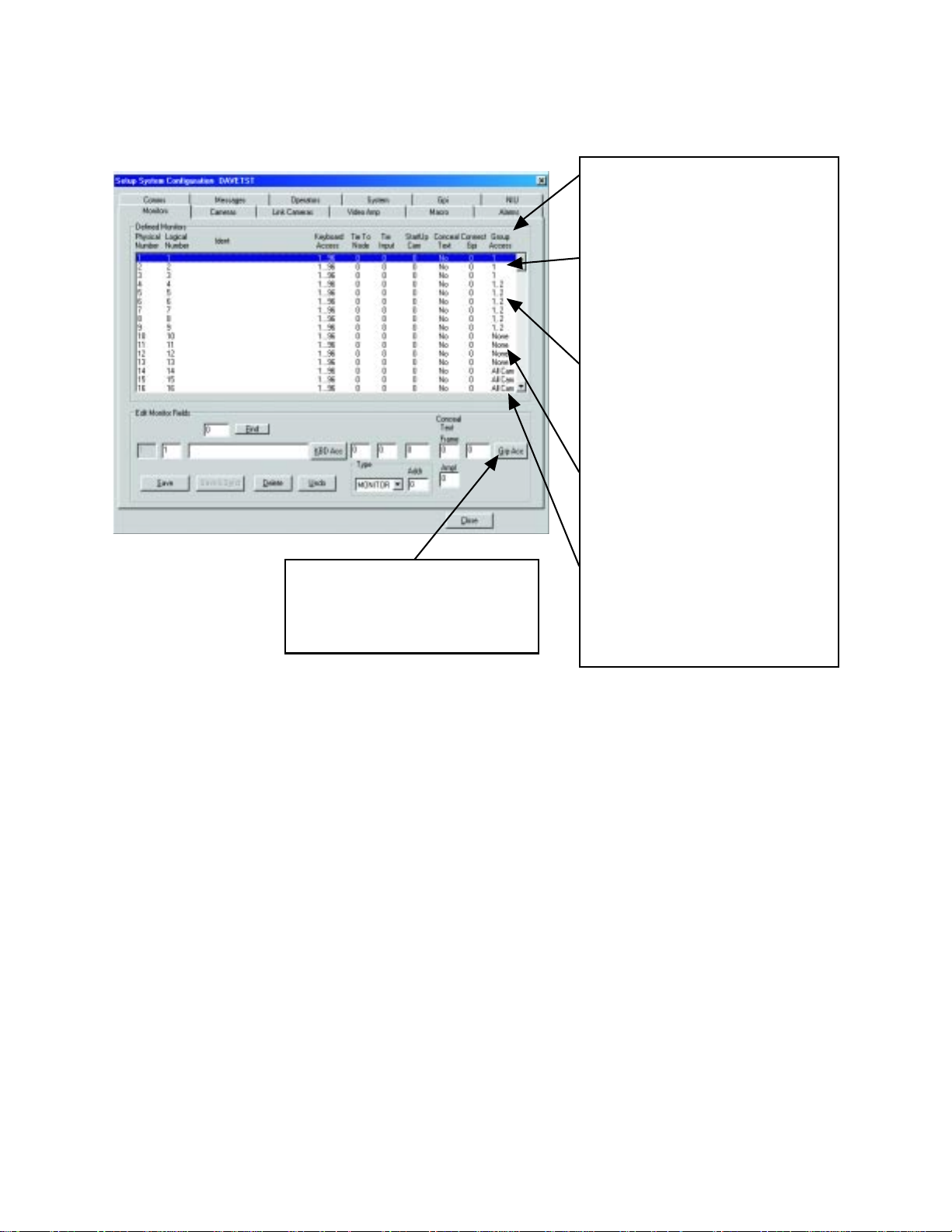
2. Define which camera groups can be viewed on each monitor by entering the group number(s) in the Group Access field.
Group Access identifies the camera groups
that can be viewed on each monitor.
In this example:
Monitors 1-3 can view cameras that have
been assigned to group 1 and any cameras that have not been assigned to a specific group (0 in C/M Group field in step 1).
These monitors cannot view cameras from
any other group; that is, groups 2-32.
Monitors 4-9 can view cameras that have
been assigned to groups 1 and 2 and any
cameras that have not been assigned to a
specific group (0 in C/M Group field in step
1). These monitors cannot view cameras
from any other group; that is, groups 3-32.
Monitors 10-13 can view cameras that
have not been assigned to a specific
group (0 in C/M Group field in step 1).
These monitors cannot view cameras
from any group; that is, 1-32.
To select groups, click the Grp Acc button. The Group Access Table appears.
Click the box in front of the group number
to toggle the X on or off. An X in the box
grants access; no X denies access.
Monitors 14-16 have been given access
to all 32 groups. Therefore, they can view
any camera that has been assigned to a
group (1-32) as well as any camera that
has not been assigned to a group (0 in C/
M Group field in step 1).
2 ADDENDUM — (9/02)
Page 4

1.2 CAMERA ACCESS FOR PTZ CONTROL (C/C GROUP)
This feature allows you to create up to 32 groups of cameras and then to assign the groups of cameras to specific operators for PTZ
control.
Here is an example of how this feature might be used in an installation:
Cameras 1, 2, 3, and 10 are PTZ cameras that the supervisor uses to record activity on a VCR. He wants his guards to be able to
watch these cameras but not to move them. By restricting access he can eliminate the possibility of the guards accidentally moving
the cameras.
To program camera control access:
1. Define the groups of cameras by entering a group number from 1-32 in the C/C Group field for each camera. Each camera can
be assigned to only one group.
C/C group number identifies the access group that each camera has
been assigned to.
In this example:
Cameras 1, 2, 3, 10 = group 1
Cameras 4-9 = group 2
Cameras 11-13 = no group
Groups 1 and 2 can now be assigned
to the operators you want to control
the cameras (refer to step 2).
Cameras that are not assigned to a
group (0 in C/C Group field) can be
controlled by all operators.
The C/C Group number is entered in
this box.
ADDENDUM — (9/02) 3
Page 5

2. Define which operators can control each camera group by entering the group number(s) in the Group Access field.
Group Access identifies the camera groups
that can be controlled by each operator.
In this example:
Operators 1 and 2 can control any camera
that has not been assigned to a specific
group (0 in C/C Group field in step 1). These
operators cannot control cameras assigned
to any group; that is, groups 1-32
Operators 3 and 4 can control any camera
that has been assigned to group 2 and any
cameras that have not been assigned to a
specific group (0 in C/C Group field in step
1). These operators cannot control cameras
assigned to any other group; that is, groups
1 and 3-32.
Operators 5 and 6 can control any camera
that has been assigned to groups 1 and 2
and any cameras that have not been assigned to a specific group (0 in C/C Group
field in step 1). These operators cannot control cameras assigned to any other group;
that is, groups 3-32.
To select groups, click the Grp
Acc button. The Group Access
Table appears. Click the box in
front of the group number to
toggle the X on or off. An X in the
box grants access; no X denies
access.
Operators 7 and 8 can control any camera
that has been assigned to any group
(groups 1-32) and any cameras that have
not been assigned to a specific group (0 in
C/C Group field in step 1).
4 ADDENDUM — (9/02)
Page 6

2. PTZ CONTROL THROUGH A GENEX MULTIPLEXER
To control a multiplexer:
1. With the CM9760-MGR software running, select 9760 SETUP from the tool bar.
2. In the Configuration Files dialog box, click the Cameras tab.
3. In the Defined Cameras window, highlight the line for the physical number of the matrix camera input port where the main
output of the multiplexer is connected.
4. In the Edit Camera Fields window, enter information for all fields as you normally would, but select MULTIPLX for the Type.
5. In the Port Num box enter the number for the CC1 port that goes to the multiplexer. In the Port Addr box enter the Unit ID
Number of the multiplexer. (Unit ID Number is 1 if only one multiplexer is connected to the CC1 port, but is 1 or greater if
several multiplexers are daisy-chained on the same CC1 port.)
6. Multiplexers can be assigned to a C/M Group and/or a C/C Group if you wish to prevent the multiplexer’s video from being
viewed on any monitors or if you wish to exclude any operators from controlling the positioning equipment associated with the
multiplexer’s cameras. Refer to the
7. Save the Camera Setup file and exit.
Camera Access
section of this addendum.
Entering MULTIPLX in the Type
field defines this input as a multiplexer. The multiplexer control icons
will appear on the CM9760-KBD
when this input is selected.
Enter the port number (on the
CM9760 CC1) that this multiplexer
is connected to.
Enter the multiplexer’s Unit ID
Number.
ADDENDUM — (9/02) 5
Page 7

3. ON-SCREEN CHARACTER BLINKING
To reduce the possibility of “burning in” characters on a monitor screen, you can make the Camera ID on the monitors blink.
To set the blink time:
1. With the CM9760-MGR software running, select 9760 SETUP from the tool bar.
2. In the Configuration Files dialog box, click the System tab.
3. Find the Miscellaneous window.
4. In the Ident Blink Timer box enter the number of seconds the camera ID is to be displayed. The off time between the camera ID
appearances will be five to six times longer than the on time. Enter 0 to turn the feature off (camera ID will be displayed all the
time).
5. Save and exit.
The Ident Blink Timer defines the rate
at which the camera ID will blink.
In this example the display will be on
for 20 seconds and off for approximately 100 seconds.
4. COMPATIBILITY WITH CM9760-SAT SATELLITE SWITCHERS
This feature of version 7.8 is supported in the CM9760-SAT (v. 7.8) manual.
6 ADDENDUM — (9/02)
 Loading...