

Page 1

INSTALLATION MANUAL
®
System 9760
®
KBD/KBR Firmware
Upgrade
CM9760-KBD-E80
C1543M-A (7/04)
Page 2

Page 3

INTRODUCTION
The System 9760® keyboard upgrade kit, CM9760-KBD-E80, provides the following items to upgrade CM9760-KBD/CM9760-KBR
firmware to version 8.03:
1 U3 EPROM chip, version 8.03, part number IC53-0043-0803
1 Chip extraction tool, part number ICPULLERTOOL
This manual provides instructions to upgrade CM9760-KBD/CM9760-KBR firmware from version 7.8 or earlier to version 8.03.
To upgrade CM9760-KBD firmware, see the section titled
firmware, see the section titled
Upgrading CM9760-KBD Firmware.
Upgrading CM9760-KBR Firmware.
To upgrade CM9760-KBR
C1543M-A (7/04) 1
Page 4
UPGRADING CM9760-KBD FIRMWARE
CAUTION: Only qualified personnel observing electrostatic discharge (ESD) precautions should perform the procedure
below. Always wear a grounding strap connected to an approved grounding source when working on or near exposed
electronic components. Handle circuit boards by their edges.
To upgrade CM9760-KBD firmware to version 8.03, do the following:
1. Using System Manager, upload user-entered keyboard setup information to the System Manager database.
NOTE: This step is necessary to avoid loss of user-programmed keyboard setup information, which is erased when
the KBD is reset later in this procedure. After the KBD is reset, you can download the setup information from
System Manager to the KBD as directed later in this procedure.
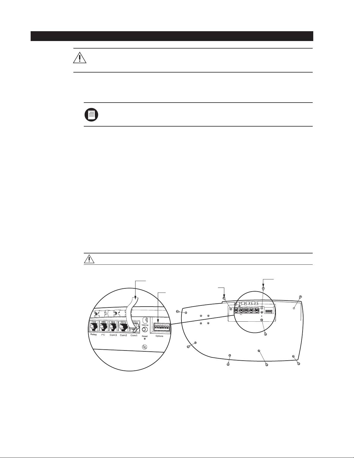
2. Log off the KBD and then turn the KBD over so that the bottom of the KBD is visible (refer to Figure 1).
3. Disconnect the KBD from the 9760 system by unplugging the cable from the COM 1 port of the KBD.
4. Set DIP switch 7 to the correct position:
• For compatibility with CM9760-CC1 and CM9760-MGR versions 7.80.003 to 7.80.029, set DIP switch 7 to the OFF
position.
• For compatibility with CM9760-CC1 and CM9760-MGR version 8.03.006 or later, set DIP switch 7 to the ON position.
5. Remove the bottom cover of the KBD:
a. Unscrew nine Phillips screws as indicated in Figure 1. Note that on some KBDs one of the screws has a plastic
retaining nut as indicated in Figure 1. Remove that screw
To remove the screw that has a plastic retaining nut, do the following:
(1) Lift off the bottom cover of the KBD
(2) Locate the nut and, while holding the nut with your fingers to prevent the nut from turning, remove the screw.
slightly
after
you remove the other eight screws.
.
b. Gently lift off the bottom cover of the KBD.
CAUTION: Be careful not to detach any of the wires that are soldered to the surface of the circuit board.
CABLE
SCREW (9)
DIP SWITCH 7
Relay Com3 Com2 Com1
8
7
6
5
4
3
1
2
NO
Volume
Reset
Figure 1. Bottom of CM9760-KBD
(MAY HAVE
RETAINING
NUT)
Options
2 C1543M-A (7/04)
Page 5

6. Remove the existing U3 EPROM chip (refer to Figure 2) from its socket using the provided extraction tool. Remove the chip
slowly to avoid damaging the socket.
7. Remove the replacement EPROM chip from the electrostatic bag, and inspect the chip to confirm that the pins are
straight.
8. As illustrated in Figure 2, orient the chip using the alignment notch as a guide. Verify pin-to-socket alignment, and then
carefully press the chip into its socket until the chip is completely seated.
9. Reattach the bottom cover to the KBD using the nine Phillips screws.
10. Reset the keyboard to factory default settings by doing the following:
a. With the KBD remaining powered off, set DIP switches 1, 2, and 8 to the ON position.
b. Power on the KBD by reconnecting the cable to the COM 1 port.
The Diagnostics mode display appears.
c. Power off the KBD by disconnecting the cable from the COM 1 port.
d. Set DIP switches 1 and 8 to the OFF position.
e. Power on the KBD by reconnecting the cable to the COM 1 port.
NOTCHED END
OF EPROM
ALIGNMENT
NOTCH
Figure 2. U3 EPROM Chip
U4
U3
U3 EPROM CHIP
U12
U2
U5
CIRCUIT
BOARD
C1543M-A (7/04) 3
Page 6

11. Calibrate the joystick as follows:
a. In Setup mode, select the Joystick Adjust icon.
The Joystick Setup menu appears (refer to Figure 3).
KEYBOARD
SELECT
ICON
MOVE CURSOR/
CYCLE SELECTIONS
LEFT ICON
FORWARD STEP/
SCROLL UP
ICON
MOVE CURSOR/
CYCLE SELECTIONS
BACKWARD STEP/
SCROLL DOWN
RIGHT ICON
ICON
SAVE ICON
EXIT ICON
Figure 3. Joystick Setup Menu
b. With the joystick in the central default position, select the Keyboard Select icon.
c. Verify that the pan and tilt center values (xxx,xxx) are between 122 and 134.
d. Move the joystick fully to the left, and then select the Move Cursor/Cycle Selections Left icon.
e. Verify that the left value is between 90 and 98.
f. Move the joystick fully to the right, and then select the Move Cursor/Cycle Selections Right icon.
g. Verify that the right value is between 158 and 166.
h. Move the joystick fully down, and then select the Backward Step/Scroll Down icon.
i. Verify that the down value is between 90 and 98.
j. Move the joystick fully up, and then select the Forward Step/Scroll Up icon.
k. Verify that the up value is between 158 and 166.
l. Save the joystick configuration by selecting the Save icon.
m. Return to the Setup menu by selecting the Exit icon.
12. Using System Manager, download the keyboard setup information to the KBD.
4 C1543M-A (7/04)
Page 7

UPGRADING CM9760-KBR FIRMWARE
CAUTION: Only qualified personnel observing electrostatic discharge (ESD) precautions should perform the procedure
below. Always wear a grounding strap connected to an approved grounding source when working on or near exposed
electronic components. Handle circuit boards by their edges.
To upgrade CM9760-KBR firmware to version 8.03, do the following:
1. Using System Manager, upload user-entered keyboard setup information to the System Manager database.
NOTE: This step is necessary to avoid loss of user-programmed keyboard setup information, which is erased when
the KBR is reset later in this procedure. After the KBR is reset, you can download the setup information from
System Manager to the KBR as directed later in this procedure.
2. Log off the KBR.
3. Disconnect the KBR from the 9760 system by unplugging the cable from the COM 1 port on the rear of the KBR (refer to
Figure 4).
4. Remove the KBR from the rack by unscrewing the two Phillips rack-mounting screws from each rack ear on the front of
the KBR (refer to Figure 5).
FLAT HEAD SCREW (16)
DIP SWITCH 7
PAN HEAD SCREW (4)
2
Relay I
C
RACK-MOUNTING
SCREW (4)
Volume
Options
Relay
I2C
8
7
6
5
3
4
1
Options
2
NO
Volume
Com
3
Com2
Com1
Reset
Reset
Com3
Com1
Com2
CABLE
Figure 4. Rear of CM9760-KBR
RACK
Figure 5. Front of CM9760-KBR
C1543M-A (7/04) 5
Page 8

T
5. Locate DIP switch 7 on the rear of the KBR (refer to Figure 4), and set the DIP switch to the correct position:
• For compatibility with CM9760-CC1 and CM9760-MGR versions 7.80.003 to 7.80.029, set DIP switch 7 to the OFF
position.
• For compatibility with CM9760-CC1 and CM9760-MGR version 8.03.006 or later, set DIP switch 7 to the ON position.
6. Remove the rear panel of the KBR by unscrewing 16 flat head and 4 pan head Phillips screws (5 flat head screws on top
of panel, 5 flat head screws on bottom of panel, 3 flat head screws on each side of panel, and 4 pan head screws on face
of panel).
7. Remove the existing U3 EPROM chip (refer to Figure 6) from its socket using the provided extraction tool. Remove the chip
slowly to avoid damaging the socket.
8. Remove the replacement EPROM chip from the electrostatic bag, and inspect the chip to confirm that the pins are
straight.
9. As illustrated in Figure 6, orient the chip using the alignment notch as a guide. Verify pin-to-socket alignment, and then
carefully press the chip into its socket until the chip is completely seated.
10. Reattach the rear panel of the KBR using the 16 flat head and 4 pan head Phillips screws.
11. Reset the keyboard to factory default settings by doing the following:
a. With the KBR remaining powered off, set DIP switches 1, 2, and 8 to the ON position.
b. Power on the KBR by reconnecting the cable to the COM 1 port.
The Diagnostics mode display appears.
NOTCHED END
OF EPROM
ALIGNMENT
NOTCH
c. Power off the KBR by disconnecting the cable from the COM 1 port.
d. Set DIP switches 1 and 8 to the OFF position.
e. Power on the KBR by reconnecting the cable to the COM 1 port.
U4
U3
U3 EPROM CHIP
Figure 6. U3 EPROM Chip
U12
U2
U5
CIRCUI
BOARD
6 C1543M-A (7/04)
Page 9

12. Calibrate the joystick as follows:
a. In Setup mode, select the Joystick Adjust icon.
The Joystick Setup menu appears (refer to Figure 7).
KEYBOARD
SELECT
ICON
MOVE CURSOR/
CYCLE SELECTIONS
LEFT ICON
FORWARD STEP/
SCROLL UP
ICON
MOVE CURSOR/
CYCLE SELECTIONS
BACKWARD STEP/
SCROLL DOWN
RIGHT ICON
ICON
SAVE ICON
EXIT ICON
Figure 7. Joystick Setup Menu
b. With the joystick in the central default position, select the Keyboard Select icon.
c. Verify that the pan and tilt center values (xxx,xxx) are between 122 and 134.
d. Move the joystick fully to the left, and then select the Move Cursor/Cycle Selections Left icon.
e. Verify that the left value is between 90 and 98.
f. Move the joystick fully to the right, and then select the Move Cursor/Cycle Selections Right icon.
g. Verify that the right value is between 158 and 166.
h. Move the joystick fully down, and then select the Backward Step/Scroll Down icon.
i. Verify that the down value is between 90 and 98.
j. Move the joystick fully up, and then select the Forward Step/Scroll Up icon.
k. Verify that the up value is between 158 and 166.
l. Save the joystick configuration by selecting the Save icon.
m. Return to the Setup menu by selecting the Exit icon.
13. Mount the KBR into the rack, and attach each rack ear of the KBR to the rack using two Phillips rack-mounting screws for
each ear.
14. Using System Manager, download the keyboard setup information to the KBR.
C1543M-A (7/04) 7
Page 10

Page 11

WARRANTY AND RETURN INFORMATION
WARRANTY
Pelco will repair or replace, without charge, any merchandise proved defective in material
or workmanship for a period of one year after the date of shipment.
Exceptions to this warranty are as noted below:
• Five years on the following fixed camera models: CC3701H-2, CC3701H-2X, CC3751H-2,
CC3651H-2X, MC3651H-2, and MC3651H-2X.
• Three years on all other fixed camera models (including Camclosure® Integrated
Camera Systems) and Genex® Series (multiplexers, server, and keyboard).
•Two years on all standard motorized or fixed focal length lenses.
•Two years on Legacy®, CM6700/CM6800/CM8500/CM9500/CM9700 Series Matrix,
DF5 and DF8 Series Fixed Dome products.
•Two years on Spectra®, Esprit®, and PS20 Scanners, including when used in continuous
motion applications.
•Two years on Esprit® and WW5700 series window wiper (excluding wiper blades).
• Eighteen months on DX Series digital video recorders and NVR300 network video
recorders.
• One year (except video heads) on video cassette recorders (VCRs). Video heads will be
covered for a period of six months.
• Six months on all pan and tilts, scanners or preset lenses used in continuous motion
applications (that is, preset scan, tour and auto scan modes).
Pelco will warrant all replacement parts and repairs for 90 days from the date of Pelco
shipment. All goods requiring warranty repair shall be sent freight prepaid to Pelco, Clovis,
California. Repairs made necessary by reason of misuse, alteration, normal wear, or
accident are not covered under this warranty.
Pelco assumes no risk and shall be subject to no liability for damages or loss resulting from
the specific use or application made of the Products. Pelco’s liability for any claim, whether
based on breach of contract, negligence, infringement of any rights of any party or product
liability, relating to the Products shall not exceed the price paid by the Dealer to Pelco for
such Products. In no event will Pelco be liable for any special, incidental or consequential
damages (including loss of use, loss of profit and claims of third parties) however caused,
whether by the negligence of Pelco or otherwise.
The above warranty provides the Dealer with specific legal rights. The Dealer may also
have additional rights, which are subject to variation from state to state.
If a warranty repair is required, the Dealer must contact Pelco at (800) 289-9100 or (559) 292-1981
to obtain a Repair Authorization number (RA), and provide the following information:
1. Model and serial number
2. Date of shipment, P.O. number, Sales Order number, or Pelco invoice number
3. Details of the defect or problem
If there is a dispute regarding the warranty of a product which does not fall under the warranty
conditions stated above, please include a written explanation with the product when returned.
Method of return shipment shall be the same or equal to the method by which the item was
received by Pelco.
RETURNS
In order to expedite parts returned to the factory for repair or credit, please call the factory at (800)
289-9100 or (559) 292-1981 to obtain an authorization number (CA number if returned for credit,
and RA number if returned for repair).
All merchandise returned for credit may be subject to a 20% restocking and refurbishing charge.
Goods returned for repair or credit should be clearly identified with the assigned CA or RA number
and freight should be prepaid. Ship to the appropriate address below.
If you are located within the continental U.S., Alaska, Hawaii or Puerto Rico, send goods to:
Service Department
Pelco
3500 Pelco Way
Clovis, CA 93612-5699
If you are located outside the continental U.S., Alaska, Hawaii or Puerto Rico and are instructed to
return goods to the USA, you may do one of the following:
If the goods are to be sent by a COURIER
SERVICE, send the goods to:
Pelco
3500 Pelco Way
Clovis, CA 93612-5699 USA
If the goods are to be sent by a FREIGHT
FORWARDER, send the goods to:
Pelco c/o Expeditors
473 Eccles Avenue
South San Francisco, CA 94080 USA
Phone: 650-737-1700
Fax: 650-737-0933
REVISION HISTORY
Manual # Date Comments
C1543M 4/03 Original version
C1543M-A 7/04 Added factory-default reset and joystick calibration information
Pelco, the Pelco logo, and System 9760 are registered trademarks of Pelco. © Copyright 2004, Pelco. All rights reserved.
Page 12

®
World Headquarters
3500 Pelco Way
Clovis, California 93612 USA
USA & Canada
Tel: 800/289-9100
Fax: 800/289-9150
International
Tel: 1-559/292-1981
Fax: 1-559/348-1120
www.pelco.com
ISO9001
Orangeburg, New York Las Vegas, Nevada Eindhoven, The Netherlands Wokingham, United Kingdom Montreal, Canada Singapore
 Loading...