

Page 1
®
CC4700-2
1/2-Inch
Color Camera
Installation/
Operation Manual
C1917M (12/97)
Pelco • 3500 Pelco Way • Clovis, CA 93612-5699 USA • www.pelco.com
In North America and Canada: Tel (800) 289-9100 or FAX (800) 289-9150
International Customers: Tel (1-559) 292-1981 or FAX (1-559) 348-1120
Page 2

CONTENTS
Section Page
1.0 GENERAL ..................................................................................................1
1.1 IMPORTANT SAFEGUARDS AND WARNINGS ...............................1
1.2 REGULA TORY NOTICES.................................................................. 2
1.3 UNP ACKING INSTRUCTIONS ..........................................................2
1.4 RECOMMENDED TOOLS .................................................................2
2.0 DESCRIPTION ..........................................................................................3
3.0 LOCA TION OF PARTS AND CONTROLS .................................................4
4.0 INSTALLATION ..........................................................................................5
4.1 ADJUSTMENTS ...............................................................................11
4.1.1 White Balance........................................................................11
4.1.2 Vertical Phase........................................................................12
4.1.3 Back Focus ............................................................................12
5.0 OPERA TION .............................................................................................14
6.0 TROUBLESHOOTING ..............................................................................15
7.0 MAINTENANCE ........................................................................................16
8.0 SPECIFICATIONS......................................................................................17
9.0 WARRANTY AND RETURN INFORMATION ...........................................20
ii
22 Pelco Manual C1917M (12/97)
Page 3

LIST OF ILLUSTRATIONS
Figure Page
1 Location of Parts and Controls ..........................................................4
2 Removal of Camera Cover.................................................................5
3 Internal Switch Settings ..................................................................... 5
4 Lens Mount ........................................................................................ 6
5 Auto-Iris Lens Plug Assembly ............................................................6
6 Lens Installation ................................................................................. 7
7 Camera Mounting Screw ...................................................................7
8 Power and Video Connections ...........................................................8
9 White Balance Setting ......................................................................11
10 CC4700-2 Dimension Drawing .........................................................18
LIST OF TABLES
Table Page
A 24 VAC W iring Distances ...................................................................9
B Video Coaxial Cable Wiring Distances .............................................10
REVISION HISTORY
Manual # Date Comments
C1917M 12/97 Original version.
Pelco Manual C1917M (12/97) 23
iii
Page 4

(This page intentionally left blank.)
iv
24 Pelco Manual C1917M (12/97)
Page 5
1.0 GENERAL
1.1 IMPORTANT SAFEGUARDS AND WARNINGS
Prior to installation and use of this product, the following WARNINGS should be
observed.
1. Installation and servicing should only be done by Qualified Service Personnel
and conform to all Local codes.
2. Only use replacement parts recommended by Pelco.
3. Unless the unit is specifically marked as a NEMA Type 3, 3R, 3S, 4, 4X, 6, or
6P enclosure, it is designed for indoor use only and it must not be installed
where exposed to rain and moisture.
The product and/or manual may bear the following marks:
This symbol indicates that dangerous voltage constituting a
risk of electric shock is present within this unit.
This symbol indicates that there are important operating and
maintenance instructions in the literature accompanying this
unit.
CAUTION:
RISK OF
ELECTRIC SHOCK.
DO NOT OPEN.
TO REDUCE THE RISK OF ELECTRICAL SHOCK,
DO NOT REMOVE COVER. NO USER-
SERVICEABLE P ARTS INSIDE. REFER SERVICING
TO QUALIFIED SERVICE PERSONNEL.
CAUTION:
Please thoroughly familiarize yourself with the information
in this manual prior to installation and operation.
Pelco Manual C1917M (12/97) 1
Page 6

1.2 REGULATORY NOTICES
This equipment has been tested and found to comply with the limits for a Class A
digital device, pursuant to Part 15 of the FCC Rules. These limits are designed to
provide reasonable protection against harmful interference when the equipment is
operated in a commercial environment. This equipment generates, uses, and can
radiate radio frequency energy and, if not installed and used in accordance with the
instruction manual, may cause harmful interference to radio communications. Operation of this equipment in a residential area is likely to cause harmful interference
in which case the user will be required to correct the interference at his own expense.
Y ou are cautioned that any changes or modifications not expressly approved in this
manual could void your authority to operate this equipment.
This device requires shielded interface cables to comply with FCC emission limits.
1.3 UNPACKING INSTRUCTIONS
Unpack and inspect all parts carefully.
The following parts are supplied:
1 Camera
1 4-pin plug for lens cable
1 Installation/Operation Manual (C1917M)
Be sure to save the shipping carton and any inserts. They are the safest material in
which to make future shipments.
If an item appears to have been damaged in shipment, replace it properly in its
carton and contact the factory at 1-800-289-9100 or 1-559-292-1981 for a replacement. (International customers fax 1-559-348-1120 for authorization and instructions.)
If an item needs to be returned to the factory for repair, consult the WARRANTY
AND RETURN section of this manual for instructions.
1.4 RECOMMENDED TOOLS
Pelco does not supply basic tools needed for the installation process. The following
tools are recommended:
Small flat and Phillips screwdrivers
Coaxial cable stripper
BNC crimp tool
If you will install an auto-iris lens:
Soldering iron
Wire cutter
Wire stripper
2 Pelco Manual C1917M (12/97)
Page 7

2.0 DESCRIPTION
The CC4700-2 color video camera has the following features:
Imager
The camera uses a 1/2-inch CCD (Charge Coupled Device).
High Sensitivity
The camera gives a clear picture even under very gloomy conditions.
CCD Iris Function
Even when a manual iris lens is fitted, the sensitivity is automatically adjusted according to the incident light level. This keeps the video signal at a suitable level.
Electronic Shutter Function
Eight shutter speeds are available for various shooting conditions.
Lockable to AC power Frequency
The vertical drive frequency of the camera can be locked to the AC power frequency (60 Hz) instead of the internal clock of the camera (59.94 Hz), avoiding
picture roll during camera switching operations.
Auto-Iris Lenses
A C-mount auto-iris lens can be used by connecting the lens cable to the camera
with the plug that is supplied.
High Resolution
The number of CCD picture elements (about 380,000) is sufficient to ensure high
resolution.
Automatic Adjustment of White Balance
The automatic adjustment mode adjusts the white balance according to a value
stored in memory; alternatively, the automatic tracing mode continuously responds
to the lighting conditions to adjust the white balance. Thus a picture with an appropriate color balance is always obtained.
Pelco Manual C1917M (12/97) 3
Page 8
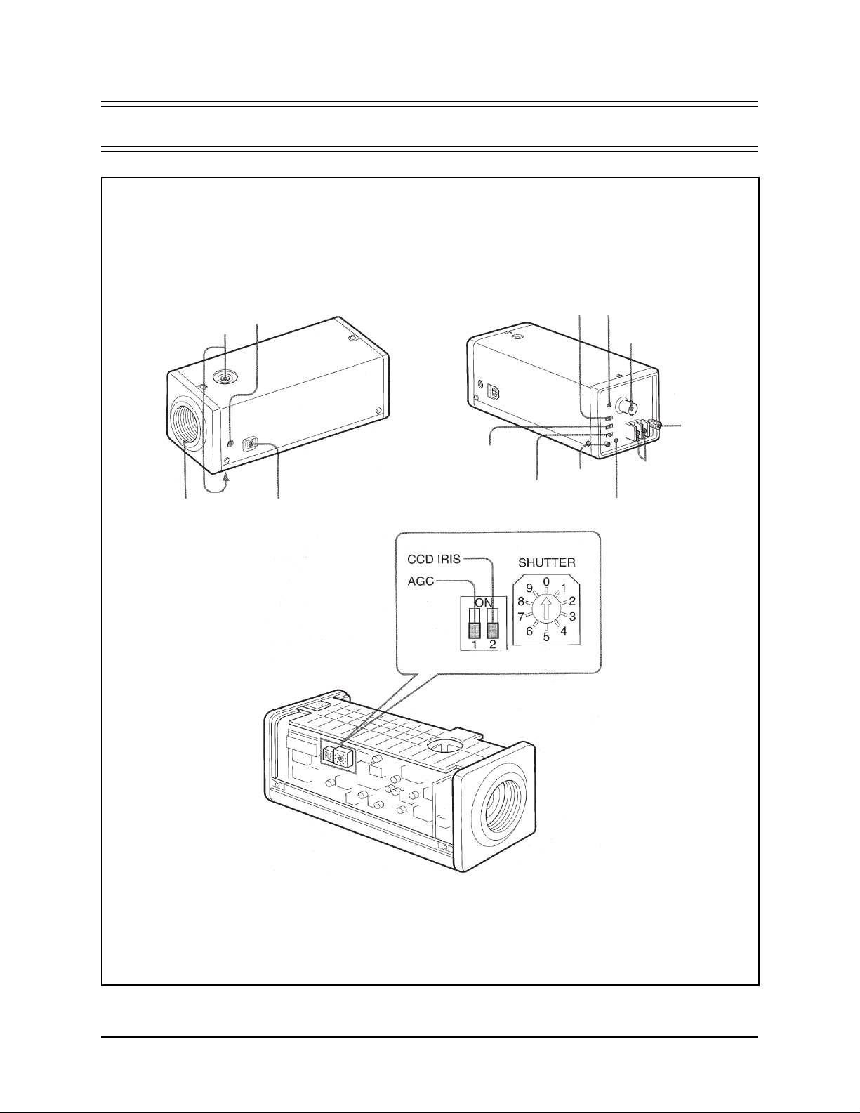
3.0 LOCATION OF PARTS AND CONTROLS
MOUNTING
LENS MOUNT
(C-MOUNT)
SCREW
HOLES
BACK FOCUS
ADJUSTMENT
SCREW
LENS CONNECTOR (4-PIN)
SYNC
SWITCH
WHITE
BALANCE
SWITCH
POWER
SWITCH
LOCK
BUTTON
V-PHASE BUTTON
POWER
INDICATOR
VIDEO OUT
CONNECTOR
POWER
TERMINALS
(24 VA C)
GROUND
TERMINAL
Figure 1. Location of Parts and Controls
4 Pelco Manual C1917M (12/97)
Page 9

4.0 INSTALLATION
1. Remove the six (6) Phillips screws that hold the upper cover to the camera
body and remove the cover (refer to Figure 2).
2. Set the internal switches according to the conditions in which the camera will
be used (refer to Figures 2 and 3).
Switch Settings
AGC ON
OFF (gain: 0 dB)
CCD IRIS* ON
SHUTTER (only effective when CCD IRIS is off)
* When using a manual iris lens, the CCD IRIS function automatically adjusts
the shutter speed to maintain a suitable exposure level. Turn this switch off
when using an auto-iris lens.
The CCD IRIS function used in the internal synchronization mode (SYNC switch
set to INT) may cause unstable color reproduction (slow color changes) to an
object shot under fluorescent lighting or unstable (flickering) lighting conditions. If the color changes are too extreme for the picture to be used, turn the
CCD IRIS function off and use an auto-iris lens.
OFF
0: 1/60 s 4: 1/1000 s
1: 1/100 s 5: 1/2000 s
2: 1/250 s 6: 1/4000 s
3: 1/500 s 7: 1/10000 s
Figure 2. Removal of Camera Cover Figure 3. Internal Switch Settings
Pelco Manual C1917M (12/97) 5
Page 10

3. Replace the upper cover on the camera body.
4. Make sure that you have the right type of lens to install on the camera.
The lens must be a C-mount type, and the screw thread must not project more
than 9 mm (3/8-inch) from the lens mounting surface (refer to Figure 4).
This camera uses a 1/2-inch CCD, so the lens should be for use with this size
of CCD. If you use a lens for a 2/3-inch CCD, the angle of view will be different.
5. If you have an auto-iris lens, replace the plug on the lens cable with the plug
that is supplied (refer to Figure 5).
a. Solder the lens cable wires to the pins on the plug supplied; apply heat
after putting heat shrink sleeving on the wires. The pin assignments are
as follows.
Pin Signal
1 Power Supply (+9V DC, 50 mA)
2 Unused
3 Video signal output (for auto-iris control; 0.7 Vp-p, 40 k ohms, no
synchronizing signal)
4 Ground
Refer to the operation manual for the lens to determine the cable color
coding.
b. Put the cover on the plug.
Figure 4. Lens Mount Figure 5. Auto-Iris Lens Plug Assembly
6 Pelco Manual C1917M (12/97)
Page 11

6. When using an auto-iris lens, install it as follows. For a manual iris lens, omit
step c. Refer to Figure 6.
a. Unscrew the lens mount cap (1).
b. Screw in the lens (2).
c. Plug in the lens cable (3).
Figure 6. Lens Installation
7. Attach the camera to a mounting bracket with a mounting screw of the type
shown in Figure 7.
1/4" UNC (20 pitch)
d = 4.5 mm ±0.2 mm (ISO standard), or 0.197" (ASA standard).
Figure 7. Camera Mounting Screw
Pelco Manual C1917M (12/97) 7
Page 12

WARNING:
Be sure to connect
the power and ground leads to the
appropriate terminals. Wrong connection may cause malfunction
and/or damage to the video camera.
8. Connect power to the camera (refer to Figure 8).
This camera must always be operated with a 24 VAC class 2 power supply. In
the U.S.A., use a power supply that is UL Listed. In Canada, use a power
supply that is CSA Certified. Refer to Table A for wiring distances.
When using a transformer without a ground lead (two-lead type), connect the
output of the transformer to the 24 VAC 1 and 2 terminals of the camera.
Connect a ground lead to the GND terminal or an irregular voltage may be
generated in the AC power cord and may cause malfunction and/or damage
to the video camera.
When using a transformer with a ground lead (three-lead type), connect the
ground wire to the GND terminal and the other two wires to the 24 VAC 1 and
2 terminals of the camera.
If you wire more than one camera from the same transformer, connect one
side of the transformer to terminal 1 on all of the cameras, and connect the
other side of the transformer to terminal 2 on all of the cameras. If all of the
cameras are not connected the same, the cameras will be out of phase with
each other and may produce what appears to be vertical roll when switching
between cameras.
Figure 8. Power and Video Connections
8 Pelco Manual C1917M (12/97)
Page 13

Table A. 24 VAC Wiring Distances
The following are the recommended maximum distances for 24 VAC applications
and are calculated with a 10-percent voltage drop. (10-percent is generally the maximum allowable voltage drop for AC-powered devices.)
EXAMPLE:
An enclosure that requires 80 vA and is installed 35 feet
(10 m) from the transformer would
require a minimum wire gauge of
20 Awg.
NOTE:
Distances are calculated in
feet; values in parentheses are
meters.
Wire Gauge
20 18 16 14 12 10
10 283 451 716 1142 1811 2880
(86) (137) (218) (348) (551) (877)
20 141 225 358 571 905 1440
(42) (68) (109) (174) (275) (438)
30 94 150 238 380 603 960
(28) (45) (72) (115) (183) (292)
40 70 112 179 285 452 720
(21) (34) (54) (86) (137) (219)
50 56 90 143 228 362 576
(17) (27) (43) (69) (110) (175)
60 47 75 119 190 301 480
(14) (22) (36) (57) (91) (146)
70 40 64 102 163 258 411
(12) (19) (31) (49) (78) (125)
80 35 56 89 142 226 360
(10) (17) (27) (43) (68) (109)
90 31 50 79 126 201 320
(9) (15) (24) (38) (61) (97)
100 28 45 71 114 181 288
(8) (13) (21) (34) (55) (87)
110 25 41 65 103 164 261
(7) (12) (19) (31) (49) (79)
12023 3759 95150240
Total vA consumed
(7) (11) (17) (28) (45) (73)
13021 3455 87139221
(6) (10) (16) (26) (42) (67)
14020 3251 81129205
(6) (9) (15) (24) (39) (62)
15018 3047 76120192
(5) (9) (14) (23) (36) (58)
16017 2844 71113180
(5) (8) (13) (21) (34) (54)
17016 2642 67106169
(4) (7) (12) (20) (32) (51)
18015 2539 63100160
(4) (7) (11) (19) (30) (48)
19014 2337 60 95151
(4) (7) (11) (18) (28) (46)
20014 2235 57 90144
(4) (6) (10) (17) (27) (43)
Maximum distance from transformer to load
Pelco Manual C1917M (12/97) 9
Page 14

9. Connect a video cable to the VIDEO OUT connector on the camera (refer to
Figure 8). Refer to Table B for the type of video coaxial cable to use.
Table B. Video Coaxial Cable W iring Distances
Cable Type* Maximum Distance
RG59 750 ft (229 m)
RG 6 1,000 ft (305 m)
RG11 1,500 ft (457 m)
* Minimum cable requirements:
75 ohms impedance
All-copper center conductor
All-copper braided shield with 95% braid coverage
10. Set the SYNC (synchronization) switch.
INT (internal): for using the internal synchronizing signal.
L.L. (line lock): for locking the camera operation to the supply power frequency
as a synchronizing signal. The vertical drive frequency of the camera is locked
to the AC power frequency (60 Hz) instead of the internal clock of the camera
(59.94 Hz), avoiding picture roll during camera switching operations.
Proceed to Section 4.1, ADJUSTMENTS.
10 Pelco Manual C1917M (12/97)
Page 15

Turn on the camera power and make the following adjustments.
4.1.1 White Balance
After fitting the lens and making all the installation connections, use a monitor to
check the picture and set the white balance as described below (refer to Figure 9).
AWB (Automatic White Balance) mode:
This mode is appropriate when lighting conditions are more or less constant. Point
the camera at a white object, such as a white wall or piece of white paper, so that
the monitor screen is as far as possible all white, then press the LOCK button. This
will calculate the current white balance setting and store it indefinitely in memory.
Thus there is no need to readjust the white balance after the power is turned off and
on again.
ATW (Automatic Tracing White Balance) mode:
In this mode the camera continuously adjusts the white balance according to the
changing lighting conditions.
4.1 ADJUSTMENTS
Figure 9. White Balance Setting
Pelco Manual C1917M (12/97) 11
Page 16

4.1.2 Vertical Phase
Use the V PHASE (vertical phase) button to compensate for vertical phase discrepancies that may occur when two or more cameras are used when the SYNC switch
is set to L.L. Use the tip of a ballpoint pen or the like to press the button. Each time
it is pressed, the line lock position shifts by 60°.
Vertical phase adjustment is not vertical roll adjustment. Vertical phase problems
arise when:
1. Switching rapidly between widely separated cameras with manual or sequential switchers.
2. Switching between cameras not operating off the same phase of the AC line.
3. Transformers are wired backward (refer to step 8 in Section 4.0, INSTALLATION).
When the vertical phase is out of adjustment, switching between two cameras
may produce what appears to be vertical roll on the monitor. Turning the vertical phase adjustment on the camera, while switching as rapidly as possible
between the two camera views, will synchronize the cameras to the same
phase of the AC line so that there is no vertical roll or flip when switching
between cameras.
4.1.3 Back Focus
The camera is shipped with the back focus adjusted to suit almost all lenses. If
necessary, turn the BACK FOCUS adjusting screw with a screwdriver to adjust the
focal plane. It has a self-locking mechanism, so once adjusted the focus will not
drift.
Fixed Lens Models (Indoor Method)
1. With the camera operating, view an object at least 75 feet away.
2. Set the lens focus ring to infinity.
3. Set the lens iris to its widest usable opening.*
4. Adjust the back focus to bring the object being viewed into the sharpest focus.
Fixed Lens Models (Outdoor Method)
1. With the camera operating, view an object at least 200 feet away.
2. Set the lens focus ring to infinity.
3. Use a neutral density filter in front of the lens to insure that the iris is fully
open.*
4. Adjust the back focus to bring the object being viewed into the sharpest focus
(the filter must be in place).
*The lens aperture must be wide open for all back focus adjustment procedures.
This can be done in subdued lighting or with filters.
12 Pelco Manual C1917M (12/97)
Page 17

Zoom Lens Models
1. With the camera operating, view an object at least 75 feet away.
2. Make sure the lens iris is wide open.* If outdoors use a neutral density filter in
front of the lens to insure that the iris is fully open.
3. Set the lens focus to infinity.
4. Adjust the lens zoom to extreme WIDE angle.
5. Adjust the back focus to bring the object being viewed into the sharpest focus
(the filter must be in place if the adjustment is being made outdoors).
6. Move the lens to extreme TELEPHOTO.
7. Adjust the lens focus (by the controller) for best picture.
*The lens aperture must be wide open for all back focus adjustment procedures.
This can be done in subdued lighting or with filters.
Pelco Manual C1917M (12/97) 13
Page 18

5.0 OPERATION
Avoid aiming the camera at a very bright object (such as light fixtures) for an extended period.
14 Pelco Manual C1917M (12/97)
Page 19

6.0 TROUBLESHOOTING
The following conditions that may be observed when using a CCD camera are not
associated with any fault of the camera.
Vertical Smear
This phenomenon occurs when shooting a very bright object.
Patterned Noise and Blemish
This is a fixed pattern which may appear over the entire monitor screen when the
camera is operated at a high temperature.
Jagged Picture
When shooting stripes, straight lines, or similar patterns, the image on the screen
may appear jagged.
Camera Does Not Operate
The only service you can perform on the camera is to inspect and change the
fuse. To check the fuse, remove the upper cover. If the fuse is bad, replace it with
the same type of fuse rated at 125 V AC, 500 mA. If the fuse blows after replacing
it, or if there are other problems with the camera, return the camera to Pelco for
servicing.
Pelco Manual C1917M (12/97) 15
Page 20

7.0 MAINTENANCE
Be careful not to spill water or other liquids on the unit, or to get combustible or
metallic material inside the body. Foreign material inside the camera could cause it
to fail or be a cause of fire or electric shock.
Avoid operating or storing the unit in the following locations:
Extremely hot or cold places (operating temperature 14° F to 122° F ; -10° C
to 50° C)
Damp or dusty places
Where it is exposed to rain
Locations subject to strong vibration
Close to generators of powerful electromagnetic radiation such as radio or TV
transmitters
Remove dust or dirt on the surface of the lens or optical filter with a blower.
Clean the body with a dry soft cloth. If it is very dirty, use a cloth dampened with a
small quantity of neutral detergent, then wipe dry. Avoid the use of volatile solvents
such as thinners, alcohol, benzene, and insecticides. They may damage the surface finish, or impair the operation of the camera.
16 Pelco Manual C1917M (12/97)
Page 21

8.0 SPECIFICATIONS
Pickup Device: 1/2-inch interline transfer type CCD
Effective Picture
Elements: 768 (H) x 494 (V)
Sensing Area: 6.3 x 4.7 mm (1/4 x 3/16 inch)
Lens Mount: C mount
Signal system: NTSC standard
Scanning System: 525 lines, 2:1 interlace, 30 frames per second
Synchronization: Internal or line-lock
Horizontal
Resolution: 470 TV lines
Minimum
Illumination: 2.5 lux at f/1.2 (AGC on)
Video Output: 1.0 Vp-p, 75 ohms, sync negative
Video
Signal-to-noise
Ratio: 48 dB minimum (AGC on)
Electronic Shutter: 8 settings: 1/60 s, 1/100* s, 1/250 s, 1/500 s, 1/1000 s, 1/2000 s,
White Balance: AWB (Automatic White Balance) and ATW (Automatic Tracing
AGC: Switchable on and off
Input and
Output Connectors: 24 VAC: two terminals
Power
Requirements: 24 VAC ±10%, 60 Hz
Power
consumption: 4.9 W
Operating
Temperature: 14° F to 122° F (-10° C to 50° C)
Storage
Temperature: -40° F to 140° F (-40° C to 60° C)
Relative Humidity
(operating): 20% to 80%
Relative Humidity
(storage): 20% to 95%
1/4000 s, 1/10000 s
White Balance), switchable
GND
VIDEO OUT: BNC type
LENS: 4-pin connector
Shock Resistance: 70 G (686.5 m/s2)
* Flickerless mode
Pelco Manual C1917M (12/97) 17
Page 22

Dimensions: See Figure 10
Weight: 660 g approx. (1 lb 7 oz)
Fuse: 125 VAC, 500 mA
(Design and product specifications subject to change without notice.)
6.50 (16.51)
6.12 (15.54)
1.59 (4.04)
2.52 (6.40)
2.23
(5.66)
BACK FOCUS
LENS
Hi Resolution
COLOR VIDEO CAMERA
NOTE: VALUES IN PARENTHESES ARE CENTIMETERS; ALL OTHERS ARE INCHES
Figure 10. CC4700-2 Dimension Drawing
18 Pelco Manual C1917M (12/97)
Page 23

NOTES
Pelco Manual C1917M (12/97) 19
Page 24

9.0 WARRANTY AND RETURN INFORMATION
WARRANTY
Pelco will repair or replace, without charge, any merchandise proved defective in material or
workmanship for a period of one year after the date of shipment.
Exceptions to this warranty are as noted below:
Pelco, the Pelco logo, Camclosure, Esprit,
Genex, Legacy, and Spectra are registered
trademarks of Pelco.
Endura and ExSite are trademarks of Pelco.
© Copyright 1997, Pelco. All rights reserved.
• Five years on FT/FR8000 Series fiber optic products.
• Three years on Genex
• Three years on Camclosure
2X, CC3751H-2, CC3651H-2X, MC3651H-2, and MC3651H-2X camera models, which have
a five-year warranty.
• Two years on standard motorized or fixed focal length lenses.
• Two years on Legacy
dome products.
• Two years on Spectra
continuous motion applications.
• Two years on Esprit
• Eighteen months on DX Series digital video recorders, NVR300 Series network video
recorders, and Endura
• One year (except video heads) on video cassette recorders (VCRs). Video heads will be
covered for a period of six months.
• Six months on all pan and tilts, scanners or preset lenses used in continuous motion
applications (that is, preset scan, tour and auto scan modes).
Pelco will warrant all replacement parts and repairs for 90 days from the date of Pelco shipment.
All goods requiring warranty repair shall be sent freight prepaid to Pelco, Clovis, California.
Repairs made necessary by reason of misuse, alteration, normal wear, or accident are not
covered under this warranty.
Pelco assumes no risk and shall be subject to no liability for damages or loss resulting from the
specific use or application made of the Products. Pelco’s liability for any claim, whether based
on breach of contract, negligence, infringement of any rights of any party or product liability,
relating to the Products shall not exceed the price paid by the Dealer to Pelco for such Products.
In no event will Pelco be liable for any special, incidental or consequential damages (including
loss of use, loss of profit and claims of third parties) however caused, whether by the negligence
of Pelco or otherwise.
The above warranty provides the Dealer with specific legal rights. The Dealer may also have
additional rights, which are subject to variation from state to state.
If a warranty repair is required, the Dealer must contact Pelco at (800) 289-9100 or (559) 2921981 to obtain a Repair Authorization number (RA), and provide the following information:
1. Model and serial number
2. Date of shipment, P.O. number, Sales Order number, or Pelco invoice number
3. Details of the defect or problem
If there is a dispute regarding the warranty of a product which does not fall under the warranty
conditions stated above, please include a written explanation with the product when returned.
Method of return shipment shall be the same or equal to the method by which the item was
received by Pelco.
RETURNS
In order to expedite parts returned to the factory for repair or credit, please call the factory at (800)
289-9100 or (559) 292-1981 to obtain an authorization number (CA number if returned for credit,
and RA number if returned for repair).
All merchandise returned for credit may be subject to a 20% restocking and refurbishing charge.
Goods returned for repair or credit should be clearly identified with the assigned CA or RA number
and freight should be prepaid. Ship to the appropriate address below.
If you are located within the continental U.S., Alaska, Hawaii or Puerto Rico, send goods to:
If you are located outside the continental U.S., Alaska, Hawaii or Puerto Rico and are instructed
to return goods to the USA, you may do one of the following:
If the goods are to be sent by a COURIER SERVICE, send the goods to:
If the goods are to be sent by a FREIGHT FORWARDER, send the goods to:
Service Department
Pelco
3500 Pelco Way
Clovis, CA 93612-5699
Pelco
3500 Pelco Way
Clovis, CA 93612-5699 USA
Pelco c/o Expeditors
473 Eccles Avenue
South San Francisco, CA 94080 USA
Phone: 650-737-1700
Fax: 650-737-0933
®
Series products (multiplexers, server, and keyboard).
®
and fixed camera models, except the CC3701H-2, CC3701H-
®
, CM6700/CM6800/CM9700 Series matrix, and DF5/DF8 Series fixed
®
, Esprit®, ExSite™, and PS20 scanners, including when used in
®
and WW5700 Series window wiper (excluding wiper blades).
™
Series distributed network-based video products.
20 Pelco Manual C1917M (12/97)
 Loading...