


Dual DeltaFex® Digital Effects Processor Owner's Manual
For information on other great Peavey products, go to your local Peavey dealer or visit us online at www.peavey.com
Intended to alert the user to the presence of uninsulated “dangerous voltage” within the product’s enclosure that may be of sufficient magnitude to constitute a risk of electric shock to persons.
Intended to alert the user of the presence of important operating and maintenance (servicing) instructions in the literature accompanying the product.
CAUTION: Risk of electrical shock — DO NOT OPEN!
CAUTION: To reduce the risk of electric shock, do not remove cover. No user serviceable parts inside. Refer servicing to qualified service personnel.
WARNING: To prevent electrical shock or fire hazard, this apparatus should not be exposed to rain or moisture‚ and objects filled with liquids‚ such as vases‚ should not be placed on this apparatus. Before using this apparatus‚ read the operating guide for further warnings.
Este símbolo tiene el propósito, de alertar al usuario de la presencia de “(voltaje) peligroso” sin aislamiento dentro de la caja del producto y que puede tener una magnitud suficiente como para constituir riesgo de descarga eléctrica.
Este símbolo tiene el propósito de alertar al usario de la presencia de instruccones importantes sobre la operación y mantenimiento en la información que viene con el producto.
PRECAUCION: Riesgo de descarga eléctrica ¡NO ABRIR!
PRECAUCION: Para disminuír el riesgo de descarga eléctrica, no abra la cubierta. No hay piezas útiles dentro. Deje todo mantenimiento en manos del personal técnico cualificado.
ADVERTENCIA: Para prevenir choque electrico o riesgo de incendios, este aparato no se debe exponer a la lluvia o a la humedad. Los objetos llenos de liquidos, como los floreros, no se deben colocar encima de este aparato. Antes de usar este aparato, lea la guia de funcionamiento para otras advertencias.
Ce symbole est utilisé dans ce manuel pour indiquer à l’utilisateur la présence d’une tension dangereuse pouvant être d’amplitude suffisante pour constituer un risque de choc électrique.
Ce symbole est utilisé dans ce manuel pour indiquer à l’utilisateur qu’il ou qu’elle trouvera d’importantes instructions concernant l’utilisation et l’entretien de l’appareil dans le paragraphe signalé.
ATTENTION: Risques de choc électrique — NE PAS OUVRIR!
ATTENTION: Afin de réduire le risque de choc électrique, ne pas enlever le couvercle. Il ne se trouve à l’intérieur aucune pièce pouvant être reparée par l’utilisateur. Confiez I’entretien et la réparation de l’appareil à un réparateur Peavey agréé.
AVIS: Dans le but de reduire les risques d’incendie ou de decharge electrique, cet appareil ne doit pas etre expose a la pluie ou a l’humidite et aucun objet rempli de liquide, tel qu’un vase, ne doit etre pose sur celui-ci. Avant d’utiliser de cet appareil, lisez attentivement le guide fonctionnant pour avertissements supplémentaires.
Dieses Symbol soll den Anwender vor unisolierten gefährlichen Spannungen innerhalb des Gehäuses warnen, die von Ausreichender Stärke sind, um einen elektrischen Schlag verursachen zu können.
Dieses Symbol soll den Benutzer auf wichtige Instruktionen in der Bedienungsanleitung aufmerksam machen, die Handhabung und Wartung des Produkts betreffen.
VORSICHT: Risiko — Elektrischer Schlag! Nicht öffnen!
VORSICHT: Um das Risiko eines elektrischen Schlages zu vermeiden, nicht die Abdeckung enfernen. Es befinden sich keine Teile darin, die vom Anwender repariert werden könnten. Reparaturen nur von qualifiziertem Fachpersonal durchführen lassen.
WARNUNG: Um elektrischen Schlag oder Brandgefahr zu verhindern, sollte dieser Apparat nicht Regen oder Feuchtigkeit ausgesetzt werden und Gegenstände mit Flüssigkeiten gefuellt, wie Vasen, nicht auf diesen Apparat gesetzt werden. Bevor dieser Apparat verwendet wird, lesen Sie bitte den Funktionsführer für weitere Warnungen.
2

IMPORTANT SAFETY INSTRUCTIONS
WARNING: When using electrical products, basic cautions should always be followed, including the following:
1.Read these instructions.
2.Keep these instructions.
3.Heed all warnings.
4.Follow all instructions.
5.Do not use this apparatus near water.
6.Clean only with a dry cloth.
7.Do not block any of the ventilation openings. Install in accordance with manufacturer’s instructions.
8.Do not install near any heat sources such as radiators, heat registers, stoves or other apparatus (including amplifiers) that produce heat.
9.Do not defeat the safety purpose of the polarized or grounding-type plug. A polarized plug has two blades with one wider than the other. A grounding type plug has two blades and a third grounding plug. The wide blade or third prong is provided for your safety. If the provided plug does not fit into your outlet, consult an electrician for replacement of the obsolete outlet.
10.Protect the power cord from being walked on or pinched, particularly at plugs, convenience receptacles, and the point they exit from the apparatus.
11.Only use attachments/accessories provided by the manufacturer.
12.Use only with a cart, stand, tripod, bracket, or table specified by the manufacturer, or sold with the apparatus. When a
cart is used, use caution when moving the cart/apparatus combination to avoid injury from tip-over.
13.Unplug this apparatus during lightning storms or when unused for long periods of time.
14.Refer all servicing to qualified service personnel. Servicing is required when the apparatus has been damaged in any way, such as power-supply cord or plug is damaged, liquid has been spilled or objects have fallen into the apparatus, the apparatus has been exposed to rain or moisture, does not operate normally, or has been dropped.
15.Never break off the ground pin. Write for our free booklet “Shock Hazard and Grounding.” Connect only to a power supply of the type marked on the unit adjacent to the power supply cord.
16.If this product is to be mounted in an equipment rack, rear support should be provided.
17.Note for UK only: If the colors of the wires in the mains lead of this unit do not correspond with the terminals in your plug‚ proceed as follows:
a)The wire that is colored green and yellow must be connected to the terminal that is marked by the letter E‚ the earth symbol‚ colored green or colored green and yellow.
b)The wire that is colored blue must be connected to the terminal that is marked with the letter N or the color black.
c)The wire that is colored brown must be connected to the terminal that is marked with the letter L or the color red.
18.This electrical apparatus should not be exposed to dripping or splashing and care should be taken not to place objects containing liquids, such as vases, upon the apparatus.
19.Exposure to extremely high noise levels may cause a permanent hearing loss. Individuals vary considerably in susceptibility to noise-induced hearing loss, but nearly everyone will lose some hearing if exposed to sufficiently intense noise for a sufficient time. The U.S. Government’s Occupational Safety and Health Administration (OSHA) has specified the following permissible noise level exposures:
Duration Per Day In Hours |
Sound Level dBA, Slow Response |
8 |
90 |
6 |
92 |
4 |
95 |
3 |
97 |
2 |
100 |
1 1⁄2 |
102 |
1 |
105 |
1⁄2 |
110 |
1⁄4 or less |
115 |
According to OSHA, any exposure in excess of the above permissible limits could result in some hearing loss. Ear plugs or protectors to the ear canals or over the ears must be worn when operating this amplification system in order to prevent a permanent hearing loss, if exposure is in excess of the limits as set forth above. To ensure against potentially dangerous exposure to high sound pressure levels, it is recommended that all persons exposed to equipment capable of producing high sound pressure levels such as this amplification system be protected by hearing protectors while this unit is in operation.
SAVE THESE INSTRUCTIONS!
3

WICHTIGE SICHERHEITSHINWEISE
ACHTUNG: Beim Einsatz von Elektrogeräten müssen u.a. grundlegende Vorsichtsmaßnahmen befolgt werden:
1.Lesen Sie sich diese Anweisungen durch.
2.Bewahren Sie diese Anweisungen auf.
3.Beachten Sie alle Warnungen.
4.Befolgen Sie alle Anweisungen.
5.Setzen Sie dieses Gerät nicht in der Nähe von Wasser ein.
6.Reinigen Sie es nur mit einem trockenen Tuch.
7.Blockieren Sie keine der Lüftungsöffnungen. Führen Sie die Installation gemäß den Anweisungen des Herstellers durch.
8.Installieren Sie das Gerät nicht neben Wärmequellen wie Heizungen, Heizgeräten, Öfen oder anderen Geräten (auch Verstärkern), die Wärme erzeugen.
9.Beeinträchtigen Sie nicht die Sicherheitswirkung des gepolten Steckers bzw. des Erdungssteckers. Ein gepolter Stecker weist zwei Stifte auf, von denen einer breiter ist als der andere. Ein Erdungsstecker weist zwei Stifte und einen dritten Erdungsstift auf. Der breite Stift bzw. der dritte Stift dient Ihrer Sicherheit. Sollte der beiliegende Stecker nicht in Ihre Steckdose passen, wenden Sie sich bitte an einen Elektriker, um die ungeeignete Steckdose austauschen zu lassen.
10.Schützen Sie das Netzkabel, sodass niemand darauf tritt oder es geknickt wird, insbesondere an Steckern oder Buchsen und ihren Austrittsstellen aus dem Gerät.
11.Verwenden Sie nur die vom Hersteller erhältlichen Zubehörgeräte oder Zubehörteile.
12.Verwenden Sie nur einen Wagen, Stativ, Dreifuß, Träger oder Tisch, der den Angaben des Herstellers entspricht oder zusammen
mit dem Gerät verkauft wurde. Wird ein Wagen verwendet, bewegen Sie den Wagen mit dem darauf befindlichen Gerät besonders vorsichtig, damit er nicht umkippt und möglicherweise jemand verletzt wird.
13.Trennen Sie das Gerät während eines Gewitters oder während längerer Zeiträume, in denen es nicht benutzt wird, von der Stromversorgung.
14.Lassen Sie sämtliche Wartungsarbeiten von qualifizierten Kundendiensttechnikern durchführen. Eine Wartung ist erforderlich, wenn das Gerät in irgendeiner Art beschädigt wurde, etwa wenn das Netzkabel oder der Netzstecker beschädigt wurden, Flüssigkeit oder Gegenstände in das Gerät gelangt sind, das Gerät Regen oder Feuchtigkeit ausgesetzt wurde, nicht normal arbeitet oder heruntergefallen ist.
15.Der Erdungsstift darf nie entfernt werden. Auf Wunsch senden wir Ihnen gerne unsere kostenlose Broschüre „Shock Hazard and Grounding“ (Gefahr durch elektrischen Schlag und Erdung) zu. Schließen Sie nur an die Stromversorgung der Art an, die am Gerät neben dem Netzkabel angegeben ist.
16.Wenn dieses Produkt in ein Geräte-Rack eingebaut werden soll, muss eine Versorgung über die Rückseite eingerichtet werden.
17.Hinweis – Nur für Großbritannien: Sollte die Farbe der Drähte in der Netzleitung dieses Geräts nicht mit den Klemmen in Ihrem Stecker übereinstimmen, gehen Sie folgendermaßen vor:
a)Der grün-gelbe Draht muss an die mit E (Symbol für Erde) markierte bzw. grüne oder grün-gelbe Klemme angeschlossen werden.
b)Der blaue Draht muss an die mit N markierte bzw. schwarze Klemme angeschlossen werden.
c)Der braune Draht muss an die mit L markierte bzw. rote Klemme angeschlossen werden.
18.Dieses Gerät darf nicht ungeschützt Wassertropfen und Wasserspritzern ausgesetzt werden und es muss darauf geachtet werden, dass keine mit Flüssigkeiten gefüllte Gegenstände, wie z. B. Blumenvasen, auf dem Gerät abgestellt werden.
19.Belastung durch extrem hohe Lärmpegel kann zu dauerhaftem Gehörverlust führen. Die Anfälligkeit für durch Lärm bedingten Gehörverlust ist von Mensch zu Mensch verschieden, das Gehör wird jedoch bei jedem in gewissem Maße geschädigt, der über einen bestimmten Zeitraum ausreichend starkem Lärm ausgesetzt ist. Die US-Arbeitsschutzbehörde (Occupational and Health Administration, OSHA) hat die folgenden zulässigen Pegel für Lärmbelastung festgelegt:
Dauer pro Tag in Stunden |
Geräuschpegel dBA, langsame Reaktion |
8 |
90 |
6 |
92 |
4 |
95 |
3 |
97 |
2 |
100 |
1 1⁄2 |
102 |
1 |
105 |
1⁄2 |
110 |
1⁄4 oder weniger |
115 |
Laut OSHA kann jede Belastung über den obenstehenden zulässigen Grenzwerten zu einem gewissen Gehörverlust führen. Sollte die Belastung die obenstehenden Grenzwerte übersteigen, müssen beim Betrieb dieses Verstärkungssystems Ohrenstopfen oder
Schutzvorrichtungen im Gehörgang oder über den Ohren getragen werden, um einen dauerhaften Gehörverlust zu verhindern. Um sich vor einer möglicherweise gefährlichen Belastung durch hohe Schalldruckpegel zu schützen, wird allen Personen empfohlen, die mit Geräten arbeiten, die wie dieses Verstärkungssystem hohe Schalldruckpegel erzeugen können, beim Betrieb dieses Geräts einen Gehörschutz zu tragen.
BEWAHREN SIE DIESE SICHERHEITSHINWEISE AUF!
4

INSTRUCTIONS IMPORTANTES DE SECURITE
ATTENTION: L’utilisation de tout appareil électrique doit être soumise aux precautions d’usage incluant:
1.Lire ces instructions.
2.Gardez ce manuel pour de futures références.
3.Prétez attention aux messages de précautions de ce manuel.
4.Suivez ces instructions.
5.N’utilisez pas cette unité proche de plans d’eau.
6.N’utilisez qu’un tissu sec pour le nettoyage de votre unité.
7.N’obstruez pas les systèmes de refroidissement de votre unité et installez votre unité en fonction des instructions de ce manuel.
8.Ne positionnez pas votre unité à proximité de toute source de chaleur.
9.Connectez toujours votre unité sur une alimentation munie de prise de terre utilisant le cordon d’alimentation fourni.
10.Protégez les connecteurs de votre unité et positionnez les cablages pour éviter toutes déconnexions accidentelles.
11.N’utilisez que des fixations approuvées par le fabriquant.
12.Lors de l’utilsation sur pied ou pole de support, assurez dans le cas de déplacement de l’ensemble enceinte/
support de prévenir tout basculement intempestif de celui-ci.
13.Il est conseillé de déconnecter du secteur votre unité en cas d’orage ou de durée prolongée sans utilisation.
14.Seul un technicien agréé par le fabriquant est à même de réparer/contrôler votre unité. Celle-ci doit être contrôlée si elle a subit des dommages de manipulation, d’utilisation ou de stockage (humidité,…).
15.Ne déconnectez jamais la prise de terre de votre unité.
16.Si votre unité est destinée a etre montée en rack, des supports arriere doivent etre utilises.
17.Note pour les Royaumes-Unis: Si les couleurs de connecteurs du cable d’alimentation ne correspond pas au guide de la prise secteur, procédez comme suit:
a)Le connecteur vert et jaune doit être connectrer au terminal noté E, indiquant la prise de terre ou correspondant aux couleurs verte ou verte et jaune du guide.
b)Le connecteur Bleu doit être connectrer au terminal noté N, correspondnat à la couleur noire du guide.
c)Le connecteur marron doit être connectrer au terminal noté L, correspondant à la couleur rouge du guide.
18.Cet équipement électrique ne doit en aucun cas être en contact avec un quelconque liquide et aucun objet contenant un liquide, vase ou autre ne devrait être posé sur celui-ci.
19.Une exposition à de hauts niveaux sonores peut conduire à des dommages de l’écoute irréversibles. La susceptibilité au bruit varie considérablement d’un individu à l’autre, mais une large majorité de la population expériencera une perte de l’écoute après une exposition à une forte puissance sonore pour une durée prolongée. L’organisme de la santé américaine (OSHA) a produit le guide ci-dessous en rapport à la perte occasionnée:
Durée par Jour (heures) |
Niveau sonore moyen (dBA) |
8 |
90 |
6 |
92 |
4 |
95 |
3 |
97 |
2 |
100 |
1 1⁄2 |
102 |
1 |
105 |
1⁄2 |
110 |
1⁄4 ou inférieur |
115 |
D’après les études menées par le OSHA, toute exposition au delà des limites décrites ce-dessus entrainera des pertes de l’écoute chez la plupart des sujets. Le port de système de protection (casque, oreilette de filtrage,…) doit être observé lors de l’opération cette unité ou des dommages irréversibles peuvent être occasionnés. Le port de ces systèmes doit être observé par toutes personnes susceptibles d’être exposées à des conditions au delà des limites décrites ci-dessus.
GARDEZ CES INSTRUCTIONS!
5

INSTRUCCIONES IMPORTANTES PARA SU SEGURIDAD
CUIDADO: Cuando use productos electrónicos, debe tomar precauciones básicas, incluyendo las siguientes:
1.Lea estas instrucciones.
2.Guarde estas instrucciones.
3.Haga caso de todos los consejos.
4.Siga todas las instrucciones.
5.No usar este aparato cerca del agua.
6.Limpiar solamente con una tela seca.
7.No bloquear ninguna de las salidas de ventilación. Instalar de acuerdo a las instrucciones del fabricante.
8.No instalar cerca de ninguna fuente de calor como radiadores, estufas, hornos u otros aparatos (incluyendo amplificadores) que produzcan calor.
9.No retire la patilla protectora del enchufe polarizado o de tipo “a Tierra”. Un enchufe polarizado tiene dos puntas, una de ellas más ancha que la otra. Un enchufe de tipo “a Tierra” tiene dos puntas y una tercera “a Tierra”. La punta ancha (la tercera ) se proporciona para su seguridad. Si el enchufe proporcionado no encaja en su enchufe de red, consulte a un electricista para que reemplaze su enchufe obsoleto.
10.Proteja el cable de alimentación para que no sea pisado o pinchado, particularmente en los enchufes, huecos, y los puntos que salen del aparato.
11.Usar solamente añadidos/accesorios proporcionados por el fabricante.
12.Usar solamente un carro, pie, trípode, o soporte especificado por el fabricante, o vendido junto al aparato. Cuando se use
un carro, tenga cuidado al mover el conjunto carro/aparato para evitar que se dañe en un vuelco. No suspenda esta caja de ninguna manera.
13.Desenchufe este aparato durante tormentas o cuando no sea usado durante largos periodos de tiempo.
14.Para cualquier reparación, acuda a personal de servicio cualificado. Se requieren reparaciones cuando el aparato ha sido dañado de alguna manera, como cuando el cable de alimentación o el enchufe se han dañado, algún líquido ha sido derramado o algún objeto ha caído dentro del aparato, el aparato ha sido expuesto a la lluvia o la humedad, no funciona de manera normal, o ha sufrido una caída.
15.Nunca retire la patilla de Tierra.Escríbanos para obtener nuestro folleto gratuito “Shock Hazard and Grounding” (“Peligro de Electrocución y Toma a Tierra”). Conecte el aparato sólo a una fuente de alimentación del tipo marcado al lado del cable de alimentación.
16.Si este producto va a ser enracado con más equipo, use algún tipo de apoyo trasero.
17.Nota para el Reino Unido solamente: Si los colores de los cables en el enchufe principal de esta unidad no corresponden con los terminales en su enchufe‚ proceda de la siguiente manera:
a)El cable de color verde y azul debe ser conectado al terminal que está marcado con la letra E‚ el símbolo de Tierra (earth)‚ coloreado en verde o en verde y amarillo.
b)El cable coloreado en azul debe ser conectado al terminal que está marcado con la letra N o el color negro.
c)El cable coloreado en marrón debe ser conectado al terminal que está marcado con la letra L o el color rojo.
18.Este aparato eléctrico no debe ser sometido a ningún tipo de goteo o salpicadura y se debe tener cuidado para no poner objetos que contengan líquidos, como vasos, sobre el aparato.
19.La exposición a altos niveles de ruido puede causar una pérdida permanente en la audición. La susceptibilidad a la pérdida de audición provocada por el ruido varía según la persona, pero casi todo el mundo perderá algo de audición si se expone a un nivel de ruido suficientemante intenso durante un tiempo determinado. El Departamento para la Salud y para la Seguridad del Gobierno de los Estados Unidos (OSHA) ha especificado las siguientes exposiciones al ruido permisibles:
Duración por Día en Horas |
Nivel de Sonido dBA, Respuesta Lenta |
8 |
90 |
6 |
92 |
4 |
95 |
3 |
97 |
2 |
100 |
1 1⁄2 |
102 |
1 |
105 |
1⁄2 |
110 |
1⁄4 o menos |
115 |
De acuerdo al OSHA, cualquier exposición que exceda los límites arriba indicados puede producir algún tipo de pérdida en la audición. Protectores para los canales auditivos o tapones para los oídos deben ser usados cuando se opere con este sistema de sonido para prevenir una pérdida permanente en la audición, si la exposición excede los límites indicados más arriba. Para protegerse de una exposición a altos niveles de sonido potencialmente peligrosa, se recomienda que todas las personas expuestas a equipamiento capaz de producir altos niveles de presión sonora, tales como este sistema de amplificación, se encuentren protegidas por protectores auditivos mientras esta unidad esté operando.
GUARDE ESTAS INSTRUCCIONES!
6

ENGLISH
Dual DeltaFex®
Digital Effects Processor
Congratulations on your purchase of the Peavey Dual DeltaFex digital effects processor. You now have two programmable effect engines that can be used in four different configurations. Each engine can have one of 16 effect types, making the Dual DeltaFex useful for studios, P.A. systems or instrument processing.
CAUTION: Use only the 16.5 volt power supply provided with this product. If the original power supply must be replaced, consult your Peavey dealer or the factory for the correct replacement. Failure to use the correct power supply could result in fire, shock hazard, extensive circuit damage, decreased performance or non-operation.
FEATURES:
•Intuitive interface for preset recalling, editing, and storing
•200 presets (100 user/100 factory)
•24-bit converters and processing
•16 effect types, including reverbs, delays, modulations, distortion, karaoke, etc.
•Dual engines can be configured in series, parallel, dual mono or summed mono
•Four adjustments per effect (mix, param1, param2, level)
•Footswitch jack for effects defeat or rotary effect speed toggle
7
Front Panel
1 |
3 |
5 |
8 |
|
|
|
Preset |
|
|
|
|
EditA |
|
|
|
|
Edit B |
|
|
|
|
Defeat |
|
2 |
4 |
6 |
7 |
9 |
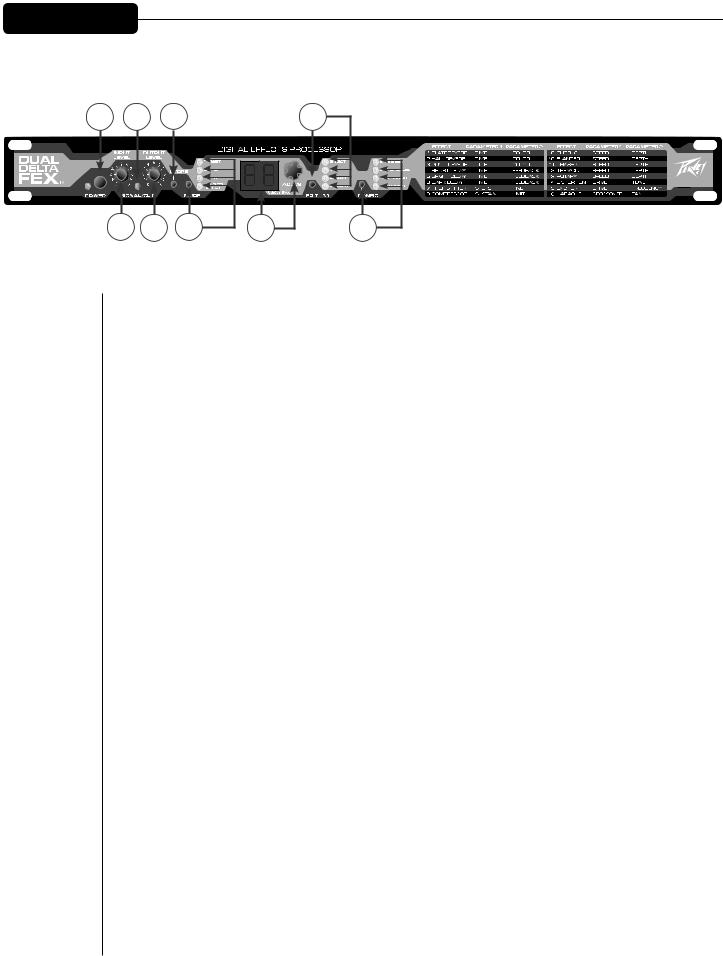
Power Button/LED (1)
Power (and LED) will be ON when switch is pushed in.
Input Level Control (2)
This knob attenuates or boosts the incoming signals (left and right). Set this so that the Signal/Clip LED turns red only on extreme peaks (or not at all).
Signal/Clip LED (3)
This will illuminated green when either of the input signals reaches 18 dB under clipping. It will switch to red when the level reaches 3 dB under clipping.
Output Level Control (4)
This knob controls the volume of the Left and Right outputs.
Store Button (5)
Press this to enter Preset Store mode, which allows you to store the current effect settings. A destination (00.-99.) can be selected, and a second “press” will store the data. (Pressing one of the other buttons instead of a second press of Store will exit Store mode.)
Mode Button/LEDs (6)
Pressing the Mode button will scroll through the top three LEDs (Preset mode, Edit A mode, Edit B mode). Holding for one second will enter Defeat mode, after which a simple press will exit Defeat mode.
Numerical Display/Data Wheel (7)
This is the main editing tool. The wheel allows editing of the parameter that is currently displayed, indicated by the discrete LEDs.
8

Front Panel
8
9 |
Edit Button/LEDs (8)
When in Edit A or Edit B mode, one of these LEDs (or all 4) will be illuminated, indicating which parameter is active for editing. All will be OFF when not in Edit mode. (When all are ON, you will be editing the output level for effect A or B.)
Configuration Button/LEDs (9)
These LEDs indicate the routing of two effect engines for the current preset – series, parallel, dual mono or sum mono. Use the button to step through the choices.
Series |
Dual Mono |
Parallel |
Sum Mono |
9
Rear Panel
1 |
2 |
3 |
4 |
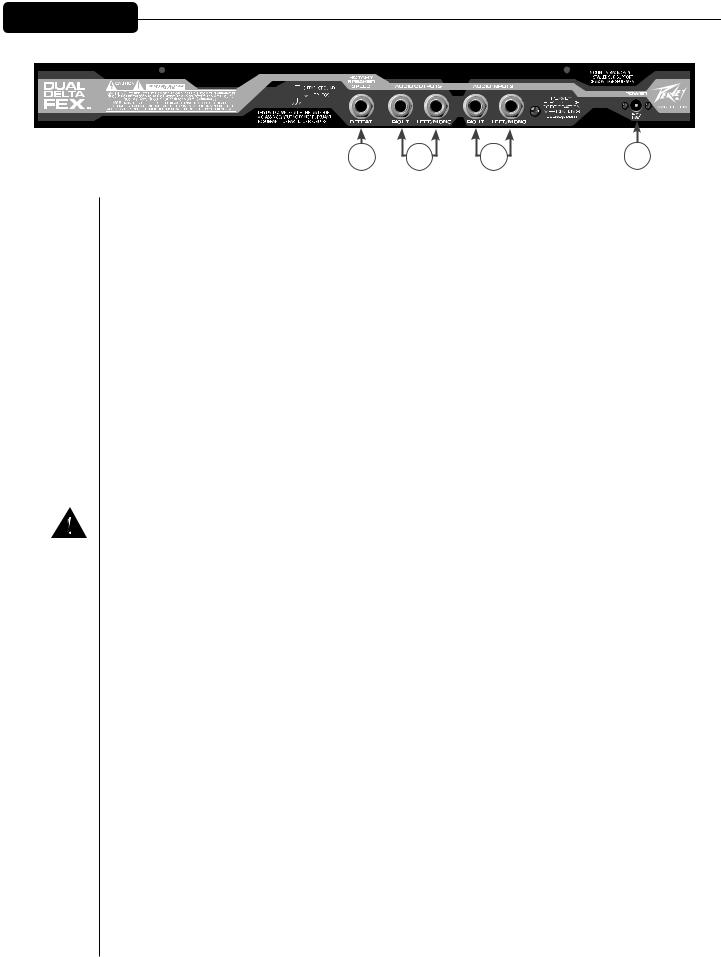
Rotary Speaker Speed/Defeat (1)
A momentary mono footswitch will allow effect defeat (bypass or mute) or rotary speed toggle. The polarity of the footswitch will be sensed at power-up to allow normally closed or normally open types without the need for a global parameter (so make sure the footswitch is connected before you power up).
Audio Outputs (2)
These are Right and Left/Mono line-level outputs. Without a connection to the Right jack, the Left jack will go into Mono mode. This will sum certain individual effects to mono, but it will not combine the outputs of a preset with the dual mono configuration.
Audio Inputs (3)
These are Right and Left/Mono line-level inputs. Without a connection to the Right jack, the Left jack will feed both sides.
Power (4)
Input for the 16 VAC, 1.1 amp power adapter.
NOTE: Use only Peavey part #70900660, which is a DV-1611A.
10
Operating Modes
Preset Recall Mode:
This is the default power-up mode. The Preset mode LED will be lit, the display will show the preset number and the data wheel will scroll through presets. Setting the mode Select button to “Preset” will put the unit into this mode at any time.
User Presets 00. - 99. will be shown first (with the decimal point lit), while fixed Factory Presets 00 - 99 will be shown next (without the decimal point lit).
Note: The unit can be re-initialized to factory default settings by holding STORE and MODE while powering up. This will copy the Factory presets to the User presets, and initialize any globals (like bypass vs. mute) to their default setting. You will see “in” on the display for a few seconds while the unit restores its default setting.
A preset consists of: the settings for both effect engines (effect type, mix, parameters 1 & 2, level) and the configuration (routing).
Store Mode:
Press the Store button to activate Store mode. The destination number will blink. If you are on a User preset, the destination will initially be the same as the preset. If you are on a Factory preset, the default destination will be the same preset number, but in the User bank. At this point, you have three options:
1.Press the Store button again to store into the current destination
2.Use the data wheel to choose a different location and then store
3.Press any other button to escape Store
Edit Mode:
Press the Select button to enter Edit A or Edit B mode. (Shortcut: pressing the EDIT button when in Preset mode will also enter Edit A mode.) One of the four LEDs to the right of the display will light. Once in Edit mode, the EDIT button will scroll down through five parameters (if the effect is not off): the four shown next to each LED, and all LEDs on, indicating output level for effect A or B. At each stop the display will show the value, and the data wheel can be used to edit it.
The parameter being edited/displayed belongs to either effect block A or B, indicated by the Mode LEDs.
The CONFIG button will step through the four configurations (see page 9), which control how the two effect engines are routed between the inputs and outputs for the current preset. Typically, you would set this before editing the parameters, since it can (and most likely will) affect the overall sound – mix ratios, depths, etc.
11

Operating Modes
Defeat Mode:
This mode can be entered via a momentary footswitch plugged into the DEFEAT jack on the rear of the unit. It can also be entered by holding the MODE switch for a full second.
Defeat mode can be exited by another press of the footswitch, or a normal press of the MODE switch.
The display will read “by” when in Bypass mode, and “mu” when in Mute mode. To change which mode is used, press the CONFIG button to alternate between them while in the Defeat mode. This is a global setting that the unit will remember when powered down.
The data wheel can still be used to select presets while defeated. You will see the preset number for a moment, after which the “by” or “mu” will return to the display. The preset will load inaudibly, so you will hear it almost immediately when exiting defeat mode. If you need to simply see the current preset number while defeated, press the EDIT button to see it for a couple seconds. The display will switch back to “by” or “mu” automatically.
Bypass Mode:
In this mode, the left input will be routed to the left output, and the right input will be routed to the right output (the input and output level knobs will still be active – it’s not a hard-wired bypass). Use this mode when the unit is in a serial-type loop, such as a guitar amp’s effects loop, between a mixer and amplifier, etc.
Mute Mode:
When in this mode, the outputs will be muted. Use this mode when the unit is in a parallel loop, like a mixer’s aux send, etc. If used in series with an instrument or as a channel insert, it will disable the channel.
Editing tip: Choose Bypass or Mute prior to editing presets. The default mix parameters will be 99 (100%) when in Mute mode – saving you time from having to set them there.
12

Edit Parameters
Effect:
This is the Effect Type currently assigned to the engine. The 16 types are listed on the front panel. You can also edit below 1 to turn the engine off (shown as “--”). You can assign any effect to either engine
– even the same effect in both.
Mix:
Most of the effects (all except Compressor and Tremolo) have a wet/dry mix (adjustable when the MIX LED is lit). 00 is fully dry, 50 is equal amounts of wet and dry and 99 is fully wet. When using in an aux send (P.A. or studio), set the mix to 99 to get an “all effect” feed to the aux return or channel. When used in the effects loop of a guitar amp, increasing mix levels from 0 to 50 will result in more audible effect while still hearing plenty of dry sound.
Level:
All of the effects have an output level that is adjustable when all four EDIT LEDs are lit. When used in parallel, this is useful to balance the outputs. In series configuration, engine B’s level is basically a programmable preset level, while engine A’s level can be used to control the level driving engine B.
Output level range is:
0-99 – 0-100% (20% audio taper) b1b6 – Boosted by 1 dB - 6 dB
Parameters 1 and 2:
These parameter names are listed on the front of the unit for convenience. The descriptions of these for each effect type are below.
1 Plate Reverb
2 Hall Reverb
3 Room Reverb
These effects simulate different reverberant spaces by creating dense layers of echoes. Plate is a popular electronic reverb type, while Hall and Room are designed to simulate those environments.
Parameter 1 (Time) – Reverberation time – from 1 second up to 10 seconds. There are half-second intervals near the bottom of the range, then 1 second intervals for the remainder.
Parameter 2 (Color) – This provides a way to make the reverb darker sounding via a high-cut filter. The settings (in kHz.) are 1, 2, 4, 8, and “br” for bright, which disables the filter.
13

Edit Parameters
4 Short Delay
5 Bright Delay
6 Dark Delay
The delay effects create discrete echoes. The short delay can be used to really fine tune a short duration, or extremely short and mixed with the dry for a fixed comb filter (flange) effect. The Bright Delay is a longer delay. The Dark Delay is also long, but cuts a significant amount of treble from the wet signal to simulate vintage tape and analog echo units.
Parameter 1 (Time) – Delay time from 1 to 99 ms. on the Short delay, and 10 ms. to 1.4 seconds on the Bright and Dark delays.
For the Bright and Dark (long) Delays, the display will read as follows:
10 – 90 |
– 10-90 ms. |
10. – 99. |
– 100-990 ms. (picture a “zero” on the right instead of the decimal) |
0.0. – 4.1. |
– 1.00-1.41 seconds (picture a “1” on the left instead of the decimals) |
Parameter 2 (Feedback) – The amount of delay output that is fed back to the delay input, resulting in more echoes being repeated. Range is 0% to 99%.
7 Pitch Shifter
This effect can be used totally wet (mix=99) to bring an instrument down a half step or more, or mixed with the dry sound to create a harmonized (using Steps) or detuned (using Fine) effect.
Parameter 1 (Steps) – This sets the coarse shift amount in semi-tones. Range is +/- 12.
Parameter 2 (Fine) – This will fine-tune the amount of pitch shift in between semitones. It’s useful when Steps is zero and mixed with the dry sound for a detuning effect. Range is +/-9.
Tip: When using two pitch shifters in parallel, it can be useful to mix them both fully wet with equal steps, but detune one slightly for some extra thickness.
8 Compressor
The Compressor effect reduces high signal levels and boosts small signal levels. The net result is a more consistent output volume and increased sustain.
Parameter 1 (Sustain) – This sets the maximum amount of gain that the compressor can use to amplify the signal up to the Limit level. It can be thought of as an intelligent drive control. Range is 0 to 6.
Parameter 2 (Limit) – This sets the maximum level that the compressor will allow on the output (even though transient peaks may exceed it for a short time since the attack time isn’t
instantaneous). Lower values will result in more apparent compression (which can be made up for with the output level). Range is 0% to 99%.
14

Edit Parameters
9 Chorus
10Flanger
11Phaser
12Tremolo
These are the standard modulation effects. The chorus modulates a left and right delay to create a detuned doubling. The flanger uses a shorter delay and feedback to create a modulated comb filter. The phaser uses modulated all-pass filters to create a different type of swept comb filter. The tremolo effect is the traditional amplitude-modulated effect.
Parameter 1 (Speed) – Rate of modulation, 0-99%.
Parameter 2 (Depth) – Intensity (width) of modulation, 0-99%.
13 Rotary
This effect simulates a two-way rotary speaker cabinet popular with organists (but is very useful on guitar and other signals). The signal is split into low and high frequencies and modulated separately and at slightly different speeds.
Parameter 1 (Speed) – Rate of modulation, 0-99%. Pressing the footswitch will allow you to toggle between two speeds, and you can set these low and high speeds however you want. (One of the speeds will be shown with the decimal point, and the other without.) The Rotary effect will ramp the speed between these values, just like a real rotating speaker.
If you want the footswitch to still act as a defeat, set either speed to “oF” for off, and the Dual DeltaFex® will enter Defeat (Bypass/Mute) mode instead of toggling the speed. (When editing Rotary, pressing the footswitch will always toggle the speed values to allow you to change the “oF” back to a real speed value.)
Parameter 2 (Depth) – Intensity (width) of modulation, 0-99%.
14 Distortion
The Distortion effect consists of a digital distortion followed by a tone section, then an optional speaker simulator for full-range systems (which removes a lot of the treble frequencies that a typical guitar cabinet does not reproduce). This effect does have a mix, which is something you don’t get with most distortion devices.
Tip: Experiment with running some dry sound along with the distortion to regain some note definition.
Parameter 1 (Drive) – The amount of gain, or distortion amount. Range: off, 0-10 (choose off to bypass the distortion and use the tone and speaker simulator by themselves).
Parameter 2 (Tone) – This cuts high end as you turn it down, like a tone knob on a distortion pedal. Range: 00 - 99 (non-cab simulated), then 00. - 99. (cab simulated).
15

Edit Parameters
15 Exciter
The Exciter effect adds harmonics as an enhancement to the dry signal. A popular use is to add a high-end “sheen” to vocals, acoustic guitars, etc.
Parameter 1 (Drive) – The amount of gain into the exciter, 0-99%. Higher gains produce more harmonics.
Parameter 2 (Frequency) – This controls the frequency of a low-cut filter preceding the exciter, allowing it to generate harmonics based on the higher frequencies.
16 Karaoke
This is a vocal removal effect that cancels any audio (above the crossover point) that is mixed down the center of the stereo field. Lead vocals are usually mixed this way, whereas instruments (and some background vocals) are usually panned away from center or stereo-mixed in other ways. Vocals mixed to center often have stereo effects added to them, so you will hear only the effects in many cases.
Note: Due to the nature of this effect, it will only work correctly under the following circumstances:
•Engine A in series mode (typical usage), or Engine B if Engine A is off
•Engine A or B in parallel mode with the other engine off (muted)
Parameter 1 (Crossover) – Frequencies lower than this point will not be canceled. Bass and kick drum are popular choices for mixing down the center, and the goal is for that low end to still be audible. Increase it for more bass, decrease for more cancellation on low-pitched vocals. Range is 100 Hz –190 Hz (display shows 0.0. – 9.0.).
Parameter 2 (Pan) – This will control the balance between the left/right mix (treble side, after the crossover). This could be used to get less cancellation when wanted, or get more cancellation in cases where the vocal may be slightly panned (or the source left and right signals are not the same exact level). Range is +/- 9 (default is 0).
Tip: What happens if you drive a mono signal into this effect? Interestingly enough, it acts as a drastic midrange scoop. Raising the Crossover point will increase the bass, and moving the Cancel Amt away from zero will increase the midrange. There is usually a substantial volume loss, but the output level can add 6 dB, and the other effect block can add more if used in series. Factory presets 71 and 81 use the Karaoke effect as a mid scoop for guitar.
16

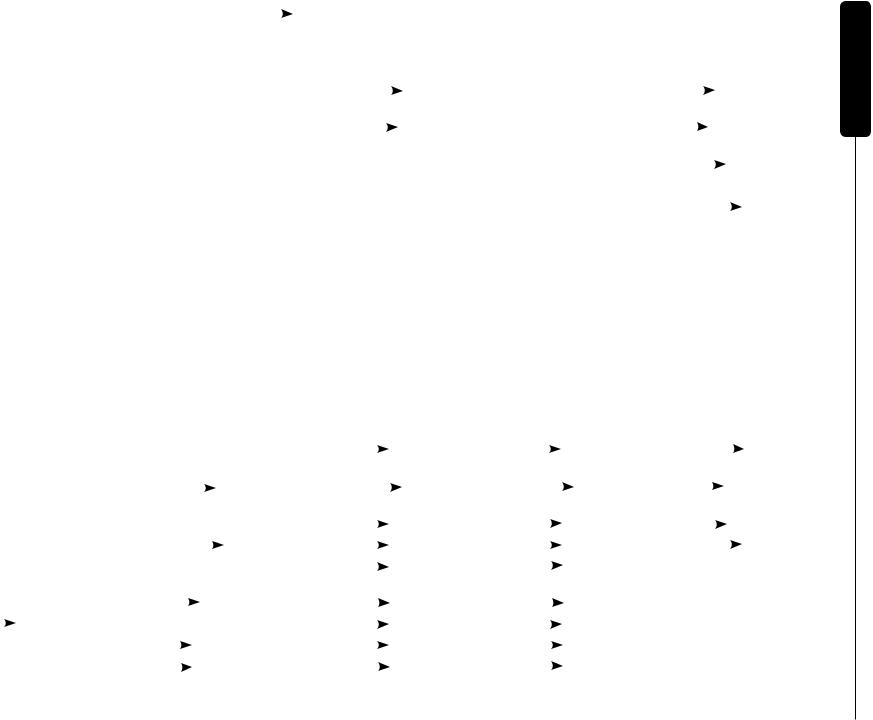
Factory Preset List
The following page shows the mapping for the 100 factory presets. These presets are always available as 00-99 (without the decimal point), and also reside in the user presets when the unit is initialized from the factory.
Presets 00 to 49 are designed for mixer aux sends and parallel effects loops (where the audio from the Dual DeltaFex® is adding to the already audible dry sound). Most mix settings will be full. These are typically used with the defeat mode set to Mute.
Presets 50 to 99 are designed for series-type applications (guitar amp serial effects loops, between guitar and amp, between CD player and mixer, etc.) Mix parameters are generally set for the dry sound to come through the unit with the effected sound added to it. These are typically used with the Defeat mode set to Bypass.
17
18
Configuration notation: |
|
|
series |
+ parallel |
| dual mono |
/ sum mono |
|
|
|
|
|
||||||||||
|
|
|
|
|
|
||||||||||||||||
00-49 – Parallel effects (mixer aux send, parallel effects loop, etc.) Use Mute mode for defeat footswitch. |
|
|
|
|
|
||||||||||||||||
|
|
|
|
|
|
|
|
|
|
|
|
|
|
|
|
|
|
|
|
|
|
Reverbs |
Delays |
Ambience |
|
|
|
|
|
Enhancement |
|
Combos |
|
|
|
|
|
||||||
|
|
|
|
(reverb/delay combos) |
|
|
|
|
|
|
|
|
|
|
|
|
|
||||
|
|
|
|
|
|
|
|
|
|
|
|
|
|
|
|
|
|
|
|
||
00 Normal Plate |
10 Short slap |
20 Bright Delay |
|
|
Hall |
30 Exciter |
|
40 Plate |
|
|
|
Chorus |
|||||||||
|
|
|
|
|
|
||||||||||||||||
|
|
|
|
|
|
|
|
|
|
|
|
(Chorused reverb tail) |
|||||||||
|
|
|
|
|
|
|
|
|
|
|
|
|
|
|
|
|
|
|
|
||
01 Long Plate |
11 Short slap with feedback |
21 Short Delay |
|
|
Plate |
31 Distortion |
|
41 Hall |
|
|
|
Phaser |
|||||||||
|
|
|
|
|
|
|
|
|
|
|
|
(Phased reverb tail) |
|||||||||
|
|
|
|
|
|
|
|
|
|
|
|
|
|
|
|
|
|
|
|||
02 Normal Hall |
12 Bright echo short |
22 Dark Delay + Plate |
32 Chorus |
|
42 Exciter |
|
|
|
Plate |
||||||||||||
|
|
|
|||||||||||||||||||
|
|
|
|
|
|
|
|
|
|
|
|
|
|
|
|
|
|
||||
03 Long Hall |
13 Bright echo medium |
23 Short Delay + Room |
33 Chorus + Chorus |
|
43 Pitch Shifter + Chorus |
||||||||||||||||
|
|
|
|
|
|
|
|
|
|
|
|
|
|
|
|
|
|
|
|||
04 Room |
14 Bright echo long |
24 Bright Delay | Hall |
34 Flanger |
|
44 Distortion |
|
|
Bright Delay |
|||||||||||||
|
|
||||||||||||||||||||
|
|
|
|
|
|
|
|
|
|
|
|
|
|
|
|
|
|
|
|||
05 Plate with 100ms Predelay |
15 Dark echo short |
25 Dark Delay | Plate |
35 Phaser |
|
45 Chorus | Plate |
|
|||||||||||||||
|
|
|
|
|
|
|
|
|
|
|
|
|
|
|
|
|
|
||||
06 Hall with 250ms Predelay |
16 Dark echo medium |
26 Short Delay | Room |
36 Pitch Shifter (detune) |
46 Exciter | Room |
|
||||||||||||||||
|
|
|
|
|
|
|
|
|
|
|
|
|
|
|
|
|
|
|
|||
07 Room left / Plate right |
17 Dark echo long |
27 Bright Delay / Hall |
37 Rotary + Chorus |
|
47 Rotary | Hall |
|
|||||||||||||||
|
|
|
|
|
|
|
|
|
|
|
|
|
|
|
|
|
|
||||
08 Room left | Plate right |
18 Short left / Dark right |
28 Dark Delay / Plate |
38 Exciter | Chorus |
|
48 Pitch Shifter / Plate |
||||||||||||||||
|
|
|
|
|
|
|
|
|
|
|
|
|
|
|
|
|
|
|
|||
09 Plate + Hall |
19 Bright left | Dark right |
29 Short Delay / Room |
39 Chorus / Flanger |
|
49 Exciter / Hall |
|
|||||||||||||||
|
|
|
|
|
|
|
|
|
|
|
|
|
|
|
|
|
|
|
|
|
|
50-99 – Series effects (series effects loop, between instrument and amp, etc.) Use Bypass mode for defeat footswitch.
Modulation |
|
Series effects |
|
|
|
|
|
Preamp |
|
|
|
|
|
Preamp Direct |
|
|
|
Pedal Steel |
|
|
|
|||||||||||||||||||||||||
|
|
|
(Guitar amp effects loop, etc.) |
(Between Guitar and amp, etc.) |
(Between guitar and PA/full range) |
|
|
|
|
|
|
|
|
|||||||||||||||||||||||||||||||||
|
|
|
|
|
|
|
|
|
|
|
|
|
|
|
|
|
|
|
|
|
|
|
|
|
|
|
|
|
|
|
|
|
|
|
|
|
|
|
|
|
|
|
|
|
|
|
50 Chorus |
|
60 Plate Reverb |
|
|
|
70 Compressor |
|
|
|
|
|
80 Cabinet Simulator |
90 Plate Reverb |
|||||||||||||||||||||||||||||||||
|
|
|
|
|
|
|
|
|
|
|
|
|
|
|
|
|
|
|
|
|
|
|
|
|
(treble roll off / tweeter filter) |
|
|
|
|
|
|
|
|
|||||||||||||
|
|
|
|
|
|
|
|
|
|
|
|
|
|
|
|
|
|
|
|
|
|
|
|
|
|
|
|
|
|
|
|
|
|
|
|
|
|
|
|
|
|
|
|
|
|
|
51 Chorus + Chorus |
61 Dark Delay |
|
|
|
|
|
71 Distortion |
|
|
|
|
|
|
|
|
Karaoke |
81 Distortion |
|
|
|
Karaoke |
91 Slap Delay |
|
|
Room |
|||||||||||||||||||||
|
|
|
|
|
|
|
|
|
|
|
|
|
|
|||||||||||||||||||||||||||||||||
|
|
|
|
|
|
|
|
|
|
|
|
|
|
(mid scoop) |
|
|
|
|
|
(mid scoop) |
|
|
|
|
|
|
|
|
|
|
|
|||||||||||||||
|
|
|
|
|
|
|
|
|
|
|
|
|
|
|
|
|
|
|
|
|
|
|
|
|
|
|
|
|
|
|
|
|
|
|
|
|
|
|
|
|
|
|
|
|
|
|
52 Chorus + Pitch Shifter |
62 Dark Delay |
|
|
|
|
Plate |
72 Compressor |
|
|
|
|
|
|
82 Compressor |
|
|
|
|
Distortion |
92 Rotary |
|
|
|
|
Room |
|||||||||||||||||||||
(detune) |
|
|
|
|
|
|
|
|
|
|
|
|
Distortion |
|
|
|
|
|
|
|
|
|
|
|
|
|
|
|
|
|
|
|
|
|
|
|
|
|
|
|
||||||
|
|
|
|
|
|
|
|
|
|
|
|
|
|
|
|
|
|
|
|
|
|
|
|
|
|
|
|
|
|
|
|
|
|
|
|
|
|
|
|
|
|
|
|
|
|
|
53 Flanger |
|
63 Short Delay + Room |
73 Distortion |
|
|
|
|
|
|
Plate |
83 Distortion |
|
|
|
|
|
Plate |
93 Chorus |
|
|
Plate |
|||||||||||||||||||||||||
|
|
|
|
|
|
|
|
|
|
|
|
|
|
|
|
|
|
|
|
|
|
|
|
|
|
|
|
|
|
|
|
|
|
|
|
|
|
|
|
|
|
|
|
|
|
|
54 Flanger + Chorus |
64 Bright Delay |
|
|
|
Hall |
74 Distortion |
|
|
|
|
|
|
Dark Delay |
84 Distortion |
|
|
|
|
|
Dark Delay |
94 Distortion |
|
|
|
Dark Delay |
|||||||||||||||||||||
|
|
|
|
|
|
|
|
|
|
|
|
|
|
|||||||||||||||||||||||||||||||||
|
|
|
|
|
|
|
|
|
|
|
|
|
|
|
|
|
|
|
|
|
|
|
|
|
|
|
|
|
|
|
|
|
|
|
|
|
|
|
|
|
|
|
|
|
|
|
55 Phaser |
|
65 Pitch Shifter + Pitch Shifter |
75 Distortion |
|
|
|
|
|
|
Chorus |
85 Distortion |
|
|
|
|
|
Chorus |
Karaoke (vocal eliminator) |
||||||||||||||||||||||||||||
|
|
|
(harmonized) |
|
|
|
|
|
|
|
|
|
|
|
|
|
|
|
|
|
|
|
|
|
|
|
|
|
|
|
|
|
|
|
|
|
|
|
|
|
|
|||||
|
|
|
|
|
|
|
|
|
|
|
|
|
|
|
|
|
|
|
|
|
|
|
|
|
|
|
|
|
|
|
|
|
|
|
|
|
|
|
|
|
|
|
|
|
|
|
56 Tremolo |
|
66 Tremolo |
|
|
|
Hall |
76 Distortion |
|
|
|
|
|
Phaser |
86 Distortion |
|
|
|
|
|
Phaser |
95 Karaoke 2 notes down |
|||||||||||||||||||||||||
|
|
|
|
|
|
|
|
|
|
|
|
|
|
|||||||||||||||||||||||||||||||||
|
|
|
|
|
|
|
|
|
|
|
|
|
|
|
|
|
|
|
|
|
|
|
|
|
|
|
|
|
|
|
|
|
|
|
|
|
|
|
|
|
|
|
|
|
|
|
57 Phaser |
|
Tremolo |
67 Pitch Shifter (E-flat) |
77 Distortion |
|
|
|
|
|
Tremolo |
87 Distortion |
|
|
|
|
|
|
|
|
Tremolo |
96 Karaoke 1 note down |
|||||||||||||||||||||||||
|
|
|
|
|
|
|
|
|
|
|
|
|
|
|||||||||||||||||||||||||||||||||
|
|
|
|
|
|
|
|
|
|
|
|
|
|
|
|
|
|
|
|
|
|
|
|
|
|
|
|
|
|
|
|
|
|
|
|
|
|
|
|
|
|
|
|
|
|
|
58 Rotary |
|
68 Rotary |
|
|
|
Plate |
78 Distortion |
|
|
|
|
|
Rotary |
88 Distortion |
|
|
|
|
|
|
|
Rotary |
97 Karaoke |
|
|
|
||||||||||||||||||||
|
|
|
|
|
|
|
|
|
|
|
|
|
|
|
||||||||||||||||||||||||||||||||
|
|
|
|
|
|
|
|
|
|
|
|
|
|
|
|
|
|
|
|
|
|
|
|
|
|
|
|
|
|
|
|
|
|
|
|
|
|
|
|
|
|
|
|
|
||
59 Rotary + Chorus |
69 Phaser |
|
|
|
|
Dark Delay |
79 Distortion |
|
|
|
|
|
|
89 Distortion |
|
|
|
|
|
|
|
Pitch Shifter |
98 Karaoke 1 note up |
|||||||||||||||||||||||
|
|
|
|
|
|
|
|
|
|
|
|
|
|
Pitch Shifter |
|
|
|
|
|
|
|
|
|
|
|
|
|
|
|
|
|
|
|
|
|
|
|
|
|
|
|
|||||
|
|
|
|
|
|
|
|
|
|
|
|
|
|
|
|
|
|
|
|
|
|
|
|
|
|
|
|
|
|
|
|
|
|
|
|
|
|
|
|
|
|
|
|
|
|
|
|
|
|
|
|
|
|
|
|
|
|
|
|
|
|
|
|
|
|
|
|
|
|
|
|
|
|
|
|
|
|
|
|
|
|
|
|
|
|
|
|
|
|
|
|
|
|
List Preset Factory
 Loading...