

Page 1

GO4
GO4
GO6
GO6
Outdoor
Satellite
Speakers
OWNER’S MANUAL
arden
asis
Page 2

1 | EN 121616
Page 3

2EN |
TABLE OF CONTENTS
Overview ........................................3
Garden Oasis Premium Satellite Speakers ..........3
Required Tools .................................3
Power ........................................3
Planning The Install ..............................4
Wiring Recommendations .........................5
Installation Considerations ........................5
Wiring & Speaker Installation ......................6
Mono Setup Using 4 Conductor Burial Cable &
Crown Amplifier................................6
Preparing the 4 Conductor Burial Cable ............6
Installing Ground Stake Accessory &
Attaching Speaker ..............................7
Installing Surface Mount Accessory &
Attaching Speaker ..............................9
Speaker & Burial Cable Connections..............11
Speaker Direction & Settings ....................11
Optional Inground Conduit Box ....................12
OPTION 1: PVC Conduit Installation...............12
OPTION 2: Burial Cable Installation...............12
Test System ....................................13
To Avoid Speaker Damage ........................14
Listening Outdoors ..............................14
Off Season Speaker Cover ........................14
Audio Settings Chart .............................15
Limited Warranty................................16
Page 4
3 | EN
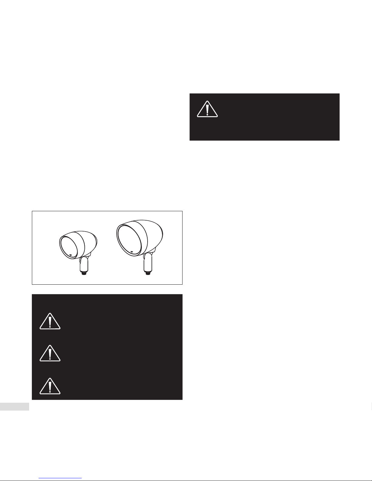
Garden Oasis Premium Satellite Speakers
The Garden Oasis series Satellite speakers are premium
sounding all season outdoor speakers ideal for backyards
ranging from 2,000 to 3,000 sq. feet.
GO4 and GO6 are sold individually and can be ordered in
accordance with the area to be covered.
Made of durable UV treated ABS plastic, Garden Oasis
speakers can endure the elements while providing
years of trouble free service.
While installation is relatively easy, Paradigm’s Garden
Oasis series is designed to be installed by your authorized
Paradigm dealer.
WARNING!
• ACCOUNT FOR POTENTIAL ELECTRICAL,
GAS, BURIED CABLES, PLUMBING OR
OTHER OBSTACLES BEFORE INSTALLING
GROUND STAKES.
• MANY LOCALITIES FORBID DIGGING
WITHOUT PRIOR NOTIFICATION.
CONTACT LOCAL AUTHORITIES BEFORE
INSTALLATION.
• READ AND FOLLOW all instructions
before beginning installation.
PLEASE NOTE: CONTENTS OF GO4 AND
GO6 SATELLITE SPEAKERS DO NOT
CONTAIN MOUNTING OPTIONS. YOU
MUST PURCHASE MOUNTING OPTIONS
SEPARATELY:
Contents of GO4 and GO6:
• (1) Speaker with Mounting Arm
• (1) Off-Season Speaker Cover
• (2) Silicone-Filled Wire Connectors
Mounting Options (Sold Separately):
• Ground Stake
• Surface Mount
• Inground Conduit Box
Required Tools:
• Shovel
• Cable Strippers
• Phillips Screwdriver
• Wrench
Power
Crown Amplifier (available direct from Paradigm).
The Paradigm GO4 and GO6 are passive speakers. These
speakers are optimized for use with the Crown CDi 1000
amplifier which is pre-programmed with customized
DSP settings for a variety of different speaker/subwoofer
installation scenarios.
OVERVIEW
GO6
GO4
Page 5
4EN |
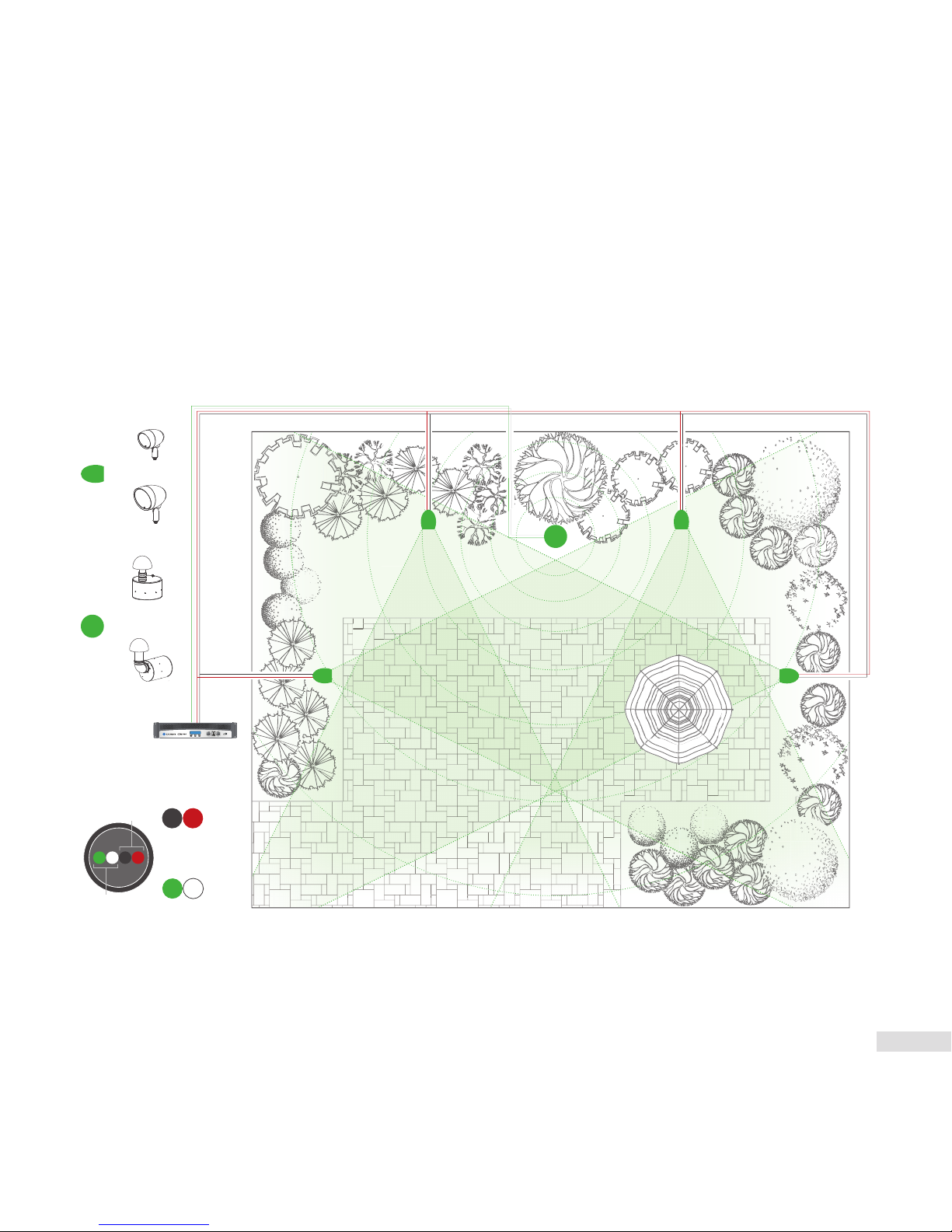
PLANNING THE INSTALL
=
=
GO4
GO6
GO10SW
GO12SW
or
or
Crown Amplifier
4 Conductor Burial Wire
Subwoofer
Speakers
–
+
–
+
Black Re d
Green White
+
–
–
+
• Identify the location.
• Determine the positioning of subwoofer and
satellite speakers.
• Dig the trench according to speakers and
accessories to be installed.
• The trench should be 6”-8” deep.
Page 6

5 | EN
We strongly recommend using burial–rated cable (not
included) when installing any of the Garden Oasis Satellite
Speakers. In addition, it’s critical to use the proper speaker
cable gauge. Please review the chart below.
There a few considerations before you start digging a trench:
• Ensure that ALL Speakers are tested prior to installation.
• Ensure that the proposed area is easily accessed and that
the area is not prone to flooding, standing water or where
the speakers can be easily damaged, kicked or struck.
• Consider Overall Landscape/Garden Design and
positioning in relation to listening area
CABLE RECOMMENDATIONS
INSTALLATION CONSIDERATIONS
CABLE GAUGE CHART
Cable Gauge Distance
18 Gauge Up to 100 feet (30 meters)
16 Gauge Up to 150 feet (45 meters)
14 Gauge Up to 200 feet (61 meters)
12 Gauge Up to 400 feet (122 meters)
10 Gauge Up to 650 feet (198 meters)
Page 7
6EN |
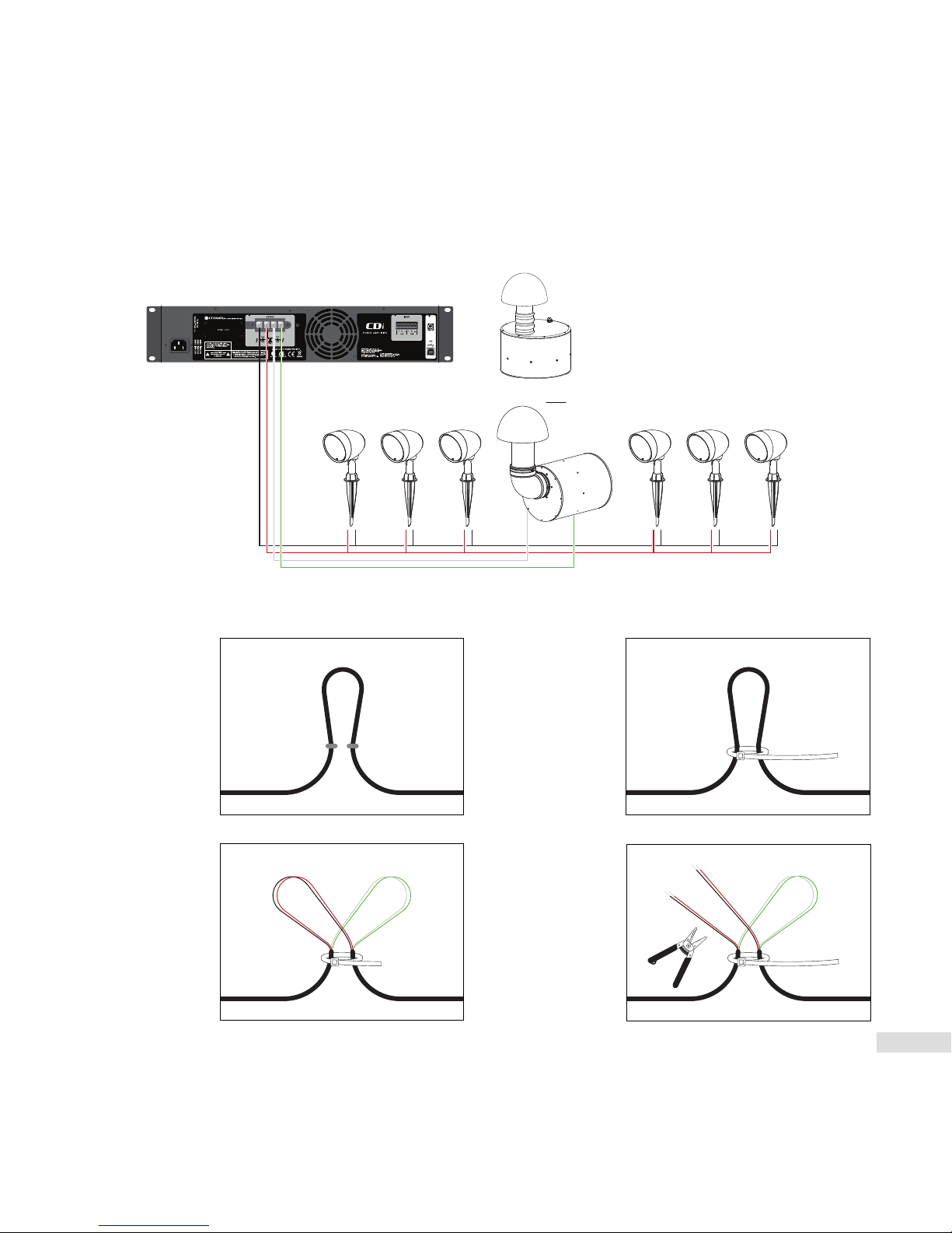
Mono Setup Using 4 Conductor Burial Cable & Crown Amplifier
Preparing the 4 Conductor Burial Cable
WIRING & SPEAKER INSTALLATION
1. Starting
with the first
speaker and
every speaker/
sub that
comes after,
create a loop
approximately
6” in length.
3. Use a Round
Cable Stripper
to remove the
outside protective
cable jacket to
expose the four
color-coded
wires. Separate
the wire loops
as shown.
2. Recommended:
Use a wire tie
(not included)
to keep the wire
loop intact and
act as a strain
relief.
4. Cut the red (+)
and black (-)
wires with cable
strippers and
strip off 1 inch
(25.4mm) of
insulation from
the ends if the
wires to expose
the copper
conductor.
Wires for
Speaker
red (+) &
black (-)
Wires for
Subwoofer
white (+) &
green (-)
Mono Mono Mono MonoMono Mono
GOSW12
GOSW10
OR
Page 8
7 | EN
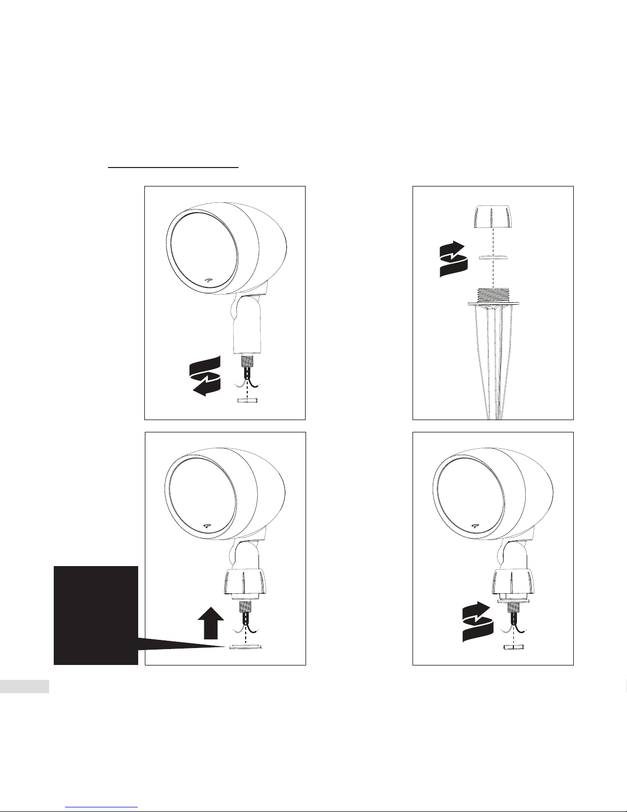
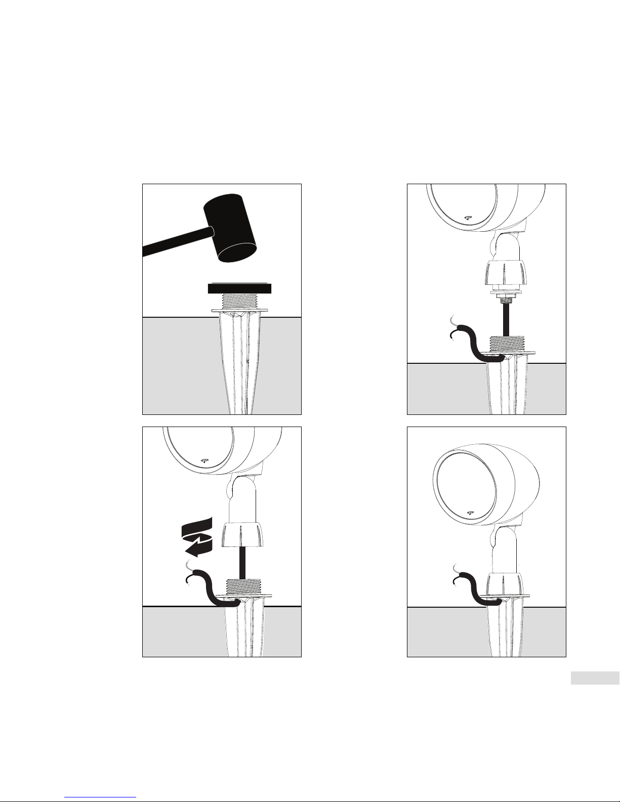
Installing Ground Stake Accessory & Attaching Speaker
1. Remove nut from
the threaded end
of the speaker arm.
3. Slide the twist cap
over the speaker
arm then slide
the gasketed
aluminum washer
(from the ground
stake) over the
threaded end of
speaker arm.
4. Using a wrench,
thread and firmly
tighten the nut
(removed in
step 1) over the
threaded end of
the speaker arm.
2. Remove the twist
cap and gasketed
aluminum washer
from the ground
stake accessory.
WIRING & SPEAKER INSTALLATION (CONT’D)
IMPORTANT!
The face of
the aluminum
washer with the
smaller rubber
gasket must be
facing up.
Page 9
8EN |
7. To attach the
speaker to the
ground stake,
hand thread the
twist cap to the
ground stake.
8. The speaker is
now mounted to
the ground stake.
The next step is
wiring, go the
‘Wiring’ section
for instructions.
For wiring instructions see ‘Speaker & Burial Cable Connections’ on page 11.
6. Thread the
speaker’s wiring
through the
wiring hole in
the ground stake.
5. Using a mallet and
a wooden block,
pound the ground
stake into the
ground. Drive the
ground stake down
until the ground
stake flange is
nearly flush with
the surface. Note:
Leave a slight
gap between the
ground stake
flange and the
ground surface
in order to thread
speaker wiring
through the wiring
hole in the ground
stake.
Page 10
9 | EN
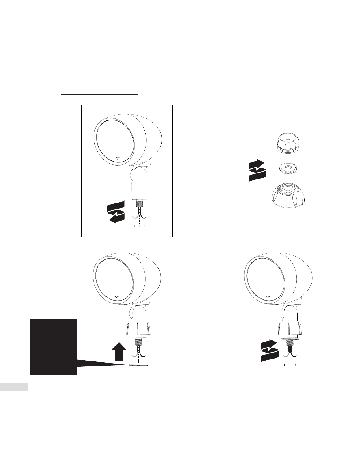
Installing Surface Mount Accessory & Attaching Speaker
1. Remove nut from
the threaded end
of the speaker arm.
3. Slide the twist cap
over the speaker
arm then slide
the gasketed
aluminum washer
(from the ground
stake) over the
threaded end of
speaker arm.
4. Using a wrench,
thread and firmly
tighten the nut
(removed in step 1)
over the threaded
end of the speaker
arm.
2. Remove the twist
cap and gasketed
aluminum washer
from the surface
mount accessory.
WIRING & SPEAKER INSTALLATION (CONT’D)
IMPORTANT!
The face of
the aluminum
washer with the
smaller rubber
gasket must be
facing up.
Page 11
10EN |
6. To attach the
speaker to the
surface mount
base: a) First
hand thread the
twist cap to the
surface mount
base. b) Now
firmly tighten the
twist cap with the
provided wrench.
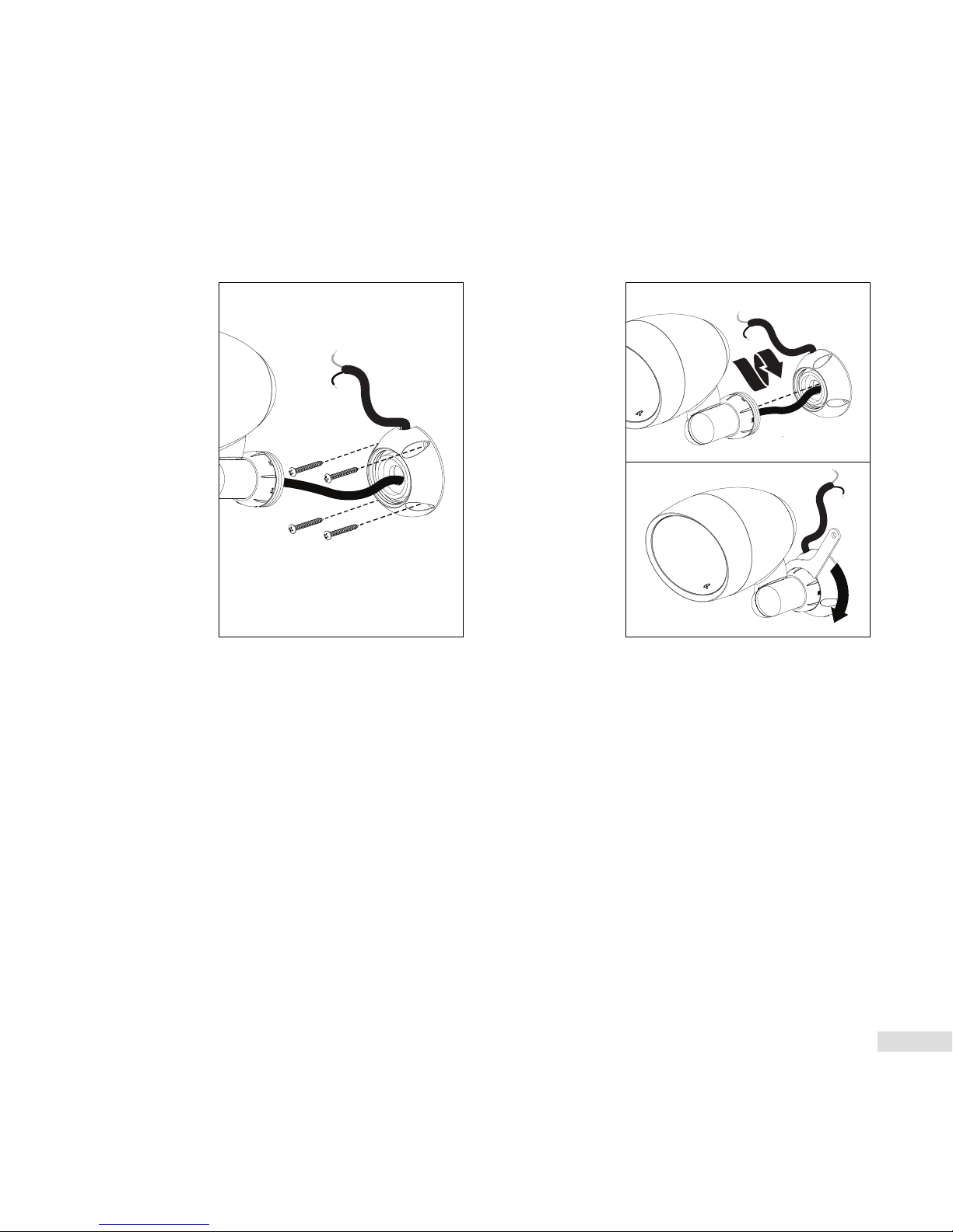
5. Thread the speaker
wire through the
center hole and
out of the wire
opening on the
surface mount
base. Place surface
mount base flush
against the surface
you wish to install
your speaker. To
attach surface
mount base to
the surface, use
appropriate screws
(not supplied) for
your installation.
For specifications
on screws, see your
dealer for details.
Note: For a wall mounted installation where a wire
connection is contained within the surface mount base,
please follow these instructions. It is recommend that the
speaker wire be cut short and the wire sleeve should be
removed to expose the red (+) and black (-) wires. Follow
steps 6 a-b, but do not attach the assembled speaker with
surface mount base until your wire connections are made
with silicone-filled wire connectors covering the exposed
wire connections. The wire connections with siliconefilled wire connectors must be stuffed inside the surface
mount base before attaching to the desired surface with
appropriate screws (not supplied) for your installation. For
specifications on screws, see your dealer for details.
a)
b)
For wiring instructions see ‘Speaker &
Burial Cable Connections’ on page 11.
Page 12

11 | EN
Speaker & Burial Cable Connections
Speaker Direction & Settings
1. Aim the speaker by loosening the screw in the
speaker arm and re-tightening once the desired aim is
achieved.
2. Once your system is setup, set the dial on each
satellite speaker to correspond with the number of
satellite speakers and subwoofers in the installation
(see ‘Audio Settings Chart’ on page 15).
1
0
0
V
O
L
T
S
7
0
V
O
L
T
S
8 ohm 8 ohm
7.5 W3.75 W
15 W 7.5 W
30W
30 W30 W
15 W
GO4
Combine and twist
(clockwise) the red
wires (as shown in
the diagram) from
the amp, speaker
and to the next
speaker. Secure
these three wires
using the provided
silicone-filled
wire connectors;
Repeat procedure for Black wires. NOTE: you may have
to cut some of the speaker cable emanating from the
speaker to a more manageable size.
WIRING & SPEAKER INSTALLATION (CONT’D)
To Speaker
To Amp
To Adjoining
Speaker
Page 13

12EN |
Following the same instructions outlined for the ground stake
or surface mount accessory. The Garden Oasis Inground
Conduit Box can be substituted. Knock out holes in the
Inground Conduit Box as needed. Conduit is sold separately.
Included:
• (1) Inground Conduit Box
•
(1)
Two Piece Mounting Post
• (8) Stainless Steel Screws
• (4) Ground Stakes
Recommended Tools:
• Drill
• PVC Glue – for PVC conduit or fittings
• Silicone Caulk
• Shovel
• Hammer
• #2 Phillips Screwdriver
• Wrench
Installation Instructions
*IMPORTANT! Test your system before gluing
or caulking any part of the Inground Conduit
Box or any conduit piping connections. Use
silicone caulk to seal any openings used for cable.
Allow caulk and glue to dry completely before burying
the Inground Conduit Box.
OPTION 1: PVC Conduit Installation – Knock out the conduit
openings to be used. Glue the conduit piping to the Inground
Conduit Box.* Draw the cable through the conduit and pull at
least 8 inches of cable into the box cavity.
Note: The Inground Conduit Box openings are 3/4” in diameter.
Other conduit piping sizes may be used with adapters.
OPTIONAL INGROUND CONDUIT BOX
Page 14

13 | EN
OPTIONAL INGROUND CONDUIT BOX (CONT’D)
TEST SYSTEM
OPTION 2: Inground Cable Installation – Drill a hole into the
center of the knock out slightly larger than the cable. Route
the cable through and pull at least 8 inches of cable into the
box cavity. Seal the entrance completely with silicone.* Place
the Inground Conduit Boxes in their appropriate trench
location, ensuring a minimum depth of 6 inches.
3. Install the satellite speaker to the Inground Conduit Box
lid, using the two piece post. Use silicone in the threads
to enhance sealing of the Inground Conduit Box against
moisture.*
4. Use the silicone-filled wire connectors included with the
speaker to terminate the wiring connections. Turn the
silicone-filled wire connectors clockwise by hand until
they are tight.
5. The box may now be closed. A weatherproof gasket is
attached to the cover, but for additional water intrusion
protection, line the inside edge of the cover with silicone
where it contacts the box, then assemble the box using
the 8 screws.* Tighten the screws tightly by hand with a
#2 screwdriver.
6. Anchor Inground Conduit Box in the hole using the 4
provided stakes. Install all speakers and test the system
before burying the boxes and wiring.
7. Using a screw driver, adjust the speaker angle and
position last.
*See ‘Important!’ notice on the previous page.
After all satellites and subwoofer connections are
completed, connect the wires to your receiver or amplifier.
IMPORTANT: Be sure not to let any stray’+’ and’-’ strands
touch each other. Touching strands will cause a short
circuit which could damage your amplifier.
Turn your receiver or amplifier ‘On’ and test the system with
your favorite music. If the speakers are operating properly,
refill the wire trench and enjoy your new speakers.
Page 15

14EN |
Don’t be fooled by your amplifier’s volume control. It
adjusts listening level—it does not indicate power output.
If your speakers begin to sound harsh or grating, or if
you hear the bass breaking up, turn the volume down
immediately or you will damage your speakers! This type
of damage constitutes abuse and is not covered by the
warranty!
Tone controls and equalizers can demand even more
power from an amplifier, lowering the point at which it
produces clipping distortion. Use them sparingly, if at all,
and do not use them when listening at loud levels.
Outdoors there are no walls to contain sound. Background
noise is louder and the distance listeners are from the
speaker(s) is usually greater. Achieving a reasonable
listening level can be more difficult. The tendency is to
turn up the volume, however this may disturb neighbors
and when turned up too high, can seriously damage the
speakers or your amplifier.
The solution? In larger areas we recommend using
multiple Paradigm Garden Oasis speakers. Using more
speakers ensures that sound is evenly distributed,
allowing for reasonable listening levels at lower volumes.
Demand on the amplifier is reduced and neighbors are
not disturbed. Think of it this way: When lighting a large
outdoor area, using multiple floodlights on a dimmer set
to a low setting is far more effective than using a single
floodlight with the dimmer set to high.
TO AVOID SPEAKER DAMAGE
LISTENING OUTDOORS
During the off season, when your speakers are not in
use for prolonged periods, you can cover your speakers
from the elements using the cover included. This cover
is breathable, while protecting your speaker for harsh,
inclement weather.
OFF SEASON SPEAKER COVER
Page 16

15 | EN
AUDIO SETTINGS CHART
INSTALLATION USING LONG WIRES (100 feet or longer)
CHANNEL #1
ON AMP
CHANNEL #2
ON AMP
PRESETS ON
CROWN AMP
PRESET
NAME
POWER
OUTPUT
SET DIAL ON SATELLITE SPEAKER
Wire Product
to Channel #1
on the Crown
Amplifier
Wire Product
to Channel #2
on the Crown
Amplifier
Select the Preset
number on the
Crown Amplifier
specified below
Signal level
provided to
subwoofer /
speakers
Remove the cap from the rear of
the satellite speaker and position
the dial to the appropriate
wattage setting below
GO10SW or GO12SW
plus GO4 or GO6
satellite speakers
GO10SW GO4
Preset 2 for
GO10SW and GO4
GO4_10SW
8 ohm / 70V
hybrid
Speakers: 1-12 30W (or less)
GO10SW GO6
Preset 3 for
GO10SW and GO6
GO6_10SW
8 ohm / 70V
hybrid
Speakers: 13-24 15W (or less)
GO12SW GO4
Preset 4 for
GO12SW and GO4
GO4_12SW
8 ohm / 70V
hybrid
Speakers: 25-50 7.5W (or less)
GO12SW GO6
Preset 5 for
GO12SW and GO6
GO6_12SW
8 ohm / 70V
hybrid
Speakers: 50-100 3.8W (or less)
NO subwoofer and
GO4 or GO6 satellite
speakers
GO4 GO4
Preset 10 for
GO4 in Mono
GO_4_MO NA / 70V Speakers: 1-12 30W (or less)
GO6 GO6
Preset 11 for
G06 in Mono
GO_6_MO NA / 70V Speakers: 13-24 15W (or less)
GO4 GO4
Preset 12 for
GO4 in Stereo
GO_4_ST NA / 70V Speakers: 25-50 7.5W (or less)
GO6 GO6
Preset 13 for
GO6 in Stereo
GO_6_ST NA / 70V Speakers: 50-100 3.8W (or less)
INSTALLATION USING SHORT WIRES (less than 100 feet) FOR 4 OR FEWER SPEAKERS
CHANNEL #1
ON AMP
CHANNEL #2
ON AMP
PRESETS ON
CROWN AMP
PRESET
NAME
POWER
OUTPUT
SET DIAL ON SATELLITE SPEAKER
Wire Product
to Channel #1
on the Crown
Amplifier
Wire Product
to Channel #2
on the Crown
Amplifier
Select the Preset
number on the
Crown Amplifier
specified below
Signal level
provided to
subwoofer /
speakers
Remove the cap from the rear of
the satellite speaker and position
the dial to the appropriate
wattage setting below
GO10SW or GO12SW
plus 4 or less
GO4 or GO6 satellite
speakers
GO10SW GO4
Preset 6 for
GO10SW and GO4
8GO410SW 8 ohm / 8ohm
8ohms
GO10SW GO6
Preset 7 for
GO10SW and GO 6
8GO610SW 8 ohm / 8ohm
GO12SW GO4
Preset 8 for
GO12SW and GO4
8GO412SW 8 ohm / 8ohm
GO12SW GO6
Preset 9 for
GO12SW and GO6
8GO612SW 8 ohm / 8ohm
No Subwoofer and 4
or less GO4 or GO6
satellite speakers
GO4 GO4
Preset 14 for
GO4 in mono
8GO_4_MO NA / 8ohm
8ohms
GO6 GO6
Preset 15 for
GO6 in mono
8GO_6_MO NA / 8ohm
GO4 GO4
Preset 16 for
GO4 in stereo
8GO_4_ST NA / 8ohm
GO6 GO6
Preset 17 for
GO6 in stereo
8GO_6_ST NA / 8ohm
Page 17

16EN |
Paradigm® Garden Oasis™ Satellite Speakers are
warranted to be and remain free of manufacturing and/
or material defects for a period of three (3) years from
the date of original purchase. Within the time period
specified, repair, replacement or adjustment of parts
for manufacturing and/or material defects will be free
of charge to the original owner. Thermal or mechanical
abuse/misuse is not covered under warranty.
Limitations:
• Warranty begins on date of original retail purchase
from an Authorized Paradigm® Dealer only. It is not
transferable.
• Warranty applies to product in normal residential use
only. If product is subjected to any of the conditions
outlined in the next section, warranty is void.
• Warranty does not apply if the product is used in
professional or commercial applications.
• Warranty also excludes normal cosmetic deterioration
caused by environmental conditions.
Warranty is Void if:
• The product has been abused (intentionally or
accidentally).
• The product has been used in conjunction with
unsuitable or faulty equipment.
• The product has been subjected to damaging signals,
derangement in transport, mechanical damage or any
a normal conditions.
• The product (including cabinet) has been tampered with
or damaged by an unauthorized service facility.
• The serial number has been removed or defaced.
Owner Responsibilities:
• Provide normal/reasonable operating care and
maintenance.
• Provide or pay for transportation charges for product to
service facility.
• Provide proof of purchase (your sales receipt given
at time of purchase from your Authorized Paradigm
®
Dealer must be retained for proof-of-purchase date).
Should servicing be required, contact your nearest
Authorized Paradigm
®
Dealer, Paradigm Electronics Inc.
or Import Distributor (outside the U.S. and Canada) to
arrange, bring in or ship prepaid, any defective unit. Visit
our website, www.paradigm.com for more information.
Paradigm Electronics Inc. reserves the right to improve
the design of any product without assuming any
obligation to modify any product previously manufactured.
This warranty is in lieu of all other warranties expressed
or implied, of merchantability, fitness for any particular
purpose and may not be extended or enlarged by anyone.
In no event shall Paradigm Electronics Inc., their agents
or representatives be responsible for any incidental or
consequential damages. Some jurisdictions do not allow
limitation of incidental or consequential damages, so this
exclusion may not apply to you.
Retain this manual and your sales receipt for proof of
warranty term and proof of purchase.
LIMITED WARRANTY
Page 18

17 | EN
NOTES
Page 19

GO4
GO4
GO6
GO6
Enceintes
satellites
extérieures
MANUEL DE L’UTILISATEUR
arden
asis
Page 20

1 | FR 121616
Page 21

2FR |
TABLE DES MATIÈRES
Aperçu..........................................3
Enceintes satellites premium Garden Oasis .........3
Outils nécessaires ..............................3
Alimentation...................................3
Planification de l’installation .......................4
Recommendations en matière de câbles .............5
Facteurs liés à l’installation........................5
Installation des câbles et des enceintes..............6
Configuration mono à l’aide de 4 câbles conducteurs
souterrains et d’un amplificateur Crown............6
Préparation des 4 câbles conducteurs souterrains ...6
Installation d’accessoire de piquet de terre et ........
fixation des enceintes ...........................7
Installation d’accessoire de montage en surface et ...
fixation des enceintes ...........................9
Raccordement entre l’enceinte et le câble souterrain ..11
Orientation et paramètres des enceintes ..........11
Boîte de raccordement souterraine facultative ......12
OPTION 1 : Installation avec conduit en PVC........12
OPTION 2 : Installation avec câble souterrain.......12
Tester le système ...............................13
Pour éviter les dommages aux enceintes ...........14
Écoute à l’extérieur .............................14
Couvercle d’enceinte hors saison ..................14
Tableau des préréglages .........................15
Garantie limitée.................................16
Page 22

3 | FR
Enceintes satellites premium Garden Oasis
Les enceintes satellites de la série Garden Oasis sont des
enceintes extérieures toutes saisons au son exceptionnel,
parfaites pour les cours de 2000 à 3 000 pieds carrés.
Les modèles GO4 et GO6 sont vendus individuellement et
peuvent être commandés en fonction de la zone à couvrir.
Faites de plastique ABS durable traité contre les rayons UV,
les enceintes Garden Oasis peuvent résister aux éléments
tout en offrant des années de fonctionnement sans tracas.
Bien que l’installation soit relativement facile, les enceintes
de la série Garden Oasis de Paradigm sont conçues pour
être installées par votre revendeur Paradigm autorisé.
MISE EN GARDE!
• TENEZ COMPTE DES FILS ÉLECTRIQUES,
DES CONDUITES DE GAZ, DES CÂBLES
SOUTERRAINS, DES TUYAUX DE PLOMBERIE
ET DES AUTRES OBSTACLES AVANT
D’INSTALLER LES PIQUETS DE TERRE.
• DE NOMBREUSES LOCALITÉS INTERDISENT
DE CREUSER SANS PRÉAVIS. COMMUNIQUEZ
AVEC LES AUTORITÉS LOCALES AVANT
L’INSTALLATION.
• VEUILLEZ LIRE ET SUIVRE toutes les
instructions avant de commencer l’installation.
VEUILLEZ NOTER : LE CONTENU DES
ENCEINTES SATELLITES GO4 ET GO6
NE COMPREND PAS LES OPTIONS DE
MONTAGE. VOUS DEVEZ ACHETER LES
OPTIONS DE MONTAGE SÉPARÉMENT.
Contenu de GO4 et GO6 :
• (1) Enceinte avec bras de montage
• (1) Couvert d’enceinte hors saison
• (2) Capuchons de câble remplis de silicone
Options de montage (vendues séparément) :
• Piquet de terre
• Montage en surface
• Boîte de raccordement souterraine
Outils nécessaires :
• Pelle
• Pinces à dénuder
• Tournevis Phillips
•
Clé à molette
Alimentation
Amplificateur Crown (disponible directement de
Paradigm).
Les enceintes CO4 et CO6 de Paradigm sont des
enceintes passives. Ces enceintes sont optimisées pour
une utilisation avec l’amplificateur Crown CDi 1000 qui
est préprogrammé avec des paramètres DSP sur mesure
pour différents scénarios d’installation d’enceintes/
caissons de sous-graves.
APERÇU
GO6
GO4
Page 23

4FR |
PLANIFICATION DE L’INSTALLATION
=
=
GO4
GO6
GO10SW
GO12SW
–
+
–
+
+
–
ou
ou
Amplificateur Crown
4 câbles conducteurs
souterrains
Caisson de
sous-graves
Enceintes
Noir Rouge
Vert Blanc
–
+
• Déterminez l’emplacement.
• Déterminez le positionnement du caisson de sousgraves et des enceintes satellites.
• Creusez la tranchée en fonction des enceintes et des
accessoires à installer.
• La tranchée doit avoir une profondeur de 6 à 8 po.
Page 24

5 | FR
Nous vous recommandons fortement d’utiliser un câble de
type souterrain (non compris) lorsque vous installez tout type
d’enceinte satellite Garden Oasis. De plus, il est essentiel
d’utiliser le bon calibre de câble d’enceinte. Veuillez consulter
le tableau ci-dessous.
Vous devez examiner certains facteurs avant de commencer à
creuser une tranchée :
• Assurez-vous que TOUTES les enceintes sont testées
avant l’installation.
• Assurez-vous que la zone envisagée est facilement
accessible et qu’elle n’est pas exposée aux inondations,
à l’eau stagnante, ou que la zone n’est pas un endroit où
les enceintes peuvent être endommagées, écrasées ou
frappées.
• Réfléchissez au design de la cour et à l’aménagement
paysager général en lien avec la zone d’écoute.
RECOMMENDATIONS EN MATIÈRE DE CÂBLES
FACTEURS LIÉS À L’INSTALLATION
TABLEAU DE CALIBRE DE CÂBLE
Calibre de câble Distance
Calibre 18 Jusqu’à 100 pieds (30 mètres)
Calibre 16 Jusqu’à 150 pieds (45 mètres)
Calibre 14 Jusqu’à 200 pieds (61 mètres)
Calibre 12 Jusqu’à 400 pieds (122 mètres)
Calibre 10 Jusqu’à 650 pieds (198 mètres)
Page 25

6FR |
Configuration mono à l’aide de 4 câbles conducteurs souterrains et d’un amplificateur Crown
Préparation des 4 câbles conducteurs souterrains
INSTALLATION DES CÂBLES ET DES ENCEINTES
1. En commençant
par la première
enceinte et
chaque enceinte/
caisson qui vient
après, créez
une boucle
d’une longueur
d’environ 6 po.
3. Utilisez une pince
à dénuder ronde
pour enlever la
gaine de câble
protectrice
extérieure pour
exposer les
quatre câbles à
code de couleur.
Séparez les
boucles de câble
comme illustré.
2. Recommandé :
Utilisez un
serre-câble
(non compris)
pour garder la
boucle de câble
intacte et en tant
réducteur de
tension.
4. Coupez les câbles
rouge (+) et noir
(-) avec la pince à
dénuder et enlevez
un pouce (25,4
mm) d’isolation
des extrémités
afin d’exposer le
conducteur en
cuivre.
Mono Mono Mono MonoMono Mono
GOSW12
GOSW10
OU
Câbles
pour enceinte
rouge (+) et
noir (-)
Câbles
pour caisson
de sous‑graves
blanc (-) et
vert (+)
Page 26

7 | FR
Installation d’accessoire de piquet de terre et fixation des enceintes
1. Enlevez l’écrou
de l’extrémité
filetée du bras
d’enceinte.
3. Glissez la
rondelle
d’étanchéité en
aluminium (du
piquet de terre)
sur l’extrémité
fileté du bras de
l’enceinte.
4. À l’aide d’une clé,
filetez et serrez
fermement
l’écrou (enlevez
à l’étape 1)
sur l’extrémité
filetée du bras de
l’enceinte.
2. Enlevez le
capuchon
dévissable et
la rondelle
d’étanchéité en
aluminium du
piquet de terre.
INSTALLATION DES CÂBLES ET DES ENCEINTES (SUITE)
IMPORTANT!
La face de la
rondelle en
aluminium avec
le petit joint en
caoutchouc doit
être orientée
vers le haut.
Page 27

8FR |
7. Pour fixer l’enceinte
dans le piquet de
terre, filetez à la
main le capuchon
dévissable sur le
piquet de terre.
8. L’enceinte est
maintenant
montée sur le
piquet de terre.
La prochaine
étape est le
câblage; allez à la
section « Câblage
» pour obtenir
des instructions.
6. Filetez le câble
d’enceinte dans
le trou de câblage
du piquet de
terre.
5. À l’aide d’un maillet
et d’un bloc de bois,
enfoncez le piquet
de terre dans le sol.
Enfoncez le piquet
de terre aussi
loin que possible,
jusqu’à ce que la
bride du piquet
soit pratiquement
égale à la surface.
Remarque : Laissez
un espace entre la
bride du piquet de
terre et la surface
du sol afin de
pouvoir fileter le
câble d’enceinte par
le trou de câblage
dans le piquet de
terre.
Page 28

9 | FR
Installation d’accessoire de montage en surface et fixation des enceintes
3. Glissez le capuchon
dévissable sur le
bras de l’enceinte,
puis glissez la
rondelle d’étanchéité
en aluminium (du
piquet de terre) sur
l’extrémité filetée du
bras de l’enceinte.
4. À l’aide d’une clé,
filetez et serrez
fermement
l’écrou (enlevez
à l’étape 1)
sur l’extrémité
filetée du bras de
l’enceinte.
WIRING & SPEAKER INSTALLATION (CONT’D)
1. Enlevez l’écrou
de l’extrémité
filetée du bras
d’enceinte.
2. Enlevez le
capuchon
dévissable et
la rondelle
d’étanchéité en
aluminium du
piquet de terre.
IMPORTANT!
La face de la
rondelle en
aluminium avec
le petit joint en
caoutchouc doit
être orientée
vers le haut.
Page 29

10FR |
6. Pour fixer
l’enceinte à la
base du montage
de surface : a)
Premièrement,
filetez le bouchon
dévissable à
la main sur la
base du montage de surface.
b) Maintenant,
serrez fermement le capuchon
dévissable avec
la clé fournie.
5. Filetez le câble
d’enceinte dans
le trou du centre
et sortez-le par
l’ouverture de
câble sur la base
du montage
de surface.
Placez la base
du montage de
surface à égalité
sur la surface
sur laquelle vous
souhaitez installer
l’enceinte.Pour
fixer la base
du montage
de surface
à la surface,
utilisez les vis
appropriées (non
comprises) pour votre installation.Pour obtenir des
spécifications sur les vis, consultez votre revendeur.
Remarque : Pour une installation avec montage au mur
où une connexion par câble est comprise dans la base du
montage de surface, veuillez suivre ces instructions.Il est
recommandé que le câble d’enceinte soit coupé court,
et la gaine du câble doit être enlevée pour exposer les
câbles rouge (+) et noir (-). Suivez les tapes 6 a-b, mais
ne fixez pas l’enceinte montée sur la base du montage de
surface avant d’avoir fait les connexions de câble avec les
capuchons de câble qui couvrent les connexions de câble
exposées. Les connexions de câble avec les capuchons
de câble doivent être insérées dans la base du montage
de surface avant la fixation sur la surface désirée avec les
vis appropriées (non comprises) pour votre installation.
Pour obtenir des spécifications sur les vis, consultez votre
revendeur.
a)
b)
Pour les instructions concernant
le câblage, consultez la section
« Raccordement entre l’enceinte et
le câble souterrain » à la page 11.
Page 30

11 | FR
Raccordement entre l’enceinte et le câble souterrain
Orientation et paramètres des enceintes
1. Orientez l’enceinte en desserrant la vis dans le bras
de l’enceinte et en la resserrant une fois l’orientation
souhaitée obtenue.
2. Une fois que votre système est configuré, réglez
le cadran sur chaque enceinte satellite afin qu’il
corresponde au nombre d’enceintes satellites et de
caissons de sous-graves de l’installation (voir « Tableau
des préréglages » à la page 15 »).
Combinez et tournez
(sens horaire) les
câbles rouges
(comme illustré dans
le diagramme) de
l’amplificateur, de
l’enceinte et vers la
prochaine enceinte.
Sécurisez ces trois
câbles à l’aide des
capuchons de câble
remplis de silicone; répétez la procédure pour les câbles noirs.
REMARQUE :
vous pourriez devoir couper une certaine partie
du câble d’enceinte qui dépasse de l’enceint pour obtenir une
longueur plus facile à gérer.
INSTALLATION DES CÂBLES ET DES ENCEINTES (SUITE)
1
0
0
V
O
L
T
S
7
0
V
O
L
T
S
8 ohm 8 ohm
7.5 W3.75 W
15 W 7.5 W
30W
30 W30 W
15 W
GO4
vers l’enceinte
vers l’amp
vers la prochaine
enceinte
Page 31

12FR |
En suivant, les mêmes instructions que celles décrites pour
le piquet de terre ou pour le
montage en surface
, la boîte de
raccordement souterraine Garden Oasis peut être substituée.
Défoncez les trous dans la boîte de raccordement souterraine, au
besoin. Le conduit est vendu séparément.
Comprend :
• (1) Boîte de raccordement souterraine
• (1) Poteau de montage en deux pièces
• (8) Vis en acier inoxydable
• (4) Piquets de terre
Outils recommandés :
• Perceuse
• Colle à PVC – pour les conduits ou les raccords en PVC
• Mastic au silicone
• Pelle
• Marteau
• Tournevis Phillips no 2
• Clé à molette
Instructions d’installation
*IMPORTANT! Testez votre système avant de
coller ou de calfeutrer la boîte de raccordement
souterraine ou tout raccord de conduit de
tuyauterie. Utilisez du mastic de silicone pour sceller
toutes les ouvertures utilisées pour les câbles. Laissez
sécher le mastic et la colle entièrement avant d’enterrer
la boîte de raccordement souterraine.
OPTION 1 : Installation avec conduit en PVC – Défoncez les
ouvertures du conduit à utiliser. Collez le tuyau du conduit
sur la boîte de raccordement souterraine. Passez le câble
dans le conduit et tirez au moins 8 pouces de câble dans la
cavité de la boîte.
Remarque : Les ouvertures de boîte de raccordement souterraine
ont un diamètre de
3/4
po. D’autres tailles de tuyauterie de conduite
peuvent être utilisées avec des adaptateurs.
BOÎTE DE RACCORDEMENT SOUTERRAINE FACULTATIVE
Page 32

13 | FR
BOÎTE DE RACCORDEMENT SOUTERRAINE FACULTATIVE (SUITE)
TESTER LE SYSTÈME
OPTION 2 : Installation avec câbles souterrains – Percez
un trou dans le centre de la pièce à défonce, un petit peu
plus grand que le câble. Passez le câble et tirez au moins 8
pouces de câble dans la cavité de la boîte. Scellez entièrement
l’entrée avec du silicone.
Placez les boîtes souterraines dans leur emplacement
approprié dans la tranchée, en vous assurant d’une profondeur
minimale de 6 pouces.
3. Installez l’enceinte satellite sur le couvercle de la boîte
de conduit souterraine, à l’aide du poteau en deux pièces.
Utilisez du silicone dans les filetages pour accroître le
scellage de la boîte de conduit souterraine contre l’humidité.
4. Utilisez les écrous de câble à l’épreuve de l’eau compris
avec l’enceinte pour terminer les raccords de câble. Tournez
l’écrou de câble à la main dans le sens horaire, jusqu’à ce
qu’ils soient serrés.
5. La boîte peut maintenant être fermée. Un joint à l’épreuve
de l’eau est fixé sur le couvercle, mais pour obtenir une
protection accrue conte l’infiltration d’eau, appliquez du
silicone sur le rebord intérieur du couvercle où il entre en
contact avec la boîte, puis assemblez la boîte à l’aide des
8 vis. Serrez les vis fermement à la main, puis avec un
tournevis no 2.
6. Ancrez la boîte de raccordement souterraine dans le trou à
l’aide des 4 piquets fournis. Installez toutes les enceintes et
testez le système avant d’enterrer les boîtes et les câbles.
7. À l’aide d’un tournevis, ajustez l’angle et la position de
l’enceinte.
*Voir l’avis « Important! » à la page précédente.
Une fois que tous les raccordements des enceintes satellites et
des caissons de sous-graves sont terminés, raccordez les câbles à
votre récepteur ou amplificateur.
IMPORTANT : Assurez-vous de ne pas laisser aucun brin de
câble + et - se toucher. Les brins de câble qui se touchent
causeront un cours circuit qui peut endommager votre
amplificateur.
Allumez votre récepteur/amplificateur et testez le système
avec votre musique favorite. Si les enceintes fonctionnement
adéquatement, remplissez la tranchée et profitez de vos nouvelles
enceintes.
Page 33

14FR |
Ne vous laissez pas avoir par la commande de volume
de votre amplificateur. Elle ajuste le niveau d’écoute –
elle n’indique pas la puissance de sortie. Si vos enceintes
commencent à produire un son dur ou râpeux, ou si les
graves se brisent, baissez immédiatement le volume afin
de ne pas endommager les enceintes! Ce type de dommage
constitue une utilisation abusive est n’est pas couvert par
la garantie.
Les commandes de ton et les égalisateurs peuvent
demander encore plus de puissance d’un amplificateur,
ce qui abaisse le point auquel il produit une distorsion
d’écrêtage. Utilisez-les avec parcimonie, si vous les
utilisez, et ne les utilisez pas lors d’une écoute à des
niveaux élevés.
À l’extérieur, il n’y a pas de murs pour contenir le son.
Les bruits de fond sont plus forts et habituellement, les
auditeurs sont plus loin des enceintes. Il peut être plus
difficile d’obtenir un niveau d’écoute raisonnable. Les
gens ont tendance à monter le volume; toutefois, cela peut
déranger les voisins, et lorsque le volume est trop haut,
cela peut endommager les enceintes ou l’amplificateur.
La solution? Dans les zones plus grandes, nous
recommandons d’utiliser plusieurs enceintes Paradigm
Gardent Oasis. L’utilisation de plusieurs enceintes
permet de s’assurer que le son est distribué
uniformément, ce qui permet des niveaux d’écoute
raisonnables à des volumes plus bas. La demande sur
l’amplificateur est diminuée et les voisins ne sont pas
dérangés. Voyez les choses de la façon suivante : lorsque
vous éclairez une grande zone extérieure, l’utilisation
de projecteurs avec un gradateur à un réglage bas
est beaucoup plus efficace que l’utilisation d’un seul
projecteur avec un gradateur à un réglage trop élevé.
Pendant la basse saison, lorsque les enceintes ne sont
pas utilisées pendant une période prolongée, vous pouvez
couvrir les enceintes à l’aide du couvercle fourni. Ce
couvercle respire, tout en protégeant votre enceinte des
intempéries.
POUR ÉVITER LES DOMMAGES AUX ENCEINTES
ÉCOUTE À L’EXTÉRIEUR
COUVERCLE D’ENCEINTE HORS SAISON
Page 34

15 | FR
TABLEAU DES PARAMÈTRES AUDIO
INSTALLATION AVEC DES CÂBLES LONGS (100 pi ou plus)
CANAL NO 1
SUR AMP
CANAL NO 2
SUR AMP
PRÉRÉGLAGES
SUR AMP CROWN
NOM
PRÉRÉGLÉ
PUISSANCE
DE SORTIE
RÉGLER CADRAN SUR
ENCEINTE SATELLITE
Raccordez le produit
au Canal no 1 sur
l’amplificateur
en couronne
Raccordez le produit
au Canal no 2 sur
l’amplificateur
en couronne
Choisissez le
numéro préréglé sur
l’amplificateur Crown
indiqué ci-dessous
Niveau de signal
fourni au caisson
de sous-graves/
enceintes
Enlevez le couvert de la partie
arrière de l’enceinte satellite et
placez le cadran au numéro
indiqué ci-dessous.
GO10SW ou GO12SW
plus enceintes
satellites GO4 ou GO6
GO10SW GO4
Préréglé 2 pour
GO10SW et GO4
GO4_10SW
8 ohm / 70V
hybride
Enceintes: 1-12 30W (ou moins)
GO10SW GO6
Préréglé 3 pour
GO10SW et GO6
GO6_10SW
8 ohm / 70V
hybride
Enceintes: 13-24 15W (ou moins)
GO12SW GO4
Préréglé 4 pour
GO12SW et GO4
GO4_12SW
8 ohm / 70V
hybride
Enceintes: 25-50 7.5W (ou moins)
GO12SW GO6
Préréglé 5 pour
GO12SW et GO6
GO6_12SW
8 ohm / 70V
hybride
Enceintes: 50-100 3.8W (ou moins)
AUCUN caisson
de sous-graves et
enceintes satellites
GO4 ou GO6
GO4 GO4
Préréglé 10 pour
GO4 en Mono
GO_4_MO na / 70V Enceintes: 1-12 30W (ou moins)
GO6 GO6
Préréglé 11 pour
G06 en Mono
GO_6_MO na / 70V Enceintes: 13-24 15W (ou moins)
GO4 GO4
Préréglé 12 pour
GO4 en stéréo
GO_4_ST na / 70V Enceintes: 25-50 7.5W (ou moins)
GO6 GO6
Préréglé 13 pour
GO6 in stéréo
GO_6_ST na / 70V Enceintes: 50-100 3.8W (ou moins)
INSTALLATION AVEC LES CÂBLES COURTS (moins de 100 pieds) POUR 4 ENCEINTES OU MOINS
CANAL NO 1
SUR AMP
CANAL NO 2
SUR AMP
PRÉRÉGLAGES
SUR AMP CROWN
NOM
PRÉRÉGLÉ
PUISSANCE
DE SORTIE
RÉGLER CADRAN SUR
ENCEINTE SATELLITE
Raccordez le produit
au Canal no 1 sur
l’amplificateur
en couronne
Raccordez le produit
au Canal no 2 sur
l’amplificateur
en couronne
Choisissez le
numéro préréglé sur
l’amplificateur Crown
indiqué ci-dessous
Niveau de signal
fourni au caisson
de sous-graves/
enceintes
Enlevez le couvert de la partie
arrière de l’enceinte satellite et
placez le cadran au numéro
indiqué ci-dessous.
GO10SW ou GO12SW
plus 4 enceintes
satellites GO4 ou GO6
ou moins
GO10SW GO4
Préréglé 6 pour
GO10SW et GO 4
8GO410SW 8 ohm / 8ohm
8ohms
GO10SW GO6
Préréglé 7 pour
GO10SW et GO 6
8GO610SW 8 ohm / 8ohm
GO12SW GO4
Préréglé 8 pour
GO12SW et GO4
8GO412SW 8 ohm / 8ohm
GO12SW GO6
Préréglé 9 pour
GO12SW et GO 6
8GO612SW 8 ohm / 8ohm
Aucun caisson de
sous-graves plus 4
enceintes satellites
GO4 ou GO6 ou moins
GO4 GO4
Préréglé 14 pour
GO4 en mono
8GO_4_MO nd / 8ohm
8ohms
GO6 GO6
Préréglé 15 pour
GO6 en mono
8GO_6_MO nd / 8ohm
GO4 GO4
Préréglé 16 pour
GO4 en stéréo
8GO_4_ST nd / 8ohm
GO6 GO6
Préréglé 17 pour
GO6 en stéréo
8GO_6_ST nd / 8ohm
Page 35

16FR |
Les enceintes ParadigmMD Garden Oasis sont garanties
contre les défauts de matériaux et de fabrication pendant
une période de trois (3) ans à compter de la date
d’achat d’origine. Durant cette période, la réparation, le
remplacement ou le réglage de pièces pour des défauts de
matériaux ou de fabrication ne seront pas à la charge du
premier acheteur. Les dommages causés par l’exposition
abusive à la chaleur ou l’usage abusif ne sont pas couverts
par la présente garantie.
Restrictions :
• La garantie entre en vigueur à la date d’achat d’origine
chez un revendeur autorisé ParadigmMD seulement. La
garantie n’est pas transférable.
• La garantie s’applique au produit pour une utilisation
résidentielle normale uniquement. Si le produit
est assujetti à l’une des conditions définies dans le
paragraphe suivant, la garantie est annulée.
• La garantie ne s’applique pas à un usage commercial ou
professionnel.
• La garantie exclut la détérioration cosmétique normale
causée par les conditions environnementales.
La garantie est annulée si :
• Le produit est assujetti à un usage abusif (accidentel ou
intentionnel);
• Le produit est utilisé avec du matériel défectueux ou non
adéquat;
• Le produit est soumis à des signaux électriques
dommageables, un transport dangereux, des dommages
mécaniques ou toute autre condition anormale;
• Le produit (y compris le boîtier) est altéré ou
endommagé lors d’une réparation non autorisée;
• La plaque du numéro de série de l’enceinte est enlevée
ou défigurée.
Responsabilités du propriétaire :
• Apporter un soin et un entretien normaux et
raisonnables;
• Fournir ou assumer les frais de transport jusqu’à
l’atelier de réparation;
• Fournir une preuve d’achat (conserver le reçu fourni lors
de l’achat par le revendeur autorisé Paradigm
MD
comme
preuve de la date d’acquisition).
Si une réparation est nécessaire, contactez le revendeur
autorisé Paradigm
MD
, Paradigm Electronics Inc. ou le
distributeur à l’étranger (à l’extérieur du Canada et des
États-Unis) pour planifier l’envoi prépayé de l’appareil
défectueux. Consultez le site Web www.paradigm.com pour
plus d’information.
Paradigm Electronics Inc. se réserve le droit d’améliorer la
conception de tout produit sans obligations de modifier tout
produit déjà fabriqué.
La présente garantie tient en lieu et place de toute autre
garantie, explicite ou implicite, de qualité marchande et
d’adéquation pour tout usage particulier, et ne peut être
élargie ou étendue par quiconque. Paradigm Electronics
Inc. et ses représentants ou agents ne peuvent pas être
tenus responsables de dommages indirects ou consécutifs
découlant de l’utilisation de ces produits en aucun cas.
Dans les endroits où une réglementation spécifique interdit
une telle limitation de la responsabilité, cette exclusion ne
s’applique pas.
Conserver le présent manuel et le reçu comme preuve
d’achat et de garantie.
GARANTIE LIMITÉE
Page 36

17 | EN
NOTES
 Loading...