

Panasonic WV-S2570L User Manual
Operating Instructions
WV-S2570L
WV-S2270L
WV-S1570L
Network Camera
Model No. WV-S2570L
WV-S2270L
WV-S1570L
The model number is abbreviated in some descriptions in this manual.

Preface
Preface
About the user manuals
There are 3 sets of operating instructions as follows.
• Operating Instructions (this document): Explains how to perform the settings and how to operate this
camera.
• Important Information: Provides information about the cautions required for safely using and installing this
camera.
• Installation Guide: Explains how to install and connect devices.
The screens used in these operating instructions show the case of WV-S2570L. Depending on the model used,
the screens shown in the explanations may differ to the actual camera screens.
Note
• “Control No.:C****” used in this document should be used to search for information on the Panasonic
support website and will guide you to the right information.
Abbreviations
The following abbreviations are used in these operating instructions.
Microsoft Windows 10 is described as Windows 10.
Microsoft Windows 8.1 is described as Windows 8.1.
Microsoft Windows 7 is described as Windows 7.
Internet Explorer 11 is described as Internet Explorer.
SDXC/SDHC/SD memory card is described as SD card or SD memory card.
Universal Plug and Play is described as UPnP™ or UPnP.
2 Operating Instructions
For administrator registration
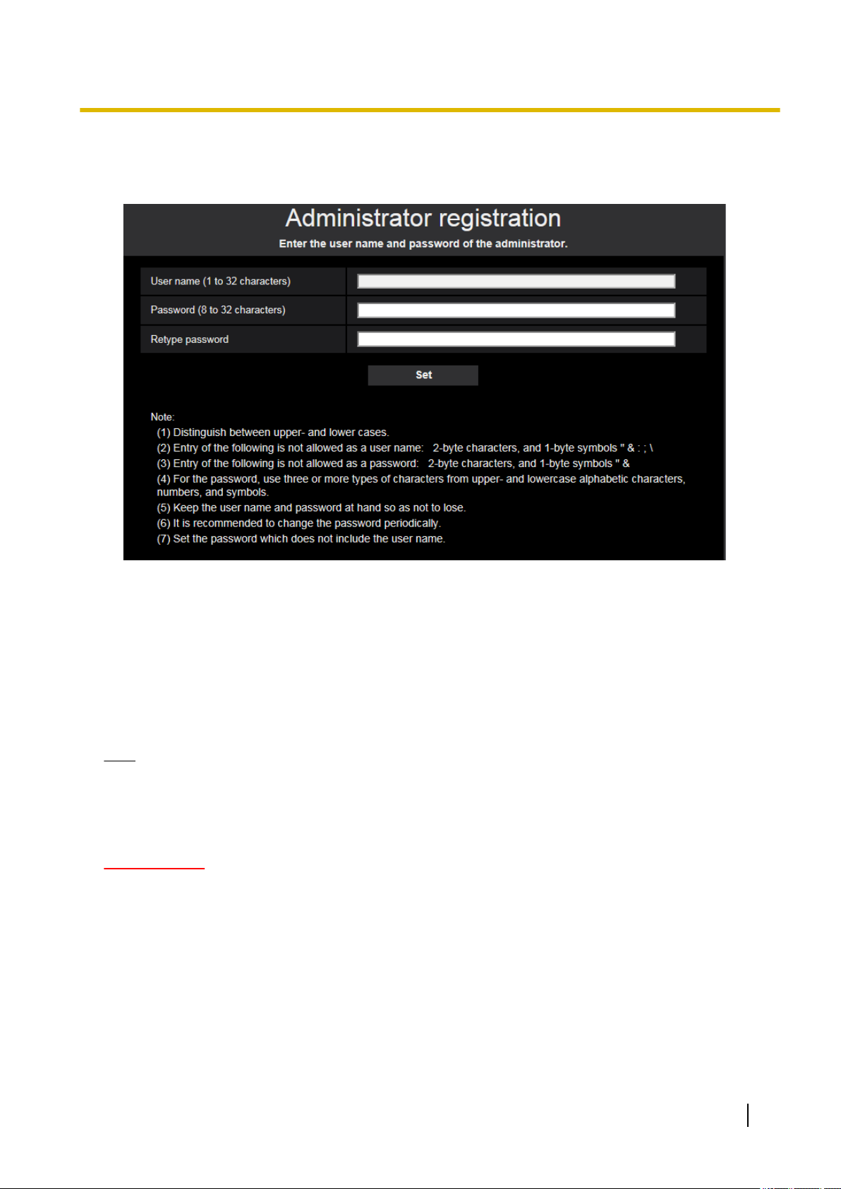
At the time of first access to the camera (or at the time of initialization), the registration screen will be displayed.
Preface
[User name (1 to 32 characters)]
Enter the user name of the administrator.
Available number of characters: 1 - 32 characters
Unavailable characters: 2-byte characters, and 1-byte symbols " & : ; \
[Password (8 to 32 characters)]/[Retype password]
Enter the administrator password.
Available number of characters: 8 - 32 characters
Unavailable characters: 2-byte characters, and 1-byte symbols " &
Note
• Distinguish between upper- and lower cases.
• For the password, use three or more types of characters from upper- and lowercase alphabetic
characters, numeric characters, and symbols.
• Set the password which does not include the user name.
IMPORTANT
• If you forgot or do not know the password or user name, the camera must be initialized. Because all
settings other than preset position settings are deleted when the camera is initialized, make sure to
keep the information secure from third parties. Refer to “Parts and functions” section in the Important
Information in the supplied CD-ROM for more information about initializing the camera.
• It is recommended to change the password periodically.
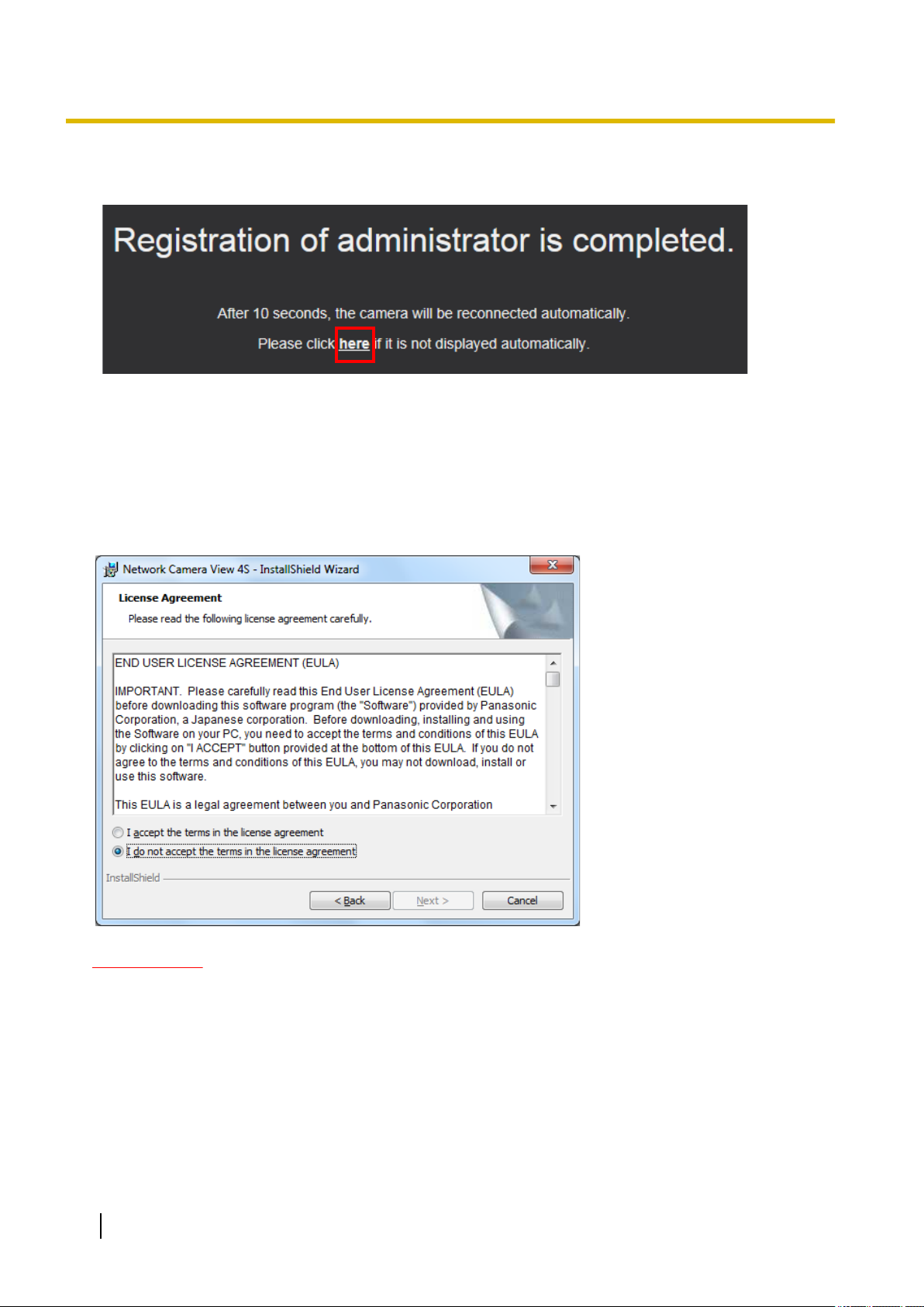
The registration completion screen will be displayed after registering a user name and password of the
administrator. After 10 seconds, the camera will be reconnected automatically. Please click “here” if it is not
displayed automatically.
Operating Instructions 3
Preface
When the camera is reconnected to, an authentication window is displayed. Enter the registered user name
and password to start operation.
Viewer software
In order to display H.265 (or H.264) images, send/receive audio to/from the camera, and play images saved
on the SD memory card, the “Network Camera View 4S” (ActiveX®) viewer software must be installed. This
software can be installed directly from the camera or by selecting the [Install] button next to [Viewer
Software] on the menu of the CD-ROM provided, and then following the on-screen instructions.
IMPORTANT
• The default setting of “Automatic installation” is “On”. Follow the instructions on page 236 when the
message is displayed on the information bar of the browser.
• Depending on the software environment of your PC, it may take time for the message to be displayed
on the information bar of the browser.
• If you display the “Live” page on a PC and click the [Viewer Software] button, the installation screen
for ActiveX, which is required for viewing camera images, is displayed. Follow the on-screen
instructions and install the software. When displayed JPEG images (still images), there is no need to
install ActiveX.
• When the install wizard is displayed again even after completing the installation of the ActiveX, restart
the PC.
4 Operating Instructions

Preface
• The viewer software used on each PC should be licensed individually. The number of installations of
the viewer software from the camera can be checked on the [Upgrade] tab of the “Maintenance” page
(®page 210). Refer to your dealer for the software licensing.
Operating Instructions 5

Table of Contents
Table of Contents
1 Operations ................................................................................................9
1.1 Monitor images on a PC ...................................................................................................9
1.1.1 Monitor images from a single camera ..............................................................................9
1.1.2 About the “Live” page .....................................................................................................12
1.1.3 Monitor images from multiple cameras ..........................................................................17
1.2 Monitor images on a cellular phone/mobile terminal ..................................................20
1.2.1 Monitor images on a cellular phone ...............................................................................20
1.2.2 Monitor images on a mobile terminal (including smartphones) ......................................21
1.3 Record images on the SD memory card manually ......................................................26
1.4 Action at an alarm occurrence .......................................................................................28
1.4.1 Alarm type ......................................................................................................................28
1.4.2 Action at an alarm occurrence ........................................................................................28
1.5 Transmit images onto an FTP server ............................................................................30
1.5.1 Transmit an alarm image at an alarm occurrence (Alarm image transmission) .............30
1.5.2 Transmit images at a designated interval or period (FTP periodic image
transmission) ..................................................................................................................30
1.5.3 Save images on the SD memory card when images fail to transmit using the FTP periodic
image transmission function ...........................................................................................31
1.6 Display the log list ..........................................................................................................32
1.7 Playback of images on the SD memory card ...............................................................36
1.7.1 Playback “JPEG(1)”/“JPEG(2)” images saved to the SD memory card .........................36
1.7.2 Playback “Stream(1)”/“Stream(2)”/“Stream(3)”/“Stream(4)” images saved to the SD
memory card ..................................................................................................................39
2 Settings ...................................................................................................42
2.1 About the network security ............................................................................................42
2.1.1 Equipped security functions ...........................................................................................42
2.2 Display the setup menu from a PC ................................................................................43
2.2.1 How to display the setup menu ......................................................................................43
2.2.2 How to operate the setup menu .....................................................................................44
2.2.3 About the setup menu window .......................................................................................45
2.3 Use Easy Setup [Easy Setup] ........................................................................................47
2.3.1 Configure the Internet settings [Internet] ........................................................................47
2.3.2 Configure an event action [Event action] ........................................................................48
2.3.2.1 Configure the schedule/alarm (event function type setup menu) ................................51
2.3.2.2 Alarm: Configure the terminal and VMD (alarm setup menu) ......................................51
2.3.2.3 Alarm: Configure the alarm function type (Alarm function type setup menu) ..............53
2.3.2.4 Alarm: Configure the details for image transfer or recording conditions ......................54
2.3.2.5 Alarm: Configure the output terminal ...........................................................................56
2.3.2.6 Alarm: configure the mail notifications and mail server ...............................................57
2.3.2.7 Schedule: Configure SD recording or FTP periodic image transmission (schedule
function type setup menu) ...........................................................................................59
2.3.2.8 Schedule: Set SD memory recording (video recording setup menu) ..........................59
2.3.2.9 Schedule: Configure FTP periodic image transmission (FTP periodic image transmission
setup menu) .................................................................................................................61
2.4 Configure the basic settings of the camera [Basic] ....................................................65
2.4.1 Configure the basic settings [Basic] ...............................................................................65
2.4.2 Configure the settings relating to the SD memory card [SD memory card] ....................72
2.4.3 Configure the settings relating to alteration detection [Alteration detection] ..................80
2.4.4 How to configure alteration detection settings ................................................................82
2.4.4.1 Generation of the CRT key (encryption key) ...............................................................82
2.4.4.2 Generation of CSR (Certificate Signing Request) .......................................................83
6 Operating Instructions

Table of Contents
2.4.4.3 Installation of the certificate issued by CA ...................................................................85
2.4.4.4 Configuration of alteration detection ............................................................................86
2.4.5 Access copy images saved on the SD memory card onto the PC [SD memory card
images] ...........................................................................................................................87
2.4.6 Configure the directory of the PC that images will be downloaded to [Log] ...................89
2.5 Configure the settings relating to images and audio [Image/Audio] .........................90
2.5.1 Configure the settings relating to the image capture mode [Image] ...............................90
2.5.2 Configure the settings relating to JPEG images [Image] ................................................91
2.5.3 Configure the settings relating to Stream [Image] ..........................................................93
2.5.4 Configure the settings relating to image adjust, zoom/focus, privacy zone, VIQS, and lens
distortion compensation [Image quality] .........................................................................99
2.5.4.1 Configure the settings relating to image quality (“Image adjust” setup menu) ..........100
2.5.4.2 Set mask areas ..........................................................................................................109
2.5.4.3 Adjust the zoom and focus ........................................................................................112
2.5.4.4 Configure the settings relating to the privacy zone (“Privacy zone” setup
menu) ........................................................................................................................115
2.5.4.5 Configure the VIQS setting ........................................................................................117
2.5.4.6 Configure the VIQS area ...........................................................................................119
2.5.4.7 Configure the settings relating to lens distortion compensation ................................121
2.5.5 Configure the settings relating to audio [Audio] ............................................................122
2.6 Configure the multi-screen settings [Multi-screen] ...................................................125
2.7 Configure the alarm settings [Alarm] ..........................................................................127
2.7.1 Configure the settings relating to the alarm action [Alarm] ...........................................127
2.7.2 Configure the settings relating to the output terminal [Alarm] ......................................129
2.7.3 Change the AUX name [Alarm] ....................................................................................130
2.7.4 Configure the settings relating to the camera action on alarm occurrence
[Alarm] ..........................................................................................................................131
2.7.4.1 Configure settings relating to image quality on alarm action .....................................132
2.7.4.2 Configure settings relating to alarm E-mail notifications ............................................133
2.7.4.3 Configure settings relating to FTP transmissions of alarm images ...........................134
2.7.4.4 Configure settings relating to recording to an SD memory card when an alarm
occurs ........................................................................................................................135
2.7.4.5 Configure settings relating to Panasonic alarm protocol notification when an alarm
occurs ........................................................................................................................136
2.7.4.6 Configure settings relating to HTTP alarm notification when an alarm occurs ..........137
2.7.5 Configure the VMD settings [VMD area] ......................................................................137
2.7.6 Set the VMD areas [VMD area] ....................................................................................139
2.7.7 Configuration of the settings relating to alarm notification [Notification] .......................141
2.7.7.1 Configure the settings relating to Panasonic alarm protocol .....................................142
2.7.7.2 Configure the settings relating to HTTP alarm notification ........................................144
2.8 Configure the settings relating to the authentication [User mng.] ...........................146
2.8.1 Configure the settings relating to the user authentication [User auth.] .........................146
2.8.2 Configure the settings relating to the host authentication [Host auth.] .........................149
2.8.3 Configure IEEE 802.1X [IEEE 802.1X] .........................................................................151
2.8.4 Configure the data encryption settings [Data encryption] .............................................154
2.9 Configuring the network settings [Network] ..............................................................157
2.9.1 Configure the network settings [Network] .....................................................................157
2.9.2 Configure advanced network settings [Advanced] .......................................................161
2.9.2.1 Configure the settings related to sending E-mails .....................................................162
2.9.2.2 Configure the settings related to FTP transmission ...................................................167
2.9.2.3 Configure the settings relating to the NTP server ......................................................170
2.9.2.4 Configure the UPnP settings .....................................................................................172
2.9.2.5 Configure the HTTPS settings ...................................................................................173
2.9.2.6 Configure the settings relating to DDNS ....................................................................175
2.9.2.7 Configure the settings relating to SNMP ...................................................................176
Operating Instructions 7

Table of Contents
2.9.2.8 Configure the QoS settings .......................................................................................177
2.9.3 How to configure HTTPS settings ................................................................................179
2.9.3.1 Select the certificate to use when accessing with HTTPS .........................................180
2.9.3.2 Obtaining the root certificate ......................................................................................180
2.9.3.3 Configuration of HTTPS connections ........................................................................186
2.9.3.4 Generation of the CRT key (SSL encryption key) .....................................................187
2.9.3.5 Generation of CSR (Certificate Signing Request) .....................................................188
2.9.3.6 Installation of the CA certificate .................................................................................189
2.9.4 Access the camera using the HTTPS protocol (for pre-installed certificate) ................190
2.9.4.1 Configuration of the host file ......................................................................................190
2.9.5 Access the camera using the HTTPS protocol (for CA Certification) ...........................195
2.9.6 How to configure the settings relating to DDNS ...........................................................196
2.9.6.1 Configuration of the DDNS service (Example of the “Viewnetcam.com”
service) ......................................................................................................................197
2.9.6.2 When using “Dynamic DNS Update” .........................................................................200
2.9.6.3 When using “Dynamic DNS Update(DHCP)” ............................................................201
2.10 Configure the settings relating to the schedules [Schedule] ...................................202
2.10.1 How to set the schedules .............................................................................................205
2.10.2 How to delete the set schedule ....................................................................................207
2.11 Maintenance of the camera [Maintenance] .................................................................209
2.11.1 Check the system log [System log] ..............................................................................209
2.11.2 Upgrade the firmware [Upgrade] ..................................................................................210
2.11.3 Check the status [Status] .............................................................................................211
2.11.4 Reset the settings/Reboot the camera [Default reset] ..................................................214
2.11.5 Settings data/backing up or restoring logs [Data] .........................................................215
2.12 Display the Panasonic support website [Support] ....................................................217
3 Others ....................................................................................................218
3.1 Using the CD-ROM ........................................................................................................218
3.1.1 About the CD launcher .................................................................................................218
3.1.2 Installing Panasonic “IP Setting Software” ...................................................................219
3.1.3 Installing the manuals ...................................................................................................220
3.1.4 Installing the Viewer software .......................................................................................220
3.1.5 Configure the network settings of the camera using the Panasonic “IP Setting
Software” ......................................................................................................................221
3.2 About the displayed system log ..................................................................................224
3.3 Troubleshooting ............................................................................................................228
3.4 Directory structure of drive B ......................................................................................238
8 Operating Instructions
1 Operations
1.1 Monitor images on a PC
The following are descriptions of how to monitor images from the camera on a PC.
1.1.1 Monitor images from a single camera
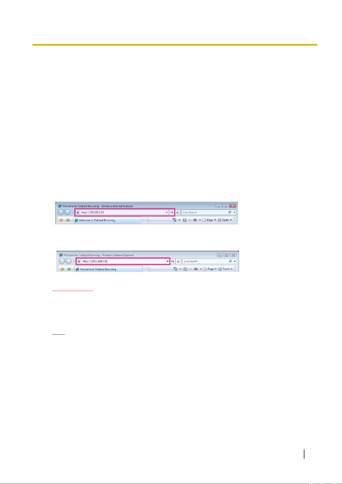
1. Start up the web browser.
2. Enter the IP address designated using the Panasonic “IP Setting Software” in the address box of the
browser.
• Example when entering an IPv4 address: http://URL registered using IPv4 address
http://192.168.0.10/
• Example when entering an IPv6 address: http://[URL registered using IPv6 address]
http://[2001:db8::10]/
<Example of IPv4 access>
1 Operations
<Example of IPv6 access>
IMPORTANT
• When the HTTP port number is changed from “80”, enter “http://IP address of the camera + : (colon)
+ port number” in the address box of the browser. (Example: http://192.168.0.11:8080)
• When the PC is in a local network, configure the proxy server setting of the web browser (under
[Internet Options...] under [Tools] of the menu bar) to bypass the proxy server for the local address.
Note
• Refer to page 190 and page 195 for further information about the case in which “HTTPS” is
selected for “HTTPS” - “Connection” on the [Advanced] tab of the “Network” page (®page 157).
Operating Instructions 9
1 Operations
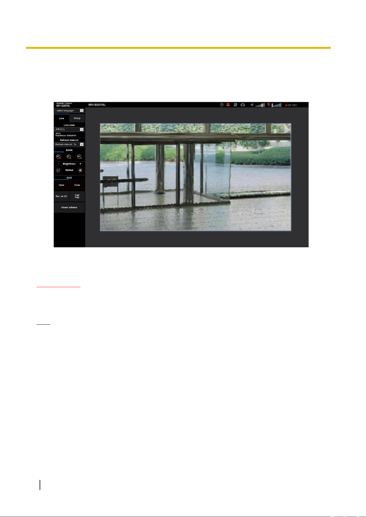
3. Press the [Enter] key on the keyboard.
→ The “Live” page will be displayed. Refer to page 12 for further information about the “Live” page.
When “On” is selected for “User auth.”, the authentication window will be displayed before displaying live
images for the user name and password entries.
IMPORTANT
• It is recommended to change the password periodically.
• When displaying multiple H.265 (or H.264) images on a PC, images may not be displayed depending
on the performance of the PC.
Note
• The maximum number of concurrent access user is 14 including users who is receiving H.265 (or H.
264) images and users who are receiving JPEG images. Depending on the set values for “Bandwidth
control(bit rate)” and “Max bit rate (per client)*”, the maximum concurrent access number may be 14
or less users. When 14 users are concurrently accessing, the access limit message will be displayed
for users who subsequently attempt to access. When “Multicast” is selected for “Transmission type” of
“Stream”, only the first user who accessed to monitor H.265 (or H.264) images will be included in the
maximum number. The second and subsequent users who are monitoring H.265 (or H.264) images
will not be included in the maximum number.
• If you set the “Stream transmission” (®page 93) to “On”, an H.265 (or H.264) image will be displayed
based on the settings of the “Stream encoding format”. If you set the “Stream transmission” (®page
93) to “Off”, a JPEG image will be displayed. A JPEG image can be displayed even if the “Stream
transmission” is set to “On”, but in that case, the transmission interval of the JPEG image will be
restricted.
• The refresh interval may become longer depending on a network environment, PC performance,
photographic subject, access traffic, etc.
<Refresh interval of JPEG images>
When “On” is selected for “Stream transmission”
10 Operating Instructions

1 Operations
max. 1 fps (at 3840x2160), max. 2 fps (at 2560x1440), max. 5 fps (at 1920x1080, 1280x720, 640x360,
320x180)
When “Off” is selected for “Stream transmission”
16:9 (15 fps) mode: max. 15 fps
16:9 (30 fps) mode: max. 30 fps
Operating Instructions 11
A
C
E
J
K
L
D
G
F
U
H
I
NO P Q R S T
M
B
1 Operations
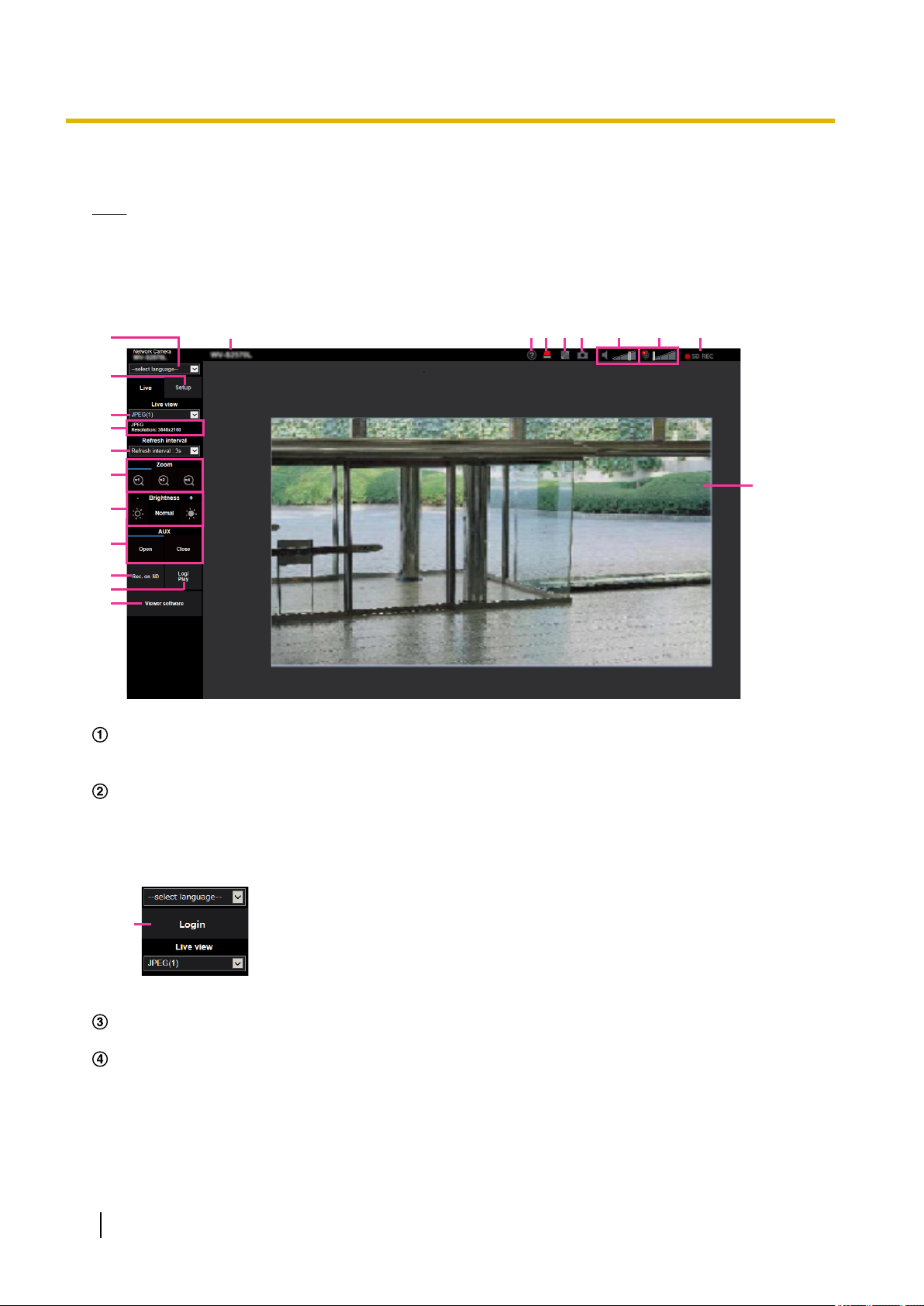
1.1.2 About the “Live” page
Note
• The buttons and setting items displayed on the “Live” page can be changed depending on the user
rights of the accessing user. You can set the user right settings from “User auth.” under “User mng.”.
(®page 146)
[select language] pull-down-menu
The camera’s display language can be selected. The default language can be set in the [Menu language]
in the [Basic] settings. (®page 65)
[Login] button
This button is displayed when “User auth.” is “On” and a person other than the administrator logs in, or
when “User auth.” is “Off” and “Guest User” is set to “Use”. (®page 146)
Even in the above case, the [Login] button will not be displayed if “Host auth.” is set to “On”, and the camera
browser is opened from a host with administrator rights.
If login fails, close all the browsers, open the “Live” page and login once again.
[Setup] button
*1
Displays the setup menu.
[Live view] pull-down menu
You can select and switch to the image to be displayed in the main area from the following:
Stream(1)/Stream(2)/Stream(3)/Stream(4)/JPEG(1)/JPEG(2)/Multi-screen
The image in the main area is displayed based on the contents set in Stream(1) – (4) (®page 93),
JPEG(1) – (2) (®page 91), or Multi-screen (®page 125).
12 Operating Instructions

1 Operations
Also the first stream displayed when you accessed the camera can be set from “Initial display stream” of
the [Image] tab. For “Multi-screen”, you can set the “Initial display” in the [Multi-screen] tab.
Note
• When the image capture size is larger than “1280´720”, the image may become smaller than the
actual size depending on the window size of the web browser.
Stream information display
Displays the setup for stream encoding format, image capture size, bit rate, and frame rate for the live view
of a stream.
Note
• Displays the values set in the stream. The actual bit rate and frame rate vary depending on the
network environment and the used PC.
[Refresh interval] pull-down menu
This pull-down menu will be displayed only when a JPEG image is displayed. Use it to select the display
method of the JPEG image.
• MJPEG: Uses viewer software to display JPEG images successively as MJPEG (Motion JPEG). Not
available if the viewer software is not installed.
• Refresh interval : 1s/Refresh interval : 3s/Refresh interval : 5s/Refresh interval : 10s/Refresh
interval : 30s/Refresh interval : 60s: Refreshes JPEG format (still images) images at the specified
interval.
Note
• Depending on the network environment or the PC used, JPEG format (still images) images may
not be refreshed at the specified interval.
• The [Refresh interval] pull-down on the “Live” page is not displayed for JPEG images with data
encryption set to “On”.
[Zoom] buttons
Images will be zoomed in on with the electronic zoom by the viewer software “Network Camera View
4S”.
• [x1] button: The images in the main area will be displayed at x1.
• [x2] button: The images in the main area will be displayed at x2.
• [x4] button: The images in the main area will be displayed at x4.
[Brightness] buttons
The brightness is adjustable from 0 to 255. Click the
button to make the image darker. If you click the [Normal] button, the display will be reset to default.
[AUX] button
These buttons will be displayed only when “Terminal 3” of “Alarm” is set to “AUX output” on the setup menu.
(®page 51)
*2
button to make the image brighter, or click the
• [Open] button: The status of the AUX connector will be open.
• [Close] button: The status of the AUX connector will be closed.
Note
• The names of “AUX”, “Open” and “Close” can be changed. (®page 130)
[Rec. on SD] button
The [Rec. on SD] button will be displayed only when “Manual” is selected for “Save trigger” on the [SD
memory card] tab. (®page 76)
Click this button to manually record images on the SD memory card. Refer to page 26 for descriptions
of how to manually record images on the SD memory card.
[Log/Play] button
When the [Log/Play] button is clicked, the log list will be displayed and images saved on the SD memory
card can be played.
*2
Operating Instructions 13

1 Operations
Refer to page 32 for further information about the log list and for how to play images on the SD memory
card.
[Viewer software] button
Starts installation of the viewer software for display. This button will not be available if the viewer software
is already installed on the PC, or if the “Automatic installation” of the [Viewer software
(nwcv4Ssetup.exe)] in the [Basic] tab is set to “Off”. (®page 69)
Camera title
The camera title entered for “Camera title” on the [Basic] tab will be displayed. (®page 66)
Support button
When this button is clicked, the support site below will be displayed in a newly opened window. This website
contains technical information, FAQ, and other information.
https://security.panasonic.com/support/
Alarm occurrence indication button
When an alarm occurs, the display flashes. When this button is clicked, the output terminal will be reset
and this button will disappear. (®page 28)
Note
Full screen button
Images will be displayed on a full screen. If the full screen button is clicked once when the image displayed
in the main area is smaller than the main area, the image is displayed corresponding to its image capture
size. If the full screen button is clicked once when images are displayed corresponding to their image
capture sizes, images are displayed in full screen. To return to the “Live” page when displaying an image
in full screen, press the [Esc] key.
Snap shot button
Click this button to take a picture (a still picture). The picture will be displayed on a newly opened window.
When right-clicking on the displayed image, the pop-up menu will be displayed. It is possible to save the
image on the PC by selecting “Save” from the displayed pop-up menu.
When “Print” is selected, printer output is enabled.
*2
• Since the blinking of the alarm occurrence indication button is not coupled to recording images to
the SD memory card, forwarding E-mails, or other operations, check the settings of each operation
separately.
Note
• If the viewer software is not installed, “Save” and “Print” will not be displayed in the pop-up menu.
• The following settings may be required.
Open Internet Explorer, click [Tools] ® [Internet Options] ® [Security] ® [Trusted Sites] ®
[Sites]. Register the camera address on [Website] of the displayed trusted windows. After
registration, close the web browser, and then access the camera again.
• When it takes longer than the specified period to obtain the snap shot picture due to the network
environment, the snap shot picture may not be displayed.
• If the image capture size specified for JPEG cannot be obtained, JPEG images are displayed with
the image capture size that could be obtained.
Therefore, when JPEG images obtained with snap shot are displayed on a PC, the displayed image
size may differ from the captured sized.
• If the encryption setting for JPEG(1) or JPEG(2) is “On”, the Snap shot button is not displayed.
Mic input button
Turns on/off the audio reception (hear audio from the camera on a PC). This button will be displayed only
when “Mic input”, “Interactive(Full-duplex)”, or “Interactive(Half-duplex)” is selected for “Audio transmission
mode” on the setup menu. (®page 122)
When the audio reception is turned off, the button will turn into the button and audio from the camera
will not be heard.
Audio volume can be adjusted (Low/ Middle/ High) by moving the volume cursor .
14 Operating Instructions

1 Operations
Note
• When “Audio volume control mode” is set to “Adjust Mic input” in the setup menu, the volume cursor
is not displayed when using “Audio recording”.
• When the camera is restarted, the adjusted volume level (for the reception) will return to the level
that had been set on the [Audio] tab on the setup menu. (®page 122)
• Actual volume level will change in three steps even though the volume cursor can be adjusted
minutely.
• If multiple camera browsers are open at the same time on the same computer, audio cannot be
heard from the camera browsers that were opened later. Please only access 1 camera at a time.
Audio output button
Turns on/off the audio transmission (play audio from the PC on the unit speaker). This button will be
displayed only when “Audio output”, “Interactive(Full-duplex)” or “Interactive(Half-duplex)” is selected for
“Audio transmission mode” on the setup menu. (®page 122)
The button will blink during the audio transmission. When the audio transmission is turned off, the button
display will switch to the
Audio output volume can be adjusted (Low/Middle/High) by moving the volume cursor .
Note
, and audio from the PC will not be heard.
• When a user is using the audio transmission function with “Interactive(Half-duplex)” selected, the
receiver button and the transmission button will be inoperable for the other users. When
“Interactive(Full-duplex)” is selected, the transmission button is inoperable for other users.
• The maximum duration of a single audio output is the audio output duration set in the [Audio] tab
on the “Image/Audio” page. Audio output stops when the specified audio output duration has
passed. To turn the audio transmission function on, click the [Audio output] button again.
• When the camera is restarted, the adjusted volume level (for both the audio transmission and
reception) will return to the level that had been set on the [Audio] tab on the “Image/Audio” page.
(®page 122)
• Actual volume level will change in three steps even though the volume cursor can be adjusted
minutely.
SD recording status indicator
The status of the SD recording can be checked with this indicator.
When the SD recording starts, the SD recording status indicator will light red. It will go off when the SD
recording stops.
This indicator will be displayed when “Manual” or “Schedule” is selected for “Save trigger” on the setup
menu. (®page 72)
Main area
Images from the camera will be displayed in this area.
The current time and date will be displayed according to the settings configured for “Time display format”
and “Date/time display format”. (®page 65)
In addition, when being adjusted, the status of brightness (®page 68) will be displayed as well as the
characters configured for “Camera title on screen” (®page 67). The number of lines for the display is 2.
A zoom operation can be performed using the mouse wheel.
When clicking a desired point while displaying live images at x2 or x4 in the main area, the camera will
move to locate the clicked point at the center of the main area.
Note
• When the camera is operated by a user with a low access level, images displayed on the screen
may be changed temporarily. This does not affect operation of the camera.
• Depending on the PC in use, screen tearing* may occur when the shooting scene drastically
changes due to the GDI restrictions of the OS.
Operating Instructions 15

1 Operations
*1
Only operable by users whose access level is “1. Administrator”.
*2
Only operable by users whose access level is “1. Administrator” or “2. Camera control” when “On” is selected for “User
auth.” (®page 146)
*A phenomenon in which portions of the screen are displayed out of alignment.
16 Operating Instructions

1 Operations
1.1.3 Monitor images from multiple cameras
Images from multiple cameras can be displayed on a multi-screen. Images from 4, 9, and up to 16 cameras
can be displayed simultaneously. To display images on a multi-screen, it is necessary to register cameras in
advance. 4 cameras can be registered as a group and up to 4 groups (16 cameras) can be registered.
(®page 125)
IMPORTANT
• When video is displayed in 4 screens and 9 screens, the video and audio may cut out because the
transmission volume of other cameras is large. In such cases, the setting of the registered cameras
needs to be changed to reduce the transmission volume.
Example of setup to reduce the transmission volume:
– Set the video transmission format to “H.265” or “H.264”.
– Set the “Transmission priority” (®page 94) of the stream to “Best effort”.
• To enable the audio for multi-screen, the audio must be enabled for the camera.
• When 16 screens are used for the display, only still images (JPEG) can be refreshed.
Note
• Multi-screen can be used to display JPEG images, and H.265 (or H.264) images. If other cameras
support audio, audio is also output.
• Adjust the volume when multi-screen is displayed.
• For further information about “Network Camera Recorder with Viewer Software Lite”, which is suited
to viewing images from several cameras, refer to our website
(https://security.panasonic.com/support/info/ <Control No.: C0301>).
• When you have registered a camera with the authentication function enabled, enter the user name and
password of the “Administrator” for the registered camera in the “Authentication dialog”.
Refer to the Panasonic support website below for information about the terms and conditions for use
of multi-screen.
https://security.panasonic.com/support/info/ <Control No.: C0302>
Operating Instructions 17
A
B
F
C
D
E
G
1 Operations
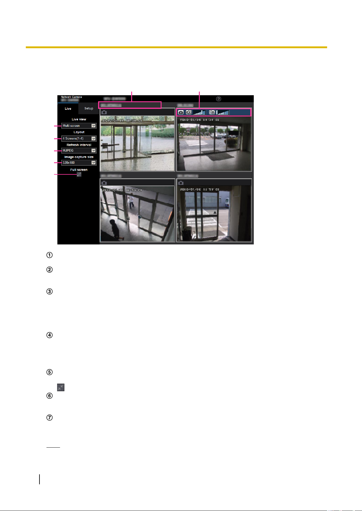
1. From the “Live view” pull-down menu in the “Live” page, select “Multi-screen”.
→ Images from the registered cameras will be displayed on a selected multi-screen (screen can be split
up to 16 areas). The following are instructions when displaying on a 4-split screen.
“Live view” pull-down menu
Select the image displayed in the main area.
[Layout] pull-down menu
Select from the pull-down menu to display images from cameras in multi-screens of 4 to 9 or even 16
screens.
[Refresh interval] pull-down menu
Select from the pull-down menu and switch between video (H.265/H.264/MJPEG) and still images
(JPEG).
For still images (JPEG), select the refresh interval (Refresh interval : 1s/Refresh interval : 3s/Refresh
interval : 5s/Refresh interval : 10s/Refresh interval : 30s/Refresh interval : 60s) for camera images.
When the 16 screen layout is used, Refresh interval : 1s cannot be selected.
[Image capture size] pull-down menu
Select the image capture size from the pull-down menu to change it.
When you select “4 Screens” in the [Layout] pull-down menu, the image capture size of the camera
changes.
• Switching between 320x180 (default) and 640x360
Full screen display
If you press the full screen button, the display of the camera image will be maximized. If you click the
(reset) button in the full screen display, the display size will be reset to original size.
Camera title
If you click the camera title, live images from the corresponding camera will be displayed on the
“Live” page of the newly opened window.
Camera control bar
Can be used to get snap shot of JPEG images or to adjust the PC mic input/output volume (mic input
or audio output).
Note
• The frame rate may drop depending on the network environment and number of accessing users.
18 Operating Instructions

1 Operations
• If the image capture size specified for JPEG cannot be obtained, a JPEG image with an image
capture size that could be obtained is displayed. Therefore, when JPEG images obtained with snap
shot are displayed on a PC, the displayed image size may differ from the captured sized.
• When the live image is displayed in the still image (JPEG), the “Save” and “Print” pop-up menus
will not be displayed at the time of obtaining snap shot of the JPEG image.
• When in full screen display, click¢ering and zoom are not available.
• When a video (H.265/ H.264/ MJPEG) is selected from the “Refresh interval” pull-down menu, a
different video from the setting may be displayed subject to the connected camera settings.
Operating Instructions 19

A
B
C
1 Operations
1.2 Monitor images on a cellular phone/mobile terminal
1.2.1 Monitor images on a cellular phone
It is possible to connect to the camera using a cellular phone via the Internet and monitor images (JPEG only)
from the camera on the screen of the cellular phone. It is also possible to refresh images to display the latest
image.
IMPORTANT
• When the authentication window is displayed, enter the user name and password.
To enhance the security, it is recommended to change the password periodically. (®page 146)
• If the cellular phone in use is not compatible with UTF-8 encode, it is impossible to display the screen
correctly.
• When “640x360” or “320x180” is not selected for either one of “JPEG(1)” or “JPEG(2)” of [JPEG] on
the [Image] tab, images cannot be viewed from cellular phones.
• Audio is not supported for cellular phones.
Note
• It is necessary to configure the network settings of the cellular phone in advance to connect to the
Internet and monitor images from the camera. (®page 157)
• When “Auto” is selected for “Menu language”, the screen is displayed in English. If you want the screen
to be displayed in Japanese or Chinese, select “Japanese” or “Chinese” for “Menu language”.
(®page 65)
For further information about compatible devices, refer to our website
(https://security.panasonic.com/support/info/ <Control No.: C0108>).
1. Access to “http://IP address/mobile”
cellular phone.
*1
or “http://Host name registered in the DDNS server/mobile” using a
→ Images from the camera will be displayed.
20 Operating Instructions

1 Operations
Refresh control
Press the dial key “5” or the [Manual Refresh] button to refresh the camera images.
Press the [Auto Refresh] button to refresh the images from the camera in 5-second intervals.
When the dial key “5” or the [Manual Refresh] button is pressed again, the refresh mode of the camera
will return to manual refresh.
IMPORTANT
• Transmission will be periodically performed when “Auto Refresh” is selected for the camera
image. Confirm the contract plan of the cellular phone in use before using this function.
• Depending on the cellular phone in use, “Auto Refresh” may be unavailable.
Resolution control
Changes the image capture size by pressing the dial key “0”. This function is only displayed when
“320x180” is selected for “Image capture size” of JPEG(1) in the setup menu.
• Changes the image capture size between 320x180 and 640x360.
AUX control
Controls the AUX terminal. These buttons will be displayed only when “AUX output” is selected for
“Terminal 3” on the setup menu. (®page 51)
Note
• Some cellular phones cannot change the image capture size even when resolution is changed by
resolution control.
• When the HTTP port number is changed from “80”, enter “http://IP address: (colon) + port number/
mobile”*1 in the address box of the browser. When using the DDNS function, access to “http://Host
name registered in the DDNS server: (colon) + port number/mobile”.
• When “HTTPS” is selected for “HTTPS” - “Connection” on the [Advanced] tab of the “Network” page,
enter as follows.
“https://IP address: (colon) + port number/mobile” or “https://Host name registered in the DDNS server:
(colon) + port number/mobile”
• When the authentication window is displayed, enter the user name of an administrator or user and
password. Depending on the cellular phone in use, password entry may be required each time the
screen is switched.
• Depending on the cellular phone in use, larger size images may not be displayed. In this case, selecting
a setting close to the lowest quality setting for “Image quality setting” of “JPEG” (®page 91) may
sometimes solve this problem.
• Depending on the cellular phone in use or its contract plan, it may be impossible to access.
• The operations menu displayed on the mobile telephone screen may not be displayed depending on
the user rights and access level of the accessing user. To display the operations menu, it is necessary
to set the user rights and access level (“User auth.” in “User mng.”). (®page 146)
*1
IP address is the global WAN IP address of the router that can be accessed via the Internet.
1.2.2 Monitor images on a mobile terminal (including
smartphones)
It is possible to connect to the camera using a mobile terminal via the Internet and monitor images (MJPEG
or JPEG) from the camera on the screen of the mobile terminal. It is also possible to refresh images to display
the latest image.
The compatible mobile terminals are shown as follows. (As of April, 2019)
– iPad, iPhone (iOS 4.2.1 or later)
– Android™ mobile terminals
Operating Instructions 21
C
B
A
1 Operations
When an Android terminal is used, an MJPEG format image is displayed by the Firefox® browser, and a JPEG
format image is displayed by the standard browser.
For further information about compatible devices, refer to our website
(https://security.panasonic.com/support/info/ <Control No.: C0108>)
IMPORTANT
• When the authentication window is displayed, enter the user name and password.
To enhance the security, it is recommended to change the password periodically. (®page 146)
Note
• It is necessary to configure the network settings of the mobile terminal in advance to connect to the
Internet and monitor images from the camera. (®page 157)
1. Access to “http://IP address/cam”
mobile terminal.
→ Images from the camera will be displayed.
*1
or “http://Host name registered in the DDNS server/cam”*2 using a
Live images area
Displays images from the camera.
Operation buttons area
When functions are selected in the function selection area C, buttons to operate those functions are
displayed.
Function selection area
When functions that can be operated are selected, operation buttons are displayed in the operation
buttons area B.
Note
• The operations button displayed on the mobile terminal screen may not be available depending on
the user rights and access level of the accessing user. To display the operations button, it is
necessary to set the user rights and access level (“User auth.” in “User mng.”). (®page 146)
22 Operating Instructions
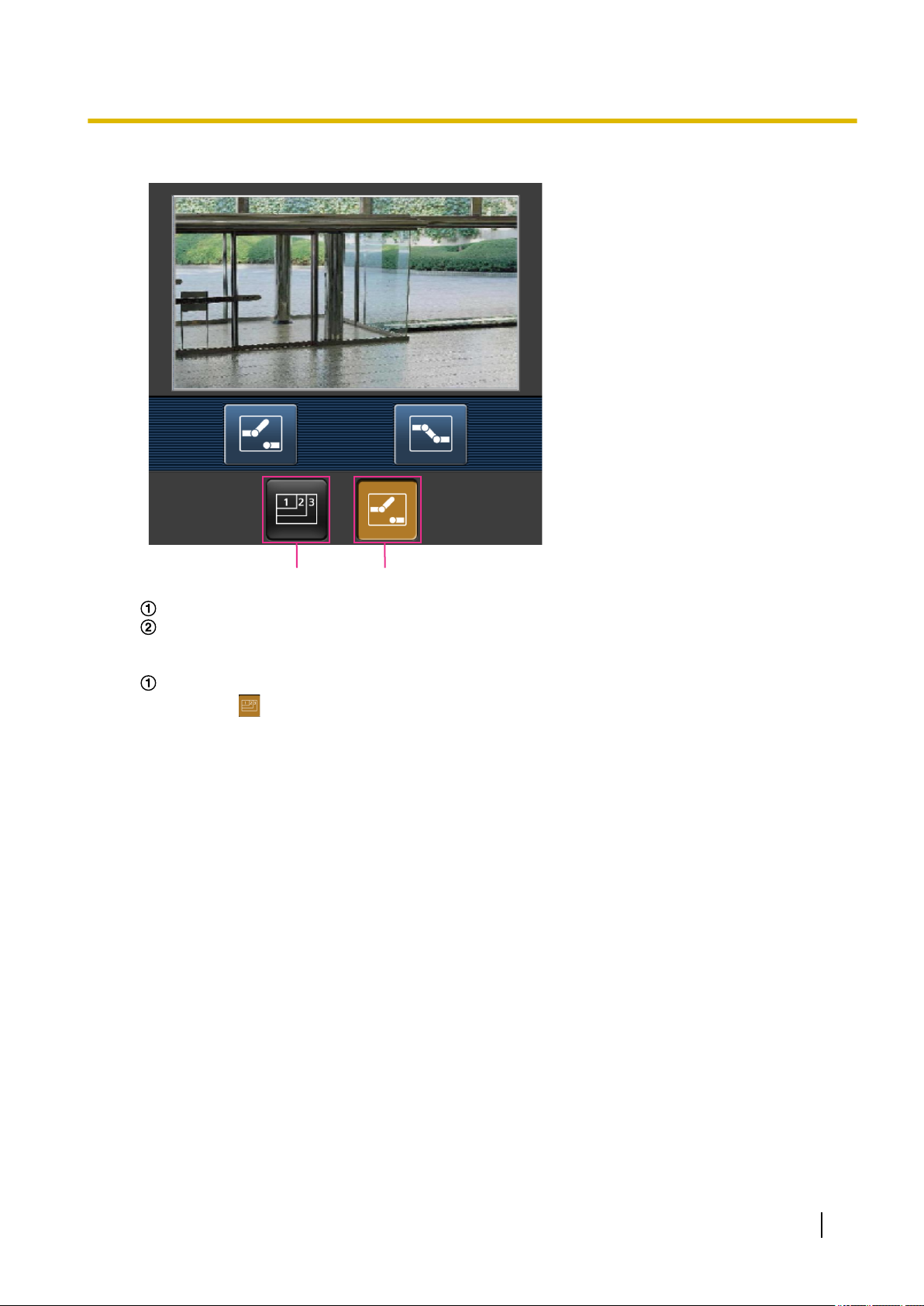
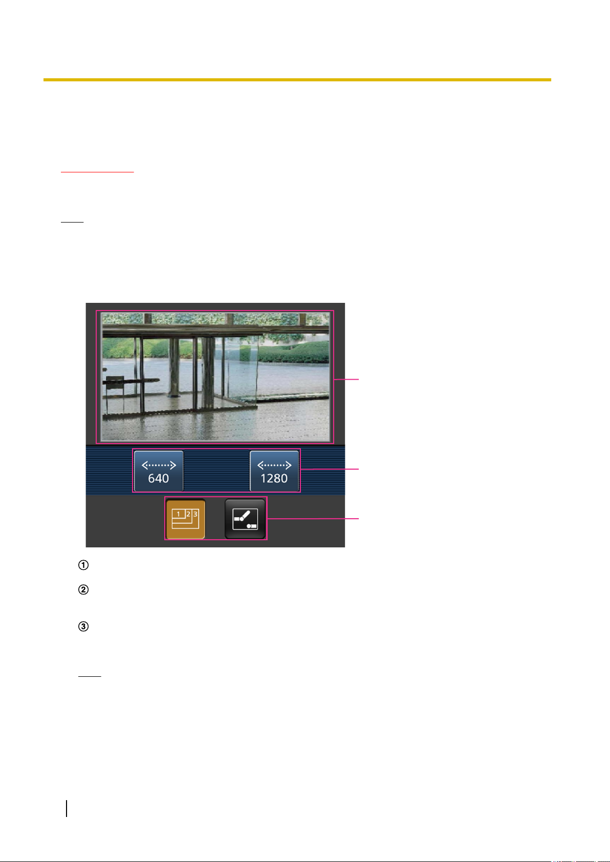
2. Click the button of the function that you want to operate.
A B
1 Operations
Resolution control
AUX control
Each function is explained below.
Resolution control
Press the
button to display the buttons used to select the resolution on the screen.
The resolution can be changed by selecting a resolution setting from the buttons.
Operating Instructions 23
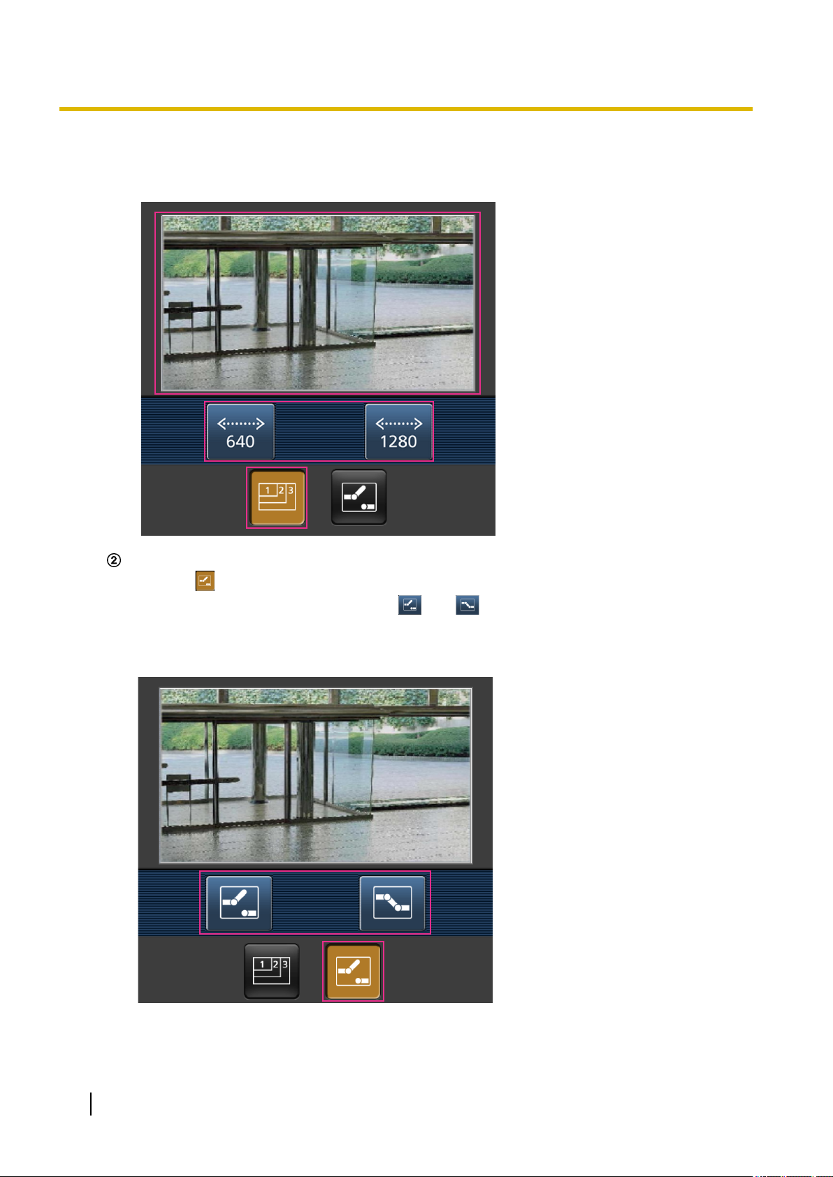
1 Operations
Images are displayed in the image capture size selected in “JPEG(1)” or “JPEG(2)” of [JPEG] on the
[Image] tab. However, the images of the image capture size of “3840´2160” and “2560´1440” cannot
be displayed.
AUX control
Press the
output terminals can be controlled with the
button to display the buttons used to operate the AUX output on the screen. The AUX
and buttons.
This function is only displayed when [Terminal 3] is set to [AUX output] on the settings menu.
(®page 127)
24 Operating Instructions

1 Operations
Note
• You can change the image size displayed on the mobile terminal by accessing the following addresses.
– Large display: http://IP address/cam/dl
– Medium display: http://IP address/cam/dm
– Small display: http://IP address/cam/ds
• When the resolution is changed by the resolution control, the displayed resolution changes but the
image size remains the same.
• When the HTTP port number is changed from “80”, enter “http://IP address: (colon) + port number/
cam”*1 in the address box of the browser. When using the DDNS function, access to “http://Host name
registered in the DDNS server: (colon) + port number/cam”*2.
• When “HTTPS” is selected for “HTTPS” - “Connection” on the [Advanced] tab of the “Network” page,
enter as follows.
“https://IP address: (colon) + port number/cam” or “https://Host name registered in the DDNS server:
(colon) + port number/cam”
• When the authentication window is displayed, enter the user name of an administrator or user and
password. Depending on the mobile terminal in use, password entry may be required each time the
screen is switched.
• It is impossible to send and receive audio using a mobile terminal.
• Depending on the mobile terminal in use, larger size images may not be displayed. In this case,
selecting a setting close to the lowest quality setting for “Image quality setting” of “JPEG” (®page
91) may sometimes solve this problem.
• Depending on the mobile terminal in use or its contract plan, it may be impossible to access.
*1
IP address is the global WAN IP address of the router that can be accessed via the Internet. However, when accessing the same
LAN as the camera with a wireless compatible mobile terminal, the IP address is the local IP address.
*2
Only when accessing the camera via the Internet.
Operating Instructions 25
1 Operations
1.3 Record images on the SD memory card manually
Images displayed on the “Live” page can be recorded on the SD memory card manually. This button is operable
only when “Manual” is selected for “Save trigger” on the [SD memory card] tab on the “Basic” page of the setup
menu. (®page 76)
It is possible to select “JPEG(1)”, “JPEG(2)”, “Stream(1)”, “Stream(2)”, “Stream(3)”, or “Stream(4)” on
“Recording format” of the setup menu. (®page 75) When “JPEG(1)” or “JPEG(2)” is selected for “Recording
format”, still image data are recorded. When “Stream(1)”, “Stream(2)”, “Stream(3)”, or “Stream(4)” is selected,
video data are recorded.
Images recorded on the SD memory card can be copied onto the PC. (®page 87)
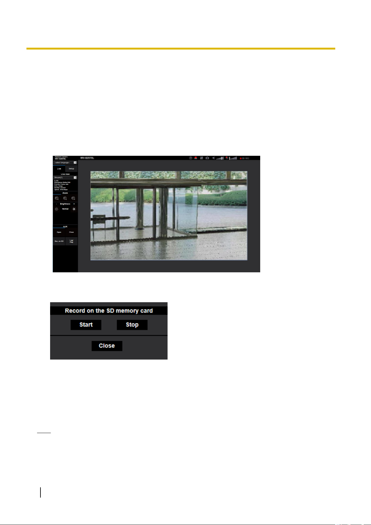
1. Display the “Live” page. (®page 9)
2. Click the [Rec. on SD] button.
→ The SD recording window will open.
3. Click the [Start] button to start recording images on the SD memory card. The SD recording status indicator
will light red (®page 12) while images are being recorded on the SD memory card.
The image saving interval can be configured on the [SD memory card] tab of the “Basic” page.
(®page 72)
4. Click the [Stop] button to stop saving images on the SD memory card.
® The SD recording status indicator will turn off.
5. Click the [Close] button to close the window.
Note
• Image data saved on Drive B can be obtained by executing “Access img.” on the [SD memory card]
tab and logging in from the user authentication window (®page 87).
The destination to save image data is a fixed directory on Drive B (®page 238).
26 Operating Instructions

1 Operations
• When the [Start] button is clicked immediately after the [Stop] button is clicked, saving of images may
not start. In this case, click the [Start] button again.
Operating Instructions 27

1 Operations
1.4 Action at an alarm occurrence
The alarm action (camera action at an alarm occurrence) will be performed when the following alarms occur.
1.4.1 Alarm type
• Terminal alarm: When connecting an alarm device such as a sensor to the alarm input terminal of the
camera, the alarm action will be performed when the connected alarm device is activated.
• VMD alarm: When motion is detected in the set VMD area, the alarm action will be performed.
*VMD stands for “Video Motion Detection”.
• Command alarm: When a Panasonic alarm protocol is received from the connected device via a network,
the alarm action will be performed.
1.4.2 Action at an alarm occurrence
Display the alarm occurrence indication button on the “Live” page
The alarm occurrence indication button will be displayed on the “Live” page at an alarm occurrence.
(®page 12)
IMPORTANT
• When “Polling(30s)” is selected for “Status update mode” (®page 65), the Alarm occurrence
indication button will be refreshed in 30-second intervals. For this reason, it may take a maximum of
30 seconds until the alarm occurrence indication button is displayed on the “Live” page at an alarm
occurrence.
Notify of alarm occurrences to the device connected to the output terminal
It is possible to output signals from the output terminal of the camera and sound the buzzer when an alarm
occurs. The settings for the alarm output can be configured in the [Alarm] tab of the “Alarm” page.
(®page 129)
Save images on the SD memory card
When an alarm occurs, images (JPEG/H.265/H.264) will be saved on the SD memory card. The settings to
save images on the SD memory card can be configured on the [SD memory card] tab (®page 72) of the
“Basic” page and the [Alarm] tab of the “Alarm” page. (®page 131)
Transmit an image onto a server automatically
An alarm image can be transmitted at an alarm occurrence to the server designated in advance. The settings
required to transmit an alarm image to a server can be configured in the “Alarm image” section on the
[Alarm] tab of the “Alarm” page (®page 131) and the [Advanced] tab of the “Network” page (®page 167).
Notify of alarm occurrences by E-mail
Alarm E-mail (alarm occurrence notification) can be sent at an alarm occurrence to the E-mail addresses
registered in advance. Up to 4 addresses can be registered as recipients of the alarm E-mail. An alarm image
(still picture) can be sent with the alarm E-mail as an attached file. The settings for alarm E-mail can be
28 Operating Instructions

1 Operations
configured in the “Alarm E-mail notification” section on the [Alarm] tab of the “Alarm” page (®page 131) and
the [Advanced] tab of the “Network” page (®page 162).
Notify of alarm occurrences to the designated addresses (Panasonic alarm
protocol notification)
This function is available only when a Panasonic device, such as the network disk recorder, is connected to
the system. When “On” is selected for “Panasonic alarm protocol”, the connected Panasonic device will be
notified that the camera is in the alarm state. The settings for Panasonic alarm protocol can be configured in
the “Panasonic alarm protocol notification” section of the [Notification] tab of the “Alarm” page. (®page 142)
Notify of alarm occurrences to the designated HTTP server (HTTP alarm
notification)
Alarm occurrence notifications can be sent at an alarm occurrence to the HTTP servers registered in advance.
Up to 5 HTTP servers can be registered as recipients of alarm notifications. The URL sent to HTTP servers
with alarm notifications can be specified. The settings for HTTP alarm notification can be configured on the
[Notification] tab of the “Alarm” page. (®page 144)
Operating Instructions 29

1 Operations
1.5 Transmit images onto an FTP server
Images can be transmitted to an FTP server. By configuring the following settings, transmission of images
captured at an alarm occurrence or captured at a designated interval to an FTP server will become available.
IMPORTANT
• When using this function, set the user name and the password to access the FTP server to restrict
users who can log into the FTP server.
1.5.1 Transmit an alarm image at an alarm occurrence (Alarm image transmission)
An alarm image can be transmitted at an alarm occurrence to the FTP server. To transmit alarm images to an
FTP server, it is necessary to configure the settings in advance.
FTP server settings and settings relating to alarm image transmission can be configured in the “FTP” section
of the [Advanced] tab of the “Network” page. (®page 167) Settings can also be configured from the “Alarm
image FTP transmission” settings of “Camera action on alarm” on the [Alarm] tab of the “Alarm” page.
(®page 131)
Note
• Depending on the network traffic, the number of the transmitted images may not reach the set number
of images to be transmitted.
• Alarm images failed to be transmitted to the FTP server at an alarm occurrence will not be saved on
the SD memory card. However, images that fail to be transmitted with the FTP periodic image
transmission will be saved.
When “On” is selected for both the alarm image transmission function and the FTP periodic image
transmission function, the alarm image transmission function will be given priority over the FTP periodic
image transmission function. Also, when “On” is selected for the “FTP transmission retry” FTP setting
(®page 168), alarm images will be retransmitted if there is an FTP transmission failure. Therefore, if
there is continuous retransmission due to network problems or other factors, periodic transmission will
not be performed and images that fail to be transmitted with the FTP periodic image transmission will
not be saved to an SD memory card.
1.5.2 Transmit images at a designated interval or period (FTP periodic image transmission)
Images can be transmitted at a designated interval or period. To transmit images at a designated interval or
period, it is necessary to configure the settings in advance.
FTP server settings and settings relating to FTP periodic transmission image transmission can be configured
in the “FTP” section of the [Advanced] tab of the “Network” page. (®page 167)
When using FTP periodic image transmission, it is necessary to configure the schedule settings of FTP periodic
image transmission on the [Schedule] tab of the “Schedule” page.
Configure the schedule settings of the FTP periodic image transmission on the “Schedule” page.
(®page 205)
Note
• Depending on the line speed or the traffic, images may not be transmitted at the designated interval.
• When “On” is selected for both the alarm image transmission function and the FTP periodic image
transmission function, the alarm image transmission function will be given priority over the FTP periodic
30 Operating Instructions
 Loading...