

Page 1
Camera Controller
WV-RM70
Before attempting to connect or operate this product,
please read these instructions completely.
Page 2

CAUTION
RISK OF ELECTRIC SHOCK
DO NOT OPEN
CAUTION:
TO REDUCE THE RISK OF ELECTRIC SHOCK, DO
NOT REMOVE COVER (OR BACK). NO USER SERVICEABLE PARTS INSIDE.
REFER SERVICING TO QUALIFIED SERVICE PERSONNEL.
The lightning flash with arrowhead
symbol, within an equilateral triangle, is
intended to alert the user to the pres-
CAUTION:
Before attempting to connect or operate this product, please read the label on the bottom.
Warning:
This equipment generates and uses radio frequency energy
and if not installed and used properly, i.e., in strict accordance with the instruction manual, may cause harmful
interference to radio communications. It has been tested
and found to comply with the limits for a Class A computing
device pursuant to Subpart J of Part 15 of FCC Rules,
which are designed to provide reasonable protection
against such interference when operated in a commercial
environment.
ence of uninsulated "dangerous voltage" within the product's enclosure that
SA 1965
may be of sufficient magnitude to constitute a risk of electric shock to persons.
The exclamation point within an equilateral triangle is intended to alert the
The serial number of this product may be found on the bottom of the unit.
You should note the serial number of this unit in the space
provided and retain this book as a permanent record of your
purchase to aid identification in the event of theft.
user to the presence of important operating and maintenance (servicing)
instructions in the literature accompanying the appliance.
SA 1966
WARNING:
TO PREVENT FIRE OR SHOCK HAZARD, DO NOT EXPOSE THIS APPLIANCE TO RAIN OR MOISTURE.
Model No.
Serial No.
For U.S.A
Page 3

CONTENTS
PREFACE ...................................................................................................................................................................... 2
FEATURES .................................................................................................................................................................... 2
PRECAUTIONS ............................................................................................................................................................. 3
MAJOR OPERATING CONTROLS AND THEIR FUNCTIONS ....................................................................................... 4
CONNECTIONS ............................................................................................................................................................ 7
OPERATING PROCEDURE ........................................................................................................................................... 13
SPECIFICATIONS ......................................................................................................................................................... 32
-1-
Page 4

PREFACE
FEATURES
The WV-RM70 Camera Controller, when combined with
the optional WV-CP610 and WV-BP510 series CCTV
Camera, enables remote control of camera settings.
Also it is available to receive the alarm (motion detector) signal multiplexed with the video signal from the
WV-CP610 and WV-BP510 series camera.
The WV-RM70 Camera Controller enables remote control of the following functions:
• Remote control of camera settings for the WVCP610 and WV-BP510 series camera, including
Electronic Sensitivity Up, Electronic Shutter, and
more.
• Remote control of camera and auxiliary equipment,
by using optional receiver and accessories, including:
1. Remote control of Pan/Tilt Head and Camera
Housing.
2. Remote control of Motorized Zoom Lens :
Focus, Zoom and Iris.
Also it is available to receive the alarm (motion detector) signal multiplexed with the video signal from the
WV-CP610 and WV-BP510 series camera.
-2-
Page 5

PRECAUTIONS
• Do not attempt to disassemble the unit.
In order to prevent electric shock, do not remove
screws or covers. There are no user-serviceable
parts inside.
Do refer to all servicing to qualified service personnel.
• Handle the unit with care.
Do not abuse the unit. Avoid striking, shaking, etc.
It could be damaged by improper handling or storage.
• Do not expose the unit to rain or moisture, or try to
operate it in wet areas.
Do take immediate action if the unit becomes wet.
Turn the power off and refer servicing to qualified
service personal. Moisture can damage the unit
and also create the danger of electric shock.
• Do not use strong or abrasive detergents when
cleaning the unit body.
Do use a dry cloth to clean the unit when dirty.
In case the dirt is hard to remove, use a mild detergent and wipe gently.
• Do not operate the unit beyond its temperature,
humidity or power source ratings.
Do not use the unit in an extreme environment
where high temperature or high humidity exist. Use
the unit under conditions where temperatures are
within 14˚F-140˚F (−10˚C - +60˚C) and humidity is
below 90%.
The input power source is 12V DC (10.8 - 16.0V
DC).
Caution: To prevent fire or shock hazard, the UL list-
ed wire VW-1, style 1007 should be used for the
cable for DC12V Input Terminal.
-3-
Page 6
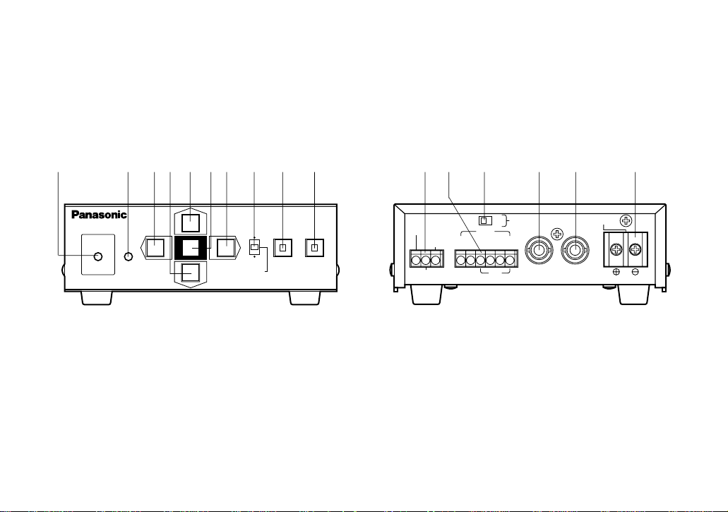
MAJOR OPERATING CONTROLS AND THEIR FUNCTIONS
REMOTE
OPERATE
Camera Controller WV-RM
70
PROG
ALARM
RESET
NORMAL
SYSTEM
ALARM OFF
ON
OFF
INOUT
TERM VIDEO CAMERA DC12V IN
GNDGND
ALARM OUT
RESET OUT
DATA
T(A) T(B) R(A) R(B)
q
w e r t y u i o !0 !1 !2 !3 !4 !5 !6
-4-
Page 7

1. Power Indicator (OPERATE)
This indicator lights up when DC power is supplied
to the DC 12V Input Terminal.
2. Remote Indicator (REMOTE)
This indicator lights up when this controller is controlled remotely by Personal Computer.
3. Left Switch (A)
This switch is used to move the cursor (in the
Setup Menu) in the left direction or move the
Pan/Tilt Head toward the left direction.
4. Down Switch (C)
This switch is used to move the cursor (in the Setup
Menu) in the down direction or move the Pan/Tilt
Head toward the down direction.
5. Up Switch (D)
This switch is used to move the cursor (in the Setup
Menu) in the up direction or move the Pan/Tilt Head
toward the up direction.
6. Set Switch
The mode selected in the setup menu is enabled
by pressing this switch.
7. Right Switch (B)
This switch is used to move the cursor (in the Setup
Menu) in the right direction or move the Pan/Tilt
Head toward the right direction.
8. Mode Selection Switch
(NORMAL/ALARM OFF/SYSTEM)
This switch is used to select the activated mode.
Refer to the Mode Selection on page 13 for more
details.
9. Program Switch (PROG)
This switch is used to display the Program Menu on
the monitor screen by pressing this switch for more
than 2 seconds,
10. Alarm Reset Switch (ALARM RESET)
When the unit is in the alarm mode, this indicator
starts blinking. Press this switch to cancel alarm
and the indicator light turns off.
11. Alarm Terminal
RESET OUT: When the controller resets the acti-
vated alarm by pressing the Alarm Reset
Switch, the alarm reset output signal is provided at this terminal for the Time Lapse VCR.
-5-
Page 8

ALARM OUT: The alarm output signal is provided
at this terminal for the Time Lapse VCR.
12. Data Terminal
These terminals are used to transmit / receive
control data to / from a Personal Computer. Use
data grade cable, suitable for RS-485 (2 shielded,
twisted pairs), cable length may be extended up to
4,000 ft. (1,200m).
14. Video Output Connector (VIDEO OUT)
A 1.0 Vp-p / 75Ω composite video signal is provided at this connector.
15. Camera Input Connector (CAMERA IN)
This connector accepts either a color or B/W composite video signal from the camera. Also, VD2, to
synchronize camera in vertical timing, and data, to
control camera site devices, are multiplexed
through this connector.
Designation
T (A)
T (B)
GND
R (A)
R (B)
GND
Personal Computer ← Controller
Personal Computer ← Controller
Personal Computer → Controller
Personal Computer → Controller
Direction
13. Termination Switch (TERM ON/OFF)
This switch is used to enable termination of this
controller’s data terminal.
16. DC 12V Input Terminal (DC 12V IN)
This terminal accepts 12V DC (10.8 - 16.0V DC)
power source.
Cautions :
1. Connect to a 12V DC class 2 power supply only.
2. To prevent fire or shock hazard, the UL listed
wire VW-1, style 1007 should be used for the
cable for DC 12V Input Terminal.
-6-
Page 9
CONNECTIONS
OPC
VTR
REV
NOR
REV
NOR
SW1
SW2
SW5
SW3
SW4
1234
OFF
VD
VS
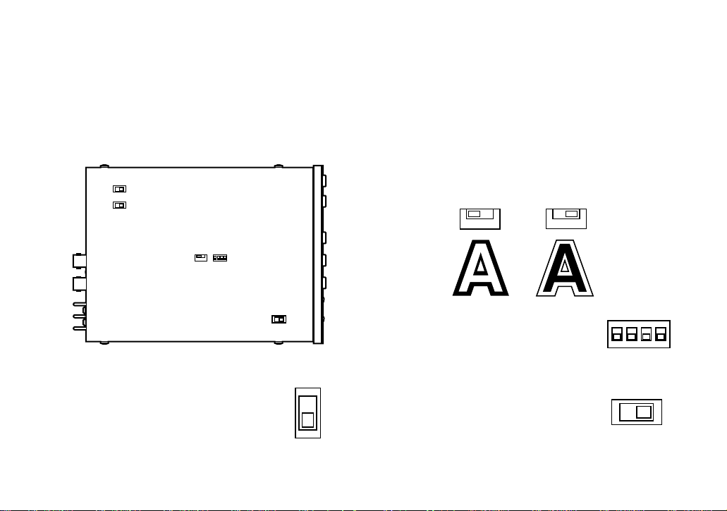
1. Dip Switch Setting
Pulse (VTR): +5V DC approx. 500msec.
Initially, VTR position is selected at the factory.
Before connecting this controller, confirm the Dip
Switch Setting if the system setting change is required.
Rear
1. Set switch (SW1) on the board to
choose the alarm reset output signal as either Open Collector (OPC)
or Pulse (VTR).
Open Collector (OPC) :
16V DC 100mA max.
2. Set switch (SW2) on the board to choose the character display mode on the monitor.
NOR : White with Black border
REV : Black with White border
Initially, normal (NOR) position is selected at the
factory.
Front
3. Confirm switches (SW3) on the
board are set to the position as
shown. These switches are used
only for factory test.
4. Confirm switch (SW4) on the
board is set to the "VS" position.
This switch is used only for factory test.
-7-
Page 10

5. Set switch (SW5) on the board to choose the data
2LINE
4LINE
GND
ALARM OUT
RESET OUT
GND
ALARM OUT
RESET OUT
NC NO
+12V
C
line selection mode for data terminal.
4 LINE : normal connections are
made.
2 LINE : simplified connections
are made.
Initially, 4 LINE is selected
at the factory.
The above switching should be made by qualified
service personal or system installers.
(1) In case the buzzer is operable within the capacity
of Alarm Output Terminal, connect buzzer as
shown right.
(2) In case the buzzer is not operable within the
capacity of Alarm Output Terminal, the external
relay unit should be used as shown below.
2. Connection of Alarm Output Terminal
• Make sure the polarity of the buzzer to meet with
this terminal.
The positive (+) terminal of
the buzzer should be connected with the Alarm Output
Terminal.
• The Alarm Output Terminal is
composed of the Open
Collector Output and the
capacity is 16V DC, 100mA
or less.
NC : Normally Closed
NO : Normally Open
C : Common
Relay
To Buzzer
Buzzer
-8-
Page 11

3. System Connections
TL
■ Basic Connection
Camera WV-CP610
Camera WV-CS304
Camera Controller WV-RM70
Time Lapse VCR
Motion Detect
Output
Monitor
-9-
RS-485
Converter
(RS-485/
RS-232C)
Pan/Tilt
Receiver
Personal Computer
Page 12

■ System 100 ■ System 300
TL
TL
WV-CS304
WV-BS204
Converter
(RS-485/
RS-232C)
RS-485
WJ-SW208
Monitor
WV-CP610 WV-CP610
ALARM OUT
WV-RM70
WV-CU101
Time Lapse VCRPC
-10-
WJ-MP404
WJ-SQ508
WV-CU300
Time Lapse
VCR
Monitor
WV-RM70
Converter
(RS-485/
RS-232C)
Page 13

■ Cable-loss Compensation Setting
The maximum cable length in the system is approximately 3,000 ft.
See the diagram below and set up the cable-loss compensation switch for each unit accordingly.
For examples:
3,000 ft
Camera
A ft
WV-RM70
Camera
WV-RM70
A ft
WJ-MP404
B ft
Position of the
switch of WV-RM70
0 ≤ A < 1300 → S
1300 ≤ A < 2300 → M
2300 ≤ A < 3000 → L
Position of the Position of the
switch of WV-RM70 switch of WJ-MP404
S: 0 ≤ A + B < 1300 → S
S: 1300 ≤ A + B < 2300 → M
S: 2300 ≤ A + B < 3000 → L
M: 1300 ≤ A + B < 2300 → S
M: 2300 ≤ A + B < 3000 → M
L: → S
-11-
Page 14

4. Connection with the Personal
T(A)
T(B)
R(A)
R(B)
R(A)
R(B)
T(A)
T(B)
T(A)
T(B)
R(A)
R(B)
R(A)
R(B)
T(A)
T(B)
T(A)
T(B)
R(A)
R(B)
R(A)
R(B)
T(A)
T(B)
R(A)
R(B)
T(A)
T(B)
T(A)
T(B)
R(A)
R(B)
Computer
■ 4 Data Line (Dip Switch SW5 : 4 LINE)
Personal Computer Camera Controller
■ 2 Data Line (Dip Switch SW5 : 2 LINE)
Personal Computer Camera Controller
Personal Computer Camera Controller
Data Terminal
Camera Controller
Transmit Data
Receive Data
-12-
Page 15

OPERATING PROCEDURE
Before starting the following procedures, all system components should be turned on.
1. Mode Selection
This controller can select the activated mode by selecting Mode Selection Switch located on the front panel.
Switch Position Functions
NORMAL
ALARM OFF
SYSTEM
Activated Mode
Normal Mode
Alarm Off Mode
System Mode
Function 1 : Controller setup
Function 2 : Camera Setup (for WV-CP610 series)
Function 3 : Camera Control
Function 4 : Receiver Control
Function 5 : Alarm Control
Function 6 : Remote Control by Personal Computer
Function 1 : Controller setup
Function 2 : Camera Setup (for WV-CP610 series)
Function 3 : Camera Control
Function 4 : Receiver Control
Function 6 : Remote Control by Personal Computer
Function 1 : Controller setup
Function 5 : Alarm Control
Function 6 : Remote Control by Personal Computer
(Except Camera Site Control)
-13-
Page 16

2. Entering Program Menu
By pressing the Program (PROG) Switch for more
than 2 seconds, when Mode Selection Switch is
selected at Normal (NORMAL) position or Alarm
Off (ALARM OFF) position, the following displays
appear on the monitor screen.
** Program Menu **
Camera Control *
Receiver Control *
Camera Set Up *
Controller Set Up *
Program Menu
Camera Control Iris Control
Sens Up Control
Shutter
BLC
AGC
White Balance
Receiver Control Pan/Tilt Control (Manual)
Zoom/Focus Control
AUX 1, 2 Control
Wiper/Defroster
Pan Action
(Auto/Random Panning)
Fig. 1
As shown in Fig. 2, the Program Menu has four main
sub menus: Camera Control, Receiver Control, Camera
Setup and Controller Setup. These sub menus are further divided in to additional submenus.
Camera Set Up
Controller Set Up System
Communication
Fig. 2
Move the cursor to the desired program by pressing the
Up (D) Switch or the Down (C) Switch on the con-
troller, then press the Set Switch to select program
where the cursor is positioned.
-14-
Page 17

3. Camera Control
Move the cursor to the “Camera Control” position
by pressing the Up (D) Switch or the Down (C)
Switch, then press the Set Switch to display the following display on the monitor screen.
** Program Menu **
Camera Control *
Receiver Control *
Camera Set Up *
Controller Set Up *
Press the Set Switch repeatedly to select the desired
functions. The function is selected as shown in the following sequence.
→ Iris → Sens Up → Shutter → BLC →
← ATW, AWC ← AGC ←
←
close Iris open
B
Fig. 3
→
3-1. Lens Iris Control
The following function is available only when specified lens is mounted on the specified camera.
1. Display the Iris Menu as shown in Fig. 4 by repeating the previous procedures.
←
close Iris open
2. Press the Right (B) Switch to open the lens iris or
press the Left (A) Switch to close the lens iris.
Adjust the lens iris by pressing the switches to
obtain the proper picture exposure.
While pressing the switches, the character is
inversely displayed on the monitor screen.
3. By pressing both of these switches at the same
time for one second, the lens iris is set to the factory preset condition.
→
Fig. 4
-15-
Page 18

3-2. Electronic Sensitivity Up
The following function is available only when specified camera with the electronic sensitivity feature is
used.
3-3. Electronic Shutter
The following function is available only when specified camera with the electronic shutter feature is
used.
1. Display the Sens Up Menu as show in Fig. 5 by
repeating the previous procedures.
↑
Sens Up↓:off
↑
Sens Up↓:←A x10
→
Fig. 5
2. Press the Up (D) Switch or the Down (C) Switch to
select the desired mode, “Off”, “Auto” or “Manu”.
3. When selected “Auto” or “Manu” mode, press the
Right (B) Switch to select a higher sensitivity up
setting, or press the Left Switch to select a lower
sensitivity up setting.
1. Display the Shutter Menu as shown in Fig. 6 by
repeating the previous procedures.
↑
Shutter↓:off
↑
Shutter↓:←/10000
Fig. 6
2. Press the Up (D) Switch or the Down (C) Switch to
select the desired mode, “On” or “Off”.
3. When selected “On” mode, press the Right (B)
Switch to select faster shutter speeds or press the
Left (A) Switch to select slower shutter speeds.
-16-
→
Page 19

3-4. Back Light Compensation (BLC)
The following function is available only when specified camera with the Auto/Preset BLC Function is
used.
1. Display the BLC Menu as shown in Fig. 7 by
repeating the previous procedures.
↑
BLC↓:Auto
Fig. 7
2. Press the Up (D) Switch or the Down (C) Switch to
select the desired mode, “Off”, “Auto” or “Preset”.
3-5. Gain Control
The following function is available only when specified camera with the AGC feature is used.
1. Display the AGC Menu as shown in Fig. 8 by
repeating the previous procedures.
↑
AGC↓:On
Fig. 8
2. Press the Up (D) Switch or the Down (C) Switch to
select the desired mode, “On” or “Off”.
3-6. White Balance
The following function is available only when the
specified camera with the ATW/AWC White
Balance Function is used.
1. Display the ATW, AWC Menu as shown in Fig. 9 by
repeating the previous procedures.
←
ATW,AWC→:ATW
-17-
Fig. 9
Page 20

2. Press the Right (B) Switch or the Left (A) Switch to
select desired mode, “ATW” or “AWC”.
After completing the above settings, press the
Program (PROG) Switch to return the previous
Program Menu as shown in Fig. 1.
To return to the normal camera picture, press the
Program (PROG) Switch again.
4. Receiver Control
Press the Program (PROG) Switch for more than 2 seconds to display the Program Menu.
Move the cursor to the “Receiver Control” position by
pressing the Up (D) Switch or the Down (C) Switch,
then press the Set Switch to display the following display on the monitor screen.
Press the Set Switch repeatedly to select the
desired functions. The function is selected as
shown in the following sequence.
→ Tilt/Pan → Zoom/Focus → Aux →
← Pan Action ← Wiper/Defroster ←
Note : Normally, a WV-RC100 or WV-RC150 Recei-
ver is required to perform the following functions.
4-1. Pan/Tilt Control (Manual Operation)
1. Display the Tilt/Pan Menu as shown in Fig. 11 by
repeating the previous procedures.
** Program Menu **
Camera Control *
Receiver Control *
Camera Set Up *
Controller Set Up *
B
Fig. 10
↑
Tilt↓/ ←Pan
↑
Tilt↓/ ←Pan
→
→
Fig. 11
-18-
Page 21

2. Press the Up (D) Switch or the Down (C) Switch to
move the Pan/Tilt Head toward up or down. Press
the Rignt (B) Switch or the Left (A) Switch to move
the Pan/Tilt Head toward right or left. While pressing these switches, the character is inversely displayed on the monitor screen.
2. Press the Up (D) Switch or the Down (C) Switch to
adjust the lens zoom to achieve the desired picture
while observing the monitor screen.
Press the Up (D) Switch to optically bring an
object closer, pressing the Down (C) Switch has
the reverse effect.
3. If the Up (D) Switch and the Right (B) Switch are
pressed at the same time, the Pan/ Tilt Head
moves diagonally towards Up and Right.
4-2. Zoom/Focus Control
1. Display the Zoom/Focus Menu as shown in Fig. 12
by repeating the previous procedures.
↑
t Z w↓/ ←n F f
→
Fig. 12
3. Press the Right (B) Switch or the Left (A) Switch to
adjust the lens focus to achieve a sharply picture
while observing the monitor screen.
4-3. Auxiliary Control
1. Display the Aux Menu as shown in Fig. 13 by
repeating the previous procedures.
←
1:On Aux →2:Off
Fig. 13
-19-
Page 22

2. Press the Left (A) Switch repeatedly to turn on or
off the user’s auxiliary switch 1 in the Receiver (WVRC100 or WV-RC150).
3. Press the Right (B) Switch repeatedly to turn on or
off the user’s auxiliary switch 2 in the Receiver (WVRC100 or WV-RC150).
4-4. Wiper / Defroster Control
1. Display the Wip / Def Menu as shown in Fig. 14 by
repeating the previous procedures.
←
Wip:Off,→Def:On
Fig. 14
2. Press the Left (A) Switch repeatedly to turn on or off
the housing wiper.
3. Press the Right (B) Switch repeatedly to turn on or
off the housing defroster.
4-5. Pan Action (Auto/Random Panning)
1. Display the Pan Menu as shown in Fig. 15 by
repeating the previous procedures.
←
A Pan:Off R
→
Fig. 15
2. Press the Right (B) Switch or the Left (A) Switch
repeatedly to select the desired Panning mode off,
Auto or Random.
After completing the above settings, press the
Program (PROG) Switch to return the previous
Program Menu as shown in Fig. 1.
To return to the normal camera picture, press the
Program (PROG) Switch again.
-20-
Page 23

5. Camera Set Up
The following functions are only available with the
camera that has set up functions such as the
Panasonic WV-CP610 or WV-BP510 series camera.
1. Press the Program (PROG) Switch for more than 2
seconds to display the Program Menu.
2. Move the cursor to the “Camera Set Up” position
by pressing the Up (D) Switch or the Down (C)
Switch, then press the Set Switch to display the following display on the monitor screen.
Press the Set Switch to execute the selection or
entering the sub menu.
Notes:
• Refer to the Operating Instructions of the camera
for more details.
• While pressing both the Left (A) Switch and the
Right (B) Switch, press the Set Switch for a few
seconds on the SET UP Menu as shown in Fig.16.
At this time all adjustments and selections are
being changed to the factory default settings.
** Program Menu **
Camera Control *
Receiver Control *
Camera Set Up *
Controller Set Up *
B
** SET UP **
CAMERA ID OFF *
ALC/ELC ALC *
SHUTTER OFF
AGC ON
SENS UP OFF
SYNC INT
WHITE BAL ATW *
WIDE D-RANGE OFF
MOTION DET OFF
DNR OFF
END SET UP ENABLE
Fig. 16
3. Select the desired item by pressing the Up (D)
Switch or the Down (C) Switch and then select the
desired mode by pressing the Right (B) Switch or
the Left (A) Switch.
-21-
Page 24

6. Controller Set Up
6-1. Entering Controller Setup Menu
1. Press the Program (PROG) Switch for more than 2
seconds to display the Program Menu.
2. Move the cursor to the “Controller Set Up” position
by pressing the Up (D) Switch or the Down (C)
Switch, then press the Set Switch to display the following display on the monitor screen.
** Program Menu **
Camera Control *
Receiver Control *
Camera Set Up *
Controller Set Up *
Fig. 17
Note: When Mode Selection Switch is selected at
System (SYSTEM) position, Controller Set Up
Menu appears by pressing the Program
(PROG) Switch for more than 2 seconds.
** Controller Set Up **
System *
Communication *
B
Set up Disable
3. Move the cursor to the “Disable” position by pressing the Up (D) Switch or the Down (C) Switch,
then press the Set Switch and “Enable” is displayed.
** Controller Set Up **
System *
Communication *
** Controller Set Up **
System *
Communication *
B
Set up Disable
4. Select the desired item by pressing the Up (D)
Switch or the Down (C) Switch, then press the Set
Switch to select item where the cursor is positioned.
Press the Program (PROG) Switch to return to the
previous Program Menu as shown in Fig. 1.
To return to the normal camera picture, press the
Program (PROG) Switch again.
Set up Enable
Fig. 18
-22-
Page 25

6-2. System Setup
1. Display the Controller Set Up Menu by repeating
the previous procedures.
** Controller Set Up **
System *
Communication *
B
Set up Enable
** System **
Camera ID Off *
Cable Comp S
Alarm Time 60 S
Alarm Display Off
Return
Fig. 19
5. Press the Program (PROG) Switch to return to the
previous Program Menu.
To return to the normal camera picture, press the
Program (PROG) Switch again.
(1) Camera ID Setting
1. Display the System Menu as shown in Fig. 20
by repeating the previous procedures.
** System **
Camera ID Off *
Cable Comp S
Alarm Time 60 S
Alarm Display Off
2. Move the cursor to the “System” position by pressing the Up (D) Switch or the Down (C) Switch,
then press the Set Switch to display the System
Menu as shown in Fig. 19.
3. Move the cursor to the desired item by pressing
the Up (D) Switch or the Down (C) Switch and
then select the desired mode by pressing the Right
(B) Switch or the Left (A) Switch.
4. After completing the above settings, move the cursor to the “Return” Position then press the Set
Switch to return to the previous Controller Set Up
Menu.
Return
Fig. 20
2. Move the cursor to the “Camera ID” position
by pressing the Up (D) Switch or the Down
(C) Switch, then select either “On” or “Off”
mode by pressing the Right (B) Switch or the
Left (A) Switch.
3. When the Camera ID needs editing, perform
the following steps by using the sub menu of
Camera ID.
-23-
Page 26

4. Move the cursor to the “Camera ID” position
by pressing the Up (D) Switch or the Down
(C) Switch, then press the Set Switch to display the Camera ID Editing Menu as shown in
Fig. 21.
Character Cursor
Editing Cursor
ABCDEFGHIJKLM
NOPQRSTUVWXYZ
0123456789
().,'":;&#!?=
+-*/%$
←→
Space
Posi Return Clear
................
Fig. 21
Character
Areas
Command
Editing
Area
ABCDEFGHIJKLM
NOPQRSTUVWXYZ
0123456789
().,'":;&#!?=
+-*/%$
←→
Space
Posi Return Clear
..........
DOOR
Fig. 22
7. When the position of the editing cursor is to be
shifted in the editing area, move the character
cursor to the “←“ or “→“ by pressing the
switches, then press the Set Switch.
This function is used to move the editing position or to correct an individual character.
5. Move the character cursor to the desired letter
by pressing the Up (D) Switch, Down (C)
Switch, Right (B) Switch and Left (A) Switch,
then press the Set Switch.
The selected letter is written to the editing cursor and the editing cursor moves to right automatically.
6. Repeat the above procedure until all character
editing is completed.
-24-
ABCDEFGHIJKLM
NOPQRSTUVWXYZ
0123456789
().,'":;&#!?=
+-*/%$
N
←→
Space
Posi Return Clear
..........
DOOR
N
Fig. 23
Page 27

8. When blank space is needed, move the character cursor to the “Space” position by pressing the switches, then press the Set Switch.
The blank space is inserted into the cursor
position in the editing area.
ABCDEFGHIJKLM
NOPQRSTUVWXYZ
0123456789
().,'":;&#!?=
+-*/%$
←→
Space
Posi Return Clear
DOOR
N
..........
N
Fig. 24
9. When all characters in the editing area are to
be erased, move the character cursor to the
“Clear” position by pressing the switches, then
press the Set Switch.
ABCDEFGHIJKLM
NOPQRSTUVWXYZ
0123456789
().,'":;&#!?=
+-*/%$
←→
Space
Posi Return Clear
..........
DOOR
N
Fig. 25
10. After completing the editing Camera ID, the
Camera ID display position on the monitor
screen can be set as follow. Move the character cursor to the “Posi” position by pressing the
switches, then press the Set Switch to display
the Camera ID as shown in Fig. 26.
ABCDEFGHIJKLM
NOPQRSTUVWXYZ
0123456789
().,'":;&#!?=
+-*/%$
←→
Space
N
Posi Return Clear
..........
DOOR
B
.........
DOOR
Fig. 26
-25-
Page 28

The Camera ID display position can be placed
anywhere on the screen by pressing the Up
(D) Switch, Down (C) Switch, Left (A) Switch
and Right (B) Switch.
Notes :
1. The positioning of the Camera ID stops at
the edges of the monitor screen except
the right side of the monitor screen.
2. The Camera ID moves faster when the Up
(D) Switch, Down (C) Switch, Right (B)
Switch or Left (A) Switch is kept pressed.
(2) Cable Compensation Setting
1. Display the System Menu as shown in Fig. 27
by repeating the previous procedures.
** System **
Camera ID Off *
Cable Comp S
Alarm Time 60 S
Alarm Display Off
Return
11. After completing the positioning, press the Set
Switch to return to the Camera ID Editing Menu
as shown in Fig. 21.
12. Move the Character cursor to the “Return”
position by pressing the switches, then press
the Set Switch to return to the System Menu.
Fig. 27
2. Move the cursor to the “Cable Comp” position
by pressing the Up (D) Switch or the Down
(C) Switch, then select the most suitable cable
length as shown below by pressing the Right
(B) Switch or the Left (A) Switch repeatedly.
S : Up to 1,300ft (400m)
M : 1,300ft (400m) to 2,300ft (700m)
L : 2,300ft (700m) to 3,000ft (900m)
(When using RG-59U, BELDEN 9259 or equivalent cable)
-26-
Page 29

(3) Alarm Time Setting
1. Display the System Menu as shown in Fig. 27
by repeating the previous procedures.
2. Move the cursor to the “Alarm Time” position
by pressing the Up (D) Switch or the Down
(C) Switch, then select the desired alarm time,
0.5s - 120s, by pressing the Right (B) Switch
or the Left (A) Switch repeatedly.
** System **
Camera ID Off *
Cable Comp S
Alarm Time 60 S
Alarm Display Off
Return
Fig. 28
(4) Alarm Display Setting
1. Display the System Menu as shown in Fig. 27
by repeating the previous procedures.
2. Move the cursor to the “Alarm Display” position by pressing the Up (D) Switch or the
Down (C) Switch, then select either “On” or
“Off” mode by pressing the Right (B) Switch
or the Left (A) Switch repeatedly.
To return to the Controller Set Up Menu, move the
cursor to the “Return” position by pressing the Up
(D) Switch or the Down (C) Switch, then press the
Set Switch.
6-3. Communication Setup
1. Display the Controller Set Up Menu by repeating
the previous procedures.
2. Move the cursor to the “Communication” position
by pressing the Up (D) Switch or the Down (C)
Switch, then press the Set Switch to display the following display on the monitor screen.
** Controller Set Up **
System *
Communication *
Set up Enable
** Communication **
Unit Number 1
Baud Rate 9600
Data Bit 8
Parity Check None
Stop Bit 1
Xon/Xoff Not Use
B
Wait Time Off
Delay Time Off
Alarm Data Off
Return
Fig. 29
-27-
Page 30

3. Move the cursor to the desired item by pressing
the Up (D) Switch or the Down (C) Switch and
then select the desired mode by pressing the Right
(B) Switch or the Left (A) Switch.
4. After completing the above settings, move the cursor to the “Return” position by pressing the Up (D)
Switch or the Down (C) Switch, then press the Set
Switch to return to the previous Controller Set Up
Menu.
5. Press the Program (PROG) Switch to return to the
previous Program Menu.
To return to the normal camera picture, press the
Program (PROG) Switch again.
(1) Unit Number Setting
1. Display the Communication Menu as shown in
Fig. 30 by repeating the previous procedures.
** Communication **
Unit Number 1
Baud Rate 9600
Data Bit 8
Parity Check None
Stop Bit 1
Xon/Xoff Not Use
Wait Time Off
Delay Time Off
Alarm Data Off
Return
Fig. 30
2. Move the cursor to the “Unit Number” position
by pressing the Up (D) Switch or the Down
(C) Switch, then select the desired unit number, 1-16, by pressing the Right (B) Switch or
the Left (A) Switch repeatedly.
(2) Baud Rate Setting
1. Display the Communication Menu as shown in
Fig. 30 by repeating the previous procedures.
2. Move the cursor to the “Baud Rate” position by
pressing the Up (D) Switch or the Down
(C) Switch.
Select the desired baud rate, 1200 - 19200, by
pressing the Right (B) Switch or the Left (A)
Switch repeatedly.
(3) Data Bit Setting
1. Display the Communication Menu as shown in
Fig. 30 by repeating the previous procedures.
2. Move the cursor to the “Data Bit” position by
pressing the Up (D) Switch or the Down (C)
Switch.
Select the desired data bit, 7 or 8, by pressing
the Right (B) Switch or the Left (A) Switch.
-28-
Page 31

(4) Parity Check Setting
1. Display the communication Menu as shown in
Fig. 30 by repeating the previous procedures.
Select desired mode, Not Use or Use, by
pressing the Right (B) Switch or the Left (A)
Switch.
2. Move the cursor to the “Parity Check” position
by pressing the Up (D) Switch or the Down
(C) Switch. Select the desired parity check,
None, Odd or Even, by pressing the Right (B)
Switch or the Left (A) Switch.
(5) Stop Bit Setting
1. Display the Communication Menu as shown in
Fig. 30 by repeating the previous procedures.
2. Move the cursor to the “Stop Bit” position by
pressing the Up (D) Switch or the Down (C)
Switch.
Select the desired stop bit, 1 or 2, by pressing
the Right (B) Switch or the Left (A) Switch.
(6) Xon / Xoff
1. Display the Communication Menu as shown in
Fig. 30 by repeating the previous procedures.
2. Move the cursor to the “Xon / Xoff” position by
pressing the Up (D) Switch or the Down (C)
Switch.
(7) Wait Time Setting
1. Display the Communication Menu as shown in
Fig. 30 by repeating the previous procedures.
2. Move the cursor to the “Wait Time” position by
pressing the Up (D) Switch or the Down (C)
Switch.
Select the desired wait time, Off or 100mS 1000mS by pressing the Right (B) Switch or
the Left (A) Switch repeatedly.
(8) Delay Time Setting
1. Display the Communication Menu as shown in
Fig. 30 by repeating the previous procedures.
2. Move the cursor to the “Delay Time” position
by pressing the Up (D) Switch or the Down
(C) Switch. Select the desired delay time, Off
or 10mS - 100mS, by pressing the Right (B)
Switch or the Left (A) Switch repeatedly.
(9) Alarm Data Setting
This setting determines whether the alarm data
received from the camera is transmitted or not
-29-
Page 32

transmitted by the controller through RS-485 to a
ALARM
RESET
computer.
Select the alarm data transmission mode as follows.
Off: The controller does not transmit alarm data to
the computer.
Auto 1: The controller relays alarm data every time
it receives data from the camera.
Auto 2: The controller transmits alarm data periodi-
cally to give the computer time to process the
latest data before receiving new data. Use this
mode if the computer takes time to process all
of received data.
1. Display the Communication Menu as shown in
Fig. 30 by repeating the previous procedures.
2. Move the cursor to the “Alarm Data” position
by pressing the Up (D) Switch or the Down
(C) Switch. Select the desired mode, “Auto 1”,
“Auto 2” or “Off”, by pressing the Right (B)
Switch or the Left (A) Switch.
To return to the Controller Set Up Menu, move the
cursor to the “Return” position by pressing the Up
(D) Switch or the Down (C) Switch then press the
Set Switch.
Note: For more details on the settings, refer to the
operating instructions of the connected equipment.
7. Alarm Control
(1) Alarm Operation
When this unit receives an alarm from the camera,
such as Panasonic WV-CP610 is activated at
motion detect mode, or camera site receiver WVRC100 or WV-RC150, the Alarm Indicator blinks.
The indicator keeps blinking and “Alarm” is displayed on the monitor screen.
←
Alarm
Notes:
• “Alarm” display position can be placed at
upper or lower right side of the monitor screen.
Refer to the Title Setting on page 23 for setup
method.
• It is available to choose the “Alarm” display
mode on the monitor screen.
Refer to the Alarm Display Setting on page 27
for setup method.
→
-30-
Page 33

q e w
(2) To Cancel Alarm
Press the Alarm Reset (ALARM RESET) Switch for
alarm reset. The indicator light turns off and
“Alarm” display on the monitor screen disappears.
Up Switch
8. All Reset
It is possible to undo all the changes the end user
made to return to the factory settings without having to
go through each individual menu.
This feature is called the ALL RESET operation and is
accomplished as follows :
1. Ensure that the Program Menu is not displayed. (a
normal camera picture is displayed).
2. While pressing both the Left (A) Switch and the
Right (B) Switch, press the Set Switch for more
than 2 seconds. The “All Reset” display appears
momentarily on the monitor screen. At this time all
adjustments and selections are being changed to
the factory default settings.
-31-
Left Switch
Set Switch
Right Switch
Down Switch
Note: When the ALL RESET mode is being per-
formed, the picture may be disturbed momentarily.
This is normal and is not indicative of a problem.
Page 34

SPECIFICATIONS
Power Source : DC12V (DC 10.8V - 16.0V), 230mA
Camera Input : Composite Video Signal: 1.0Vp-p / 75Ω
VD2 Output Signal: 2.5Vp-p / 75Ω
Data Signal: 0.5Vp-p / 75Ω
Video Output : Composite Video Signal: 1.0Vp-p / 75Ω
VD2 Input Signal: more than 1.5Vp-p / 75Ω
(Mode Selection Switch is set at SYSTEM)
Data Signal: 0.5Vp-p / 75Ω
(Mode Selection Switch is set at SYSTEM)
Alarm Output : Open collector output : 16V DC, 100mA max.
Alarm Reset Output : Pulse (VTR) : +5V DC 500msec. or
Open collector output : 16V DC, 100mA max.
Data Input / Output : RS-485
Remote Control Functions
Camera Set Up : For Panasonic WV-CP610 or WV-BP510 series camera
Camera Functions : Electronic Sensitivity Up Mode Select : Auto / Manual / Off
Electronic Shutter : On / Off, Shutter Speed Select
Back Light Compensation : Auto / Preset/Off
Automatic Gain Control : On / Off
White Balance : ATW / AWC
Lens Functions : Iris : Open / Close / Preset
Focus : Near / Far
Zoom : Tele / Wide
Housing : Wiper : On / Off, Defroster : On / Off
Pan / Tilt : Manual Pan : Right / Left, Manual Tilt : Up / Down
Auto Pan : On / Off, Random Pan : On / Off
Auxiliary Switch : Aux 1-2 : On / Off
-32-
Page 35

Ambient Operating Temperature : 14˚F - 140˚F (−10˚C - +60˚C)
Ambient Operating Humidity : Less than 90%
Dimensions : 5-7/16” (W) x 7-5/16” (D) x 2”(H)
138 (W) x 185 (D) x 51 (H) mm
Weight : 1.8 lbs. (0.8 kg)
Weight and dimensions shown are approximate.
Specifications are subject to change without notice.
-33-
Page 36

Video Imaging Systems Company
A Division of Panasonic Broadcast & Television Systems Company
A Unit of Matsushita Electric Corporation of America
Executive Office: One Panasonic Way 4H-2, Secaucus, New Jersey 07094
Regional Offices:
Northeast: One Panasonic Way, Secaucus, NJ 07094 (201) 348-7303
Southeast: 1225 Northbrook Parkway, Suite 1-160, Suwanee, GA 30024 (770) 338-6838
Midwest: 1707 North Randall Road, Elgin, IL 60123 (847) 468-5211
Southwest: 8105 Beltsline Road, Suite 100, Irving, TX 75063 (927) 915-1334
Western: 6550 Katella Ave., Cypress, CA 90630 (714) 373-7840
PANASONIC CANADA INC.
5770 Ambler Drive, Mississauga, Ontario, L4W 2T3 Canada (905)624-5010
PANASONIC SALES COMPANY
DIVISION OF MATSUSHITA ELECTRIC OF PUERTO RICO, INC.
San Gabriel Industrial Park, 65th Infantry Ave. KM. 9.5 Carolina, P.R. 00630 (809)750-4300
N0495-2085 YWV8QA3531CN Printed in Japan
N 19
 Loading...