

Panasonic WV-CW860 User Manual
FRANÇAIS
DEUTSCH ENGLISHESPAÑOL
ITALIANO
Before attempting to connect or operate this product,
please read these instructions carefully and save this manual for future use.
Model No. WV-CW860
WV-CW864E
Colour CCTV Camera
Operating Instructions
2
Wij verklaren als enige aansprakelijke, dat het product
waarop deze verklaring betrekking heeft, voldoet aan de volgende normen of andere normatiefve dokumenten,
overeenkomstig de bepalingen van Richtlijnen 73/23/EEC
en 89/336/EEC.
Vi erklærer os eneansvarlige for, at dette produkt, som
denne deklaration omhandler, er i overensstemmelse med
den følgende standarder eller andre normative dokumenter
i følge bestemmelserne i direktivene 73/23/EEC og
89/336/EEC.
Vi deklarerar härmed värt fulla ansvar för att den produkt till
vilken denna deklaration hänvisar är i överensstämmelse
med standarddokument, eller andra normativa dokument
som framstölls i Direktiv 73/23/EEC och 89/336/EEC.
Ilmoitamme yksinomaisella vastuullamme, että tuote, jota
tämä ilmoitus koskee, noudattaa seuraavia standardeja tai
muita ohjeellisia asiakirjoja, jotka noudattavat direktiivien
73/23/EEC ia 89/336/EEC. säädöksiä.
Vi erklærer oss alene ansvarlige for at produktet som
denne erklæringen gjelder for, er i overensstemmelse med
følgende normer eller andre normgivende dokumenter som
fælger bestemmelsene i direktiven 73/23/EEC og
89/336/EEC.
We declare under our sole responsibility that the product to
which this declaration relates is in conformity with the standards or other normative documents following the provisions
of Directives EEC/73/23 and EEC/89/336.
ENGLISH VERSION
The serial number of this product may be found on the
top of the unit.
You should note the serial number of this unit in the
space provided and retain this book as a permanent
record of your purchase to aid identification in the event
of theft.
Model No.
Serial No.
FOR YOUR SAFETY PLEASE READ THE FOLLOWING TEXT
CAREFULLY.
WARNING
THIS APPARATUS MUST BE EARTHED
IMPORTANT
The wires in this mains lead are coloured in accordance with the following code.
Green-and-yellow: Earth
Blue: Neutral
Brown: Live
As the colours of the wire in the mains lead of this appliance may
not correspond with the coloured markings identifying the terminals in
your plug, proceed as follows.
The wire which is coloured green-and-yellow must be connected
to the terminal in the plug which is marked with the letter E or by the
earth symbol
I or coloured green or green-and-yellow.
The wire which is coloured blue must be connected to the terminal in the plug which is marked with the letter N or coloured black.
The wire which is coloured brown must be connected to the terminal in the plug which is marked with the letter L or coloured red.
CAUTION:
TO REDUCE THE RISK OF ELECTRIC SHOCK,
DO NOT REMOVE COVER (OR BACK), NO
USER SERVICEABLE PARTS INSIDE.
REFER SERVICING TO QUALIFIED SERVICE
PERSONNEL.
CAUTION
RISK OF ELECTRIC SHOCK
DO NOT OPEN
The lightning flash with arrowhead
symbol, within an equilateral triangle,
is intended to alert the user to the
presence of uninsulated "dangerous
voltage" within the product's enclosure that may be of sufficient magnitude to constitute a risk of electric
shock to persons.
The exclamation point within an equilateral triangle is intended to alert the
user to the presence of important
operating and maintenance (servicing) instructions in the literature
accompanying the appliance.
Power disconnection. Unit with or
without ON-OFF switches has power
supplied to the unit whenever the
power cord is inserted into the power
source; however, the unit is operational only when the ON-OFF switch
is in the ON position. Unplug the
power cord to disconnect the main
power for all unit.

3
CONTENTS
PREFACE .................................................................................................................. 4
FEATURES ................................................................................................................ 4
■ Camera Cleaning ............................................................................................... 5
■ Preset Data Uploading or Downloading ............................................................ 5
PRECAUTIONS ......................................................................................................... 5
CONSTRUCTION ..................................................................................................... 7
SETUP ...................................................................................................................... 8
■ Setup Menu ....................................................................................................... 8
■ Setup Menu Description .................................................................................... 11
SETTING PROCEDURES .......................................................................................... 16
■ Menu Display ..................................................................................................... 16
■ Presetting ........................................................................................................... 17
■ Deleting Preset Positions ................................................................................... 22
■ Home Position Setting (HOME POSITION) ........................................................ 22
■ Self Return Setting (SELF RETURN) .................................................................. 22
■ Auto Mode Selection (AUTO MODE) ................................................................. 23
■ Auto Pan Key Setting (AUTO PAN KEY) ............................................................ 25
■ Digital Flip Setting (DIGITAL FLIP) .................................................................... 25
■ Local/Remote Setting (LOCAL/REMOTE) ......................................................... 26
■ Special 1 Menu Setting (SPECIAL 1) ................................................................. 26
■ Camera Setting .................................................................................................. 36
■ RS485 Setup ...................................................................................................... 47
INSTALLATION ......................................................................................................... 49
■ Mounting the Camera ........................................................................................ 49
CONNECTIONS ........................................................................................................ 55
SYSTEM CONNECTIONS ......................................................................................... 57
PREVENTION OF BLOOMING AND SMEAR ........................................................... 58
SPECIFICATIONS ..................................................................................................... 58
ACCESSORIES ......................................................................................................... 59
OPTIONAL ACCESSORIES ...................................................................................... 59
APPENDIX ................................................................................................................ 60
ENGLISH

4
• Outdoor enclosure based on IP66* of
IEC60529 standard
* Waterproof structure resistant to powerful
jetting as classified by the International
Protection code
• Provided with built-in heater and fan
• High quality picture of 752 x 582 pixels
• Minimum illumination of 0.5 lx for colour and
0.03 lx for black/white surveillance
(at AGC ON (HIGH), SENS UP x 2)
• Digital flip allows a 180 ° tilting to trace
objects passing under the camera.
• Privacy zone feature enables users to veil
unwanted zones.
FEATURES
The colour cameras WV-CW860 and WVCW864E are designed for installation in an outdoor video surveillance system.
The camera incorporates the digital signal
processor, pan/tilt mechanism, x22 zoom lens
and RS485 communication interface in a compact outdoor enclosure.
PREF ACE
A newly developed 1/4” CCD makes the camera
suitable for use under extremely low illumination
conditions as well as in daylight.
Setup menus allow the camera to perform surveillance tasks by such means as motion detection, digital flip, patrol-learn and privacy zones.
• Protocol adaptability to Panasonic's protocol
• Auto black/white mode enables the camera
to switch between C/L and B/W in response
to input lights.
•A run of manual operations is memorized in
the patrol-learn mode for repetitive use in
future.
• Built-in digital motion detector and alarm outputs
• 64 preset positions
•360 ° panning at a rotation speed of 300 °/s
• Sync selectable between internal, line-lock
or VD2
• Automatic gain control circuit
•Image hold
• Digital noise reduction effect

5
■ Camera Cleaning
Even if this function is used, noise may be produced on the monitor screen, or the preset position may
deviate in the course of prolonged use.
In such cases, activate the refresh mode on the special 2 menu. (See page 46.)
To use this camera with the WJ-SX550B Matrix Switcher, set the auto cleaning function activated on the
Matrix Switcher side, then clean WV-CW860/WV-CW864E one time a day.
■ Preset Data Uploading or Downloading
To download the preset data from the camera to the controller or upload the downloaded data to the
camera, set the following functions to OFF.
Downloading or uploading the data may not work normally if these functions are set to ON.
•Alarm (See page 32.)
•Preset alarm (See page 35.)
• Cleaning (See page 34.)
•Motion detection (See page 43.)
• Auto mode (See page 23.)
• Self return (See page 22.)
Aim the camera at a motionless object such as a wall, if possible, to download or upload the preset data.
Note: Take notice of the following when uploading the downloaded data to the camera.
• Preset positions may vary. If a preset position has deviated, delete the preset position and set
the correct preset position newly.
• Uploading of WV-CW860/WV-CW864E series preset data to other models (e.g. WV-CS850A
series) may cause an error and failure of the uploading process.
1. Do not attempt to disassemble the camera.
To prevent electric shock, do not remove
screws or covers.
There are no user-serviceable parts inside.
Ask a qualified service personnel for servicing.
2. Handle the camera with care.
Do not misuse the camera. Avoid striking,
shaking, etc. The camera could be damaged by improper handling or storage.
3. Consult an expert on the load bearing
capacity of the installation surface and
structure. If the surface is not strong
enough, the camera may fall down. Refer
to the product specifications for weights.
4. Do not install the camera in places where
it will be exposed to corrosive gasses,
e.g., in chemical plants, seaside, at swimming pools or the like. Otherwise corrosion of the bracket may cause the camera
to fall down.
5. Use the fall-prevention wires to reduce
the risk of the camera falling down.
Do not detach the fall-prevention wire securing the camera. Otherwise the camera could
fall down, causing injury to persons and
damage to the camera.
PRECAUTIONS

6
6. Do not use strong or abrasive detergents
when cleaning the camera body.
Use a dry cloth to clean the camera when it
is dirty.
When the dirt is hard to remove, use a mild
detergent and wipe gently. Care should be
taken not to scratch the dome cover when
wiping it.
Afterwards, wipe off the remaining detergent
with a dry cloth.
7. Never aim the camera at the sun.
Whether or not the camera is in use , never
aim it at the sun or other extremely bright
objects. Otherwise, blooming or smear may
be caused.
8. Never aim the camera at strong light
sources for an extended period of time.
Alight source such as a spot light causes
burn-in on the display screen. Failure to
observe this may cause the image to
become discoloured due to deterioration of
the colour filter in the CCD.
9. Do not aim the camera at the same object
for a long time.
Burn-in of an image may be caused on the
fluorescent screen of CRT.
10. Do not install this camera upside down.
This camera is designed for mounting on the
ceiling or wall. Using this camera installed
upside down, for example, mounted on the
floor, may cause malfunction.
11. If “OVER HEAT” appears on the monitor
screen.
The temperature inside the camera exceeds
the normal level because of a malfunction of
the cooling fan etc. If this happens, turn the
power off immediately and refer servicing to
qualified service personnel.
12. Do not operate the camera beyond the
specified temperature, humidity or power
source ratings.
Use the camera under conditions where
temperatures are between –30 °C and
+50 °C (–22 °F to 122 °F), preferably –10 °C
(14 °F) to +40 °C (104 °F), and humidity is
below 90 %.
The input power source is 220 V to 240 V AC
for WV-CW860 or 24 V AC for WV-CW864E.
We recommend that you install the optional
sun shield when the camera is exposed to
direct sunshine where the ambient temperature exceeds +40 °C (104 °F).
Picture quality and camera performance are
not guaranteed until the inside temperature
has risen to –10 °C (14 °F) after turning on
the camera in a cold atmosphere. Wait until
the built-in heater warms up the unit and the
lens and pan/tilt head start searching their
origins.
13. Consumables
Parts having contacts such as the lens-drive
motors, cooling fan motor and slip-rings
inside the camera are subject to wear with
time. Please ask the nearest service centre
about replacement and maintenance of such
parts.
14. Do not install the camera in places subject to vibrations.
Shock absorbers should be installed together with the camera in such places as
bridges, airplanes, vehicles, or near vibration sources.
• Matsushita Electric Industrial Co., Ltd. herewith declares that it will not be liable for any
damage, whether direct or indirect, caused
by using the product for business transaction or security, or malfunctioning of this
product.
7
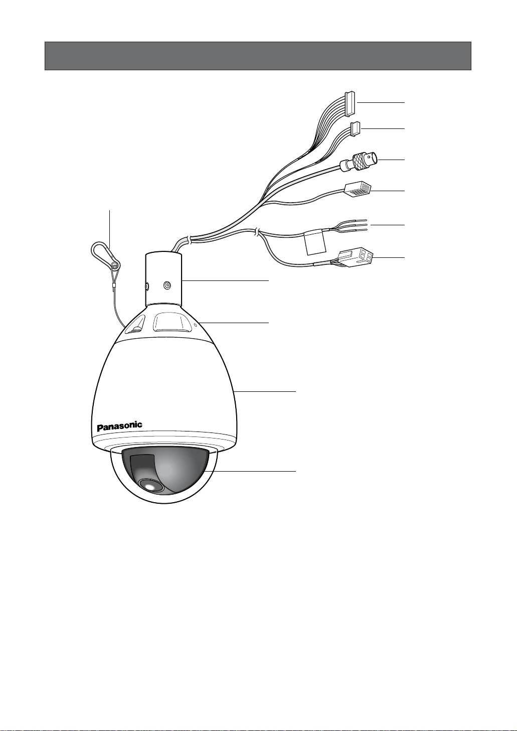
y Attachment Pipe
u Upper Base
i Fall Prevention Wire
o Enclosure
!0 Dome
q Alarm Input Connector
w Alarm Output Connector
e Video Output Connector
r Data Port
t Power Cord for WV-CW860
t* Power Cord for WV-CW864E
CONSTRUCTION
i
q
w
e
r
y
u
o
!0
INPORTANT
WARNING
t
(WV-CW860)
t*
(WV-CW864E)
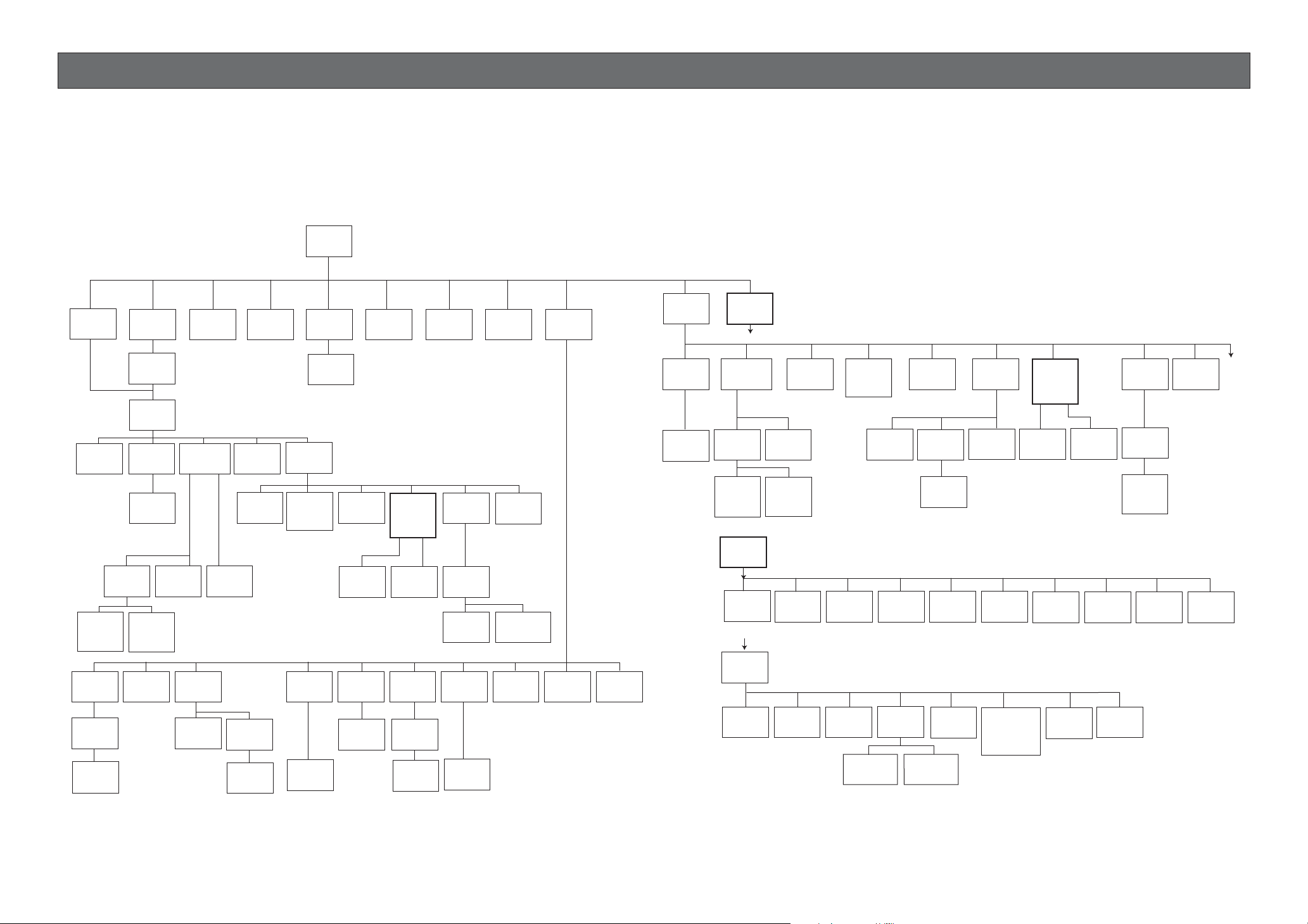
SETUP
Setup Menu
Setup menus are shown in the diagram below. You can adapt the camera to your requirements by setting
up the respective items in these menus. Menus are built in a hierarchical structure, from the Setup menu
at the top to Manual Mask Area Selection at the bottom.
These menus are described in the following pages for reference prior to setup.
Switches, keys and the joystick are used in the setup operations.
Setup
Menu
PRESET
Menu
Position
Setting
Manual
Level
Adjustment
Privacy Zone
ON/OFF
Zone
Number
Selection
Zone
Parameter
Setting
BLC
OFF
MAP
Menu
Preset
No. SET
Menu
Preset
Setting
Menu
Preset
ID
Setting
Preset
ID
Editing
Manual
Mask
Area
Selection
Propo.
P/T
ON/OFF
Selection
Control
ALC/MANUAL
BLC
ON
Area Title
Selection
Direction
Setting
Home
Position
Light
Adjustment
Manual
Iris
Dwell Time
Setting
Shutter
Speed
ON/OFF
Area Title
Editing
Area Title
Display
Self
Return
Setting
Mode
Selection
Auto Pan
Setting
Menu
Scene File
Setting
AGC Mode
Selection
LOW/MID/
HIGH/OFF
Patrol Learn
Play/Stop
Learning
Display
Auto
Auto Pan
Electronic
Sensitivity
Up ON/OFF
Manual
Level
Adjustment
Alarm
IN/OUT
Alarm
IN/OUT
Setting
Key
Setting
ATW1/ATW2
White
Balance
AWC
Manual
Level
Adjustment
Password
Lock
ON/OFF
Password
Verification
Password
Registration
Digital
Flip
ON/OFF
Detector
ON/OFF
Sensitivity
Adjustment
Selection
Cleaning
ON/OFF
Cleaning
Motion
Level
Mask
Area
Display
Local/
Remote
Selection
AF Mode
Selection
Demonstration
Display
EL-Zoom
ON/OFF
Special
1
Preset
Alarm
ON/OFF
Image Hold
ON/OFF
Camera
Menu
CAMERA ID
Editing
CAMERA ID
Display
Position
RS-485
Setup
Light
Control
ALC/MANUAL
BLC
OFF
Manual
Level
Adjustment
(Contrast)
RS-485
Setup
A
Unit
Number
Selection
B
Special
2
Chroma
Gain
Adjustment
To
A
BLC
Manual
Mask
Area
Selection
Adjustment
Shutter
Selection
ON
Sub-
Address
AP
Gain
Speed
AGC Mode
Selection
LOW/MID/
HIGH/OFF
BAUD
Rate
Selection
Pedestal
Adjustment
B/W Auto
Duration
INT
Manual
Selection
Data
Bit
Selection
B/W
ON/OFF/AUTO
Selection
LOW/HIGH
Sensitivity
Up
ON/OFF
LL
Manual
Selection
V-phase
Manual
Adjustment
Selection
B/W Auto
Level
Parity
Check
Selection
Burst
ON/OFF
Sync
INT/LL
VD2
Automatic
Selection
Stop
Bit
Selection
Reduction
Mode selection
LOW1/LOW2/
HIGH1/HIGH2
White
Balance
AWC
ATW1/ATW2
Manual
Level
Adjustment
Xon/Xoff
Selection
RefreshDigital Noise
Manual
Level
Adjustment
Wait
Time
Selection
Camera
Reset
Motion
Detector
ON/OFF
Manual
Level
Adjustment
Manual
Mask
Area
Selection
Alarm
Data
Selection
AF MODE
Selection
Delay Time
Selection
To
B
8
9

10
Open Special 2 F2 key
The keys (switches) to use for setup are shown in the table below. The joystick on the connected controller may also be used for setup. The table also shows the functions versus the operations of the individual controllers. For details, see the manual for the controller to be used. Switches and controls are abbreviated as SW and CTRL respectively in the table.
OPERATE LOGIN ALARM
FUNCTION
SX
IRIS
CLOSE OPEN
NEAR FAR
WIDE TELE
FOCUS
ZOOM
AUTO FOCUS
IRIS RESET
HOME
SET UP
ALM RECALL
CAM SETUP
CAM FUNCTION
MULTI SCREEN
DEF
WIPER
EL-ZOOM
SHIFT
ALM RESET
VTR CAM
STILL
-1 CAM/DEC
ALM SUSPEND
+1 CAM/INC
PATROLSTOP
AUX 1
AUX 2
B/W UNIT
SEQ PAUSE
BOOST
SEQUENCE AUTO
PRESET
POSI
FS
MON
CAM
LOGOUT
ESC SET
CAMERA SITE CONTROL
UP
LR
DOWN
BUSY PROHIBITED
MONITOR
UNIT
CAMERA
System Controller
WV-CU
360
1 2 3
4 5 6
7 8 9
MON CAM
ESC SET
0
ACK
RESET
BACK
SEQ
FORWARD
SEQ ALT
DEC
–1CAM
INC
+1CAM STOP
12
AUX
CLOSE OPEN
IRIS
PRESET
FOCUS
NEAR
ZOOM
TELE
FARWIDE
System Controller WV-CU550550B
LEFT RIGHT
UP
DOWN
ALARM BUSY
F3 F4F2F1
AF
[WV-CU550B]
[WV-CU161]
[WV-RM70]
Joystick
CAM (SET)
Key
MON (ESC)
Key
CAM (SET)
Key
MON (ESC)
Key
SET Key
CAM (SET) Key
OPERATE
REMOTE
NORMAL PROG
ALARM
RESET
SYSTEM
ALARM OFF
Camera Controller WV-RM
7070
Up Switch
Set Switch
Right
Switch
Left Switch Down
Switch
[WV-CU360]
Joystick
Joystick
FOCUS Switch
ZOOM Switch
FOCUS Switch
ZOOM Switch
Up Switch
R
System Controller WV-CU
1 2 3
4 6
7 8 9
0
5
SHIFT
OPERATE ALARM
RESET
RESET
SUSPEND
CAMERA
SETUP
PATROL
PAY
PROGRAM
PRESET
CAMERA
FUNCTION
SERUP
ESC
HOME
SET
PRESET
WIDE TELE
NEAR
AUX1
B/W
AUTO
WIPER
AUX2
DEF
UP
DOWN
L
FAR
FOCUS
IRIS
CLOSS OPEN
PROGRAM
ALARM
IRIS RESET
AUTO FOCUS
Left Switch
Right Switch
Down Switch
Function/Controller WV-CU550B WV-CU360 WV-CU161 WV-RM70
Open CAM SETUP See page 16
CAM SETUP
key (for 2 seconds or more)
CAMERA SETUP
key (for 2 seconds or more)
See page 16
Close CAM SETUP F4 key
CAM SETUP
key (for 2 seconds or more)
CAMERA SETUP
key (for 2 seconds or more)
PROG SW
Move the cursor
Joystick
(←, ↑, ↓, →)
Joystick
(←, ↑, ↓, →)
Direction SW
(←, ↑, ↓, →)
Direction SW
(←, ↑, ↓, →)
Select a parameter
Joystick
(←, →)
Joystick
(←, →)
Direction SW
(←, →)
Direction SW
(←, →)
Adjust the level
Joystick
(←, →)
Joystick
(←, →)
Direction SW
(←, →)
Direction SW
(←, →)
Move the camera
direction
Joystick
(←, ↑, ↓, →)
Joystick
(←, ↑, ↓, →)
Joystick
(←, ↑, ↓, →)
Direction SW
(←, ↑, ↓, →)
Zoom & Focus
ZOOM CTRL &
FOCUS CTRL
ZOOM CTRL &
FOCUS CTRL
ZOOM CTRL &
FOCUS CTRL
Direction SW
(←, ↑, ↓, →)
Enter the setting CAM (SET) key CAM (SET) key CAM (SET) key SET SW
Open a submenu CAM (SET) key CAM (SET) key CAM (SET) key SET SW
Enter CAM ID &
PRESET ID
display position
MON (ESC) key MON (ESC) key MON (ESC) key
SET SW
(for 2 seconds
or more)
Enter MASK
setting
MON (ESC) key MON (ESC) key MON (ESC) key
SET SW
(for 2 seconds
or more)
All Reset F3 key
4+5+6 key
(for 2 seconds
or more)
4+5+6 key
(for 2 seconds
or more)
R+SET+L SW
(for 2 seconds
or more)
4+6 key
(for 2 seconds
or more)
4+6 key
(for 2 seconds
or more)
R+L SW
(for 2 seconds
or more)
Notes:
•A changed parameter is entered only when you move the cursor to
another item or open a new menu. If you close the setup menu without
either of the above actions, the changed parameter will not be entered.
• Setting procedures on the following pages are described on the
assumption that the camera is used with the WJ-SX550B Matrix Switcher
and WV-CU550B System Controller.

11
■ Setup Menu Description
● Presetting
(1) Position (POSITION SET)
Aligns the camera position and focal point by panning, tilting, zooming and focusing.
See page 17 for the setting.
(2) Preset Identification (PRESET ID)
Assigns the name for preset IDs (identification of up to 16 alphanumeric characters) and can be
switched on or off on the monitor screen.
See page 19 for the setting.
(3) Light Control (ALC/MANUAL)
Selects the ALC or MANUAL mode for adjusting the lens iris.
See page 20 for the setting.
(4) Dwell Time (DWELL TIME)
Displays the picture at each camera position for the selected duration.
You can select a preset duration from the menu.
See page 21 for the setting.
(5) Scene File (SCENE FILE)
Stores up to 10 files.
Each file has a set of detailed parameters for the shutter speed, AGC, electronic sensitivity enhancement, white balance, motion detector and AF mode. The scene files can be recalled later to reproduce the parameter settings under the same conditions as stored in the files.
See page 21 for the setting.
●
Home Position (HOME POSITION)
The home position is the camera’s basic position.
The camera returns to this position automatically after a specific time.
Following a manual operation. This setting functions only when AUTO MODE is OFF.
See page 22 for the setting.
● Self Return (SELF RETURN)
Self-return is the time-out parameter for returning to the home position.
In ON position, the camera returns to AUTO MODE after a specific time following a manual operation.
See page 22 for the setting.
● Auto Mode (AUTO MODE)
The auto mode is used for setting the movement of the camera.
You can select one of four automatic operation modes and one manual operation mode as follows:
OFF: No automatic operation. The camera can be operated only manually.
SEQ: The camera operates in the sequence of preset positions in numerical order.
SORT: The camera operates in the sequence of preset positions counterclockwise from Pan Starting
Point.
AUTO PAN: The camera automatically turns within the preset panning range.
PATROL: The camera operates in the patrol-learn function.
See page 23 for the setting.

12
● Auto Pan Key (AUTO PAN KEY)
This setting assigns the SEQ, SORT, AUTO PAN or PATROL (PLAY) mode to the AUTO key on the controller.
After this setting, the AUTO key performs as assigned.
Note: The AUTO PAN LED on the controller does not light if a mode other than AUTO PAN is assigned.
● Digital Flip (DIGITAL FLIP)
In ON position, digital flip widens the range to 0 ° - 180 ° by reversing horizontal and vertical scanning
when the camera is tilted through the 90 ° (downright position if the camera is installed on a ceiling). If
PAN LIMIT is in ON position, the tilt range is narrowed from 180 ° to 90 °.
● Local/Remote (LOCAL/REMOTE)
This setting determines whether the camera continues or stops the ongoing auto operation when the controller is turned off.
LOCAL: The camera continues operating in the auto mode when the controller is turned off.
REMOTE: The camera stops operating in the auto mode approx. 1 minute after the controller is turned
off.
See page 26 for the setting.
● Special 1 Menu
(1) Privacy Zone (PRIVACY ZONE)
This setting is used for masking unwanted zones, hiding them from display on the monitor screen. Set
PASSWORD LOCK to OFF(DIS) if you want to change this setting.
Up to 8 zones can be registered. Submenus are provided for zone number selection and parameter
setting. See page 26 for details.
(2) Proportional Pan-Tilt Speed (PROPO. P/T)
If ON is selected, the pan-tilt speed changes automatically corresponding to the zoom ratio. For
example, the pan-tilt speed slows down when the camera zooms in. See page 28 for details.
(3) Area Title (AREA TITLE)
Up to 8 area titles can be assigned to specific scenes on the DIRECTION (NESW) menu or by
alphanumeric (USER) assignment. The area title is displayed under the camera ID on the monitor
screen when the camera turns to a position that has been assigned an area title. See page 28 for
details.
(4) Patrol-learn and Patrol Play (PATROL)
A set of manual operations is stored (LEARN), reproduced (PLAY) or turned inactive (OFF). Patrol
operation stops if SEQ, SORT or AUTO PAN is set to AUTO MODE on the SETUP menu. See page 30
for details.
(5) Alarm Input/Output (ALARM IN/OUT)
Alarm input and output are set on a submenu. Preset positions are assigned to ALARM IN 1 to 4.
When alarm inputs are supplied via the alarm input connector, the camera turns to the respective
positions. Then the camera sends output signals via the alarm output connector or the coaxial cable
to the external devices. The B/W mode may be chosen if light is insufficient. CNT-CLS (Contact
Closure) 1, 2 and COAX ALM OUT are used for alarm output setting. See page 32 for details.

13
(6) Password Lock (PASSWORD LOCK)
This setting controls access to the privacy zone to be free or limited. If PASSWORD LOCK is set to
ON, ON(DIS) or OFF(DIS) for PRIVACY ZONE appears on the SPECIAL 1 menu.
(7) Cleaning (CLEANING)
This is used for refreshing the electro-mechanical contacts built into the camera. Use this function for
maintenance when the camera has been directed at a specific spot or panned over a specific range
for a long time.
(8) Electronic Zoom (EL-ZOOM)
Up to 10-fold electronic zooming is available besides 22-fold optical zooming.
(9) Preset Alarm (PRESET ALM)
Alarm signals are output in the following cases if ON is selected.
• When a preset positioning sequence is completed while AUTO MODE is set to SEQ.
• When a preset positioning sequence is completed while AUTO MODE is set to SORT.
• When positioning to the starting point is completed while AUTO MODE is set to AUTO PAN.
• When the self-return function has returned the camera to its home position.
• When preset positioning is completed by manual operation.
• When positioning to the starting point is completed while PATROL is set to PLAY.
(10)Image Hold (IMAGE HOLD)
The camera picture remains as a still image on the monitor screen or until the camera reaches the
preset position. This function is useful for surveillance via a local area network.
● Camera
(1) Camera Identification (CAMERA ID)
You can use the camera identification to assign a name to the camera. The camera ID consists of up
to 16 alphanumeric characters. You can select whether to have the camera ID displayed on the monitor screen or not. See page 36 for the setting.
(2) Light Control (ALC/MANUAL)
You can select the mode for adjusting the lens iris. There are two modes as follows:
ALC: The lens iris is automatically adjusted according to the brightness of an object.
You can select one of two modes (BLC ON or BLC OFF) of backlight compensation.
Backlight compensation is available in the ALC mode. It eliminates strong background light
which makes the camera picture dark such as a spotlight.
MANUAL: The lens iris is fixed at the value that you have set regardless of the brightness of an
object.
• ALC Mode with BLC ON
An important object in a scene is usually placed in the centre of the monitor screen. By activating this
feature, more photometric weight is given to the centre of the screen than to the edge of the screen
(where bright backlight would most likely be located). In such a case, the object at the centre of the
screen can be still clearly seen even though the backlight may vary.
See page 37 for the setting.
• ALC Mode with BLC OFF
This mode is effective when the main object in the scene is not located in the centre of the screen but
a source of bright light is located near the centre of the scene. In this mode, the picture is divided
into 48 areas that mask the light to keep the clarity of the picture.

14
Note: The result of field setup of the mask area and level adjustment is fed back (effected) to the lens
iris control in ALC mode.
(3) Shutter Speed (SHUTTER)
You can select a shutter speed from among 1/50 (OFF), 1/120, 1/250, 1/500, 1/1 000, 1/2 000,
1/4 000, and 1/10 000 seconds.
See page 39 for the setting.
(4) Gain Control (AGC)
You can set the gain of an image to automatic adjustment [AGC ON (LOW, MID, HIGH)] or fixed
(AGC OFF).
See page 39 for the setting.
(5) Electronic Sensitivity Enhancement (SENS UP)
The electronic sensitivity enhancement function varies the shutter speed to raise the sensitivity in low
light conditions.
You can select the following shutter speeds for SENS UP.
1/25 seconds (x2), 1/12.5 seconds (x4), 1/8.3 seconds (x6), 1/5 seconds (x10), 1/3.1 seconds (x16),
or 1/1.6 seconds (x32).
See page 39 for the setting.
There are two modes for SENS UP as follows:
AUTO: If you select x32, the sensitivity is raised automatically up to x32.
FIX: If you select x32, the sensitivity is raised to a fixed x32.
Notes:
• Moving objects will appear blurred when shot in electronic sensitivity enhancement mode since
SENS UP is equivalent to reducing the shutter speed in a still picture camera.
• The horizontal and vertical resolution will be lowered in this mode.
• If the iris opening is too small, the SENS UP/AUTO mode will not function.
(6) Synchronization (SYNC)
You can select the internal sync (INT) mode or the line-lock sync (LL) mode. Additionally, this model
accepts the VD2 signal from a specified component. Whenever the VD2 signal is supplied to this
camera, the camera automatically switches to the VD2 sync mode.
When you select the line-lock (LL) mode, you can adjust vertical phase .
See page 40 for the setting.
Important Notices:
The priority of sync modes is given as follows:
1. Multiplexed vertical drive (VD2) (highest)
2. Line-lock (LL)
3. Internal sync (INT) (lowest)
Note: The priority of the automatic sync modes is the same as shown above.

15
(7) White Balance (WHITE BAL)
You can select either of three modes shown below for white balance adjustment:
• Auto-Tracing White Balance (ATW1)
In this mode, the colour temperature is monitored continuously and thereby white balance is set automatically. The colour temperature range for the proper white balance is approx. 2 600 - 6 000 K.
Proper white balance may not be obtained under the following conditions:
1. The colour temperature is out of the 2 600 - 6 000 K range.
2. When the scene contains mostly high colour temperature (bluish) objects, such as a blue sky.
3. When the scene is dim.
In these cases, select the AWC mode.
• Auto-Tracing White Balance (ATW2)
This mode enables the camera to trace the white balance when it is used in an area lit by sodium
lamps.
• Automatic White Balance Control (AWC)
In this mode, accurate white balance is obtained within a colour temperature range of approx. 2 300 10 000 K.
See page 42 for the setting.
(8) Motion Detector (MOTION DET)
The motion detector detects motion in a scene by monitoring changes in the brightness level. You
can select the sensitivity level for the motion on the setup menu.
When the camera detects motion, it sends the alarm signal to the external equipment and stops at its
position for the preset dwell time.
See page 43 for the setting.
(9) Auto Focus (AF MODE)
The camera adjusts the focus automatically by sensing the centre of the picture. S, M and L stand for
the size of the sensing area: Small, Middle and Large.
See page 44 for details.
MANUAL S, M, L: Auto-focus is activated only when the AF key on the controller is pressed.
AUTO S, M, L: Auto-focus is activated automatically while a manual pan, tilt or zoom operation is per-
formed.
Note: If SENS UP is set to ON except x2 FIX or x2 AUTO, the AUTO (S/M/L) mode is disabled and the
MANUAL (S/M/L) mode is automatically selected.
(10)Special 2 Menu (SPECIAL2)
This menu allows you to adjust and set up the following items and functions: chroma level, aperture
level, pedestal level, black and white function, digital noise reduction function and refresh function.
You can also reset your parameters to the factory default settings.
See page 45 for the setting.
● RS485 communication
Refer to the following pages for the communication parameter settings.
• Full/Half duplex (page 54) • Camera units (96 units max.) (page 52)
• Transmission Speed (2 400 - 19 200 bps) (page 48) • Termination ON/OFF (page 54)
• Parity bit, Stop bit, Flow control (page 48) • Reset parameters (page 51)
•Wait time, Delay time, Alarm output (page 48)
16
SETTING PROCEDURES
The following setting procedures are described on the assumption that this model is used in combination
with the WJ-SX550B Matrix Switcher and WV-CU550B System Controller. In case a controller other than
the WV-CU550B is used, refer to the table on page 10.
■ Menu Display
● Setup Menu Display
WV-CU550B
1. Select the camera number you want to set up and a monitor to
display SET UP MENU.
2. Display the D4 menu on the LCD by pressing the appropriate cursor buttons.
3. Press the F1 button.
SET UP MENU appears on the monitor screen.
4. To close SET UP MENU, press the F4 button.
WV-CU360
Press the CAM SETUP key for 2 seconds or more to open the
SETUP menu.
WV-CU161
Press the CAMERA SETUP key for 2 seconds or more to open the
SETUP menu.
WV-RM70
1. Turn the MODE SELECTION switch to NORMAL or ALARM OFF.
2. Press the PROG switch for 2 seconds or more to open the
Program Menu.
3. Move the cursor to Camera Set Up Menu, and press the SET
switch to open the SETUP MENU.
● Submenu Display
The items marked O can be selected/changed on the submenu.
• Move the cursor to an item with the O mark and press the CAM
(SET) key. The submenu appears.
D4 menu
Submenu
(for RS485 setup)
Setup menu
Camera Set Up Menu
On Exit
F2 F3 F4
F1
Camera Set Up Menu
Res A.Res Exit
F1 F2 F3 F4
** SET UP MENU **
PRESET 1
MAP
HOME POSITION
SELF RETURN
AUTO MODE
AUTO PAN KEY
DIGITAL FLIP
LOCAL/REMOTE
SPECIAL1
CAMERA
RS485 SET UP
OFF
OFF
OFF
AUTO PAN
ON
LOCAL
** RS485 SET UP **
UNIT NUMBER
SUB ADDRESS
BAUD RATE
DATA BIT
PARITY CHECK
STOP BIT
XON/XOFF
WAIT TIME
ALARM DATA
DELAY TIME
RET
1
----19200
8
NONE
1
NOT USE
OFF
AUTO2
---
17
■ Presetting
● Preset Menu Display
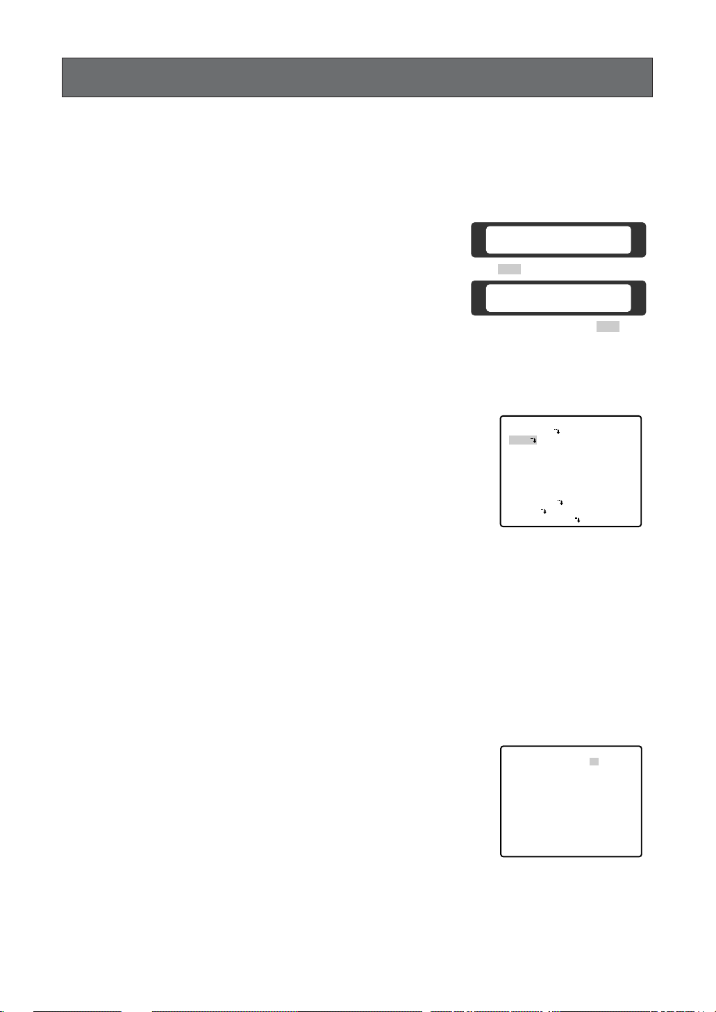
1. Displaying the preset menu directly
(1) Move the cursor to PRESET 1 O and select the position num-
ber by moving the joystick to the right or left.
(2) Press the CAM (SET) key.
The preset setting menu appears on the monitor screen.
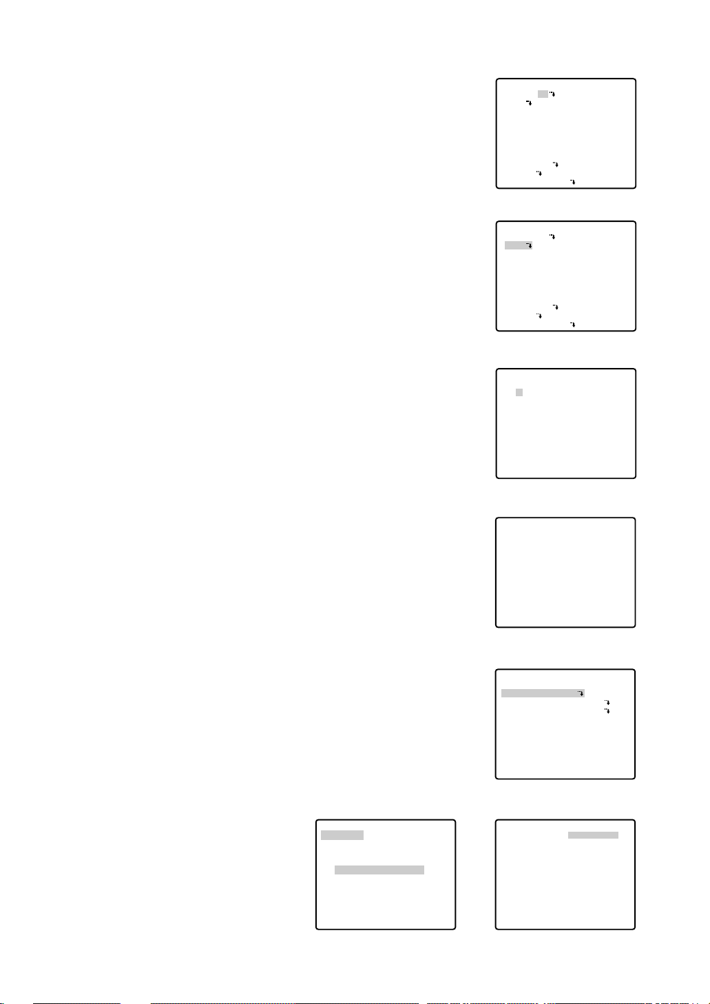
2. Displaying the preset menu from the PRESET NUMBER SET menu
(1) Move the cursor to MAP O and press the CAM (SET) key.
The PRESET NUMBER SET menu appears on the monitor
screen.
(2) Move the cursor to the position number to be set and press
the CAM (SET) key.
The preset setting menu appears on the monitor screen. To
display position number 33-64, move the cursor to “33-64” in
the lower left of the screen and press the CAM (SET) key.
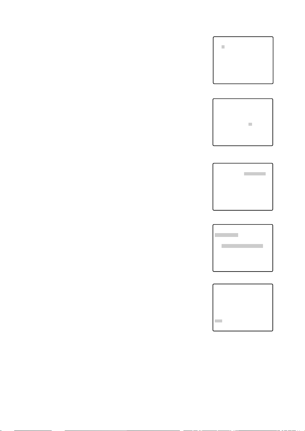
Notes:
• The * mark indicates that the position number has been preset.
• The character H refers to the home position.
• The second line from the bottom shows the preset ID corresponding to the selected number. “DOOR” next to “ID” in the
example shown right is for preset position number 1.
• Preset numbers 1 to 4 are linked to alarm inputs 1 to 4. If
alarm input 1 comes in, the camera turns to preset position 1,
or to other positions according to alarm input 2, 3 or 4.
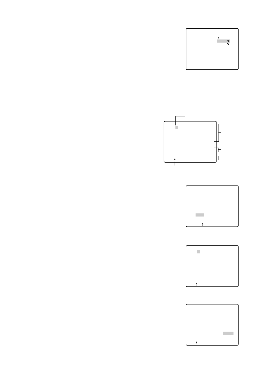
● Position Setting (POSITION SET)
1. Move the cursor to POSITION SET on the preset setting menu and
press the CAM (SET) key.
The position setting menu appears.
2. To Set Panning/Tilting Positions
(1) For PAN/TILT, move the cursor to PUSH SET and press the
CAM (SET) key. The PAN/TILT setting menu appears.
(2) Select panning/tilting positions by using the joystick, and
press the CAM (SET) key.
The positions are set and the screen returns to the position
setting menu.
Setup menu
PRESET NUMBER SET menu
(1-32)
PRESET NUMBER SET menu
(33-64)
Preset setting menu
→
PUSH SET
→
PUSH SET
** POSITION 1 **
PAN/TILT
ZOOM/FOCUS
PAN OFFSET SET
← −
0.0
→
RET
FLOOR1
DOOR
Position setting menu
→
PUSH SET
→
PUSH SET
** POSITION 1 **
PAN/TILT
ZOOM/FOCUS
U TILT D/L PAN R
PAN OFFSET SET
← −
0.0
→
RET
FLOOR1
DOOR
Setup menu
PAN/TILT setting menu
** SET UP MENU **
PRESET 1
MAP
HOME POSITION
SELF RETURN
AUTO MODE
AUTO PAN KEY
DIGITAL FLIP
LOCAL/REMOTE
SPECIAL1
CAMERA
RS485 SET UP
OFF
OFF
OFF
AUTO PAN
ON
LOCAL
** SET UP MENU **
PRESET 1
MAP
HOME POSITION
SELF RETURN
AUTO MODE
AUTO PAN KEY
DIGITAL FLIP
LOCAL/REMOTE
SPECIAL1
CAMERA
RS485 SET UP
OFF
OFF
OFF
AUTO PAN
ON
LOCAL
** PRESET NUMBER SET **
2
1
5
9
13
17
21
25
29
ID:DOOR
33-64 RET
6
10
14
18
22
26
30
3
7
11
15
19
23
27
31
4
8
12
16
20
24
28
32
** PRESET NUMBER SET **
34
33
37
41
45
49
53
57
61
ID:
1-32 RET
38
42
46
50
54
58
62
35
39
43
47
51
55
59
63
36
40
44
48
52
56
60
64
PRESET NO. 1*
POSITION SET
PRESET ID
ALC/MANUAL
DWELL TIME
SCENE FILE
PRESET SPEED
RET DEL
ON
ALC
10S
OFF
••••••••|
L H
18
3. Pan Offset
If the camera is replaced with a new one, the pan offset function
is used to adjust its positions to be the same as before except
patrol setting.
The system controller can download or upload the preset position
data.
Caution: The preset data for other cameras (WV-CS850A for
example) is incompatible with WV-CW860's. WV-CW860's
preset data will be destroyed if you upload the conventional
data. If this happened, reset the WV-CW860/WV-CW864E to
the default settings. Download the factory settings into the
controller and upload the correct preset data newly to the initialized WV-CW860/WV-CW864E.
(1) Display the PRESET NUMBER SET menu.
(2) Select a position number for the picture to be most enlarged
among the numbers by using the joystick. Then press the
CAM (SET) key. The position setting menu appears.
(3) Move the cursor to PAN OFFSET SET and select the right or
left arrow by using the joystick.
(4) Press the CAM (SET) key until the desired offset value
appears.
(5) Move the cursor to an item other than PAN OFFSET SET, and
press the MON (ESC) key.
Notes:
• Further adjustment of the other positions is unnecessary. This
adjustment applies to all other positions.
• Make sure to move the cursor before pressing the key in step
5. Otherwise the settings will be ignored.
• Retry the loading when the camera fails to upload or download the data.
4. To Set the Lens Zoom and Focus Positions
(1) Move the cursor to PUSH SET for ZOOM/FOCUS and press
the CAM (SET) key. The ZOOM/FOCUS setting menu
appears.
(2) Select a zoom position by moving the zoom control up and
down, and a focus position by moving the focus control up
and down, and then press the CAM (SET) key.
The positions are set and the screen returns to the position
setting menu.
Notes:
• When the camera is used at a nearly horizontal angle, the
focus may not be adjustable to a high level of accuracy.
• If you move the cursor to the position number and move the
joystick right or left, the position number can be selected.
The selected preset position number can also be set after
pressing the CAM (SET) key.
• The preset and camera IDs appear in the lower-left corner of
the position setting menu after setting them.
5. Move the cursor to RET and press the CAM (SET) key to return to
the preset setting menu.
Position setting menu
Position setting menu
PRESET NUMBER SET menu
(1-32)
Position setting menu
ZOOM/FOCUS setting menu
** PRESET NUMBER SET **
2
1
5
9
13
17
21
25
29
ID:DOOR
33-64 RET
6
10
14
18
22
26
30
3
7
11
15
19
23
27
31
4
8
12
16
20
24
28
32
** POSITION 1 **
PAN/TILT
ZOOM/FOCUS
PAN OFFSET SET
RET
FLOOR1
DOOR
→
PUSH SET
→
PUSH SET
← −
0.0
→
** POSITION 1 **
PAN/TILT
ZOOM/FOCUS
PAN OFFSET SET
RET
FLOOR1
DOOR
→
PUSH SET
→
PUSH SET
← −
0.0
→
** POSITION 1 **
PAN/TILT
ZOOM/FOCUS
→
PUSH SET
→
PUSH SET
U ZOOM D/L FOCUS R
PAN OFFSET SET
RET
FLOOR1
DOOR
← −
** POSITION 1 **
PAN/TILT
ZOOM/FOCUS
PAN OFFSET SET
RET
FLOOR1
DOOR
→
PUSH SET
→
PUSH SET
← −
0.0
0.0
→
→
19
● Preset Identification Setting (PRESET ID)
1. Move the cursor to PRESET ID on the preset setting menu and
select ON or OFF by moving the joystick to the right or left.
The factory default setting is OFF.
ON: Preset ID appears on the monitor screen.
OFF: Preset ID does not appear.
2. Press the CAM (SET) key to display the preset ID setting menu.
To Enter a New Preset ID
(1) Move the cursor to the desired character using the joystick,
and press the CAM (SET) key.
(2) The selected character appears in the editing area. (The
pointer in the editing area moves to the right automatically at this moment.) To enter a blank, select SPACE.
(3) Repeat the above procedure until all characters are
entered.
To Copy a Preset ID from Another Position
(1) Move the cursor to COPY and press the CAM (SET) key. The
preset ID in the preceding position is immediately shown.
Each consecutive pressing of the CAM (SET) key displays the
ID preceding the one currently displayed.
(2) Display the most prospective ID.
(3) Follow the step “To Change an Entered Preset ID” if neces-
sary.
To Change an Entered Preset ID
(1) Move the pointer to the character to be edited in the editing
area by using the joystick.
(2) Select a new character by using the joystick.
(3) Press the CAM (SET) key to determine the Preset ID.
To Delete an Entered Preset ID
Move the cursor to RESET and press the CAM (SET) key.
Preset setting menu
Preset ID setting menu
PRESET NO. 1*
POSITION SET
PRESET ID
ALC/MANUAL
DWELL TIME
SCENE FILE
PRESET SPEED
ON
ALC
10S
OFF
••••••••|
L H
RET DEL
Character Cursor
PRESET NO. 1*
0123456789
ABCDEFGHIJKLM
NOPQRSTUVWXYZ
().,'":;&#!?=
+-*/%$ДЬЦЖСЕ
SPACE
COPY POSI RET RESET
DOOR............
Pointer
PRESET NO. 1*
0123456789
ABCDEFGHIJKLM
NOPQRSTUVWXYZ
().,'":;&#!?=
+-*/%$ДЬЦЖСЕ
SPACE
COPY POSI RET RESET
DOOR............
Character
Area
Command
Editing
Area
PRESET NO. 1*
0123456789
ABCDEFGHIJKLM
NOPQRSTUVWXYZ
().,'":;&#!?=
+-*/%$ДЬЦЖСЕ
SPACE
COPY POSI RET RESET
DOOR............
PRESET NO. 1*
0123456789
ABCDEFGHIJKLM
NOPQRSTUVWXYZ
().,'":;&#!?=
+-*/%$ДЬЦЖСЕ
SPACE
COPY POSI RET RESET
DOOR............
 Loading...