

Page 1
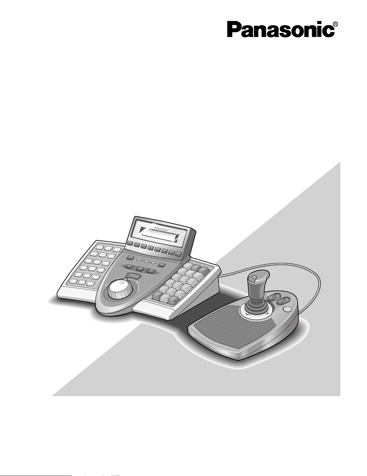
System Controller
Operating Instructions
Model Nos. WV-CU950
WV-CU650
Before attempting to connect or operate this product,
please read these instructions carefully and save this manual for future use.
Page 2
ENGLISH VERSION
Caution:
Refer to the name plate on the rear of this product to verify
identifications and power ratings.
CAUTION
RISK OF ELECTRIC SHOCK
DO NOT OPEN
CAUTION: TO REDUCE THE RISK OF ELECTRIC SHOCK,
DO NOT REMOVE COVER (OR BACK).
NO USER-SERVICEABLE PARTS INSIDE.
REFER SERVICING TO QUALIFIED SERVICE PERSONNEL.
The lightning flash with arrowhead symbol,
within an equilateral triangle, is intended to
alert the user to the presence of uninsulated
"dangerous voltage" within the product's
enclosure that may be of sufficient magni-
SA 1965
SA 1966
tude to constitute a risk of electric shock to
persons.
The exclamation point within an equilateral
triangle is intended to alert the user to the
presence of important operating and maintenance (servicing) instructions in the literature accompanying the appliance.
For U.S.A
NOTE: This equipment has been tested and found to comply with the limits for a Class A digital device, pursuant to
Part 15 of the FCC Rules. These limits are designed to provide reasonable protection against harmful interference
when the equipment is operated in a commercial environment. This equipment generates, uses, and can radiate
radio frequency energy and, if not installed and used in
accordance with the instruction manual, may cause harmful
interference to radio communications.
Operation of this equipment in a residential area is likely to
cause harmful interference in which case the user will be
required to correct the interference at his own expense.
FCC Caution: To assure continued compliance, (example use only shielded interface cables when connecting to computer or peripheral devices). Any changes or modifications
not expressly approved by the party responsible for compliance could void the user's authority to operate this equipment.
The serial number of this product may be found on the bottom of the unit.
You should note the serial number of this unit in the space
provided and retain this book as a permanent record of your
purchase to aid identification in the event of theft.
Model No.
Serial No.
WARNING: To prevent fire or electric shock hazard, do not expose this appliance to rain or moisture. The apparatus shall not be exposed to
dripping or splashing and that no objects filled with liquids, such as vases, shall be placed on the apparatus.
2
Page 3

3
IMPORTANT SAFETY INSTRUCTIONS
1) Read these instructions.
2) Keep these instructions.
3) Heed all warnings.
4) Follow all instructions.
5) Do not use this apparatus near water.
6) Clean only with dry cloth.
7) Do not block any ventilation openings. Install in accordance with the manufacturer's instructions.
8) Do not use near any heat sources such as radiators, heat registers, stoves, or other apparatus (including amplifiers) that
produce heat.
9) Do not defeat the safety purpose of the polarized or grounding-type plug. A polarized plug has two blades with one wider
than the other. A grounding-type plug has two blades and a third grounding prong. The wide blade or the third prong are
provided for your safety. If the provided plug does not fit into your outlet, consult an electrician for replacement of the
obsolete outlet.
10) Protect the power cord from being walked on or pinched particularly at plugs, convenience receptacles and the points
where they exit from the apparatus.
11) Only use attachments/accessories specified by the manufacturer.
12) Use only with the cart, stand, tripod, bracket, or table specified by the manufacturer, or sold with the apparatus. When a
cart is used, use caution when moving the cart/apparatus combination to avoid injury from tip-overs.
13) Unplug this apparatus during lightning storms or when unused for long periods of time.
14) Refer all servicing to qualified service personnel. Servicing is required when the apparatus has been damaged in any way,
such as power-supply cord or plug is damaged, liquid has been spilled or objects fallen into the apparatus, the apparatus
has been exposed to rain or moisture, does not operate normally, or has been dropped.
S3125A
Page 4

4
LIMITATION OF LIABILITY
This product is a system controller to operate PS·Data system units and connected cameras. (A surveillance control
system cannot be composed of this product alone.)
IN NO EVENT SHALL MATSUSHITA ELECTRIC INDUSTRIAL CO., LTD. BE LIABLE TO ANY PARTY OR ANY PERSON, EXCEPT FOR CERTAIN WARRANTY PROGRAM
OFFERED BY THE LOCAL DEALER OF PANASONIC, FOR
THE CASES INCLUDING BUT NOT LIMITED TO BELOW:
(1) ANY DAMAGE AND LOSS, INCLUDING WITHOUT LIM-
ITATION, DIRECT OR INDIRECT, SPECIAL, CONSEQUENTIAL OR EXEMPLARY, ARISING OUT OF OR
RELATING TO THE PRODUCT;
(2) PERSONAL INJURY OR ANY DAMAGE CAUSED BY
INAPPROPRIATE USE OR NEGLIGENT OPERATION
OF THE USER;
(3) UNAUTHORIZED DISASSEMBLY, REPAIR OR MODIFI-
CATION OF THE PRODUCT BY THE USER;
(4) INCONVENIENCE OR ANY LOSS ARISING WHEN
IMAGES ARE NOT DISPLAYED, DUE TO ANY REASON
OR CAUSE INCLUDING ANY FAILURE OR PROBLEM
OF THE PRODUCT;
(5) ANY PROBLEM, CONSEQUENTIAL INCONVENIENCE,
OR LOSS OR DAMAGE, ARISING OUT OF THE SYSTEM COMBINED BY THE DEVICES OF THIRD PARTY.
Page 5

5
IMPORTANT SAFETY INSTRUCTIONS ..............................3
LIMITATION OF LIABILITY .................................................4
PREFACE ............................................................................6
FEATURES ..........................................................................6
PRECAUTIONS ...................................................................7
DOCUMENT CONVENTION ...............................................8
NOTIFICATION ABOUT SYSTEM UNITS ............................8
NOTIFICATION ABOUT
OPERATION MODES...........................................................8
DETAILED PRODUCT DESCRIPTION ..............................9
MAJOR OPERATING CONTROLS
AND THEIR FUNCTIONS ..............................................10
■ Main Unit ...............................................................10
■ 3D Joystick Unit ....................................................14
■ LCD Display Descriptions ....................................15
INSTALLATIONS AND SYSTEM CONNECTIONS..........19
INSTALLATIONS AND CONNECTIONS .......................20
■ Basic System Connections ...................................20
■ Connection with the 3D Joystick Unit ...................21
■ Adjustment of 3D Joystick ....................................21
WV-CU950/650 SETUP PROCEDURES ..........................23
SETUP PROCEDURES (HARDWARE) ..........................24
■ Setup Procedures .................................................24
■ MODE Switch Setting ...........................................24
■ CONTROLLER NO. Switch Setting .......................25
SETUP PROCEDURES (FIRMWARE) ............................26
■ Administrator Password Entry ..............................26
■ Setting Modes .......................................................26
■ All Reset ................................................................26
■ PS·Data Communication Setting ..........................27
■ To Change the Administrator Password ...............31
■ PS·Data Database Copy .......................................32
■ PS·Data Operator Password Check .....................33
OPERATING PROCEDURES (PS·DATA)........................35
BEFORE OPERATION ...................................................36
■ Power-on ...............................................................36
■ Power-off ...............................................................36
■ Basic Operation Flow ...........................................37
■ LCD/Buzzer Adjustment .......................................38
■ Operation Start (Login) .........................................38
■ If You Have Forgotten the Login Password ..........40
■ Operation Start (Auto Login) .................................40
■ Operation End (Logout) ........................................40
UNIT SELECTION .........................................................41
■ System Unit Selection ...........................................41
■ Recorder Selection ...............................................41
■ Monitor Selection ..................................................42
■ Camera Selection .................................................42
SYSTEM UNIT CONTROL .............................................43
■ Multiscreen Display ..............................................43
■ Electronic Zooming ...............................................43
■ Tour Sequence/Group Sequence .........................43
■ On-screen Display (OSD) Control ........................44
■ System Function Control .......................................44
RECORDER CONTROL ................................................45
■ Manual Recording ................................................45
■ Playback ...............................................................45
■ Search Playback ...................................................45
■ Time & Date Search Playback ..............................49
■ Other Available Functions ....................................49
CAMERA CONTROL .....................................................50
■ Camera Panning/Tilting Control ............................50
■ Zooming Control ...................................................50
■ Lens Iris Control ....................................................50
■ Lens Focus Control ...............................................50
■ Preset Position Control .........................................51
■ Home Position Control ..........................................51
■ Camera Function Control ......................................51
■ Camera Position Control .......................................52
■ Camera Selection Recall ......................................52
■ Wiper Control ........................................................52
■ Defroster Control ..................................................53
■ Auxiliary Control ....................................................53
■ Other Functions ....................................................53
ALARM CONTROL ........................................................54
■ System Controller Behavior
during the Alarm Mode .........................................54
■ Alarm Reset ..........................................................54
■ Alarm Suspension .................................................54
■ Alarm History Search ............................................54
MENU FUNCTION DESCRIPTIONS ..............................57
■ Menu Flow ............................................................57
■ Menu Function Categories ...................................58
■ To Recall Menu Functions ....................................61
■ Factory Default Setting of Button Functions
and Joystick Button Functions ..............................62
■ To Assign Menu Functions
to Function Buttons ...............................................63
■ To Assign Menu Functions
to Joystick Function Buttons .................................63
■ To Recall Button Functions
and Joystick Button Functions ..............................64
■ To Check Button Functions
and Joystick Button Functions ..............................64
MENU FUNCTION DETAILS .........................................65
■ Camera Functions ................................................65
■ Recorder Functions ..............................................67
■ System Functions .................................................68
■ Controller Functions ..............................................70
■ Joystick Button Functions .....................................80
TROUBLESHOOTING .......................................................85
SPECIFICATIONS..............................................................87
STANDARD ACCESSORIES..............................................87
CONTENTS
Page 6

6
PREFACE
System Controller WV-CU950 and WV-CU650 are designed for setup and operation of cameras and other system units
installed in a surveillance system.
FEATURES
• This product can control cameras, matrix switchers, and recording devices such as digital disk recorders.
• One WV-CU950/650 System Controller can control two or more PS·Data system devices.
In addition, up to 4 system controllers can be connected for multiple operation. The system controller has improved functions such as camera control, multiscreen segment switching, and search playback. These are fundamental functions to
surveillance control systems.
• Improved camera controllability
This product has employed a 3D joystick which is separated from the main unit. You can control the camera zooming by
moving the zoom wheel controller of joystick, so that you can control cameras and pan/tilt heads by holding the joystick
with one hand.
• Improved recorder controllability
This product has employed the JogDial and shuttle ring to improve the control of recorded images.
• Customization flexibility
You can assign frequently-used functions to the function buttons. The function assignment is possible while watching the
LCD.
• Authentication by user ID’s and passwords
Operation authority (=user level) is assignable to each user ID. In addition, password is assignable to prevent inappropriate operations.
• System Controller WV-CU950 can control Central Processing Unit WJ-MPU955 and System 850 Matrix Switcher via
an Ethernet (10/100 Base-T) network.
Note: You need to upgrade the software version of Central Processing Unit WJ-MPU955/855/850.
Page 7

7
PRECAUTIONS
• Refer all work related to the installation of this
appliance to qualified service personnel or system
installers.
• Do not block the ventilation opening or slots on the
cover.
To prevent the appliance from overheating, place it at
least 5 cm {2 inches} away from the wall.
• Do not drop metallic parts through slots.
This could permanently damage the appliance. Turn
the power off immediately and contact qualified service
personnel for service.
• Do not attempt to disassemble the appliance.
To prevent electric shock, do not remove screws or
covers.
There are no user-serviceable parts inside. Contact
qualified service personnel for maintenance.
• Do not expose nor operate the appliance in
wet/damp conditions.
Take immediate action if the appliance gets wet. Refer
servicing to qualified service personnel. Moisture could
damage the appliance and also cause electric shocks.
• Handle the appliance with care.
Do not strike or shake, as this may damage the appliance.
• Do not expose the appliance to water or moisture.
Do not try to operate it in wet areas.
Take immediate action if the appliance gets wet. Turn
the power off and refer servicing to qualified service
personnel. Moisture can damage the appliance and
also cause electric shocks.
• Do not use strong or abrasive detergents when
cleaning the appliance body.
Use a dry cloth to clean the appliance when it is dirty.
When the dirt is hard to remove, use a mild detergent
and wipe gently.
• Do not operate the appliance beyond its specified
temperature, humidity, or power source ratings.
Use the appliance under conditions where temperatures are between –10 °C and + 50 °C {14 °F to 122
°F}, and humidity below 90 %.
The appliance may be not linked to a network after turning on in a cold atmosphere between –10 °C and 0 °C
{14 °F to 32 °F}. Wait approximately 20 minutes until the
inside temperature has risen to 0 °C {32 °F}, it can be
linked to a network.
The input power source for this appliance is 120 V AC,
60 Hz.
• Do not use any AC adapter other than the one
supplied.
• Only use the appliance indoors.
Do not install it in places where the appliance is
exposed to sunlight for long periods of time or near air
conditioning equipment. This will cause deformation,
discoloration, breakdown or malfunction.
Page 8
8
DOCUMENT CONVENTION
• This document uses the following convention when describing the use and operation of this unit.
System controller: Panasonic System Controller WV-CU950/650
Caution(s): Caution statements identify conditions or practices that could result in damage to this product or injury.
Note(s): Note statements identify special instruction, rule, or side comment related to the topic.
• The operating procedures of digital disk recorder differ depending on models.
This document uses the following terms for classification.
NOTIFICATION ABOUT SYSTEM UNITS
• Matrix Switcher WJ-SX150 Series Ver. 2.04 or later supports this system controller. However, some details on connections,
settings, and operations are different from those described in this document. The different details are described in the following document.
Addendum for WV-CU950/650 and WJ-SX150 Series
• When connecting Central Processing Unit WJ-MPU855/850 with System Controller WV-CU950/650, check the software version of central processing unit.
The available software versions are as follows.
Ver. 1.xx: Ver. 1.60 or later
Ver. 2.xx: Ver. 2.10 or later
Note: Refer to System 850 Matrix Switcher Operating Instructions for details on connections, settings, and operations.
• When connecting Central Processing Unit WJ-MPU955 with System Controller WV-CU950/650, check the software version
of central processing unit.
The available software versions are as follows.
Ver. 3.xx: Ver. 3.10 or later
Ver. 4.xx: Ver. 4.10 or later
Note: Refer to WJ-MPU955 Operating Instructions for details on connections, settings, and operations.
NOTIFICATION ABOUT OPERATION MODES
This document describes only operating procedures performed in the PS·Data mode. When you use System Controller WVCU950 or WV-CU650 in modes other than PS·Data, the operating procedures differ depending on system connections. Refer
to the operating instructions of system devices for details.
Note: If Matrix Switcher WJ-SX150A is connected to the system controller, refer to the following document.
Addendum for WV-CU950/650 and WJ-SX150 Series
Term
Examples of Model Nos. Remarks on Model Nos.
Begins with "WJ-HD316" or "WJ-HD309".WJ-HD300 Series
WJ-HD316, WJ-HD316A,
WJ-HD309, WJ-HD309A
Begins with "WJ-HD500".WJ-HD500 Series WJ-HD500, WJ-HD500B
Begins with "WJ-HD200" or "WJ-HD220".WJ-HD200 Series WJ-HD200, WJ-HD220
Begins with "WJ-HD100".WJ-HD100 Series WJ-HD100
Page 9

9
DETAILED PRODUCT
DESCRIPTION
Page 10
10
MAJOR OPERATING CONTROLS AND THEIR FUNCTIONS
■ Main Unit
● Front View
Note: Available functions differ depending on connected
devices.
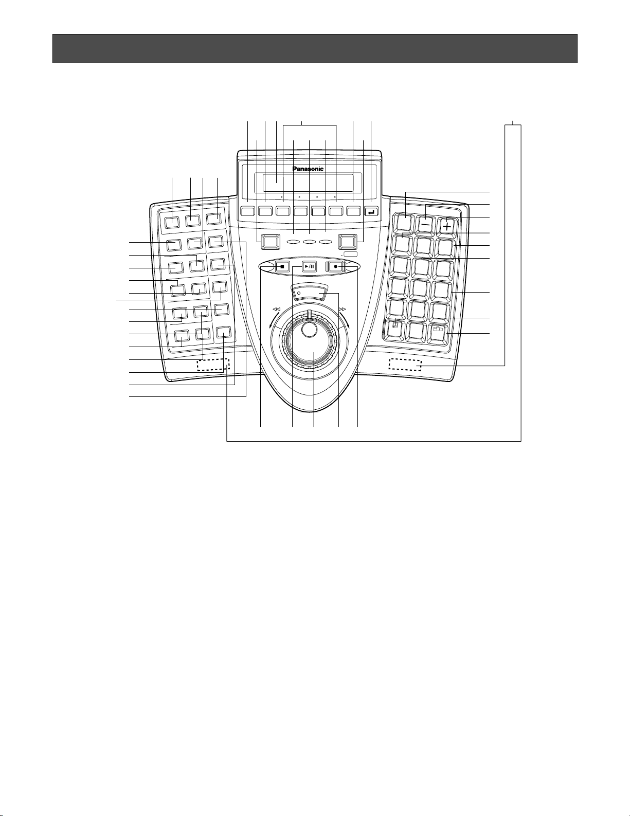
q Operation indicator (OPERATE)
This indicator is lighting while power is supplied to the
system controller.
w Alarm indicator (ALARM)
This indicator blinks when an alarm is activated.
Blinking changes to steady light when the alarm is automatically reset.
e Alarm suspend indicator (ALM SUSPEND)
This indicator lights up when an alarm is suspended.
r Shift button (SHIFT)
To activate the alternate function of each button, press
this button in combination with buttons associated with
special functions.
t Clear button (CLEAR)
Clears the parameter entered with numeric buttons.
y Alarm reset/Alarm all reset button (ALM RESET/
ALM ALL RESET)
• In the PS·Data mode, this button cancels (resets) all the
alarm inputs at a time.
• In the terminal mode, this button cancels (resets) a
selected alarm input.
• In the terminal mode, when you press while holding
down the SHIFT button, this button cancels (resets) all
the alarm inputs at a time.
Note: ALM ALL RESET is reserved for future use.
u Alarm Acknowledge button (ACK)
This button acknowledges a selected alarm input, and
manual operation of alarm-related camera becomes
available.
Note: In the PS·Data mode, this function is reserved for
future use.
i Alarm/Alarm suspend button (ALARM/ALM
SUSPEND)
• When you press while holding down the SHIFT button,
this button temporarily stops alarm inputs to all the system units. When an alarm is suspended, "ALM SUSPEND" indicator lights up.
CLEAR
OPERATE
ADJUST
MENU F1 F2 F3 F4 EXIT ENTER
ALARM
PLAY/PAUSE
SHUTTLE
HOLD
STOP
REV FWD
REC STOP
REC
ALARM
ALM RESET
ACK
ALM SUSPEND
ALM ALL RESET
OSD
CAM FUNC
ALM RECALL
SEQ PAUSE
MON LOCK
TOUR SEQ
MULTI SCREEN
GO TO LAST
EL-ZOOM
AUX1 ON
MARK
AUX2 ON
OFF
OFF
WIPER
SEARCH
DEF ON
OFF
T&D SEARCH
SEQ STOP
LOGOUT
GROUP SEQ
SYS FUNC
1
3
HISTORY
RECORDER
PRESET
PGM
PRESET
CAM
POSI
CAM
(SET)
MON
(ESC)
UNIT
2
4
6
5
7
9
8
0
ALM
SUSPEND
SHIFT
+—
SYSTEM CONTROLLER
WV-CU950
y!0i u
!3
q w ert
$4
#8$0 $33$2#9 $1
@4
!1
#2
#4
#3
#5
#6
#7
#1
#0
@9
!7
!6
!5
!8
!9
@3
@0
@2
@1
@6 @8@8@5 @8@7
!2
o
!4
(This is the illustration of WV-CU950.)
Page 11

11
• When you press after entering numeric buttons, this
button selects an alarm input.
Note: This function is available only when the system
controller is connected to System 850 Matrix
Switcher.
o Camera function/System function button
(CAM FUNC/SYS FUNC)
• Recalls a function of camera by the function number.
• When you press while holding down the SHIFT button,
this button recalls a function of external system unit by
the function number.
Note: This function is available only in the PS·Data
mode.
!0 Alarm recall button (ALM RECALL)
Displays the log of alarms activated in the past.
!1 On-screen display button (OSD)
Toggles the display items on the active monitor.
!2 Monitor lock/Logout button (MON LOCK/LOGOUT)
• Every time you press, this button activates and deactivates monitor lock.
• When you press while holding down the SHIFT button,
you can log out of the system.
!3 Tour sequence/Group sequence button
(TOUR SEQ/GROUP SEQ)
• Runs an assigned tour sequence on a selected monitor
for the specified duration.
• When you press while holding down the SHIFT button,
this button runs an assigned group sequence.
!4 Sequence pause/Sequence stop button
(SEQ PAUSE/SEQ STOP)
• Pauses a sequence.
• When you press while holding down the SHIFT button,
this button stops a sequence.
!5 Go to last button (GO TO LAST)
Plays back the latest recorded image.
!6 Electronic zoom button (EL-ZOOM)
Enlarges an image presently displayed on an active
monitor.
!7 Multiscreen selection button (MULTI SCREEN)
Divides a monitor screen in multiscreen segments to
display camera images simultaneously. Every pressing
this button can change multiscreen segment patterns.
(The available patterns differ depending on recorders.)
!8 Mark button (MARK)
When you press this button during playback, playback
start point will be marked. You can start playback at the
start point. (Refer to the operating instructions of
recorder.)
Note: This button is available only for Digital Disk
Recorder WJ-HD300 Series.
!9 Auxiliary 2 ON/OFF button (AUX 2 ON/OFF)
• Turns on an auxiliary device (AUX 2).
• When you press while holding down the SHIFT button,
this button turns off the auxiliary device (AUX 2).
@0 Auxiliary 1 ON/OFF button (AUX 1 ON/OFF)
• Turns on an auxiliary device (AUX 1).
• When you press while holding down the SHIFT button,
this button turns off the auxiliary device (AUX 1).
@1 Search/Time and date search button (SEARCH/
T&D SEARCH)
• Activates search functions of recorders.
• When you press this button while holding down the
SHIFT button, the date and time appears on the LCD for
time & date search playback.
@2 Defroster button (DEF ON/OFF)
• Turns on a defroster of camera housing .
• When you press while holding down the SHIFT button,
this button turns off the defroster.
@3 Wiper button (WIPER)
Turns on or off a wiper of camera housing.
@4 Stop button (STOP)
Stops the playback of recorded images.
@5 Play/Pause button (PLAY/PAUSE)
• Starts the search playback of recorded images.
• When pressed during playback, this button pauses the
playback.
@6 Recording button (REC)
• Pressing this button starts recording by a recorder.
• Pressing this button for two seconds stops the recording.
@7 Shuttle ring (Outside)/JogDial (Inside)
Shuttle ring:
• When rotated to the right, the playback image is
fast-forwarded. (Fast-forward)
• When rotated to the left, the image is rewound. (The
playback speed differs depending on recorders.)
(Fast reverse)
• Moves the cursor to the next or previous item on the
LCD.
• Moves to the next or previous main item on the
function list.
JogDial:
• Plays back recorded images frame by frame when
this dial is rotated during playback pause. (Single
frame skip)
• When rotated to the right, playback will be skipped
to the next record. When there is no newer record,
normal playback will be continued. (Skip)
Page 12

12
• When rotated to the left, playback will be skipped to
the previous record. When there is no former
record, normal playback will be continued. (Skip)
• Selects a parameter setting or a character on setup
menus.
• Moves to the next or previous sub item on the function list.
@8 Shuttle hold button (SHUTTLE HOLD)
• If you press this button while rotating the shuttle ring,
playback speed will be maintained even after removing
a hand from the shuttle ring. (The LED indicator on this
button blinks during the fast playback.)
Note: This operation differs from “Hold playback
speed” performed by holding the shuttle ring of
recorder. When you hold the playback speed from
the system controller, the EL-ZOOM, MULTISCREEN, and OSD buttons are unavailable.
• If you press this button again, normal playback speed
is recovered.
@9 History button (HISTORY)
When you press the + or – button while holding down
this button, camera images selected in the past are displayed in order or in reverse order.
#0 – button (–)
This button is pressed when selecting a camera with
the lower channel number. During setup, this button is
pressed to decrease the value of selected parameter.
#1 + button (+)
This button is pressed when selecting a camera with
the higher channel number. During setup, this button is
pressed to increase the value of selected parameter.
#2 Recorder/Unit Selection button (RECORDER/UNIT)
• Selects a recorder.
• When you press while holding down the SHIFT button,
this button selects a system unit.
#3 Preset/Program preset button (PRESET/PGM
PRESET)
• Recalls a preset position or the home position of combination camera.
• When you press while holding down the SHIFT button,
this button programs preset positions.
#4 Camera position button (CAM POSI)
This button is pressed to select the camera position
(the combination of camera number and preset position).
#5 Numeric buttons (0, 1 to 9)
Enters camera numbers, monitor numbers, or unit numbers, etc.
#6 Monitor/Escape button (MON (ESC))
• Selects a monitor.
• When pressed during setup, this button determines the
current selection to return to the main menu.
#7 Camera/Set button (CAM (SET))
• Selects a camera.
• When pressed during setup, this button selects an item
to go to a submenu.
#8 LCD (Liquid Crystal Display)
Displays the numbers of unit, monitor and camera currently selected. The LCD also displays the functions
assigned to F1 to F8 buttons.
#9 Adjustment button (ADJUST)
This button is pressed to perform the settings of LCD
brightness, LCD contrast, alarm buzzer, or button
buzzer.
$0 Menu button (MENU)
• Displays the list of menu functions on the LCD.
• Menu functions are assignable to the function buttons
(F1 to F4/F5 to F8) or joystick function buttons (A, B,
and top buttons).
Note: This function is available only in the PS·Data
mode.
$1 Function buttons (F1 to F4/F5 to F8)
• In the PS·Data mode, this button recalls functions you
have assigned.
• In the PS·Data mode, when you press while holding
down the SHIFT button, the F1 to F4 buttons become F5
to F8.
• In the terminal mode, this button activates a function
displayed on the LCD.
$2 Exit button (EXIT)
While a menu function, determined with the ENTER button, is being displayed on the LCD, this button is
pressed to return to the upper menu.
$3 Enter button (ENTER)
While menu functions are displayed on the LCD, this
button determines the menu selection, and displays the
submenu on the LCD.
$4 Feet
When extending these feet, you can raise the front side
by approx. 1 cm {0.39 in.}.
Page 13
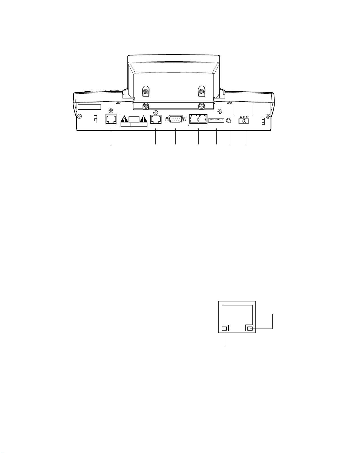
13
● Rear View
$5 Joystick connector (JOYSTICK)
This connector is used for connection with the joystick.
$6 Serial port (SERIAL)
This port is used for connection with a PC for system
configuration.
$7 Data ports (DATA)
• These ports are used for connection with the system
controller and other system units via RS-485 communication.
• These ports used when adding other system controller
connections.
$8 Mode Selection switches (MODE)
The operation mode of system controller is selected
with these switches. (Refer to p. 24 for the setting.)
$9 Controller Number switch (CONTROLLER NO.)
When two or more system controllers are connected in
the system, this switch determines the unit number of
each controller. (Refer to p. 25 for the setting.) If connecting only one system controller in the system, set
this switch to “1”.
%0 DC 9 V Input jack (DC9V IN)
An AC adapter, supplied with the system controller, is
plugged into this jack.
%1 10/100 Base-T port (10/100 BASE-T) (WV-CU950
only)
This port is used for connection with Central Processing
Unit WJ-MPU955/855/850 via an Ethernet network.
LINK indicator: This indicator lights up when the
system controller is linked to a network through this
port.
ACT indicator: This indicator lights up when the
system controller receives or sends data through
this port.
10/100 BASE-T
CAUTION
ATTENTION
JOYSTICK
SERIAL
DATA
MODE
CONTOROLLER
NO.
CAUTION-
CONNECT TO
SPECIFED CLASS 2 POWER
SUPPLY ONLY. SEE MANUAL
DC9V IN
%1
$9 %0$8$7$6$5
(This is the illustration of WV-CU950.)
LINK indicator
ACT indicator
Page 14
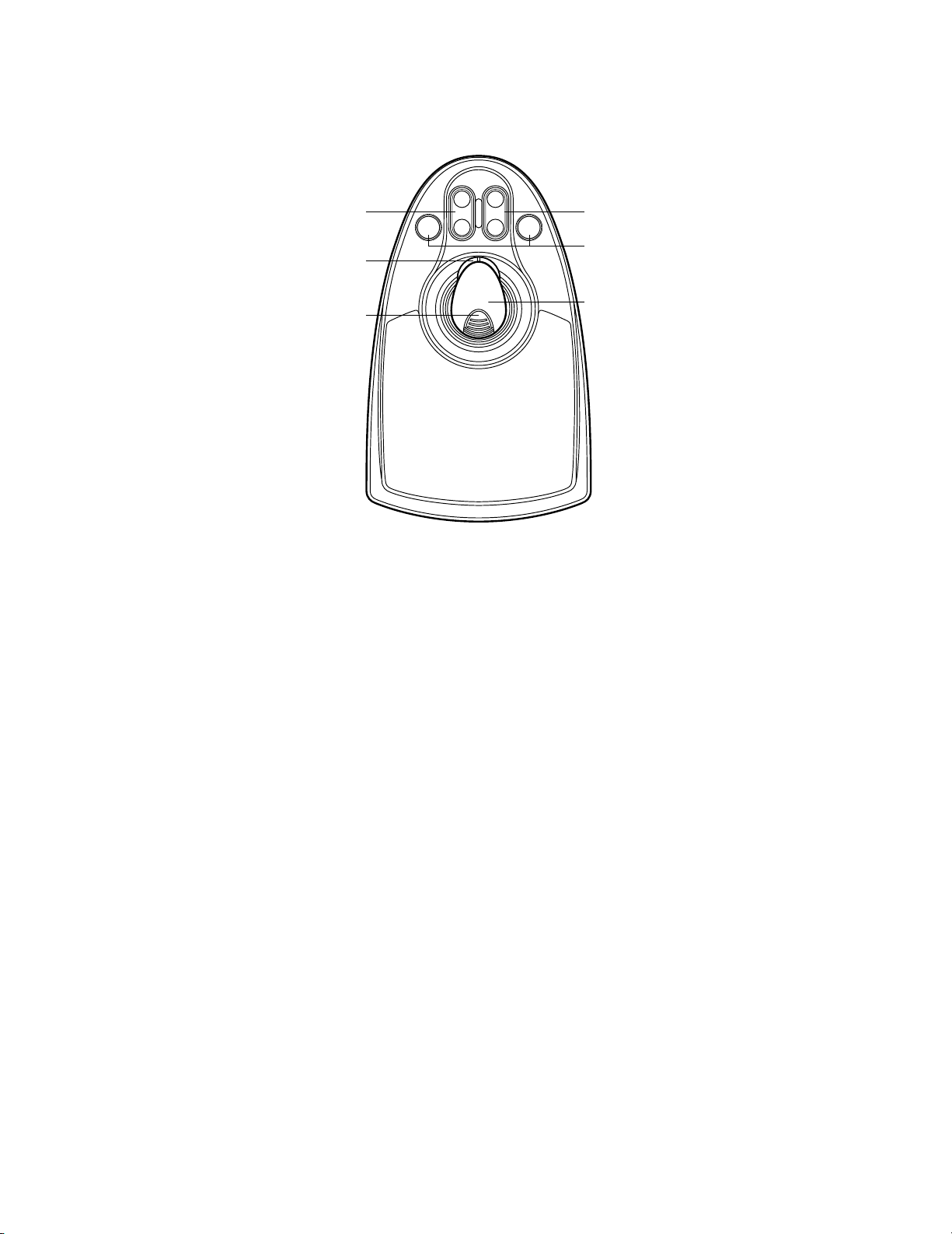
14
%2 Top button
The top button is pressed to recall a function already
assigned.
%3 Zoom wheel controller
This controller is used for zooming cameras equipped
with specific lenses.
%4 Iris control buttons (IRIS CLOSE, OPEN)
These buttons close or open the lens iris of cameras
equipped with specific lenses.
%5 Focus control buttons (FOCUS NEAR, FAR)
These buttons adjust the lens focus of cameras
equipped with specific lenses.
%6 A and B buttons (A, B)
These buttons recall functions you assign.
%7 3D joystick
Controls the panning and tilting of combination cameras and pan/tilt heads.
■ 3D Joystick Unit
This joystick unit is used to operate combination cameras and pan/tilt heads manually.
OPEN
FAR
IRIS
%4 %5
A B
%3
CLOSE
FOCUS
NEAR
%6
%2
%7
Page 15
15
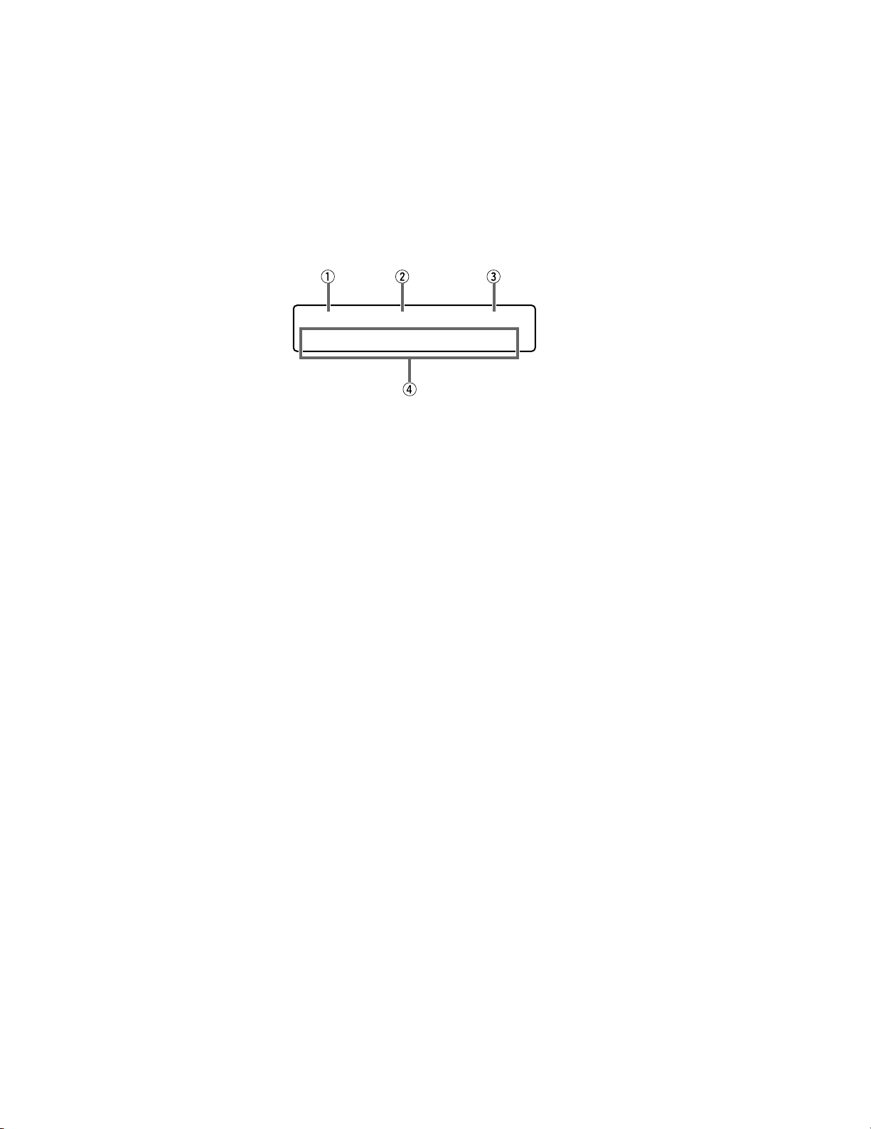
■ LCD Display Descriptions
The following are examples of LCD display after login in the PS·Data mode.
Notes:
• Some parts of LCD displays, described on this document, may differ from the actual status.
• Refer to the operating instructions of connected devices for details on LCD display in modes other than PS·Data.
● Default Status (LCD Display After Login)
q Monitor number
The number of selected monitor is displayed. 1 to 99
can be displayed as a monitor number.
w Camera number
• The number of selected camera is displayed. 1 to 999
can be displayed as a camera number.
• When a camera position is specified, the camera position number is displayed.
• When a sequence is activated on the selected monitor,
"Seq" is displayed.
e Model number/Unit number
• The model number of connected system unit is displayed. When you select a system unit, the unit number
of connected system unit is displayed. The following
are examples of model number display.
"HD500": Digital Disk Recorder WJ-HD500 Series
"SX150A": Matrix Switcher WJ-SX150A
Notes:
• The model number is abbreviated when an actual
model number exceeds 6 characters.
• When you have selected a monitor supporting
PS·Data (WV-CM2080, WV-CM1780, or WVCM1480), the model number displayed on the LCD
is "CM2080".
• When you press the RECORDER/UNIT button, the unit
number of connected system unit appears. 1 to 99 can
be displayed as a unit number.
• Numerics you have entered are displayed on this area.
r Function number (F1 to F8)/LCD title
• In the factory default, function numbers “F1” to “F4” are
displayed. “F5” to “F8” are displayed while holding
down the SHIFT button.
• The LCD titles, assigned to function buttons (F1 to
F4/F5 to F8), can also be displayed. You can edit the
function names in up to 20 alphanumeric characters.
You can display F5 to F8 function names while holding
down the SHIFT button.
Mon02 Cam016 HD316
F1 F2 F3 F4
Page 16
16
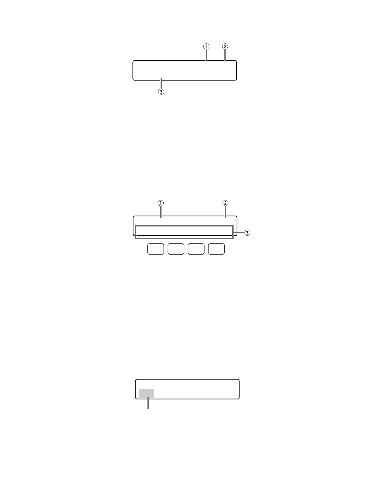
● Main Menu (Menu Functions)
q Category
The category of selected menu function is displayed.
w Function number
The function number of selected menu function is displayed.
Note: Refer to p. 58 Menu Function Categories.
e Function name
The name of selected menu function is displayed.
● Sub Menu (Menu Functions)
q Function name
The name of selected menu function is displayed.
w Function number
The function number of selected menu function is displayed.
e Button actions
The actions activated by the function (F1 to F4) buttons
are displayed. When pressed while holding down the
SHIFT button, actions of F5 to F8 buttons are displayed.
Note: When the selected button function has no button
actions, nothing is displayed on this area.
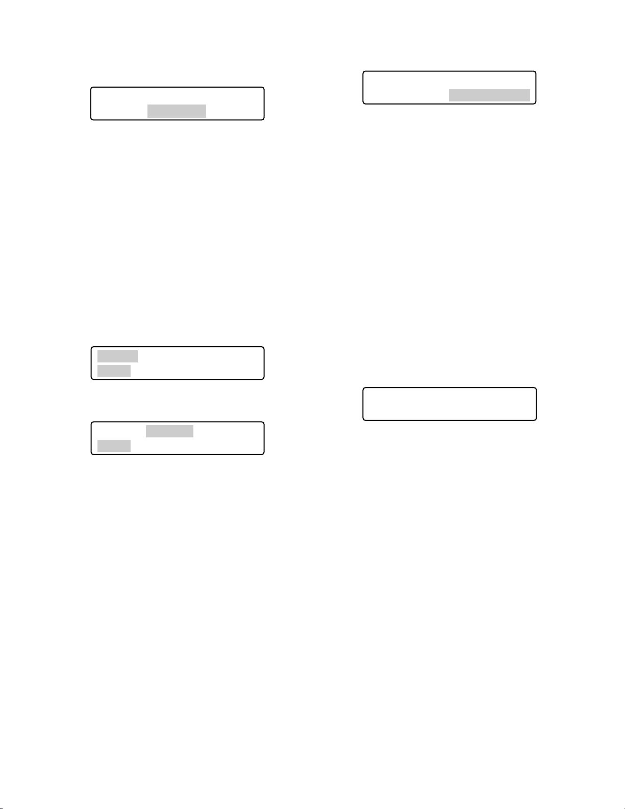
● Blinking
In this document, grayed areas on the illustrations mean blinking.
LCD MENU CAM 101
Camera Setup
Camera Setup 101
On Off Rst A.Rst
F1 F2 F3 F4
Mmm/DD/YYYY HH:MM 12
Mar/17/2004 12:00 AM
Blinking
Page 17
17
● Messages Displayed on the LCD
Invalid
This message is displayed in the following circumstances.
• When you have entered a wrong user ID or password,
etc.
• When you have entered a camera number or menu
number, etc. that is not existing.
Busy
• When a selected monitor is controlled by a higher-level
user, the monitor number and “Busy” blinks on the LCD.
(You cannot control the monitor.)
• When a selected camera is controlled by a higher-level
user, the camera number and “Busy” blinks on the
LCD. (You cannot control the camera.)
• To cancel the Busy status, select another monitor, or
wait until “Busy” goes out.
Prohibited
• When you have tried an operation not authorized by the
function level setting, camera level setting, or selected
system unit, “Prohibited” blinks on the LCD.
• When you have forgotten to select a system unit or
monitor before selecting a camera, “Prohibited” blinks
on the LCD.
• When you have selected a system unit disconnected
from the system, “Prohibited” blinks on the LCD.
• After a few seconds, the LCD display will return to the
default status.
Notes:
• After a few seconds, this message will automatically
disappear.
• The illustration is an example in which a camera number other than 1 to 256 has been entered.
• In this document, gray area on illustration shows blinking.
Controller No.1 No Exist Error
This message is displayed when no system controller is set
to CONTROLLER NO.1. Check that a system controller is
set to CONTROLLER NO. 1 (Refer to p. 25 CONTROLLER
NO. Switch Setting.)
Invalid
Mon02 Cam016 HD316
Prohibited
Mon02 Cam016 HD316
Busy
"Busy" status is activated for a monitor.
Mon02 Cam016 HD316
Busy
"Busy" status is activated for a camera.
Controller No.1
No Exist Error
Page 18

18
Page 19

19
INSTALLATIONS AND SYSTEM
CONNECTIONS
Page 20
20
INSTALLATIONS AND CONNECTIONS
WARNING
The installations described in the figures should be made by qualified service personnel or system installers.
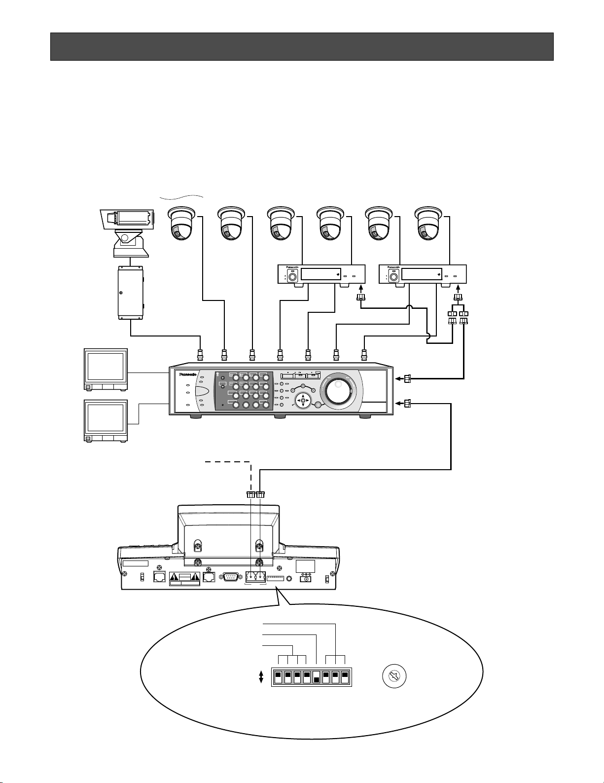
■ Basic System Connections
The following is an example in which a recorder and data multiplex units are connected.
Note: The connection example shown in this document is available in the PS·Data mode. When applying connections in a
mode other than PS·Data, refer to the operating instructions of connected devices.
System Controller
WV-CU950/650
(Main unit)
Modular cable (supplied)
Used when adding other WV-CU950/650
system controllers (Available up to 3)
To P S ·Data ports
0
9
8
7
6
5
4
3
2
1
Fixed
PS·Data Mode
Line termination: ON
Refer to pp. 24 and 25 for details on settings.
CONTROLLER NO.: 1
MODE
OFF
ON
DC9V IN
MODE
DATA
SERIAL
CONTOROLLER
NO.
JOYSTICK
10/100 BASE-T
CAUTION
ATTENTION
CAUTION-
CONNECT TO
SPECIFED CLASS 2 POWER
SUPPLY ONLY. SEE MANUAL
Camera 8 Camera 91to Camera 12 Camera 13 Camera 16Camera 1
Monitor 1
Monitor 2
• • •
• • •
• • •• • •
• • • • • •• • • • • •
to
41 4
Data Multiplex Unit
WJ-MP204C
(Two units)
Unit Address: 2 and 3
Daisy Chain
Connection Kit
WV-CA48/10K
PS·Data
PS·Data
198121613
• • •
• • •
• • •
14
• • •
14
14
7
8
9
11 12
13 14 15 16
10/0
526
3
Digital Disk Recorder WJ-HD300 Series
Unit Address (System) : 1
Unit Address (Controller) : 2
Line termination: OFF
POWER
ON
OFF
ALARM
Data Multiplex Unit WJ-MP204
ALARM
SUSPEND
1234
ESCSET
RESET
SUSPEND SET UP
ALARM
UNIT
0
9
8
7
6
5
4
3
2
1
POWER
ON
OFF
ALARM
Data Multiplex Unit WJ-MP204
ALARM
SUSPEND
1234
ESCSET
RESET
SUSPEND SET UP
ALARM
UNIT
0
9
8
7
6
5
4
3
2
1
Page 21
21
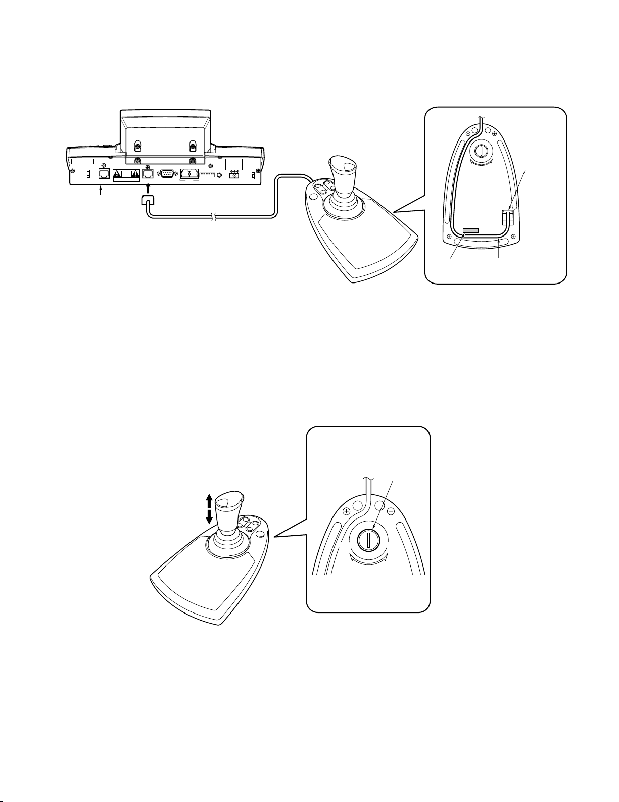
■ Connection with the 3D Joystick Unit
Connect the main unit and 3D joystick unit as follows.
Note: Use the main unit and 3D joystick unit whose combination codes are identical.
■ Adjustment of 3D Joystick
To adjust the altitude of 3D joystick, turn the adjusting screw to the right or left.
Main unit
3D joystick unit
CONNECT TO
CAUTION-
SPECIFED CLASS 2 POWER
CAUTION
ATTENTION
10/100 BASE-T
Combination code label
has been stuck
on the bottom.
JOYSTICK
SERIAL
DATA
Cable (supplied)
SUPPLY ONLY. SEE MANUAL
CONTOROLLER
MODE
DC9V IN
NO.
Bottom side
UP
DOWN
Cable
connector
Bottom side
Adjusting
Up
Down
screw
Combination
code label
Fit the cable
into the cable trench.
DOWN
UP
Page 22

22
Page 23

23
WV-CU950/650 SETUP
PROCEDURES
Page 24
24
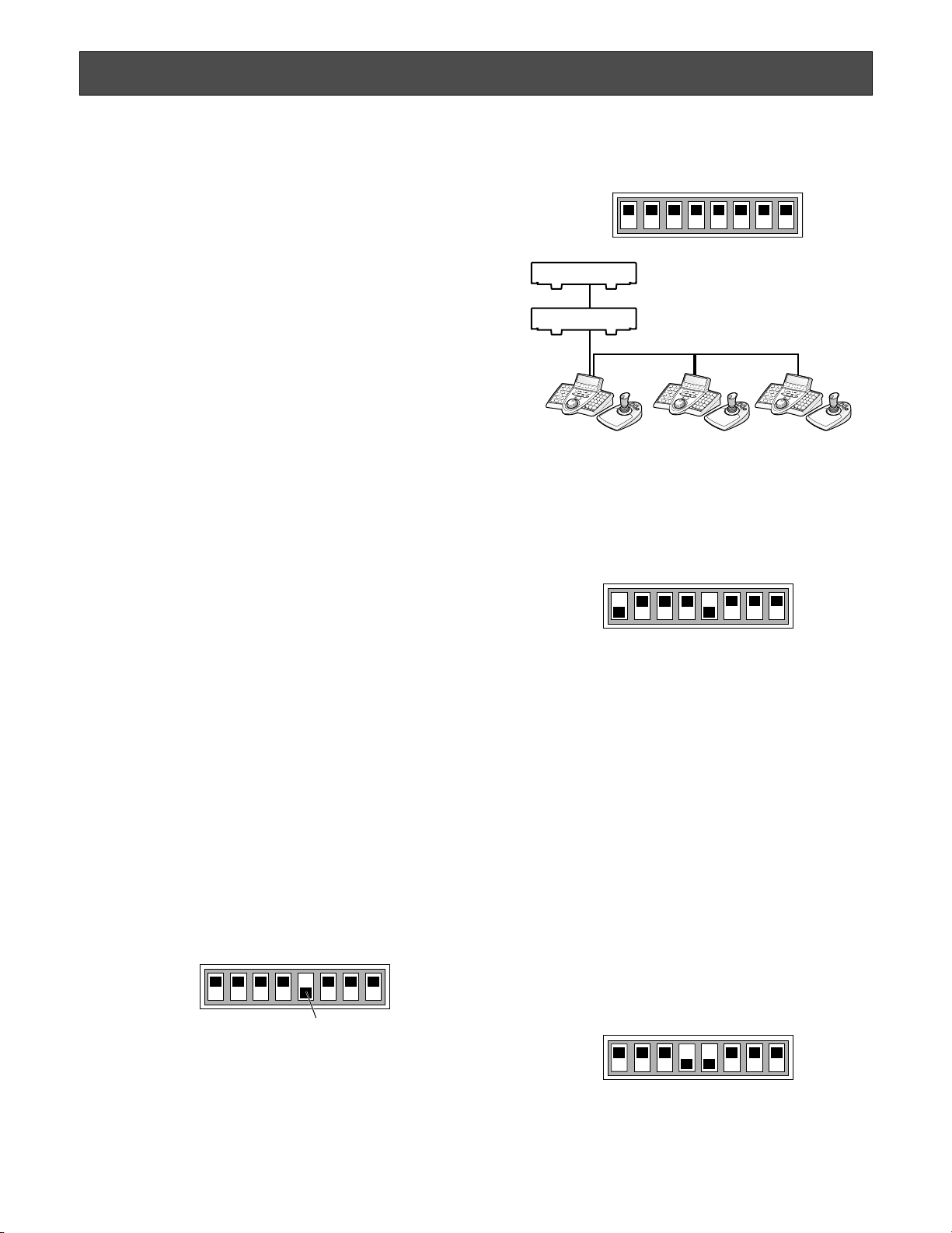
2. Set the Line termination switch of other system controllers to OFF.
● Setting for Terminal Mode
Set the MODE Switch #1 and #5 to ON.
Note: Refer to the operating instructions of connected
devices for details on connections and operations.
● Setting for Connection with Central
Processing Unit
(WJ-MPU955 Series/WJ-MPU855 Series/
WJ-MPU850 Series)
Terminal mode
Note: Refer to "Setting for Terminal Mode" in this page for
the switch setting.)
Ethernet mode
To apply this mode, set the MODE Switch #4 and #5 to ON.
Note: Refer to the operating instructions of connected
devices for details on connections and operations.
SETUP PROCEDURES (HARDWARE)
■ Setup Procedures
Perform the setup as follows.
1. Set the MODE switches.
You will set up the communication mode and line termination ON/OFF of RS-485 communication. (Refer to
MODE Switch Setting.)
2. Set CONTROLLER NO. switches.
You will perform this setting when using two or more
system controllers in daisy chain connections. (Refer to
p. 25 CONTROLLER NO. Switch Setting.)
3. Perform WV-CU650 setups after entering the administrator password.
You will perform the settings concerning password and
communication between system controllers and other
system units, etc. (Refer to p. 26.)
Note: Before performing WV-CU950/650 setups, you need
to log into the system by entering the administrator
password. (Refer to p. 26.)
■ MODE Switch Setting
You will perform the setting of the MODE switches at the
rear panel.
Notes:
• Before the setting, turn off the system controller. (Refer
to p. 36 Power-off.)
• Do not move the MODE switches to positions other than
described in these illustrations. That may cause malfunction.
● Setting for PS·Data Mode
If using only one system controller
Set the MODE Switch #5 to ON.
If using two or more system controllers in
daisy chain connections
1. Set the MODE Switch #5 of the system controller at the
chain end to ON.
1234 567 8
OFF
ON
System units
Line termination ON
Line termination OFF
Line termination OFF Line termination OFF Line termination ON
1234 567 8
OFF
ON
1234 567 8
OFF
ON
MODE Switch #5 (Line termination switch)
1234 567 8
OFF
ON
Page 25

25
Notes:
•“0” and “9” are reserved numbers. They cannot be set
for controller numbers.
• One of the system controllers must be set to "1".
• To connect Digital Disk Recorder WJ-HD300 Series to
system controllers, the Unit Address (Controller) setting
must be different from each CONTROLLER NO. switch
setting. (Refer to the operating instructions of recorder
for details on the setting.)
● Setting for Connection with Central
Processing Unit
(WJ-MPU955 Series/WJ-MPU855 Series/
WJ-MPU850 Series)
Maintain the switch setting as “1 (factory default position)”.
■ CONTROLLER NO. Switch Setting
You will determine controller-number settings by moving
the CONTROLLER NO. switch at the rear panel.
● Setting for PS·Data/Terminal Mode
If using only one system controller
Maintain the switch setting as “1 (factory default position)”.
If using two or more system controllers in
daisy chain connections
Up to 4 system controllers are connectable in the system.
To avoid conflict, set the unique number for each system
controller.
0
1
9
2
8
3
7
4
6
5
CONTROLLER NO.
Page 26
26
SETUP PROCEDURES (FIRMWARE)
■ Administrator Password Entry
If you log into the system in the administrator mode,
PS·Data communication setting, all reset, operator password check. and database copy will become available.
To activate the administrator mode, you need to enter the
administrator password.
Notes:
• The factory default of administrator password is “650”.
However, for security, you should change the password
setting. To change the setting, refer to p. 31.
• Take a note of your administrator password.
■ Setting Modes
If you power on the system controller while pressing the following buttons, the system will run in an associated setting
mode.
Notes:
• You cannot change the system from the following
modes (refer to the diagram) to the normal operation
mode. To start up the normal operation mode, turn off
the system controller, and then turn on the controller
again.
• The administrator password entry is required for the following modes.
* The panning, tilting, and zooming calibration settings are
not restored.
■ All Reset
When the all reset mode is activated, all of the following settings will be reset to the factory default.
• Administrator password
• PS·Data communication setting
• LCD brightness, contrast, alarm buzzer, and button
buzzer settings
• Button functions and joystick button functions (F1 to F8,
A, B, and top buttons)
• Controller functions
(Time & Date Type)
(Auto Login)
(Operator Setup)
(Function Level)
(Camera Level)
(Cam Posi Map)
(Cam-Unit Map)
(HDD-Unit Map)
(LCD Title)
Note: Calibration settings of panning, tilting, and zooming
will be maintained even after all reset.
Buttons pressed
while
the power-on
2, 4, and 6
MON (ESC) and 6
MON (ESC) and 1 Administrator
password change
The administrator
password can be
changed.
Setting Mode
All reset
PS·Data
Communication
setting
Description
The communication
settings and
PS·Data database
can be restored to
the factory default.*
PS·Data communication setting can
be performed.
MON (ESC) and 2
MON (ESC) and 4
PS·Data database
copy
PS·Data password
display
The PS·Data database can be copied
from the source
system controller
(Controller No. 1) to
a destination system controller.
The passwords of
up to 16 operators
can be displayed
on the LCD.
Page 27
27
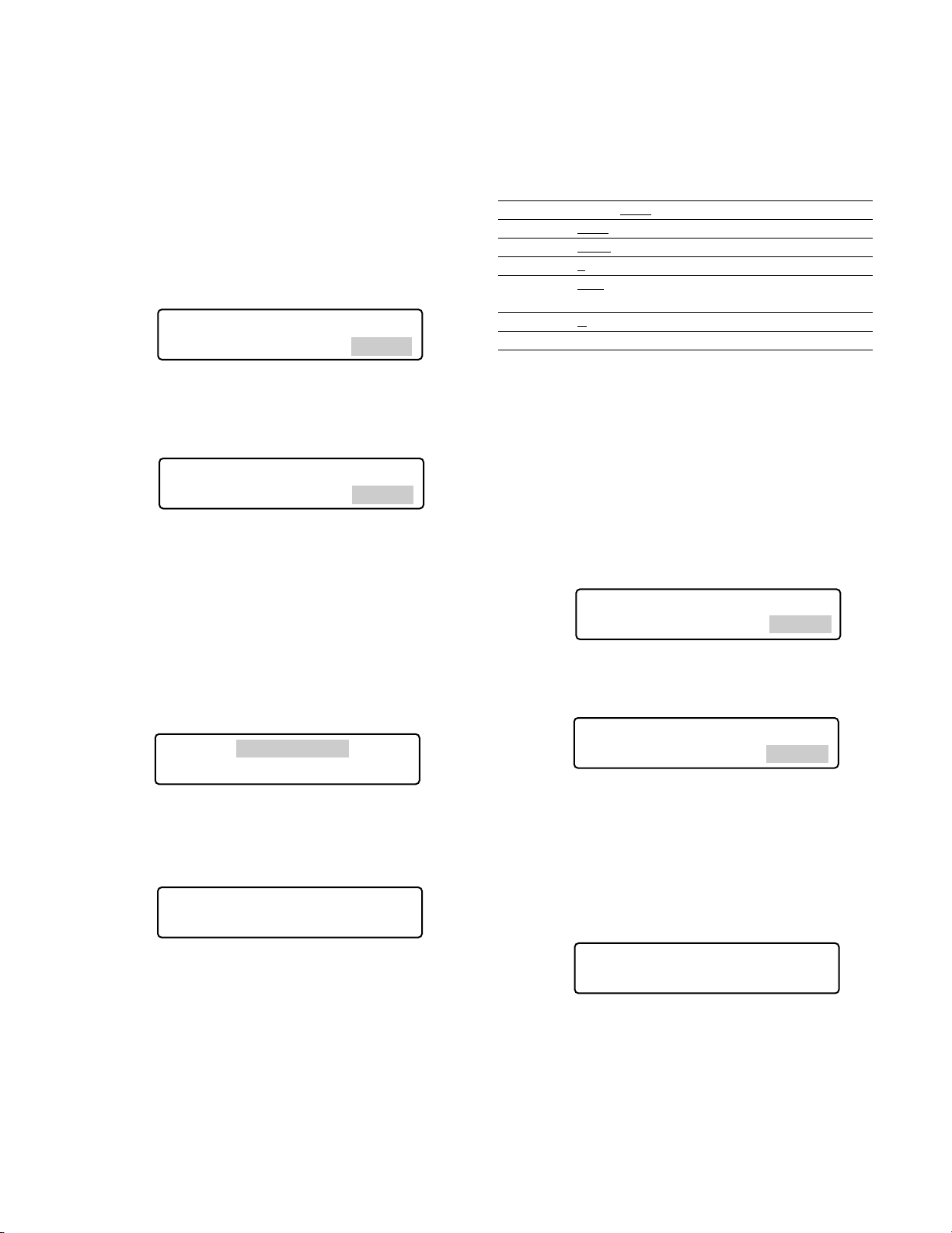
● Operation
1. Turn off the power.
Note: If you set the MODE Switch #1 to #4 to ON, you
can skip entering the administrator password in
Step 3.
2. Turn on the power while holding down the buttons 2, 4,
and 6.
“Admin Password” will appear on the LCD to enter the
password.
3. Enter the administrator password.
The password entered will be displayed as “∗” marks.
Notes:
• The factory default is “650”.
• To delete a character, press the CLEAR button.
• If you have entered a wrong password, the LCD
display will return to Step 2.
4. Press the CAM (SET) button.
If the password entered is correct, all the settings will
be reset to the factory default.
5. Check “End” on the LCD.
Check “End” has appeared on the LCD to inform you of
the initialization end.
6. Turn off the power.
■ PS·Data Communication Setting
This setting is required to establish a connection between
the system units and system controller.
List of PS·Data communication settings
Setting Item Available setting parameter(s)
Baud Rate 4800 / 9600 / 19200 bps
Data Bit 8 bit (Fixed)
Parity Bit None
/ Odd / Even
Stop Bit 1
/ 2 bit
Wait Time OFF
/ 100 msec / 200 msec /
400 msec / 1000 msec
Group Adr A
to Z
Xon/Xoff Not Use (Fixed)
Note: Factory defaults are underlined.
● Operation
1. Turn off the power.
2. Turn on the power while holding down the button 6 and
MON (ESC) button.
“Admin Password” will appear on the LCD to enter the
password.
3. Enter the administrator password.
The password entered will be displayed as “∗” marks.
Notes:
• The factory default is “650”.
• To delete a character, press the CLEAR button.
4. Press the CAM (SET) button.
If the password entered is correct, "Baud Rate" setting
form will appear on the LCD.
Notes:
• If the password entered is wrong, “PS·Data Com.
Setup” will appear on the LCD again to reenter the
password.
• You can change the setting item display on the LCD
by rotating the JogDial.
All Reset
Admin Password _____
All Reset
Admin Password ∗∗∗∗∗
•
PS Data Com. Setup
Admin Password _____
All Reset All Reset
All Reset
End
•
PS Data Com. Setup
Admin Password ∗∗∗∗∗
•
PS Data Com. Setup
Baud Rate 9600
Page 28
28
System unit group address
(No need for setup) Remain the factory default.
6. Perform the settings.
Setting procedures differ depends on items. Refer to p.
28 to 30 for how to operate.
7. After you have completed the settings, turn off the
power.
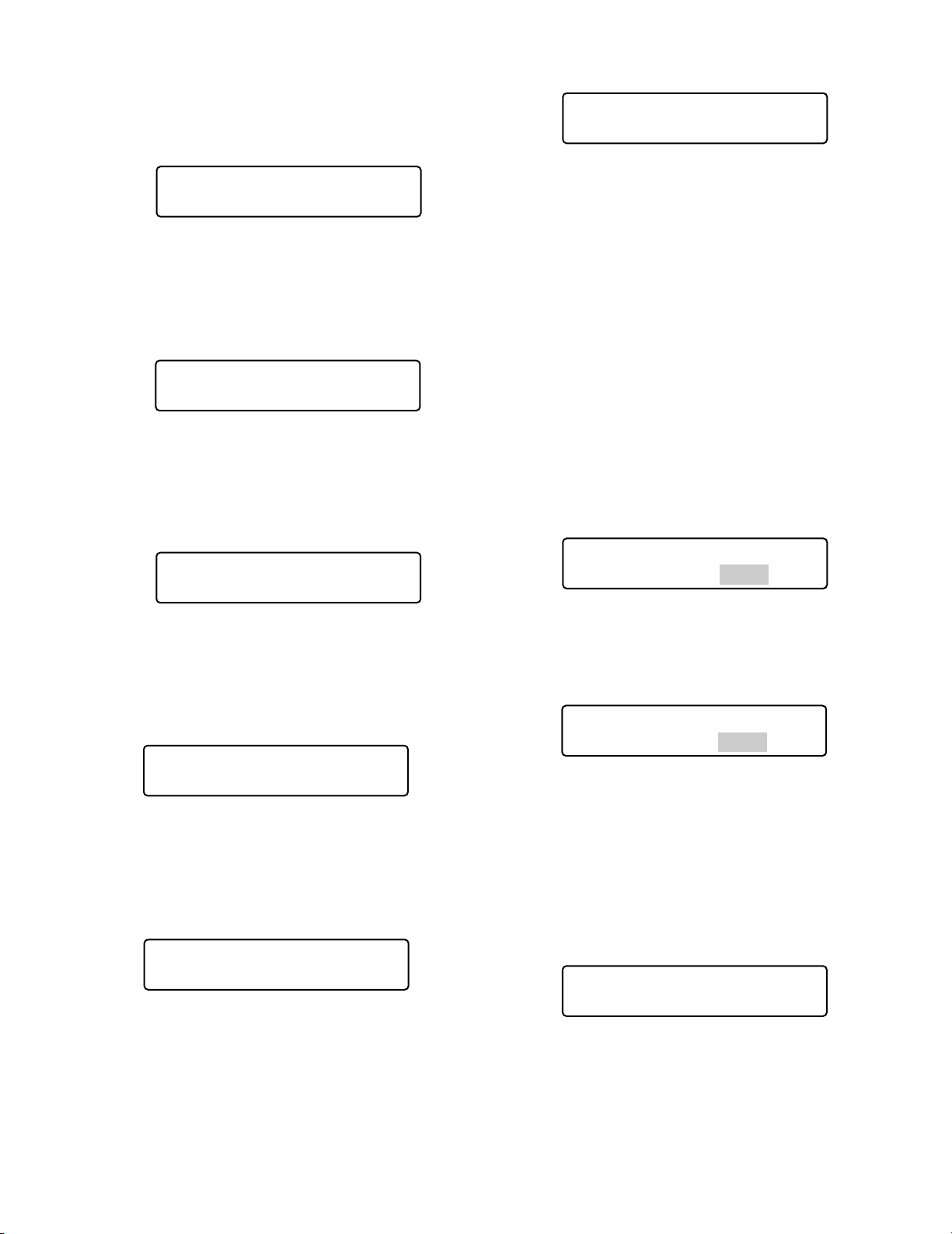
● Baud Rate Setting
1. Select “Baud Rate” by rotating the JogDial.
(Refer to Step 5 in Operation.)
2. Press the CAM (SET) button.
The LCD display will change from the display mode to
the editing mode.
3. Select a desired parameter by rotating the JogDial, or
pressing the + or – button.
You can select the desired parameter from “19200”,
“9600”, and “4800”. The factory default is “9600”.
Note: Conform this parameter to the baud rate of other
system units. Otherwise, communication will not be
established between the system controller and system units.
4. Press the MON (ESC) button.
The selected parameter will be determined, and the
LCD display will return from the editing mode to the display mode.
5. Select an item you wish to set up by rotating the
JogDial.
Baud rate
The speed of communication between the system controller
and other system units
Parity bit
The parity bit, added to the data, to perform parity check
(Refer to p. 29 for details.)
Stop bit
The stop bit, added to the last of data, in asynchronous
communication (Refer to p. 29 for details.)
Wait time
The wait time until the data is sent again (Refer to p. 29 for
details.)
Controller group address
(No need for setup) Remain the factory default.
•
PS Data Com. Setup
Sys G—Adr.
•
PS Data Com. Setup
Baud Rate 9600
•
PS Data Com. Setup
Parity Bit None
•
PS Data Com. Setup
Stop Bit 1
•
PS Data Com. Setup
Baud Rate 9600
•
PS Data Com. Setup
Wait Time Off
•
PS Data Com. Setup
Cnt G—Adr. A
•
PS Data Com. Setup
Baud Rate 4800
•
PS Data Com. Setup
Baud Rate 4800
Page 29
29
4. Press the MON (ESC) button.
The selected parameter will be determined, and the
LCD display will return from the editing mode to the display mode.
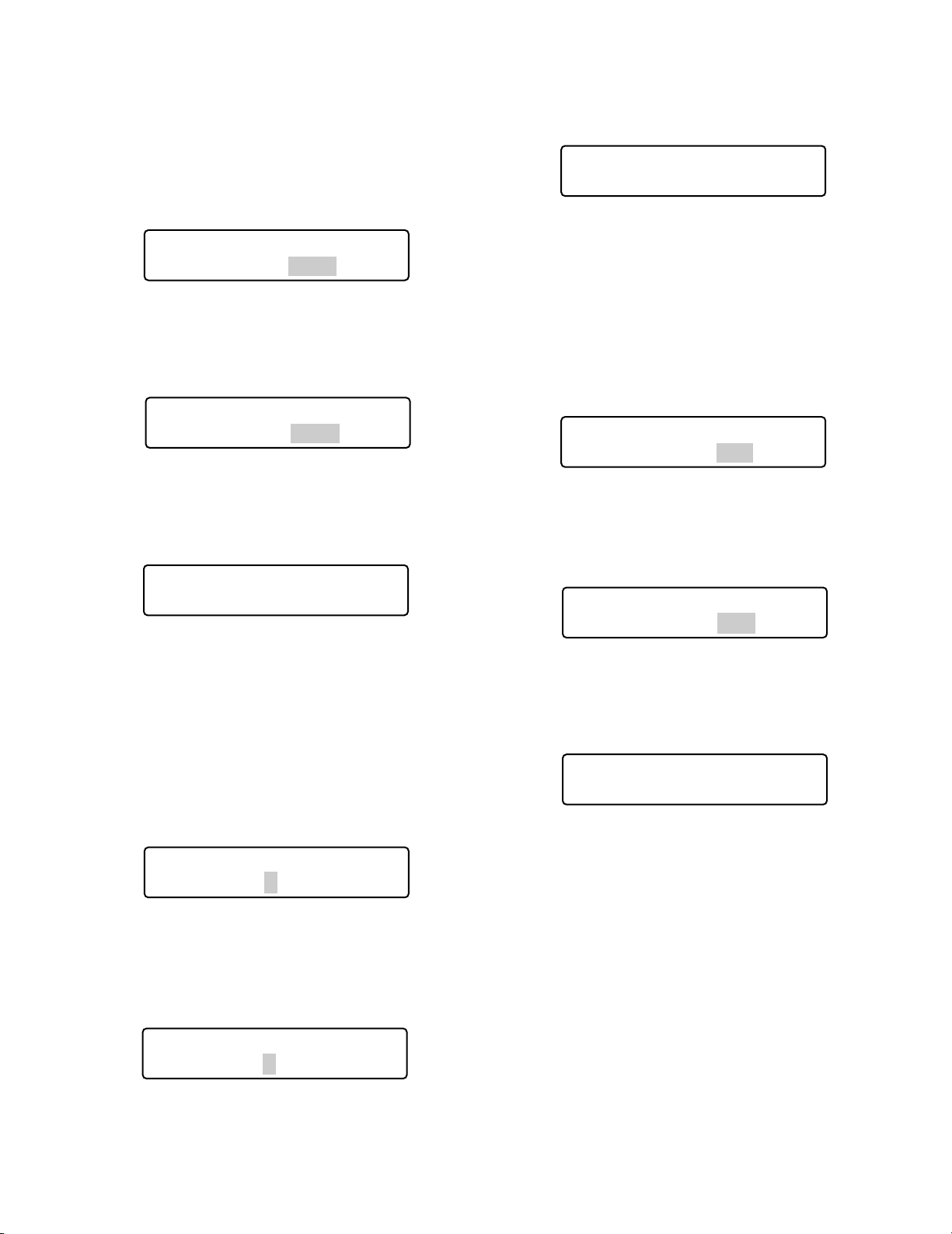
● Wait Time Setting
1. Select “Wait Time” by rotating the JogDial.
(Refer to Step 5 in p. 28 Operation.)
2. Press the CAM (SET) button.
The LCD display will change from the display mode to
the editing mode.
3. Select a desired parameter by rotating the JogDial or
pressing the + or – button.
You can select the desired parameter from “Off”, “100
(msec)”, “200”, “400”, and “1000”.
4. Press the MON (ESC) button.
The LCD display will return from the editing mode to the
display mode, and the selected parameter will be
determined.
● Parity Bit Setting
1. Select “Parity Bit” by rotating the JogDial.
(Refer to Step 5 in p. 28 Operation.)
2. Press the CAM (SET) button.
The LCD display will change from the display mode to
the editing mode.
3. Select a desired parameter by rotating the JogDial or
pressing the + or – button.
You can select the desired parameter from “None”,
“Odd”, and “Even”. The factory default is “None”.
4. Press the MON (ESC) button.
The selected parameter will be determined, and the
LCD display will return from the editing mode to the display mode.
● Stop Bit Setting
1. Select “Stop Bit” by rotating the JogDial.
(Refer to Step 5 in p. 28 Operation.)
2. Press the CAM (SET) button.
The LCD display will change from the display mode to
the editing mode.
3. Select a desired parameter by rotating the JogDial or
pressing the + or – button.
You can select the desired parameter from “1” (bit) and
“2”. The factory default is “1”.
•
•
PS Data Com. Setup
PS Data Com. Setup
Parity Bit None
Parity Bit None
•
PS Data Com. Setup
Parity Bit Even
•
PS Data Com. Setup
Parity Bit Even
•
PS Data Com. Setup
Stop Bit 2
•
PS Data Com. Setup
Wait Time Off
•
PS Data Com. Setup
Wait Time 100
•
PS Data Com. Setup
Stop Bit 1
•
PS Data Com. Setup
Stop Bit 2
•
PS Data Com. Setup
Wait Time 100
Page 30
30
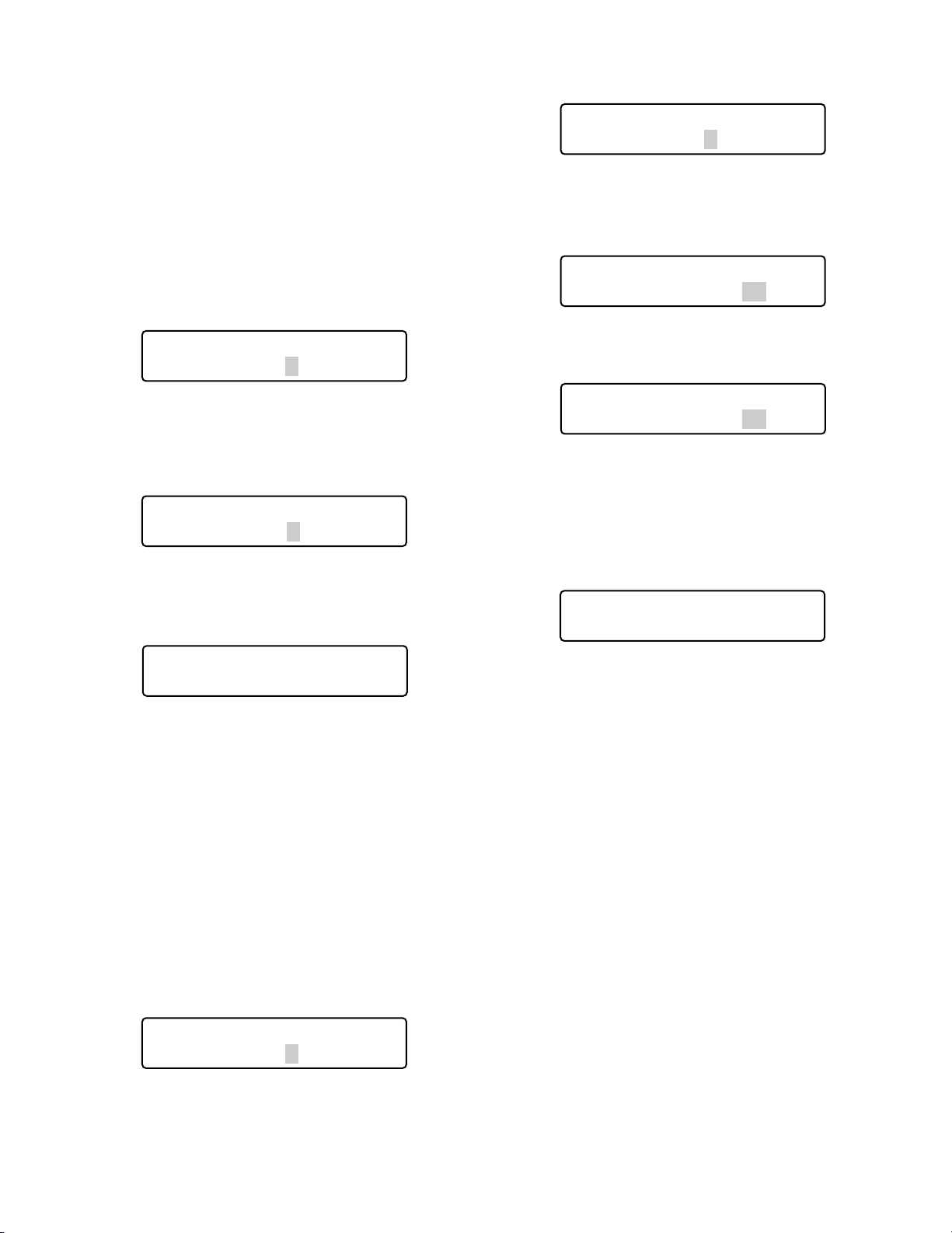
● Group Address Setting for System
Controller
Note: Remain the factory default. When you have mistaken-
ly changed the setting, recover the factory default as
follows.
1. Select “Cnt G-Adr.” by rotating the JogDial.
(Refer to Step 5 in p. 28 Operation.)
2. Press the CAM (SET) button.
The LCD display will change from the display mode to
the editing mode.
3. Select a desired parameter by rotating the JogDial or
pressing the + or – button.
You can select the desired parameter from “A” to “Z”.
The factory default is “A”.
4. Press the MON (ESC) button.
The selected parameter will be determined, and the
LCD display will return to the display mode.
● Group Address Setting for System
Units
Note: Remain the factory default. When you have mistaken-
ly changed the setting, recover the factory default as
follows.
1. Select “Sys G-Adr.” by rotating the JogDial.
(Refer to Step 5 in p. 28 Operation.)
2. Press the CAM (SET) button.
The LCD display will change from the display mode to
the editing mode.
3. Select "A" by rotating the JogDial or pressing the + or –
button.
4. Press the CAM (SET) button.
The parameter will be determined, and the cursor will
jump to the sub parameter.
5. Enter the unit number of system unit by rotating the
JogDial or pressing the + or – button.
Note: 1 to 99 is available for the unit number. The facto-
ry default is 01.
6. Press the CAM (SET) button.
The sub parameter will be determined, and "OK" will
appear on the LCD.
After a second, the LCD display will return to the status
in Step 5.
If you set the unit numbers of other system units, repeat
Step 5.
Note: If the parameters cannot be determined, "NG" will
appear on the LCD. In this case, check the unit
number of system unit, and repeat Step 3 to 6.
7. Press the MON (ESC) button.
The LCD display will return to the status in Step 2.
8. Press the MON (ESC) button again.
The LCD display will return from the editing mode to the
display mode.
•
PS Data Com. Setup
Sys G—Adr. A
•
PS Data Com. Setup
Cnt G—Adr. B
•
PS Data Com. Setup
Cnt G—Adr. A
•
PS Data Com. Setup
Cnt G—Adr. A
•
PS Data Com. Setup
Sys G—Adr. A 05
•
PS Data Com. Setup
Sys G—Adr. A 01
•
PS Data Com. Setup
Sys G—Adr. A 01 OK
•
PS Data Com. Setup
Sys G—Adr. B
Page 31
31
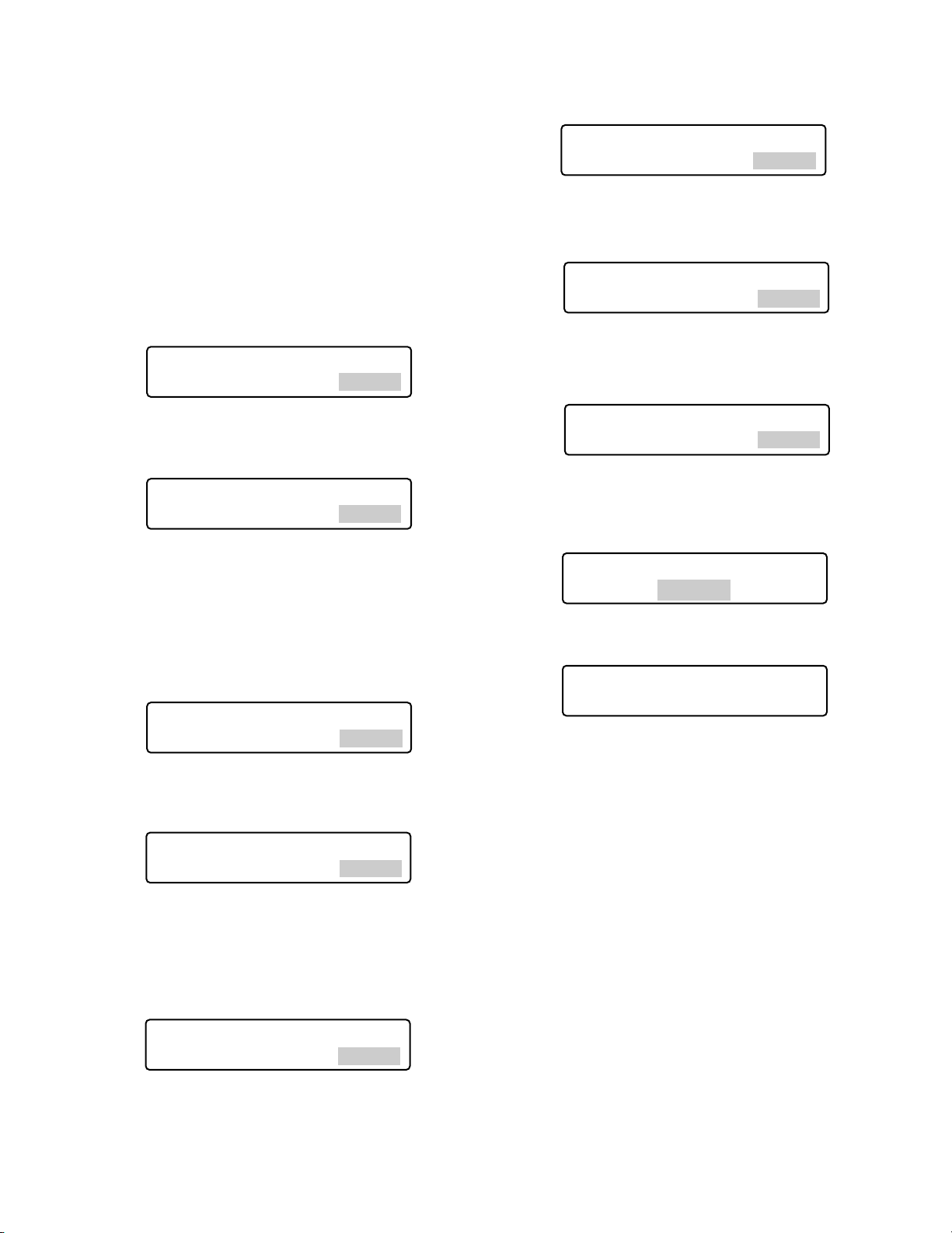
■ To Change the Administrator Password
You can change the administrator password. The factory
default is “650”.
● Operation
1. Turn off the power.
2. Turn on the power while holding down the button 1 and
MON (ESC) button.
“Admin Password” entry form will appear to perform the
setting.
3. Enter the current administrator password.
The password entered will be displayed as “∗” marks.
Notes:
• The factory default is “650”.
• To delete a character, press the CLEAR button.
4. Press the CAM (SET) button.
If the password entered is correct, “Old Password”
entry form will appear.
5. Enter the current administrator password again.
The password entered will be displayed as “∗” marks.
Note: To delete a character, press the CLEAR button.
6. Press the CAM (SET) button.
If the password entered is correct, “New Password”
entry form will appear.
Note: If the old password entered is wrong, the LCD
display will return to Step 4. Enter the old password
again.
7. Enter a new administrator password.
The password entered will be displayed as “∗” marks.
“1” to “99999” are available for the password.
8. Press the CAM (SET) button.
“New Password” entry form will appear again.
9. Enter the new administrator password again.
The password entered will be displayed as “∗” marks.
10. Press the CAM (SET) button.
The new password has been memorized in the system,
and “Memory” will appear on the LCD.
Then, “End” will appear on the LCD.
Note: If the new password entered is wrong, the LCD
display will return to Step 4. Enter the old password
again.
11. Turn off the power.
Admin Password Setup
New Password ∗∗∗∗∗
Admin Password Setup
Admin Password _____
Admin Password Setup
Admin Password ∗∗∗∗∗
Admin Password Setup
Old Password _____
Admin Password Setup
Old Password ∗∗∗∗∗
Admin Password Setup
New Password _____
Admin Password Setup
New Password ∗∗∗∗∗
Admin Password Setup
Memory
Admin Password Setup
End
Admin Password Setup
New Password _____
Page 32
32
■ PS·Data Database Copy
You can copy the database from the source system controller (CONTROLLER NO. switch is set to 1.) to destination
system controllers (CONTROLLER NO. switch is set to 2 to
8.). When using two or more system controllers in the system, you can copy the following settings.
• Administrator password
• Button functions and joystick button functions
(F1 to F8, A, B, and top buttons)
• Controller functions
(Time & Date Type)
(Auto Login)
(Operator Setup)
(Function Level)
(Camera Level)
(Cam Posi Map)
(Cam-Unit Map)
(HDD-Unit Map)
(LCD Title)
Notes:
• Database copy to two or more system controllers is
available at a time.
• To activate this mode, you need to perform the PS·Data
communication settings. (Refer to p. 27 PS·Data
Communication Setting.)
• This function is available only among WV-CU950/650
System Controllers. You cannot copy the PS·Data database to other models, such as WV-CU360C.
• You cannot copy the database from Ver. 2.xx system
controllers to Ver. 1.xx system controllers. (Refer to
p. 36 Power-on for software version.)
If you try to copy the database, the LCD display will
become as follows, and the copying will be canceled.
● Operation
1. Turn off the power of source and destination system
controllers.
2. Disconnect the system units from source and destination system controllers.
3. Connect system controllers with modular cables.
4. Set the MODE switches of source and destination system controllers to “PS·Data” mode.
5. Set the CONTROLLER NO. switch of source system
controller to “1”, and that of destination system controllers to “2” to “8”.
(Refer to p. 25 CONTROLLER NO. Switch Setting.)
Note: Set a unique number for each system controller
to avoid conflict.
6. Turn on the power of destination system controller.
Login is not required.
7. Turn on the power of source system controller while
holding down the button 2 and MON (ESC) buttons.
“Admin Password” will appear on the LCD to enter the
password.
8. Enter the administrator password.
The password entered will be displayed as “∗” marks.
Note: The factory default is “650”.
9. Press the CAM (SET) button.
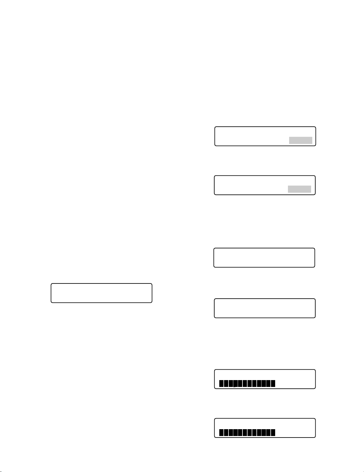
If the password entered is correct, the LCD display of
source system controller becomes as follows.
The LCD display of destination system controller(s)
become(s) as follows.
10. Press the CAM (SET) button of the source system controller.
The database copy will be started, and the LCD display
of source system controller becomes as follows.
The LCD display of destination system controller(s)
become(s) as follows.
Data Base Copy Mode
Admin Password _____
Data Base Rx Mode
Failed Sum=0000
Data Base Copy Mode
Admin Password ∗∗∗∗∗
Data Base Tx Mode
“Enter SET Button”
Data Base Rx Mode
Data Base Tx Mode
Completed 60%
Data Base Rx Mode
Completed 60%
Page 33
33
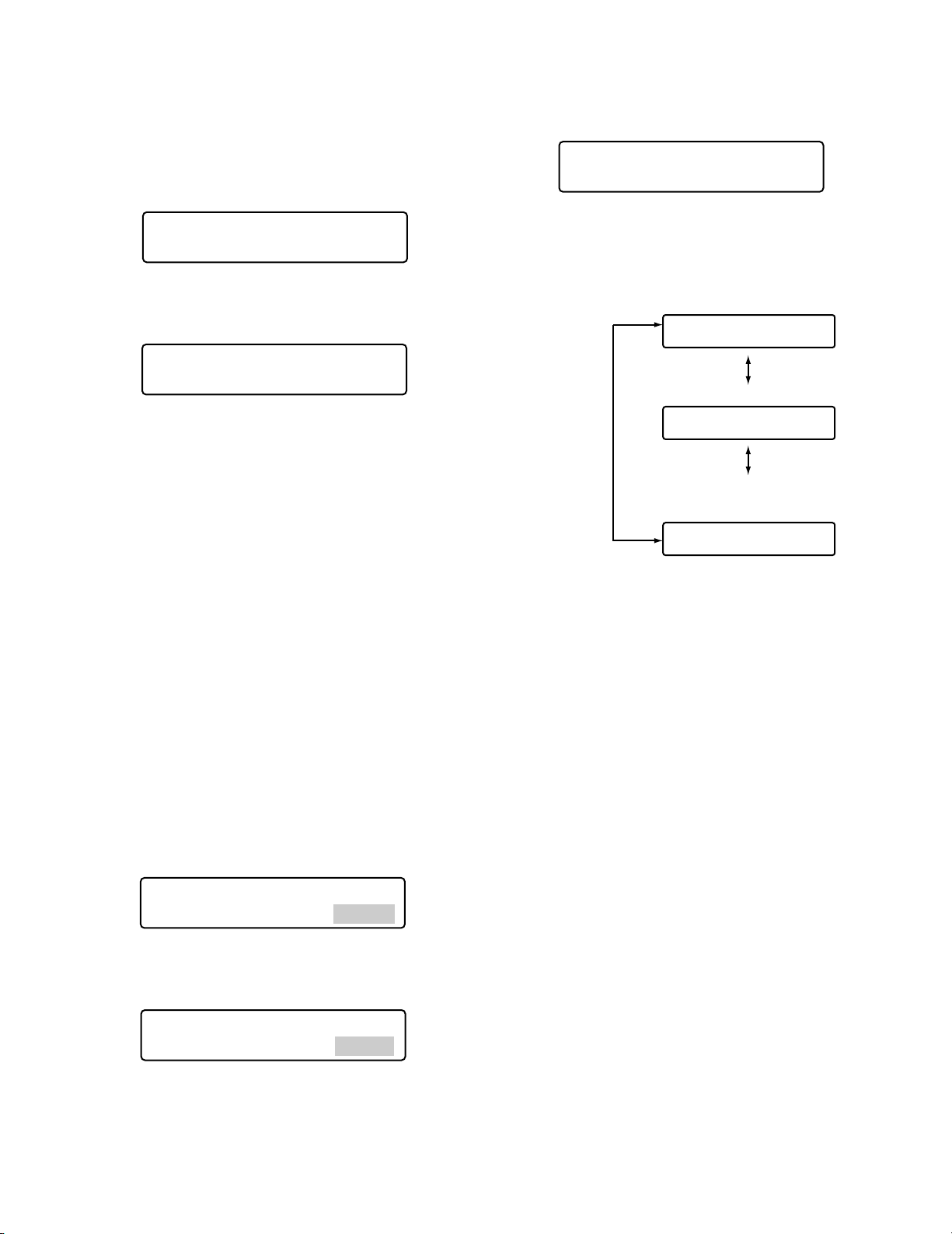
11. When the copy has been completed, the check sum
(SUM=nnnn) appears on the LCD of each system controller.
When the copy has been successfully completed, the
check sum is identical to each other.
The LCD display of source system controller becomes
as follows.
The LCD display of destination system controller(s)
becomes as follows.
Note: If the check sum is not identical, check the con-
nection of all the controllers, and retry the data base
copy.
12. Turn off the power of source and destination system
controllers.
■
PS·Data Operator Password Check
In case operators have forgotten their passwords, the
administrator can check the passwords in the following procedure.
● Operation
1. Turn off the power.
2. Turn on the power of system controller while holding
down the button 4 and MON (ESC) button.
“Admin Password” will appear on the LCD to enter the
password.
3. Enter the administrator password.
The password entered will be displayed as “∗” marks.
Notes:
• The factory default is “650”.
• If the password entered is wrong, the LCD display
will return to Step 2.
4. Press the CAM (SET) button.
If the password entered is correct, “User ID” and
“Password” of Operator 1 will appear on the LCD while
you are holding down the buttons.
5. To search a desired operator, rotate the JogDial.
The user ID and password of Operator 1 to 16 will
appear interchangeably.
6. Turn off the power.
No.01 User ID 650
Password 650
Data Base Rx Mode
Completed Sum=1733
Data Base Tx Mode
Completed Sum=1733
Operator 1 information
No.01 User ID 650
Password 650
Rotate the JogDial.
Operator 2 information
Rotate the JogDial.
No.02 User ID 1
Password 12345
Rotate the JogDial.
•
•
Operator 16 information
No.16 User ID 100
Password 100
PSD Password Check
Admin Password _____
PSD Password Check
Admin Password ∗∗∗∗∗
Page 34

34
Page 35

35
OPERATING PROCEDURES
(PS·DATA)
Page 36
36
BEFORE OPERATION
■ Power-on
Before operation, confirm the system composition.
Depending on system composition, some functions may be
unavailable.
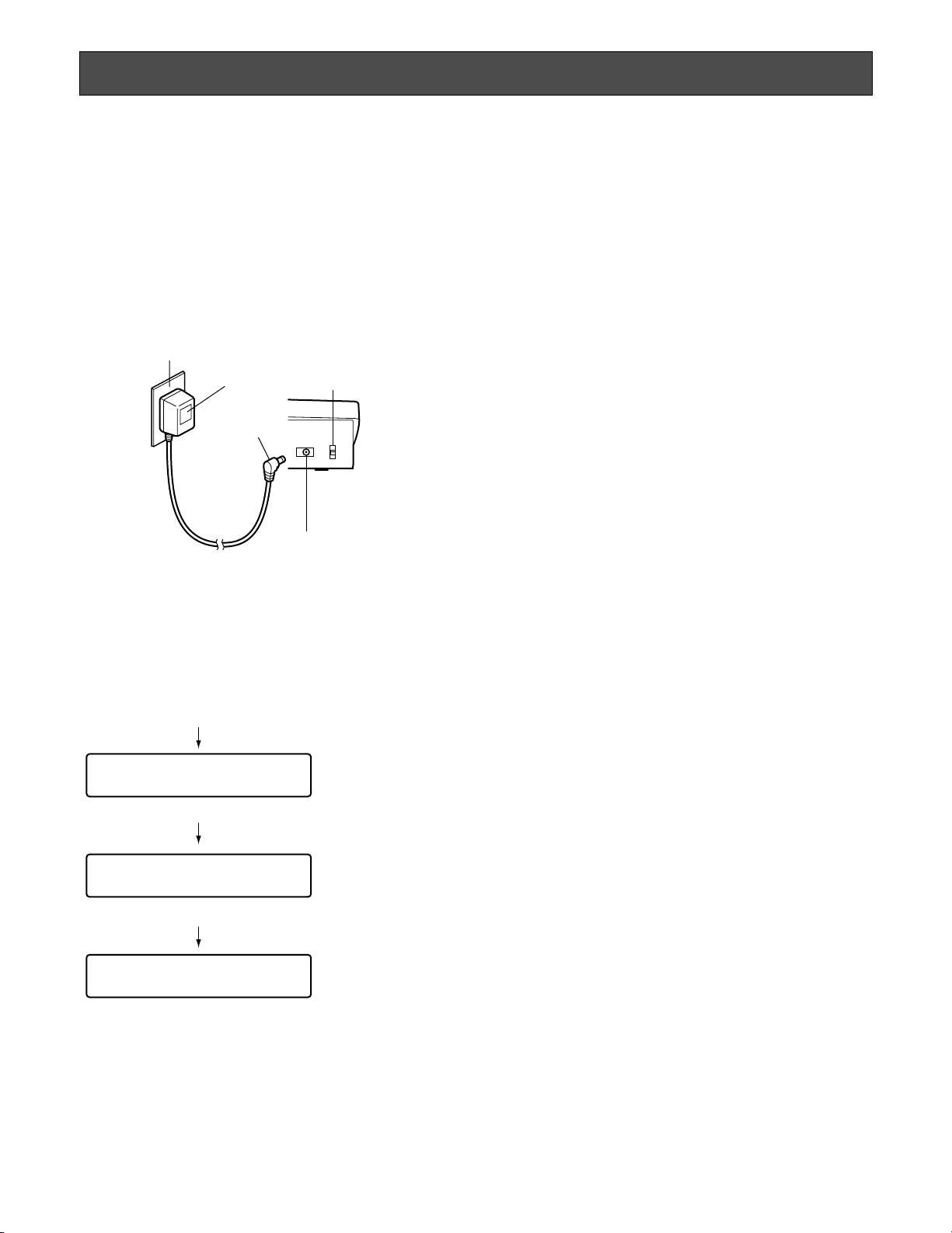
1. Plug the supplied AC adapter into an AC 120 V outlet.
2. Insert the DC 9 V plug into the DC 9 V Input Jack at the
rear panel.
The power will be turned on. Then, the OPERATE indicator will light up, and the software version → controller
number → login standby display will appear on the
LCD.
■ Power-off
After operation, power off the system controller as follows.
1. Log out from the system. (Refer to p. 40.)
2. Unplug the AC adapter from the AC outlet.
The power will be turned off. Then, the OPERATE indicator will go out.
When leaving away from the system controller
for a long time
Log out of the system and unplug the AC adapter from the
AC outlet. If the AC adapter is kept plugged into the AC
outlet, the adapter will consume electricity even after the
DC 9 V plug is removed from the DC 9 V Input Jack.
AC outlet
AC adapter
DC 9 V plug
DC 9 V Input Jack
Clamp
(Fastens the supplied
AC adapter's
power cord.)
DC9V IN
Power is turned on.
Ver.2.00
Software version appears.
PS·Data Mode
Controller No.1
Controller number appears.
PS·Data Mode
No User
Login standby display appears.
(Lighting for 2.0 seconds)
(Lighting for 1.0 second)
(Lighting until login)
Page 37
37
■ Basic Operation Flow
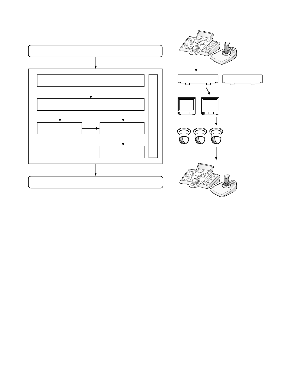
Login
System Unit Selection
Monitor Selection
System Unit
Setup and Operation
System Operation
Camera Selection
Camera setup
and control
Login
Unit selection
Monitor
selection
Operation
(Multiscreen segment
switching and sequence
Camera
selection
Operation
(Panning, Tilting,
and zooming, etc.)
Alarm suspension or reset
Logout
Logout at the
end of
operation
Page 38
38
● Button Buzzer Setting
You will perform the setting whether to activate a sound
when a button is pressed. Select the desired parameter by
rotating the JogDial.
Notes:
• Off or On is selectable. The factory default is On.
• If set to On, short buzzer will sound three times in the
following occasions.
(p. 17) Invalid, Prohibited
(p. 73) Level 1 Fixed
■ Operation Start (Login)
Before starting operation, user authentication by the ID and
password is required. (Refer to p. 72 Operator Registration
or Change for details on the setting of ID and password.)
Notes:
• User authentication is skipped when the auto login is
set to ON. (Refer to p. 71.)
• If no operation has been performed for 5 seconds or
more, the LCD display will return to the login standby
display.
• The factory default of operator information is as follows.
1. Turn on the power. (Refer to p. 36 Power-on and Poweroff.)
2. Wait until the login standby display appears.
3. Press the CAM (SET) button. “User ID” entry form will
appear on the LCD.
■ LCD/Buzzer Adjustment
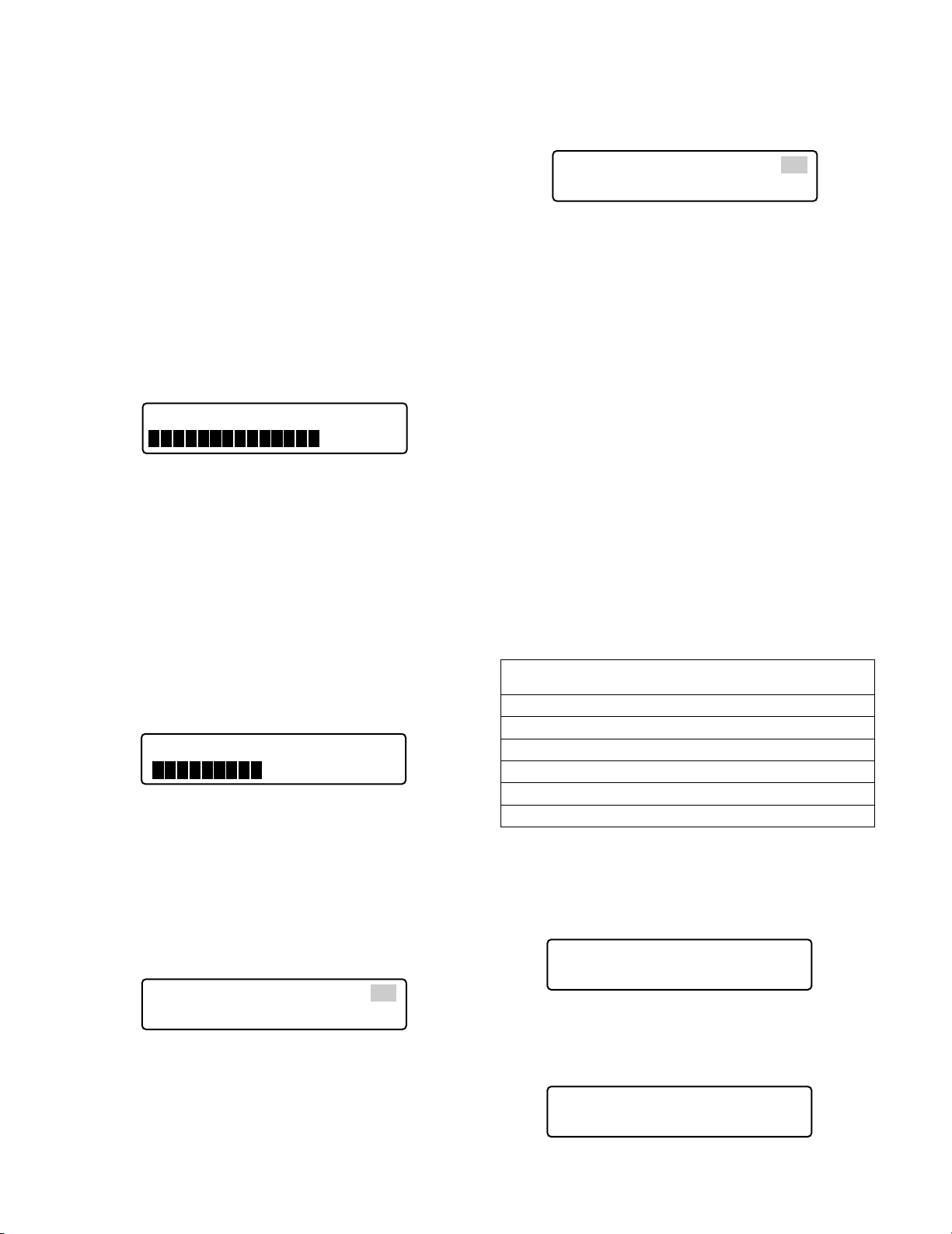
You can perform the settings of LCD brightness, LCD contrast, alarm buzzer, or button buzzer as follows.
1. Press the ADJUST button to select a desired menu.
Every pressing the button will display the brightness
setting menu → contrast setting menu → alarm buzzer
setting menu → button buzzer setting menu interchangeably.
Note: If no adjustment has been performed for 5 sec-
onds or more, these setting menus will automatically disappear and the LCD will return to the default
status.
2. After adjustment, press the MON (ESC) or EXIT button.
The LCD display will return to the default status.
● Brightness Level Adjustment
You can change the brightness level by rotating the
JogDial.
Adjust the LCD brightness level while watching the LCD.
Note: 1 (lowest) to 20 (highest) are available. The factory
default is 14.
● Contrast Level Adjustment
You can change the contrast level by rotating the JogDial.
Adjust the contrast level while watching the LCD.
Note: 1 (highest) to 20 (lowest) are available. The factory
default is 9.
● Alarm Buzzer Setting
You can change the duration time of alarm buzzer sound
by rotating the JogDial. Adjust the alarm buzzer setting
while watching the LCD.
Note: OFF, 1s (second), 2s, 3s, 4s, …, 30s, 40s, 50s, and
60s are available. The factory default is 2s.
Operator
No.
User ID Password Function
level
Camera
level
1 650 650 1 1
2 1 12345 1 1
3 100 100 2 1
4 101 101 3 1
5 102 102 3 1
6 103 103 3 1
Buzzer Operation On
LCD Bright 14
LCD Contrast 9
Buzzer Alarm 2s
PS·Data Mode
No User
User ID _____
Page 39
39
Notes:
• The smallest monitor, camera, and unit numbers are
displayed on the LCD.
• Three seconds after the unit number was determined, model number appears in place of unit number.
• When the ID or password is wrong, “Invalid” blinks
on the LCD. Then, the LCD returns to the login
standby display.
• When a system controller cannot communicate
properly with a system unit, the LCD display after
login becomes as follows.
In this case, check the connection and settings
between the system controller and system unit.
(Refer to p. 20.)
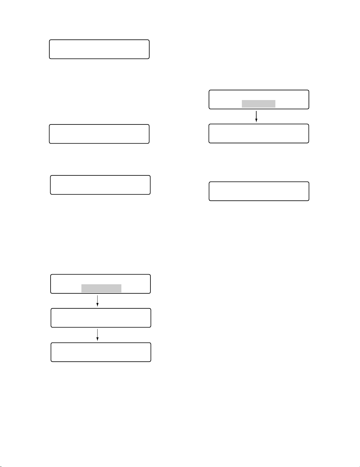
4. Enter the ID number by pressing the numeric buttons.
The user ID entered will appear on the LCD.
Notes:
• To delete a character, press the CLEAR button.
• You can also enter your user ID without pressing
the CAM (SET) button.
5. Press the CAM (SET) button. When the ID number is
correct, “Password” entry form appears on the LCD.
6. Enter the password by pressing the numeric buttons.
Then, press the CAM (SET) button.
Notes:
• To delete a character, press the CLEAR button.
• The password entered will be displayed as “∗”
marks.
7. When the password is correct, “Login OK” appears on
the LCD. Then, the LCD changes to the operation display.
User ID __650
User ID 650
Password _____
User ID 650
Password __∗∗∗
Invalid
•
PS Data Mode
No User
Mon-- Cam--- Unit01
Unit Error
Login OK
Mon04 Cam128 Unit16
F1 F2 F3 F4
Mon04 Cam128 HD316
F1 F2 F3 F4
Page 40
40
■ If You Have Forgotten the Login Password
Refer to the system administrator.
■ Operation Start (Auto Login)
When auto login is set to ON, operators can log into the
system without entering their passwords. The LCD display
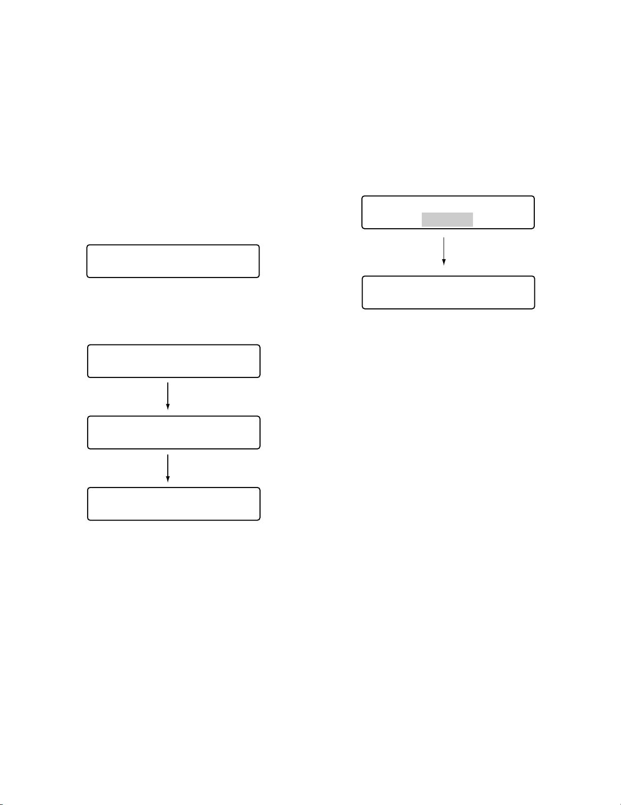
after power-on becomes as follows. (Refer to p. 71 Auto
Login/Logout Setup for details on the setting.)
1. When the power is turned on, “Auto Login” appears on
the LCD for a second.
2. The user ID of auto login user appear on the LCD.
Then, the operator will log into the system automatically.
Notes:
• This illustration is an example in which the operator
number is “650”.
• The smallest monitor, camera, and unit numbers are
displayed on the LCD.
• Three seconds after the unit number was determined, model number appears in place of unit number.
• Due to security, the password is not displayed on
the LCD.
■ Operation End (Logout)
You need to log out of the system:
• When finishing operation and turning off the power
• When changing an operator
1. During the login status, press the MON LOCK/LOGOUT
button while holding down the SHIFT button.
2. You will log out of the system, and "Logout" will appear
on the LCD. Then, the LCD returns to the login standby
display.
Alarm sign after logout
If power is being supplied even after logout, the current
system status will be continuously informed by “Alarm sign”
and the ALM SUSPEND indicator. If an alarm is newly activated after logout, “Alarm” sign will blink. (The blinking will
change to steady light when the alarm is automatically
reset.)
•
PS Data Mode
Auto Login
Logout
PS·Data Mode
No User
PS·Data Mode
User ID = 650
Mon01 Cam128 Unit16
F1 F2 F3 F4
Mon01 Cam128 HD316
F1 F2 F3 F4
Page 41
41
■ Recorder Selection
Notes:
• In advance, you need to set HDD-unit maps. (Refer to
p. 78 Associating Recorder Numbers with Unit
Numbers.)
• In the factory default, Recorder 1 to 16 is associated
with Unit 1 to 16.
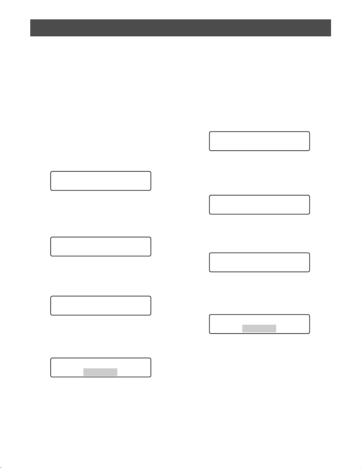
1. Enter a recorder number by pressing numeric buttons.
The entered number will appear on the LCD.
2. Press the RECORDER/UNIT button. The system will
become ready for control, and the monitor number,
camera number, and system unit number will appear on
the LCD.
Notes:
• Three seconds after, model number will appear in
place of unit number.
• If you have entered a wrong recorder number,
“Invalid” will appear on the LCD. Then, the LCD will
return to the status before the recording selection.
To control the system, you need to select a desired unit
(system unit, recorder, monitor, or camera) at the beginning.
■ System Unit Selection
Notes:
• In advance, you need to set the unit number for each
system unit. (Refer to the operating instructions of system units.)
• 1 to 99 are available for the unit number.
1. Enter a unit number by pressing the numeric buttons.
The entered number will appear on the LCD.
2. Press the RECORDER/UNIT button while holding down
the SHIFT button. The system will become ready for
control. Then, the monitor number, camera number,
and system unit number will appear on the LCD.
Note: Three seconds after, model number will appear
in place of unit number. To display the unit number
again, hold down the RECORDER/UNIT.
• If you have entered a wrong unit number, “Invalid”
will appear on the LCD. Then, the LCD will return to
the status before the system unit selection.
UNIT SELECTION
Mon01 Cam016 ___16
F1 F2 F3 F4
Mon02 Cam016 Unit16
F1 F2 F3 F4
Mon02 Cam016 HD316
F1 F2 F3 F4
Mon02 Cam128 ____2
F1 F2 F3 F4
Mon02 Cam016 Unit16
F1 F2 F3 F4
Mon02 Cam016 HD316
F1 F2 F3 F4
Invalid
Invalid
Page 42
42
Note: If camera numbers are associated with unit num-
bers, you can skip system unit selection. In the factory default, Camera 1 to 64 is associated with Unit
1 to 4. (Refer to p. 77 Associating Camera Numbers
with Unit Numbers.)
2. Select a camera number by pressing the numeric buttons. The entered number will appear on the LCD.
Notes:
• Refer to the operating instructions of system unit for
available camera numbers.
• You can also select cameras by pressing the + or –
button. When pressing the + button, the monitor will
display the image of camera with the higher channel number. When pressing the – button, the monitor will display the image of camera with the lower
channel number.
3. Press the CAM (SET) button. The system will become
ready for control. Then, the camera number will appear
on the LCD, and the image of selected camera will be
displayed on the active monitor.
Note: If you have entered a wrong camera number
(other than 1 to 999), “Invalid” will appear on the
LCD. Then, the LCD will return to the status before
selecting the camera.
Signs displayed on the LCD
“Seq”: This sign is displayed when a sequence is acti-
vated.
“Seq-P”: This sign is displayed when a sequence is
paused.
“C-Pnnn*”: This sign is displayed when a camera posi-
tion is selected. (Camera position is the combination of camera number and preset position number.) * nnn is a camera position number.
■ Monitor Selection
When two or more monitors are connected to a system unit,
you can select a desired monitor.
When monitor selection is unavailable, “Mon- -“ appears on
the LCD. The selected system unit does not support monitor selection.
1. Select a system unit (including a recorder) connected
to a monitor you wish to control. (Refer to p. 41 System
Unit Selection.)
2. Select the desired monitor number by pressing the
numeric buttons. The entered number will appear on
the LCD.
Note: Refer to the operating instructions of system unit
for available monitor numbers.
3. Press the MON (ESC) button. The monitor number will
appear on the LCD. The system will become ready for
monitor control.
Note: If you have entered a wrong monitor number,
“Invalid” will appear on the LCD. Then, the LCD will
return to the status before the monitor selection.
■ Camera Selection
When two or more cameras are connected to a system unit,
you can select a desired camera. You will also perform
camera selection when changing camera channels.
1. Select a system unit and monitor connected to a camera you wish to control. (Refer to p. 41 System Unit
Selection and Monitor Selection in this page.)
Mon01 Cam016 HD316
F1 F2 F3 F4
Mon01 Cam016 ___16
F1 F2 F3 F4
Mon01 Cam001 ___16
F1 F2 F3 F4
Mon02 Cam016 HD316
F1 F2 F3 F4
Mon02 Cam016 HD316
Invalid
Mon01 Cam016 HD316
F1 F2 F3 F4
Mon01 Cam016 HD316
Invalid
Mon01 Cam001 HD316
F1 F2 F3 F4
Page 43

43
Note: Available zooming rates differ depending on sys-
tem units. (Refer to the operating instructions of system units for details.)
■
Tour Sequence/Group Sequence
Sequence monitoring is the function to switch camera
images automatically, according to the order registered in
the system unit. The following procedure is available when
a selected system unit has the tour or group sequence
monitoring function.
Note: Before performing the procedure, the sequence
setup of system unit is required.
1. Select a system unit and monitor. (Refer to p. 41
System Unit Selection and p. 42 Monitor Selection.)
2. Enter a desired sequence number.
3. To activate a tour sequence, press the TOUR
SEQ/GROUP SEQ button.
To activate a group sequence, press the TOUR
SEQ/GROUP SEQ button while holding down the SHIFT
button. The sequence will be activated, and “Seq” will
appear on the monitor, in place of the camera number.
Notes:
• If you have skipped entering the sequence number
in Step 2, Tour or Group Sequence 1 will be activated.
• If the selected recorder supports sequence pausing, you can pause the sequence by pressing the
SEQ PAUSE/SEQ STOP button. During the
sequence pause, “Seq-P” will appear on the LCD in
place of “Seq”.
4. To quit the sequence monitoring, press the SEQ
PAUSE/SEQ STOP while holding down the SHIFT button. The monitor display will return to the spot mode.
Note: If the selected system unit does not support
sequence stop, stop the sequence by selecting a
camera or activating the multiscreen display. (Refer
to p. 42 Camera Selection or Multiscreen Display in
this page.)
The following are the procedures to control system units
(including recorders).
■ Multiscreen Display
The following procedure is available when a selected system unit (for example, a hard disk recorder) has the multiscreen display function.
1. Select a system unit and monitor. (Refer to p. 41
System Unit Selection and p. 42 Monitor Selection.)
2. Do either of the following.
• Press the MULTI SCREEN button.
• Press the desired numeric buttons (refer to the dia-
gram), then press the MULTI SCREEN button.
Images will be displayed in the specified multiscreen
segment pattern on the monitor. Every pressing the
MULTI SCREEN button can change the multiscreen
segment pattern.
Numeric buttons Multiscreen display pattern
0 4 segments
1 7 segments
2 9 segments
3 10 segments
4 13 segments
5 16 segments
Note: Available multiscreen segment patterns differ
depending on system units. Refer to the operating
instructions of system units.
■ Electronic Zooming
The following procedure is available when a selected system unit has the electronic zooming function.
1. Select a system unit, monitor, and camera. (Refer to p.
41 System Unit Selection, p. 42 Monitor Selection, and
p. 42 Camera Selection)
2. Press the EL-ZOOM button. The camera image on the
monitor will be zoomed. Every pressing the EL-ZOOM
button can change the zooming rate.
3. To move the zoomed area, move the 3D joystick to
desired directions. (Refer to the operating instructions
of system unit.)
SYSTEM UNIT CONTROL
Mon02 Seq HD316
F1 F2 F3 F4
Page 44

44
■ On-screen Display (OSD) Control
You can toggle the OSD information (display parameters
such as camera title, monitor number, and recorder number) on the active monitor screen.
1. Select a desired monitor. (Refer to p. 42 Monitor
Selection.)
2. To toggle the OSD information, press the OSD button.
Note: OSD information differs depending on system
units. Refer to the operating instructions of system
units.
■ System Function Control
You can recall system functions (functions of system units)
by pressing the corresponding function numbers. Refer to
the operating instructions of system units for the association
of function numbers and system functions.
1. Select a system unit and monitor. (Refer to p. 41
System Unit Selection and p. 42 Monitor Selection.)
2. Enter a function number by pressing the numeric buttons.
3. Press the CAM FUNC/SYS FUNC button while holding
down the SHIFT button.
The associated system function will be activated.
Note: If you assign system functions to the joystick function
buttons (A, B, and top buttons), you can recall system
functions by pressing these buttons. Refer to p. 57
MENU FUNCTION DESCRIPTIONS for details.
Mon01 Cam001 ____3
F1 F2 F3 F4
Page 45
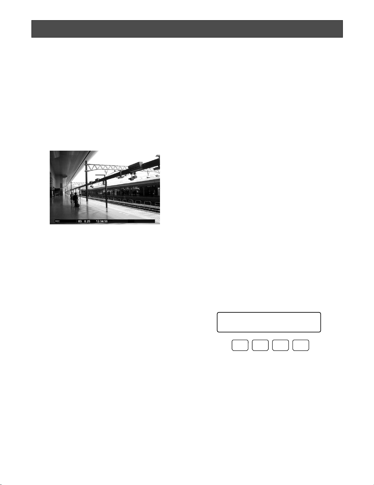
45
From this system controller, you can control the following
functions of digital disk recorders supporting PS·Data. You
will control a recorder in the status in which a recorder has
been selected.
Note: Some parts of monitor displays, described on this
document, may differ from the actual status.
■ Manual Recording
1. To start the recording, press the REC button.
Recording will be started.
2. To stop the recording, press the REC button again for
two seconds.
Note:
Refer to the operating instructions of recorder for the
available recording modes and total recording time.
■ Playback
1. Select a desired recorder.
Refer to p. 41 Recorder Selection.
2. Select a camera whose picture you wish to play back.
Refer to p. 42 Camera Selection.
When camera selection is not necessary, skip to Step 3.
3. To start playback, press the PLAY/PAUSE button.
The playback will be started.
Note: The playback start point differs depending on
recorders. (Refer to the operating instructions of
recorder.)
Operations available during playback
Pause: Refer to p. 11 @5 Play/Pause button.
Single frame skip (Forward or backward field
advance): Refer to p. 11 @7 JogDial.
Fast forward or fast reverse (Fast-forward or
rewind): Refer to p. 11 @7 Shuttle ring.
Hold playback speed: Refer to p. 12 @8 Shuttle hold
button.
Skip (WJ-HD300 and WJ-HD500 Series): Refer to p.
11 @7 JogDial.
Play the latest recorded image (WJ-HD300 Series
only): Refer to p. 11 !5 Go to last button.
Multiscreen display: Refer to p. 11 !7 Multiscreen
selection button.
Marking (WJ-HD300 Series only): Refer to p. 11 !85
Mark button.
4. To stop playback, press the STOP button.
The playback will be stopped.
■ Search Playback
Recorders have search playback functions based on
recording times or recording events. When searching playback images, you can activate these functions from this
system controller.
Notes:
• WJ-HD100 Series does not support search playback.
• WJ-HD300 Ver. 1.2 or later / WJ-HD200 Ver. 1.24 or
later / WJ-HD220 supports search playback.
● How to Display Search Lists
1. Press the SEARCH/T&D SEARCH button. “Search
Mode” menu will appear on the LCD, and a search list
(date-and-time entry form, record list, or recording
event list, etc.) will be displayed on an active monitor.
Notes:
• Every pressing the SEARCH/T&D SEARCH button
can change search list display. (For example,
Record list → Thumbnail Display → Record List …)
• The search list firstly displayed differs depending
on recorders.
2. Perform operations while watching the active monitor.
Note: The operation details differ depending on
recorders. Refer to pp. 46 to 48.
RECORDER CONTROL
Search Mode HD300
Thumb Text Copy
F1 F2 F3 F4
Example: WJ-HD300 Series
Page 46
46
Note: While holding down the SHIFT button, the LCD dis-
play will become as follows.
Available buttons and functions
F1 button: Thumb or List
Changes the monitor display between the recording event
list window and thumbnail menu.
F3 button: Text
Displays text information of selected event on the recording
event list.
F4 button: Copy
Displays the DATA COPY window while the recording
event, VMD search, or marking list window is displayed.
F1 button while holding down the SHFT button: Nr-A
Specifies the normal or event recording area for the playback media.
F2 button while holding down the SHIFT button: Cp-A
Specifies the copy area for the playback media.
F3 button while holding down the SHIFT button: Cpy1
Specifies the external recording device connected to COPY
1 for the playback media. (This button is available for WJHD316A and WJ-HD309.)
F4 button while holding down the SHIFT button: Cpy2
Specifies the external recording device connected to COPY
2 for the playback media. (This button is available for WJHD316A and WJ-HD309.)
Notes:
• The monitor display is not changed even if pressing the
F1 button while the date-and-time entry form is displayed.
• To close the monitor display activated by the function
buttons, press the MON (ESC) button.
• The DATA COPY window is not displayed while a
thumbnail window is displayed.
• Refer to the operating instructions of recorder for details
on each function.
Controls commonly available
<Main unit>
Shuttle ring clockwise: Moves to the next page.
Shuttle ring counterclockwise: Moves to the previous
page.
JogDial clockwise or counterclockwise: Changes the
selected parameter.
Numeric buttons: Enters numeric parameters.
CAM (SET) button:
Determines the selected parameter
or searching filter setting.
MON (ESC) or EXIT button: Closes the search list dis-
play.
<3D joystick unit>
3D joystick upward (▲): Moves the cursor.
3D joystick downward (▼): Moves the cursor.
3D joystick to the left (t): Moves the cursor to the left.
3D joystick to the right (s): Moves the cursor to the
right.
Zoom wheel controller to the right or left: Changes
the search list display. (For example, Record list ↔
Thumbnail Display ↔ Record List …)
Top button: Determines the selected parameter or
searching filter setting.
● Operation (WJ-HD300 Series)
If you press the SEARCH/T&D SEARCH button, the dateand-time entry form will appear on the monitor. The search
list display will change as follows.
Date-and-time entry form → Recording event list → VMD
search list → Marking list → Date-and-time entry form →…
Note: To quit search playback, press the MON (ESC) or
EXIT button. Live image will be displayed again on the
monitor.
The following are the details on LCD display patterns and
function buttons.
LCD display while the event list is displayed
on the monitor
LCD display while the thumbnail menu is
displayed on the monitor
Search Mode HD300
Nr-A Cp-A Cpy1 Cpy2
F1 F2 F3 F4
Search Mode HD300
Thumb Text Copy
F1 F2 F3 F4
Search Mode HD300
List Text Copy
F1 F2 F3 F4
Page 47
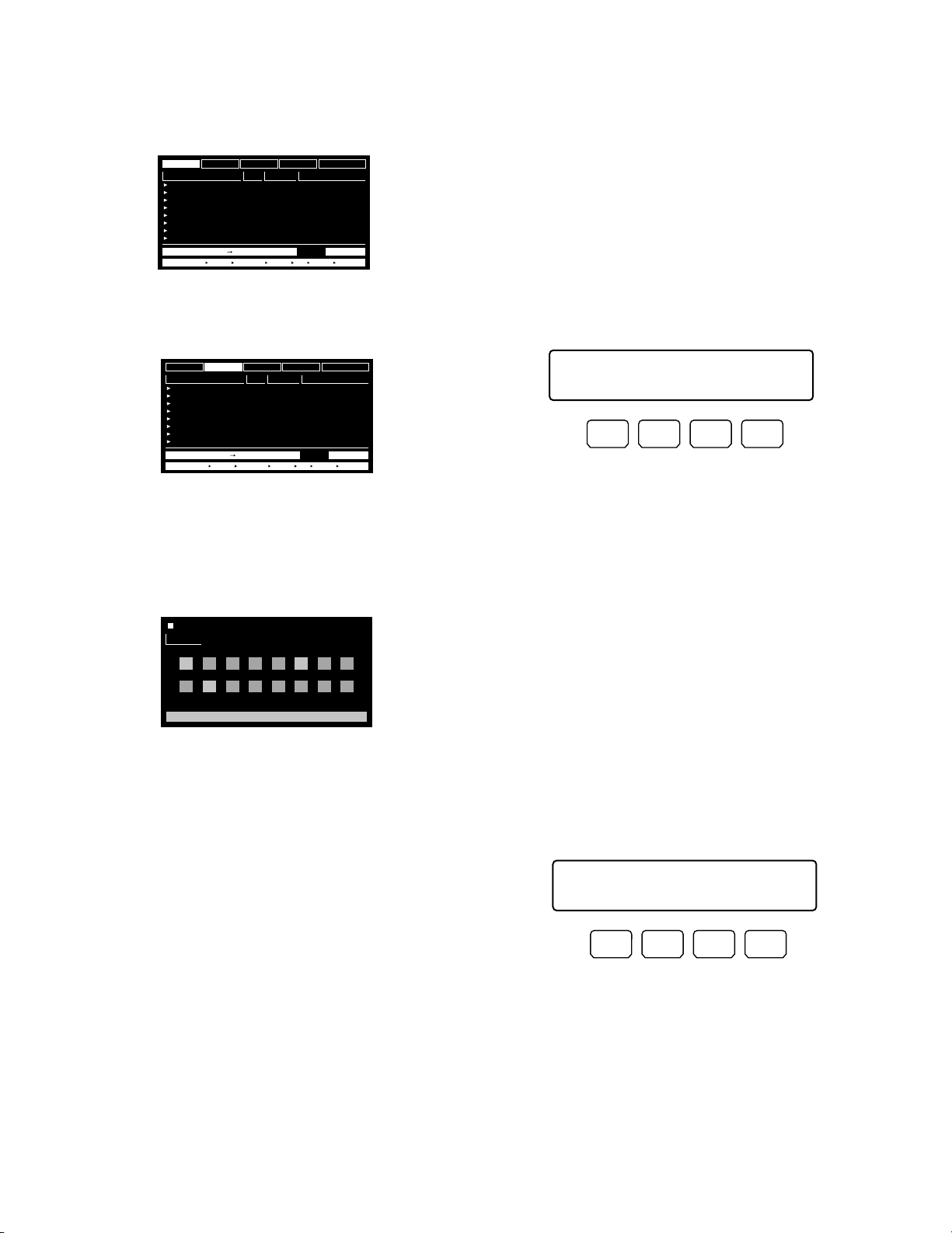
47
Example of searching filter display and
settings
1. Repeat pressing the SEARCH/T&D SEARCH button to
display the recording event list window.
2. To select “CAMERA” for the searching filter, move the
3D joystick to right or left.
3. To determine the filter setting, press the CAM (SET) button of main unit or top button of 3D joystick unit.
The searching filter window will appear on the active
monitor, and the selected camera channels will be displayed on the window.
Note: When you press the MON (ESC) button, the
searching filter window will be closed.
4. To select a desired camera channel, move the 3D joystick to right of left.
5. To change the filter setting, do either of the following.
• Rotate the JogDial clockwise or counterclockwise.
• Press the + or – button.
The selected camera channels will turn to blue, and
other channels will be displayed in gray.
Note: To change the filter settings of two or more cam-
era channels, repeat Step 5.
6. Press the CAM (SET) button of main unit or top button
of 3D joystick unit.
The associated recording event will be displayed on the
monitor.
● Operation (WJ-HD500 Series)
If you press the SEARCH/T&D SEARCH button, the dateand-time entry form will appear on the monitor. The search
list display will change as follows.
Record List → Thumbnail Display → Record List →…
Note: To quit search playback, press the MON (ESC) or
EXIT button. Live image will be displayed again on the
monitor.
The following are the details on LCD display patterns and
function buttons.
LCD display
Available buttons and functions
F1 button: Edit
You will press this button when editing the Search
Editing Area on the Record List.
F2 button: Group
The selected group is switched by rotation.
F3 button: Alm
Only the Alarm and Emergency Record List will be displayed on the monitor.
F4 button: Copy
The selected recording images will be copied to a
external recording device (DVD or CD-R).
F1 button while holding down the SHIFT button: Drive
Record List of external recording device will be displayed. The LCD display becomes as follows.
Note: Refer to the operating instructions of recorder for
details on each function.
TIME&DATE
CAMERA
REC EVENT
TEXT
TIME&DATE
APR.25.03*12:34:56 AM
APR.25.03*12:34:56 AM
APR.25.03*12:34:56 AM
APR.25.03*12:34:56 AM
APR.25.03*12:34:56 AM
APR.25.03*12:34:56 AM
APR.25.03*12:34:56 AM
APR.25.03*12:34:56 AM
TIME&DATE SEARCH REC EVENT SEARCH VMD SEARCH MARK
CAM REC EVT
01ch
MANUAL
01ch
MANUAL
01ch
MANUAL
01ch
MANUAL
01ch
MANUAL
01ch
MANUAL
01ch
MANUAL
01ch
MANUAL
UNLOCK FILTER
TEXT
ABCDEFGHIJKLMNOP
ABCDEFGHIJKLMNOP
ABCDEFGHIJKLMNOP
ABCDEFGHIJKLMNOP
ABCDEFGHIJKLMNOP
ABCDEFGHIJKLMNOP
ABCDEFGHIJKLMNOP
ABCDEFGHIJKLMNOP
TOTALAPR.25.03*12:34:56 AM APR.25.03*12:34:56 AM 100
TIME&DATE
CAMERA
REC EVENT
TEXT
TIME&DATE
APR.25.03*12:34:56 AM
APR.25.03*12:34:56 AM
APR.25.03*12:34:56 AM
APR.25.03*12:34:56 AM
APR.25.03*12:34:56 AM
APR.25.03*12:34:56 AM
APR.25.03*12:34:56 AM
APR.25.03*12:34:56 AM
TIME&DATE SEARCH REC EVENT SEARCH VMD SEARCH MARK
CAM REC EVT
01ch
MANUAL
01ch
MANUAL
01ch
MANUAL
01ch
MANUAL
01ch
MANUAL
01ch
MANUAL
01ch
MANUAL
01ch
MANUAL
UNLOCK FILTER
TEXT
ABCDEFGHIJKLMNOP
ABCDEFGHIJKLMNOP
ABCDEFGHIJKLMNOP
ABCDEFGHIJKLMNOP
ABCDEFGHIJKLMNOP
ABCDEFGHIJKLMNOP
ABCDEFGHIJKLMNOP
ABCDEFGHIJKLMNOP
TOTALAPR.25.03*12:34:56 AM APR.25.03*12:34:56 AM 100
CAMERA FILTERING
CAMERA
1
2345
9 10 11 12 13 14 15 16
SET : [ SET ] CANCEL : [ ESC ]
6 78
Search Mode HD500
Edit Group Alm Copy
F1 F2 F3 F4
Search Mode HD500
Drive
F1 F2 F3 F4
Page 48
48
Example of F1 button use
1. Press the SEARCH/T&D SEARCH button. Record List
will be displayed on the active monitor.
2. Press the F1 button.
Search Editing Area will appear on the Record List.
3. Move the cursor to a position to be edited by perform-
ing either of the following.
• Move the 3D joystick controller to the right or left.
• Rotate the shuttle ring clockwise or counterclock-
wise.
4. Enter the desired date and time by performing either of
the following.
• Rotate the JogDial clockwise or counterclockwise.
• Press the + or – button.
5. Repeat Step 3 and 4 to edit Search Editing Area.
6. After editing, press the CAM (SET) button.
The associated record will be displayed on the Record
List.
● Operation (WJ-HD200 Series)
The following is the LCD display and operating procedure
of search playback.
LCD display
Operating procedure
1.
Press the SEARCH/T&D SEARCH button. The time & date
search window will be displayed on the active monitor.
2. Move the cursor to a position to be edited by performing either of the following.
• Move the 3D joystick controller to the right or left.
• Rotate the shuttle ring clockwise or counterclock-
wise.
3. Enter the desired date and time by performing either of
the following.
• Rotate the JogDial clockwise or counterclockwise.
• Press the + or – button.
4. Press the PLAY/PAUSE button or CAM (SET) button.
The specified playback image will be displayed on the
monitor.
Notes:
• To quit search playback, press the MON (ESC) or EXIT
button. Live image will be displayed again on the monitor.
• You will use no function buttons for controlling the
recorder.
• Image to be played back differs depending on
recorders. (Refer to the operating instructions of
recorder.)
DATE MAY29.00
GROUP NO TIME
010009 G2G123:59:59 T/L
010008
G3
010007
ALL
010006
ALL
010005
010004
G4
010003
ALL
G3
010002
COPY DONE! LEFT:20%
PLAY:B ESC:FSTOP SEL:JOG
SEARCH:DISPLAY
ALL GROUP
REC-MODE
22:15:40 M/S ALM-TRM12
21:00:07
17:33:05
7:23:11
6:59:44
8:55:28
0:01:28
O/S ALM-VMD3
T/L
T/L EMR
M/S ALM-PC4
T/L MAN
T/L ALM-TRM1
2343RECORD)(TOTAL
DATE MAY29.00
GROUP NO TIME REC-MODE
010009
G2G123:59:59 T/L
010008
G3
010007
ALL
010006
ALL
010005
010004
G4
010003
ALL
G3
010002
MAY29.00SEARCH: 0:01 G1
SEL:←→ CHG:+– EXE:SET ESC:FSTOP
Search Editing Area
ALL GROUP
22:15:40 M/S ALM-TRM12
21:00:07
17:33:05
7:23:11
6:59:44
8:55:28
0:01:28
O/S ALM-VMD3
T/L
T/L EMR
M/S ALM-PC4
T/L MAN
T/L ALM-TRM1
2343RECORD)(TOTAL
Search Mode HD200
03-05-07 20:30:00
TO SEARCH PUSH PLAY KEY
DATE MAY29.00
GROUP NO TIME REC-MODE
010009
G2G123:59:59 T/L
010008
010007
G3
ALL
010006
ALL
010005
010004
G4
010003
ALL
G3
010002
MAY29.00SEARCH: 9:31 G1
SEL:←→ CHG:+– EXE:SET ESC:FSTOP
ALL GROUP
22:15:40 M/S ALM-TRM12
21:00:07
17:33:05
7:23:11
6:59:44
8:55:28
0:01:28
O/S ALM-VMD3
T/L
T/L EMR
M/S ALM-PC4
T/L MAN
T/L ALM-TRM1
2343RECORD)(TOTAL
Page 49
49
■ Time & Date Search Playback
You can search playback images by entering a desired
recording date and time.
Note: To cancel the entry, press the MON (ESC) or EXIT
button. The LCD display will return to the normal status.
1. Press the T & D SEARCH button while holding down the
SHIFT button. The time-and-date entry form will appear
on the LCD.
Note: You can change the display pattern setting.
(Refer to p. 71 Time & Date Search Display Pattern.)
2. Move the cursor to a position to be edited by performing either of the following.
• Move the 3D joystick controller to the right or left.
• Rotate the shuttle ring clockwise or counterclock-
wise.
3. Enter the desired date and time by by performing either
of the following.
• Rotate the JogDial clockwise or counterclockwise.
• Press the numeric buttons.
4. Press the PLAY/PAUSE or CAM (SET) button. The
image on the specified date and time will be played
back on the active monitor.
After the image has been played back, the LCD will
return to the default status.
When using WJ-HD500 Series
Group selection is required after Step 3. Perform as follows.
1. Press the PLAY/PAUSE or CAM (SET) button.
"Group Select" menu will appear on the LCD.
2. Select a desired group to play back by rotating the
JogDial.
3. Press the PLAY/PAUSE or CAM (SET) button again.
The image on the specified date and time will be
played back on the active monitor.
Note: Image to be played back differ depending on
recorders. (Refer to the operating instructions of
recorder.)
■ Other Available Functions
Depending on recorders, the following functions are available.
• Disk selection (WJ-HD300 Series only) (p. 67)
• A - B repeat playback setting (WJ-HD300 Series only)
(p. 67)
• Filtering ON/OFF (WJ-HD300 Series only) (p. 68)
• Displaying camera and playback image (WJ-HD500
Series only) (p. 68)
• Recorded-image copy (WJ-HD500 Series only) (p. 83)
• Alarm search (WJ-HD200 Series / WJ-HD100 Series) (p.
84)
Mmm/DD/YYYY HH:MM 12
Mar/17/2004 12:00 AM
Mmm/DD/YYYY HH:MM 12
Mar/16/2004 01:32 PM
HD500 Index Search
Group Select=All-G
Page 50

50
You can control cameras from this system controller.
■ Camera Panning/Tilting Control
The following procedure is available when panning/tilting
heads or combination cameras are connected to system
units.
1. Select a system unit, monitor, and desired camera.
(Refer to p. 41 System Unit Selection, p. 42 Monitor
Selection, and p. 42 Camera Selection.)
2. Move the 3D joystick to desired directions.
The selected camera will pan and tilt. If you move the
3D joystick widely, you can pan and tilt the camera
faster.
Note: Panning/tilting speed differs depending on cameras.
■ Zooming Control
The following procedure is available when a motorized
zoom lens is attached to a camera.
1. Select a system unit, monitor, and desired camera.
(Refer to p. 41 System Unit Selection, p. 42 Monitor
Selection, and p. 42 Camera Selection.)
2. Move the zoom wheel controller (located at the top of
3D joystick).
• Turning the zoom wheel controller to the right will
zoom the image. (The zooming level will go up.)
• Turning the controller to the left will widen the
scene. (The zooming level will go down.)
Note: Available zooming rates differ depending on the
motorized zoom lens.
■ Lens Iris Control
The following procedure is available when a selected camera has an adjustable lens iris.
1. Select a system unit, monitor, and desired camera.
(Refer to p. 41 System Unit Selection, p. 42 Monitor
Selection, and p. 42 Camera Selection.)
2. Adjust the lens iris by pressing the IRIS OPEN or
CLOSE button of 3D joystick unit.
• Pressing the IRIS OPEN will open the lens iris.
• Pressing the IRIS CLOSE will close the lens iris.
To reset the lens iris to the default status
Press the A button of 3D joystick unit.
The lens iris will be adjusted automatically.
Note: As the factory default, iris reset has been assigned to
the A button. You can assign iris reset to the function
buttons (F1 to F4/F5 to F8) or joystick function buttons
(A, B, and top buttons).
(Refer to p. 63 for assignment.)
■ Lens Focus Control
The following procedure is available when a selected camera has a lens whose focus is adjustable.
1. Select a system unit, monitor, and desired camera.
(Refer to p. 41 System Unit Selection, p. 42 Monitor
Selection, and p. 42 Camera Selection.)
2. Adjust the lens focus by pressing the FOCUS NEAR
and FAR buttons of 3D joystick unit.
• Pressing the FOCUS NEAR will bring the focus
nearer to the object.
• Pressing the FOCUS FAR will bring the focus farther
from the object.
To adjust the lens focus automatically
Press the B button of main unit or top button of 3D joystick
unit. The lens focus will be adjusted automatically for the
object displayed when you pressed the button.
Note: As the factory default, auto focus has been assigned
to the B button and top button. You can assign auto
focus to the function buttons (F1 to F4/F5 to F8) or joystick function buttons (A, B, and top buttons). (Refer to
p. 63 for assignment.)
CAMERA CONTROL
WIDE
TELE
Zoom wheel controller
Page 51
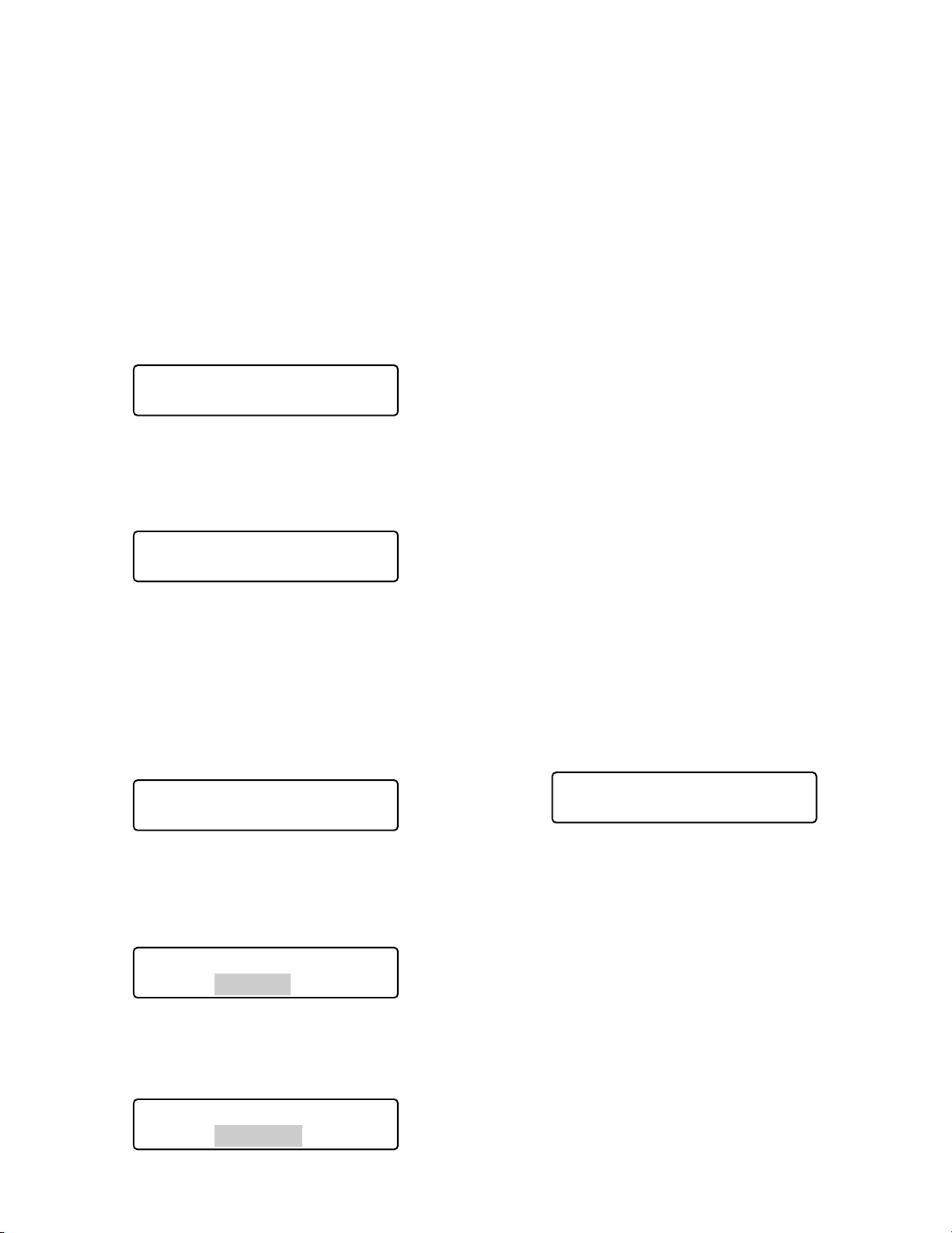
51
■ Preset Position Control
Preset position is the function to register camera monitoring
positions (preset positions) associated with position numbers. By entering the position numbers, you can move cameras to the preset positions.
Note: To activate this function, you need to register the pre-
set positions of combination camera.
1. Select a system unit, monitor, and desired camera.
(Refer to p. 41 System Unit Selection, p. 42 Monitor
Selection, and p. 42 Camera Selection.)
2. Enter a preset position number by pressing the numeric
buttons. The entered number will appear on the LCD.
3. Press the PRESET/PGM PRESET button.
The camera will move to the registered preset position,
and the preset position image will be displayed on an
active monitor.
To register preset positions
1. Move the camera to a desired position by moving the
3D joystick.
2. Enter a preset position number you wish to register by
pressing the numeric buttons.
The entered number will appear on the LCD.
3. Press the PRESET/PGM PRESET button while holding
down the SHIFT button.
The preset position will be registered, and “Memory”
will appear on the LCD.
Note: If the registration have failed, “Invalid” will appear
on the LCD. (Example: When the selected camera
does not support preset position control)
■ Home Position Control
Home position is the default preset position. You can move
the camera to the home position only by pressing the PRESET/PGM PRESET button.
Note: To activate this function, you need to register the
home position of combination camera. (Refer to the
operating instructions of combination camera.)
1. Select a system unit, monitor, and desired camera.
(Refer to p. 41 System Unit Selection, p. 42 Monitor
Selection, and p. 42 Camera Selection.)
2. Press the PRESET/PGM PRESET button. The camera
will move to the registered home position, and the home
position image will be displayed on an active monitor.
Note: You can also move the camera to the home posi-
tion by pressing the button 0, and then the PRESET/PGM PRESET button.
■ Camera Function Control
You can recall the camera functions of combination cameras by entering the function number from this system controller. Refer to the operating instructions of combination
camera for the association of camera numbers and functions.
1. Select a desired combination camera. (Refer to p. 42
Camera Selection.)
2. Enter a camera function number by pressing the
numeric buttons. The entered number will appear on
the LCD.
3. Press the CAM FUNC/SYS FUNC button.
The associated camera function will be activated.
Note: If you assign camera functions to the joystick function
buttons (A, B, and top buttons), you can recall the camera functions by pressing these buttons. Refer to p. 57
MENU FUNCTION DESCRIPTIONS for details.
Mon02 Cam001 ____3
F1 F2 F3 F4
Mon02 Cam001 Pre003
F1 F2 F3 F4
Mon01 Cam001 ___12
F1 F2 F3 F4
Mon01 Cam001 Pre012
Memory
Mon01 Cam001 Pre012
Invalid
Mon01 Cam001 ____3
F1 F2 F3 F4
Page 52
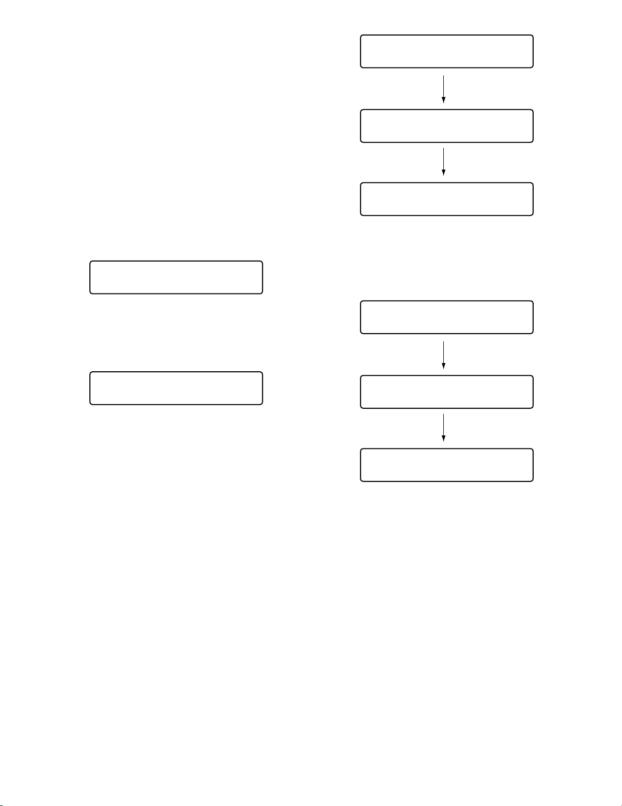
52
■ Camera Position Control
Camera position is the association of camera numbers and
preset position numbers. Up to 1 000 camera positions are
registrable in the system, and you can move a desired
camera to a desired preset position only by entering a camera position number.
Note: To activate this function, preset positions and camera
positions need to be registered. (Refer to p. 51 To register preset positions and p. 76 Camera Position
Registration or Clearing.)
1. Select a system unit and monitor. (Refer to p. 41
System Unit Selection and p. 42 Monitor Selection.)
2. Enter a camera position number by pressing the numeric buttons. The entered number will appear on the LCD.
3. Press the CAM POSI button.
The registered camera and preset position will be
selected, and the camera position image will be displayed on the active monitor.
■ Camera Selection Recall
Every time you select a camera or camera position, this
system controller memorizes up to 10 steps of camera
selection. You can recall these operations in order or
reverse order. In the following procedure, you can track
back the camera images formerly displayed.
Note: After power-off or system unit selection, the
memorized camera operations will be cleared.
In the following example, Camera 1 → 3 → 128 has
been selected.
1. Press the – button while holding down the HISTORY
button. The camera image formerly selected will be displayed on an active monitor. (Camera 128 → 3)
Note: To recall camera images more formerly selected
one by one, repeat pressing the – button while holding down the HISTORY button. (You can recall up to
10 camera images.)
2. To return to the camera image more recently selected,
press the + button while holding down the HISTORY
button. The camera image more recently selected will
be displayed on the monitor. (Camera 1 → 3 → 128)
Note: To return to the camera images more recently
selected one by one, repeat pressing the + button
while holding down the HISTORY button.
■ Wiper Control
The following procedure is available when a selected camera (housing) is equipped with a wiper.
1. Select a system unit, monitor, and desired camera.
(Refer to p. 41 System Unit Selection, p. 42 Monitor
Selection, and p. 42 Camera Selection.)
2. Keep pressing the WIPER button.
The wiper will be activated while this button is being
pressed.
Mon02 Cam128 HD316
F1 F2 F3 F4
Mon02 Cam003 HD316
F1 F2 F3 F4
Mon01 Cam001 ___11
F1 F2 F3 F4
Mon01 C-P011 HD316
F1 F2 F3 F4
Mon02 Cam001 HD316
F1 F2 F3 F4
Mon02 Cam001 HD316
F1 F2 F3 F4
Mon02 Cam003 HD316
F1 F2 F3 F4
Mon02 Cam128 HD316
F1 F2 F3 F4
Page 53

53
■ Defroster Control
The following procedure is available when a selected camera (housing) is equipped with a defroster.
1. Select a system unit, monitor, and desired camera.
(Refer to p. 41 System Unit Selection, p. 42 Monitor
Selection, and p. 42 Camera Selection.)
2. Press the DEF ON/OFF button.
The defroster will be activated.
Note: The defroster will be automatically deactivated
after the specified time.
3. To deactivate the defroster, press the DEF ON/OFF button while holding down the SHIFT button.
■ Auxiliary Control
You can control one or two auxiliary control devices. The
following procedure is available when an auxiliary control
device, such as Receiver WV-RC150, is connected to a
system unit.
Note: The operation procedure differs depending on the
mode setting (=latch or momentary mode) of auxiliary
control device.
● Operating Procedure (Latch mode)
1. Select a system unit, monitor, and camera an auxiliary
control device is connected to. (Refer to p. 41 System
Unit Selection, p. 42 Monitor Selection, and p. 42
Camera Selection.)
2. Press the AUX 1 ON/OFF or AUX 2 ON/OFF button.
The auxiliary control device, associated by the installation wiring, will be activated.
3. To quit the auxiliary control, press the AUX 1 ON/OFF or
AUX 2 ON/OFF button while holding down the SHIFT
button.
● Operating Procedure (Momentary
mode)
1. Select a system unit, monitor, and camera an auxiliary
control device is connected to. (Refer to p. 41 System
Unit Selection, p. 42 Monitor Selection, and p. 42
Camera Selection.)
2. Keep pressing the AUX 1 ON/OFF or AUX 2 ON/OFF
button.
The auxiliary control device, associated by the installation wiring, will be activated while this button is being
pressed.
■ Other Functions
You can control the following functions by pressing the
function buttons (F1 to F8). Refer to p. 65 MENU FUNCTION DETAILS.
• Camera setup (p. 65)
• Auto mode (p. 65
• BW mode (p. 66)
• Patrol Learn (p. 66)
• Auto pan setup and activation (p. 67)
• Camera cleaning (p. 70)
• Camera function (p. 80)
• Auto pan (p. 81)
• Camera sequence (p. 81)
• Camera sort (p. 81)
• Patrol play (p. 81)
• Home position (p. 82)
• Auto focus (p. 82)
• Iris reset (p. 82)
• Camera +1 (p. 82)
• Camera –1 (p. 83)
Page 54
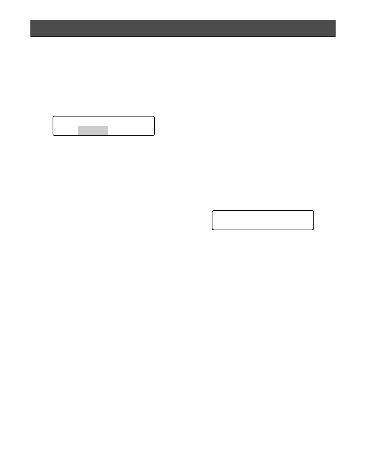
54
■ System Controller Behavior during the Alarm Mode
When an alarm signal is input to cameras or system units,
this system controller is notified that an alarm has been
activated. Then, the ALARM indicator will blink. During the
alarm mode, “Alarm” sign will blink on the LCD, and the
camera number is displayed as “- - -“.
When an alarm is automatically canceled (=alarm auto
reset mode), “Alarm” sign changes from blinking to steady
light, and the LCD display returns to the normal status.
■ Alarm Reset
You can cancel the alarm mode (“Alarm” sign is blinking.)
or alarm auto reset mode (The ALARM indicator is lighting.). The alarm inputs to all the system units will be reset
all together.
Press ALM RESET/ALM ALL RESET button.
The alarm mode or alarm auto reset mode of all the system
units will be cancelled, and the ALARM indicator will go out.
Notes:
• Alarm behaviors differ depending on connected system
units. Refer to the operating instructions of system units.
• You cannot cancel the alarm mode or alarm auto reset
mode of each system unit one by one.
■ Alarm Suspension
You can temporarily stop alarm inputs to all the system
units in the following procedure.
1. Press the ALARM/ALM SUSPEND button while holding
down the SHIFT button.
The alarm inputs will be suspended and the ALM SUSPEND indicator will light up.
2. To cancel the alarm suspension mode, press
ALARM/ALM SUSPEND button again while holding
down the SHIFT button. The alarm suspension mode
will be canceled, and the ALM SUSPEND indicator will
go out.
Note: You cannot suspend each alarm input one by
one. The alarm inputs to all the system units will be
suspended all together.
■ Alarm History Search
To play back a desired alarm image, the alarm history table
of selected system unit can be displayed. The following
procedure is available when the selected system unit can
display the alarm history table.
Note: WJ-HD300 Series does not support alarm history
search.
● How to Display Alarm History Tables
1. Press the ALM RECALL button.
“Alarm Recall” sign will appear on the LCD, and the
alarm history table will be displayed on an active monitor.
2. Perform operations while watching the active monitor.
Note: The operation details differ depending on
recorders. Refer to pp. 55 to 56.
Controls commonly available
<Main unit>
Shuttle ring clockwise:
• Moves to the next page.
• Moves the cursor. (Available for WJ-HD500 or WJ-
HD200 Series)
Shuttle ring counterclockwise:
• Moves to the previous page.
• Moves the cursor. (Available for WJ-HD500 or WJ-
HD200 Series)
JogDial clockwise or counterclockwise:
• Moves the cursor.
• Changes the selected parameter. (Available for WJ-
HD500 or WJ-HD200 Series)
+ button: Increases a numeric value.
– button: Decreases a numeric value.
Numeric buttons: Enters numeric parameters.
CAM (SET) button: Determines the selected parame-
ter.
MON (ESC) or EXIT button: Closes the search list dis-
play.
ALARM CONTROL
Mon01 Cam--- HD316
Alarm
Alarm Recall
Page 55
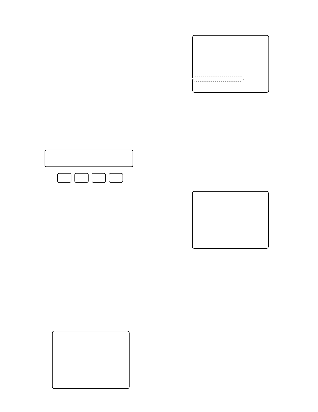
55
<Joystick unit>
3D joystick upward (▲): Moves the cursor up.
3D joystick downward (▼): Moves the cursor down.
3D joystick to the left (t): Moves the cursor to the left.
3D joystick to the right (s): Moves the cursor to the
right.
Zoom wheel controller to the right or left: Changes
the search list display. (For example, Record list ↔
Thumbnail Display ↔ Record List …)
Top button: Determines the selected parameter.
Note: Depending on recorder types, you can press the
function buttons (F1 to F8) to activate the search function. The following are the details on LCD display patterns and function buttons of WJ-HD500, WJ-HD300,
and WJ-HD100 Series recorders.
● Operation (WJ-HD500 Series)
Available buttons and functions
F1 button: Edit
You will press this button when editing the Search
Editing Area on the Record List.
F2 button: Group
The selected group is switched by rotation.
F4 button: Copy
The selected recording images will be copied to a
external recording device (DVD or CD-R).
Note: Refer to the operating instructions of recorder for
details on each function.
Example of F1 button use
1. Display the Alarm and Emergency Record List on the
active monitor. (Refer to Step 1 in p. 54 How to Display
Alarm History Tables.)
2. Press the F1 button.
Search Editing Area will appear on the Record List.
3. Move the cursor to a position to be edited by performing either of the following.
• Move the 3D joystick controller to the right or left.
• Rotate the shuttle ring clockwise or counterclock-
wise.
4. Enter the desired date and time by performing either of
the following.
• Rotate the JogDial clockwise or counterclockwise.
• Press the + or – button.
5. Repeat Step 3 and 4 to edit Search Editing Area.
6. After editing, press the CAM (SET) button.
The associated record will be displayed on the Record
List.
7. To close the Alarm and Emergency Record List , press
the ALM RECALL, EXIT, or MON (ESC) button.
DATE MAY29.00
GROUP NO TIME
010008
G1 22:15:40 M/S ALM-TRM12
010007
G3
ALL
010005
010004
G4
G3
010002
MAY29.00SEARCH: 0:01 G1
SEL:←→ CHG:+– EXE:SET ESC:FSTOP
Search Editing Area
21:00:07
7:23:11
6:59:44
0:01:28
ALL GROUP
REC-MODE
O/S ALM-VMD3
T/L EMR
M/S ALM-PC4
T/L ALM-TRM1
2343RECORD)(TOTAL
Alarm Recall HD500
Edit Group Copy
F1 F2 F3 F4
DATE MAY29.00
GROUP NO TIME
010008
G1 22:15:40 M/S ALM-TRM12
G3
010007
ALL
010005
010004
G4
G3
010002
MAY29.00SEARCH: 9:31 ALL GROUP
SEL:←→ CHG:+– EXE:SET ESC:FSTOP
21:00:07
7:23:11
6:59:44
0:01:28
ALL GROUP
REC-MODE
O/S ALM-VMD3
T/L EMR
M/S ALM-PC4
T/L ALM-TRM1
2343RECORD)(TOTAL
DATE MAY29.00
GROUP NO TIME
010008
G1 22:15:40 M/S ALM-TRM12
010007
G3
ALL
010005
010004
G4
G3
010002
PLAY:B ESC:FSTOP SEL:JOG
SEARCH:DISPLAY
21:00:07
7:23:11
6:59:44
0:01:28
ALL GROUP
REC-MODE
O/S ALM-VMD3
T/L EMR
M/S ALM-PC4
T/L ALM-TRM1
2343RECORD)(TOTAL
Page 56
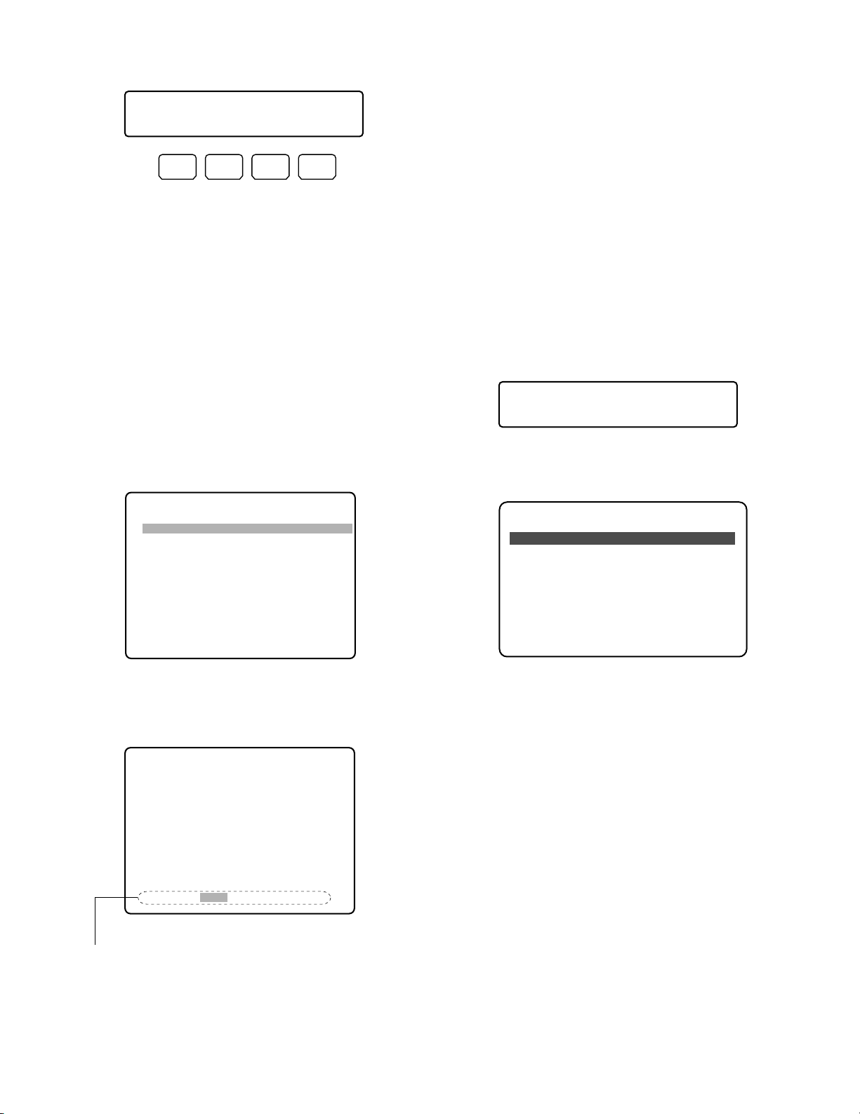
56
● Operation (WJ-HD200 Series)
Note: WJ-HD200 Ver. 1.24 later or WJ-HD220 supports
alarm history search. (Refer to the operating instructions of recorder.)
Available buttons and functions
F1 button: Edit
You will press this button when editing the Search
Editing Area on the ALARM RECALL window.
Note: Refer to the operating instructions of recorder for
details.
Example of F1 button use
1. Press the ALM RECALL button. The ALARM RECALL
window will be displayed on the active monitor.
2. Press the F1 button. Search Editing Area will appear on
the ALARM RECALL window.
3. Move the cursor to a position to be edited by performing either of the following.
• Move the 3D joystick controller to the right or left.
• Rotate the shuttle ring clockwise or counterclock-
wise.
4. Enter the desired date and time by performing either of
the following.
• Rotate the JogDial clockwise or counterclockwise.
• Press the + or – button.
5. Repeat Step 3 and 4 to edit Search Editing Area.
6. Press the CAM (SET) button. The specified playback
image will be displayed on the monitor.
7. To close the ALARM RECALL window, press the ALM
RECALL, EXIT, or MON (ESC) button.
● Operation (WJ-HD100 Series)
1. Press the ALM RECALL button. The ALARM RECALL
window will be displayed on the active monitor.
2. Move the cursor to a position to be edited by performing either of the following.
• Move the 3D joystick controller to the right or left.
• Rotate the JogDial clockwise or counterclockwise.
3. Enter the desired date and time by performing either of
the following.
• Rotate the JogDial clockwise or counterclockwise.
• Press the + or – button.
4. Press the CAM (SET) button. The specified playback
image will be displayed on the monitor.
5. To close the ALARM RECALL window, press the ALM
RECALL, EXIT, or MON (ESC) button.
Notes:
• You will use no function buttons for controlling the
recorder.
• Image to be played back differs depending on
recorders. (Refer to the operating instructions of
recorder.)
Alarm Recall HD200
Edit
F1 F2 F3 F4
ALARM RECALL YEAR03
NO. DATE TIME ALM
2000 JUN14 20:30:00 T1
1999 JUN14 15:30:12 T3
1998 JUN14 12:15:04 T4
1997 JUN14 12:15:02 V8
1996 JUN14 10:07:05 V2
1995 JUN14 10:07:04 T2
1994 JUN14 10:06:55 T6
1993 JUN14 09:58:32 V5
(TOTAL 2000EVENTS)
TO SEARCH PUSH T&D KEY
Alarm Recall HD100
ALARM RECALL 1 OF 10
NO DATE TIME ALM
99 JUN 9.00 00:00:00 * T
98 JUN 1.00 02:34:56 T
97 JUN 1.00 01:10:01 * V
96 MAY31.00 23:34:45 V
95 MAY30.00 02:00:20 * T
94 MAY14.00 05:30:31 * T
93 MAY 7.00 23:00:59 T
92 MAY 6.00 22:05:50 V
91 APR14.00 23:00:59 * T
90 APR14.00 16:06:34 * V
ALARM RECALL YEAR03
NO. DATE TIME ALM
2000 JUN14 20:30:00 T1
1999 JUN14 15:30:12 T3
1998 JUN14 12:15:04 T4
1997 JUN14 12:15:02 V8
1996 JUN14 10:07:05 V2
1995 JUN14 10:07:04 T2
1994 JUN14 10:06:55 T6
1993 JUN14 09:58:32 V5
(TOTAL 2000EVENTS)
SEARCH JUN14.03 12:00
Search Editing Area
Page 57
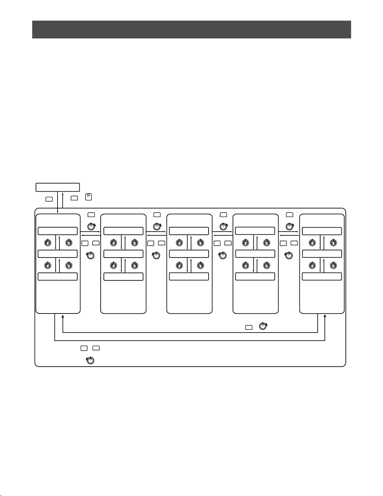
57
MENU FUNCTION DESCRIPTIONS
You can assign frequently-used menu functions (system functions and camera functions, etc.) to the F1 to F8 button of system
controller. (=Button function) In addition, you can also assign the menu functions to the A, B and top buttons of 3D joystick
unit. (=Joystick button function) Only by pressing an associated button, you can recall the assigned button functions and joystick functions.
Note: For details, refer to p. 63 To Assign Menu Functions to Function Buttons or p. 63 To Assign Menu Functions to Joystick
Function Buttons.
■ Menu Flow
When you press the MENU button during normal operation, menu functions are displayed on the LCD. The menu functions are
classified according to the function types (camera functions, recorder functions, and system functions, etc.)
(Refer to p. 58 Menu Function Categories.)
Normal status
Mon04 Cam128 HD316
F1 F2 F3 F4
MENU
Camera Functions
(CAM)
LCD MENU CAM 101
Camera Setup
LCD MENU CAM 102
Auto Mode
EXIT
•
N
O
M
or
(ESC)
• 60 seconds after the operation is discontinued
SHIFT
MENU
or
Recorder Functions
LCD MENU HDD 201
HD300 DiskSelect
MENU
+
or
LCD MENU HDD 202
HD300 A-B Repeat
(HDD)
SHIFT
MENU
or
MENU
+
or
System Functions
(SYS)
LCD MENU SYS 301
System Setup
LCD MENU SYS 302
Switcher OSD
MENU
Controller Functions
or
LCD MENU CNT 401
Camera Cleaning
MENU
SHIFT
+
or
LCD MENU CNT 402
Time&Date Type
(CNT)
SHIFT
MENU
or
Joystick Functions
J/S MENU 501
Camera Function
MENU
+
or
J/S MENU 502
System Function
(J/S MENU)
LCD MENU CAM 103
BW Mode
•
•
•
•
•
SHIFT
MENU
+
or
LCD MENU HDD 203
HD300 Listed
•
•
•
•
•
LCD MENU SYS 303
VLD History
•
•
•
•
•
LCD MENU CNT 403
Auto Login
•
•
•
•
•
MENU
or
J/S MENU 503
Auto Pan
•
•
•
•
•
Page 58
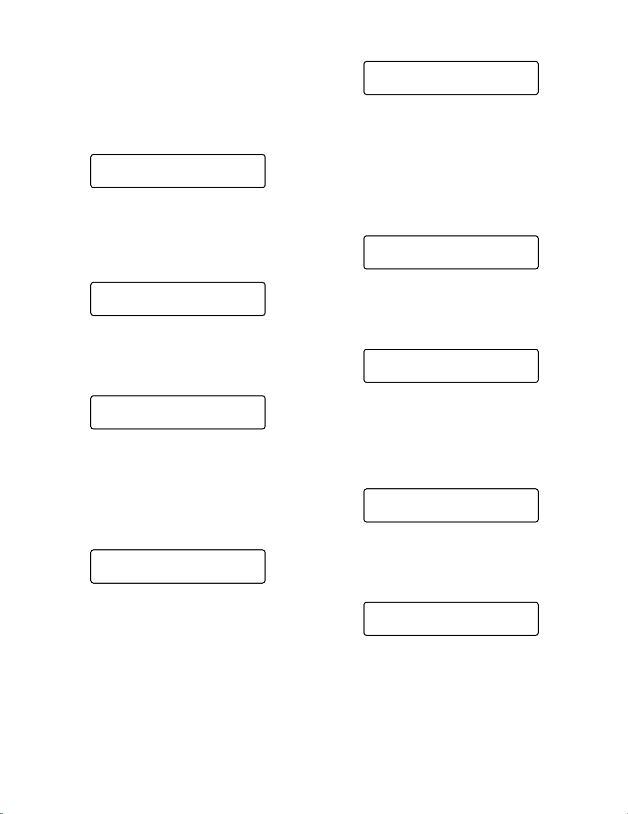
58
Auto Pan Setup
You will perform the auto pan setting of camera.
Note: Refer to the operating instructions of camera for
details on the auto pan function.
● Recorder Functions (HDD)
HD300 Disk Select (WJ-HD300 Series only)
You will select the built-in hard disk or an external recording
devices for playback by WJ-HD300 Series.
HD300 A-B Repeat (WJ-HD300 Series only)
• You will set the start and end points of A – B repeat
playback of WJ-HD300 Series.
• You will cancel A – B repeat playback of WJ-HD300
Series.
HD300 Listed (WJ-HD300 Series only)
You will cancel, recover, or temporarily cancel the searching filter of WJ-HD300 Series.
HD500 V-Multi (WJ-HD500 Series only)
You will select a playback picture to display on the upper
left segment of the multiscreen monitor displaying live
images.
■ Menu Function Categories
Menu functions are classified in the following categories.
Select a desired function for assignment or operation.
● Camera Functions (CAM)
Camera Setup
• This function displays or closes the camera setup menu
for system settings.
• You will change camera settings.
Auto Mode
You will select and activate one of the auto mode functions
of camera: sequence, sort, auto pan and patrol.
BW Mode
You will select and activate one of the color modes: MANUAL ON, MANUAL OFF, AUTO 1, and AUTO 2.
Note: Refer to the operating instructions of camera for
details on the BW mode.
Patrol Learn
You will perform the patrol learn setting of camera.
LCD MENU CAM 105
Auto Pan Setup
LCD MENU CAM 101
Camera Setup
LCD MENU CAM 102
Auto Mode
LCD MENU CAM 103
BW Mode
LCD MENU HDD 201
HD300 DiskSelect
LCD MENU HDD 202
HD300 A—B Repeat
LCD MENU CAM 104
Patrol Learn
LCD MENU HDD 203
HD300 Listed
LCD MENU HDD 204
HD500 V—Multi
Page 59
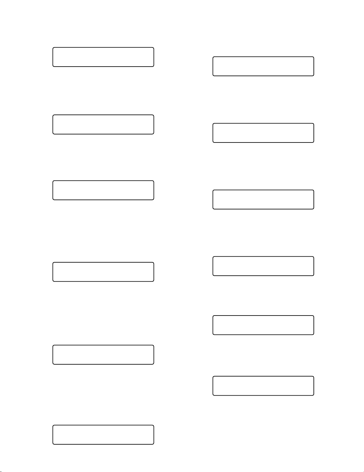
59
● System Functions (SYS)
System Setup
You will open the setup menu of system unit and change
the settings.
Switcher OSD (WJ-SX150 Series only)
Displays or hides the OSD items displayed on monitors
connected to the matrix switcher.
VLD History (WJ-SX150 Series only)
Displays the VIDEO LOSS HISTORY table on monitors connected to the matrix switcher.
Mux VCR/CAM (Available if Video Multiplexer
WJ-FS416 or Multiplexer Board WJ-SXB151 is
Used in the System)
You can activate either VCR playback or camera picture
display on an active monitor.
Mux Still (Available if Video Multiplexer WJFS416 or Multiplexer Board WJ-SXB151 is
Used in the System)
You can activate either still or moving mode for display on
the multiscreen monitor.
● Controller
Camera Cleaning
You will select the first and last camera channel to perform
camera cleaning.
Time & Date Type
You will set the time and date display pattern of time-anddate entry form.
Auto Login/Logout
You will set operators who can log into the system automatically.
Operator Setup
• You will register a new operator.
• You will change parameters of registered operators.
Function Level
You will change the function levels of operators.
Camera Level
You will change the camera control levels of operators.
Cam Posi Map
You will register camera positions (the association of camera numbers and preset position numbers).
LCD MENU SYS 301
System Setup
LCD MENU SYS 302
Switcher OSD
LCD MENU SYS 303
VLD History
LCD MENU CNT 402
Time&Date Type
LCD MENU CNT 403
Auto Login/out
LCD MENU CNT 404
Operator Setup
LCD MENU SYS 304
Mux VCR/CAM
LCD MENU SYS 305
Mux Still
LCD MENU CNT 401
Camera Cleaning
LCD MENU CNT 405
Function Level
LCD MENU CNT 406
Camera Level
LCD MENU CNT 407
Cam Posi Map
Page 60

60
Cam-Unit Map
You will register cam-unit maps (the association of camera
numbers and unit numbers).
HDD-Unit Map
You will register HDD-unit maps (the association of
recorder numbers and unit numbers).
LCD Title
You will edit the function names of F1 to F8, which are displayed on the LCD.
●
Joystick Button Functions (J/S MENU)
Camera Function
A camera function will be activated.
System Function
A system function will be activated.
Auto Pan
The auto pan function of selected camera will be activated.
Camera Sequence
The camera sequence function of selected camera will be
activated.
Camera Sort
The camera sort function of selected camera will be activated.
Patrol Play
The patrol function of selected camera will be activated.
Home Position
The selected camera will move to the home position.
Auto Focus
The “Auto Focus” function of selected camera will be activated.
Iris Reset
The lens iris of selected camera will be automatically reset
to the factory default.
LCD MENU CNT 408
Cam-Unit Map
LCD MENU CNT 409
HDD-Unit Map
LCD MENU CNT 410
LCD Title
J/S MENU 504
Camera Sequence
J/S MENU 505
Camera Sort
J/S MENU 506
Patrol Play
J/S MENU 501
Camera Function
J/S MENU 502
System Function
J/S MENU 503
Auto Pan
J/S MENU 507
Home Position
J/S MENU 508
Auto Focus
J/S MENU 509
Iris Reset
Page 61
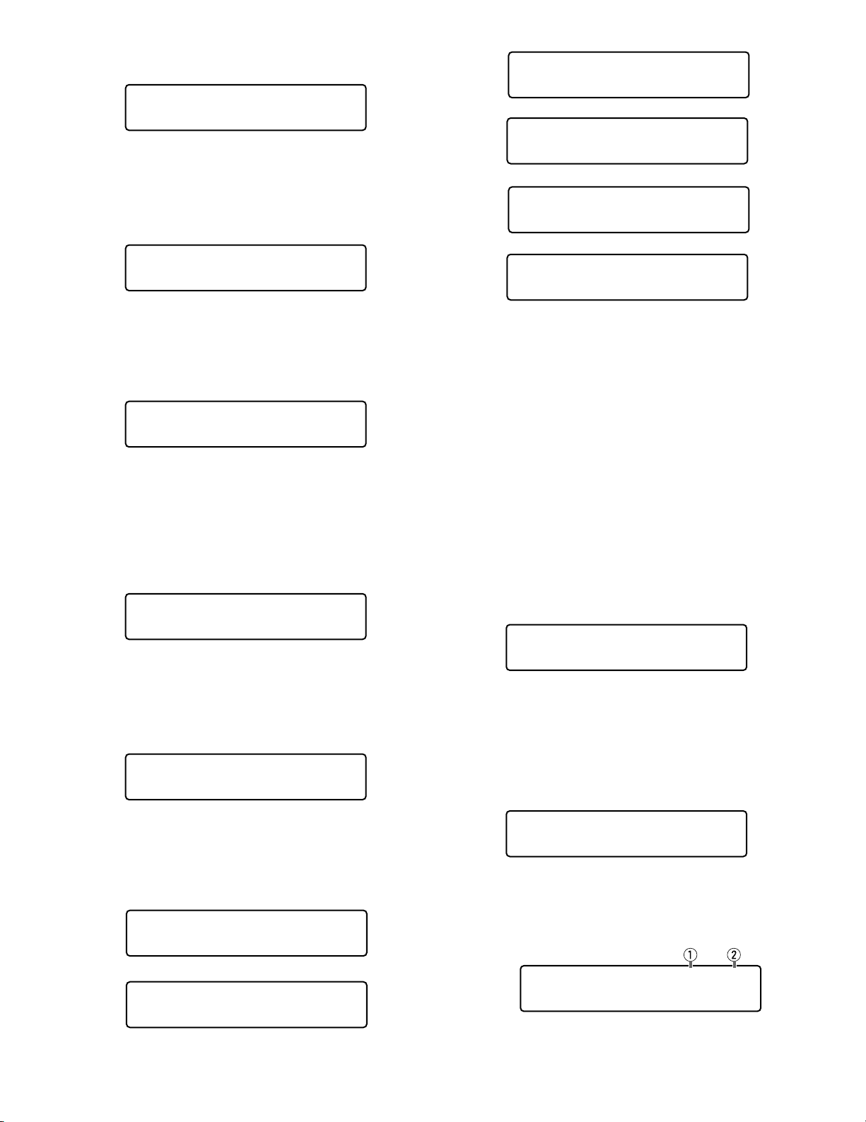
61
Camera +1
The image of camera with the higher channel number will
be displayed.
Camera –1
The image of camera with the lower channel number will be
displayed.
HD300 A-B Repeat (WJ-HD300 Series Only)
• You will set the start and end points of A – B repeat
playback of WJ-HD300 Series.
• You will cancel A – B repeat playback of WJ-HD300
Series.
HD500 Copy (WJ-HD500 Series Only)
Recorded images will be copied from the built-in hard disk
of recorder to external recording devices.
HD200 Alarm Search (WJ-HD200 Series Only)
The alarm search function of recorder will be activated.
Multiscreen Display
The screen of monitor connected to the selected system
unit will be divided in multiscreen segments.
Note: Available multiscreen segment patterns differ
depending on system units. Refer to the operating
instructions of system units.
■ To Recall Menu Functions
You can recall menu functions as follows.
1. Select a system unit for which you wish to recall a function. (Refer to p. 41 System Unit Selection, p. 41
Recorder Selection, p. 42 Monitor Selection, or p. 42
Camera Selection.)
Note: You can skip Step 2 and 3 if you know what func-
tion to recall. In this case, enter a function number,
and press the MENU button. Then, go to Step 4.
2. Press the MENU button.
“Camera Setup” main menu will appear on the LCD.
3. Select a desired function.
Select a category (q) by rotating the shuttle ring. Then,
select a function number (w) by rotating the JogDial.
Note: Refer to pp. 58 to 61 for selectable functions.
J/S MENU 510
Camera +1
J/S MENU 517
Multi 9-Seg
J/S MENU 518
Multi 10-Seg
J/S MENU 511
Camera -1
J/S MENU 512
HD300 A—B Repeat
J/S MENU 513
HD500 Copy
J/S MENU 519
Multi 13-Seg
J/S MENU 520
Multi 16-Seg
Mon01 Cam016 HD316
F1 F2 F3 F4
J/S MENU 514
HD200 Alm Search
J/S MENU 515
Multi 4-Seg
J/S MENU 516
Multi 7-Seg
LCD MENU CAM 101
Camera Setup
LCD MENU SYS 301
System Setup
Page 62
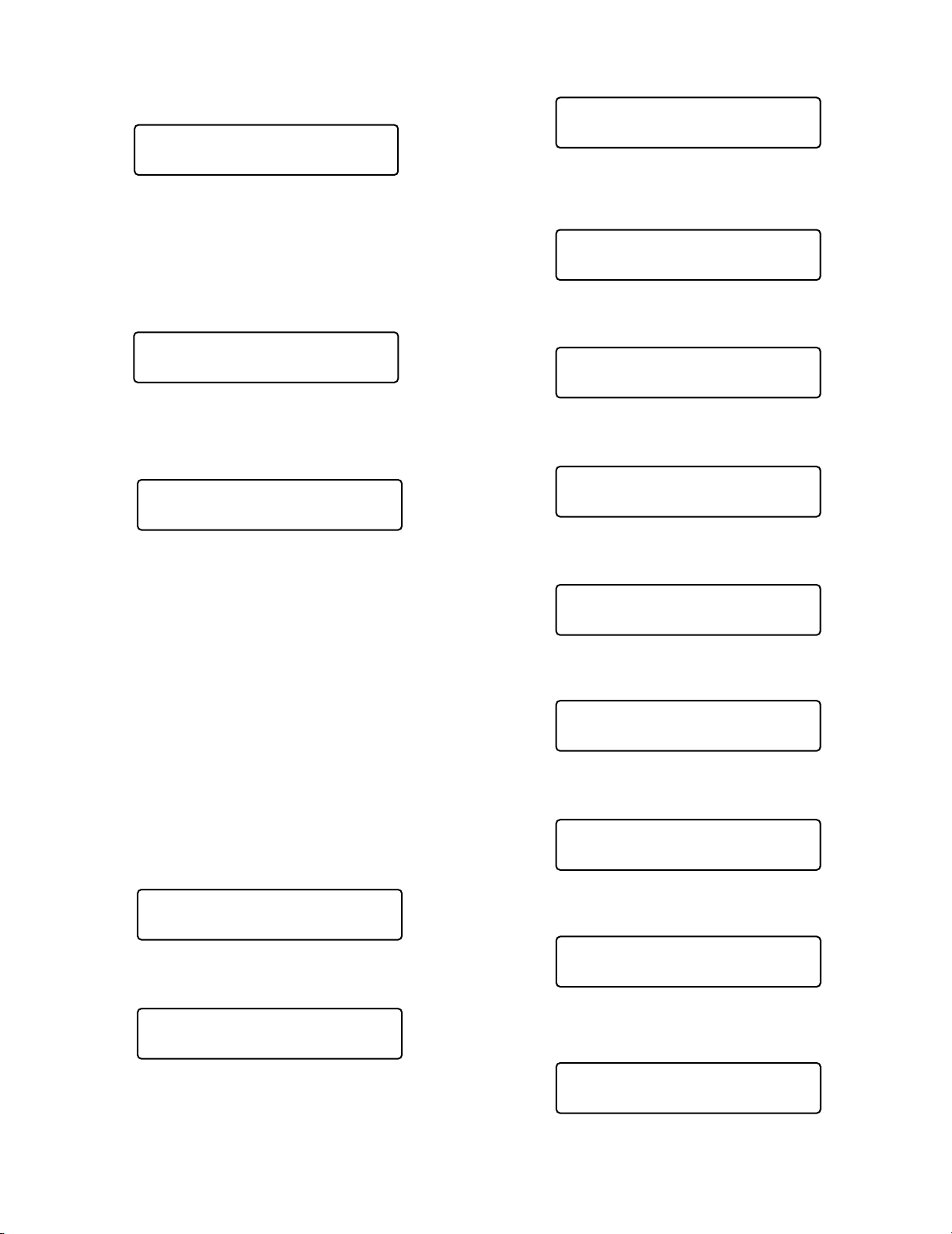
62
4. Press the ENTER or CAM (SET) button.
The sub menu of selected function will appear on the
LCD.
5. Perform the operations to activate the selected function.
The operating procedure differs depending on each
function. Refer to pp. 65 to p. 84.
6. To exit the sub menu, press the EXIT or MON (ESC)
button. The LCD display will return to the main menu.
7. To exit the main menu, press the EXIT or MON (ESC)
button again. The LCD display will return to the default
status.
■ Factory Default Setting of Button Functions and Joystick Button Functions
The following functions have been assigned to the function
(F1 to F8) buttons and joystick function (A, B, and top) buttons.
Note: To change the default assignments, refer to p. 63 To
Assign Menu Functions to Function Buttons or p. 63. To
Assign Menu Functions to Joystick Function Buttons.
F1: Camera Setup
F2: Auto Mode
F3: BW Mode
F4: Patrol Learn
F5 (SHIFT + F1): System Setup
F6 (SHIFT + F2): HD300 A – B Repeat
F7 (SHIFT + F3): HD300 Listed
F8 (SHIFT + F4): HD300 Disk Select
A: Iris Reset
B: Auto Focus
Top: Auto Focus
System Setup 301
On Off
BW Mode F3
On Off Auto1 Auto2
LCD MENU SYS 301
System Setup
Mon01 Cam016 HD316
F1 F2 F3 F4
Patrol Learn F4
Start Stop
System Setup F5
On Off
HD300 A—B Repeat F6
Start End Cancel
HD300 Listed F7
On Off
HD300 DiskSelect F8
Nr-A Cp–A Cpy1 Cpy2
Camera Setup F1
On Off Rst A.Rst
Auto Mode F2
Seq Sort Pan Patrol
Iris Reset A
Auto Focus B
Auto Focus J/S
Page 63
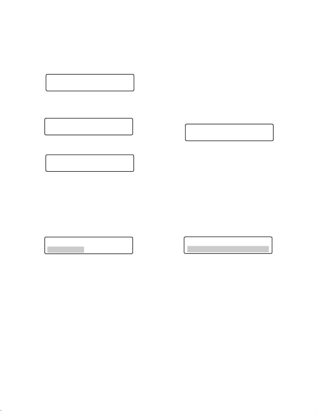
63
■ To Assign Menu Functions to
Function Buttons
All menu functions are assignable to the function (F1 to F8)
buttons. (Refer to pp. 65 to 84 for each function.)
1. Press the MENU button.
“Camera Setup” main menu will appear on the LCD.
2. Select a desired function.
Select a desired category by rotating the shuttle ring.
3. Select a function name by rotating the JogDial.
• You can skip Step 2 if you know what function to
recall. In this case, enter a function number, and
press the ENTER button.
4. Press the function button you wish to assign the function for two seconds. The function will be assigned to
the button, and the message will appear for a few seconds.
Notes:
• To assign menu functions to F5 to F8 buttons, press
one of the F1 to F4 buttons for two seconds while
holding down the SHIFT button.
• The setting procedure differs depending on each
function. Refer to pp. 65 to 84.
5. To exit the menu, press the EXIT or MON (ESC) button.
The LCD display will return to the default status.
■ To Assign Menu Functions to Joystick Function Buttons
Joystick button functions are assignable to the A, B, or top
button on the 3D joystick unit. (Refer to p. 80 to 84 for each
function.)
1. Perform Step 1 to 3 in To Assign Menu Functions to
Function Buttons.
Note: Skip the next step when assigning neither
“Camera Function” nor “System Function”.
2. Enter a desired camera or system function number with
the numeric buttons. The entered number will appear
on the LCD for a few seconds.
Notes:
• The illustration is an example in which Camera
Function Number 1 is pressed.
• Refer to the operating instruction of camera for
details on camera function.
• Refer to the operating instruction of system unit for
details on system function.
3. Press the A, B or top button for two seconds.
• The menu function will be assigned to the button
you pressed.
•“Assign” message will appear for a few seconds, as
shown in the illustration.
Note: The illustration is an example in which “Camera
Function Code = 1” has been assigned to the A
button.
4. To exit the menu, press the EXIT or MON (ESC) button.
The LCD will return to the normal display.
LCD MENU CAM 101
Camera Setup
LCD MENU SYS 301
System Setup
LCD MENU SYS 305
Mux Still
J/S MENU ____1
Camera Function
Mux Still 305
Assign F2
Camera Function 501
Assign A Code= 1
Page 64
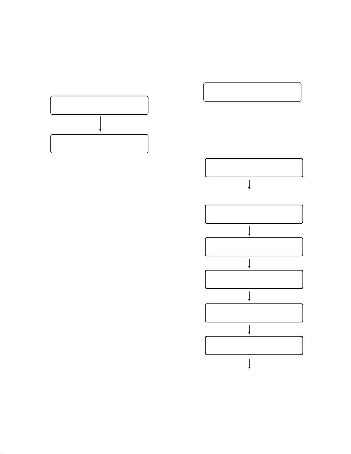
64
■ To Recall Button Functions and Joystick Button Functions
You can recall the assigned button functions and joystick
button functions as follows.
1. Press
one of the function buttons (F1 to F4/F5 to F8) or
one of the joystick function buttons (A, B, and top buttons). The sub menu of recalled function will appear on
the LCD.
Note: To recall a function assigned to the F5 to F8 but-
ton, press the function button while holding down
the SHIFT button.
2. Perform the operations to activate the function.
The operating procedure differs depending on each
function. Refer to pp. 65 to 84.
Note: To cancel the function, press the EXIT or MON
(ESC) button. The LCD display will return to the normal status.
■ To Check Button Functions and Joystick Button Functions
You can check the functions assigned to the function (F1 to
F8) buttons and joystick function (A, B, and top) buttons.
1. Press the MENU button while holding down the SHIFT
button. The F1 button function will appear on the LCD.
Note: This illustration is an example in which “Camera
Setup” is assigned to the F1 button.
2. To check other (joystick) button functions, rotate the
JogDial. The button functions and joystick button function will appear on the LCD in the following order.
3. To finish checking the function, press the EXIT or MON
(ESC) button.
The LCD will return to the normal status.
Mon02 Cam128 HD316
F1 F2 F3 F4
Camera Setup F1
On Off Rst A.Rst
Function Check F1
Camera Setup 101
Function Check F1
Camera Setup 101
•
•
Function Check F8
System Setup 301
Function Check A
Cam Func "4096" 501
Function Check B
Sys Func "999" 502
Function Check J/S
Auto Focus 506
Function Check F1
Camera Setup 101
•
•
Page 65
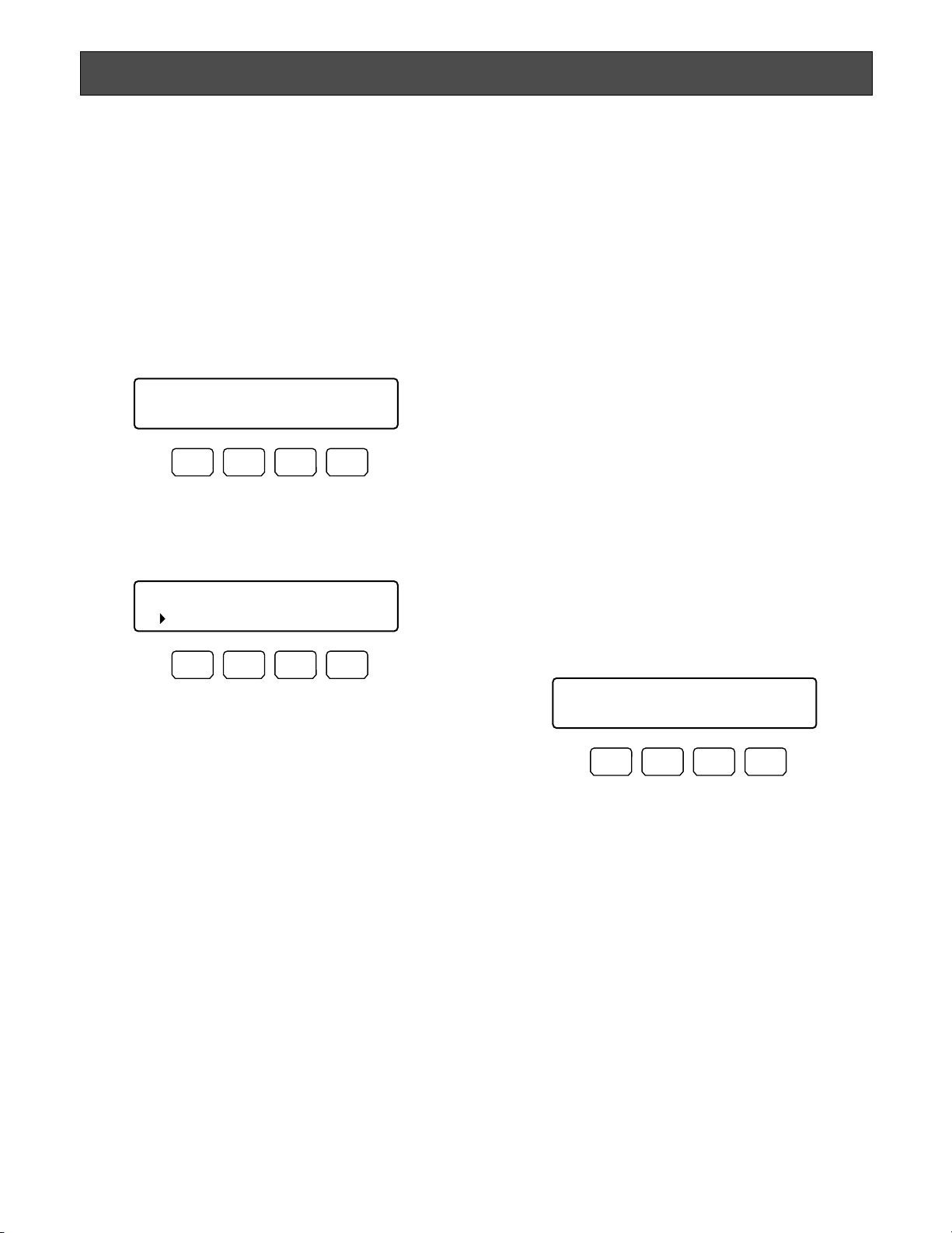
65
MENU FUNCTION DETAILS
■ Camera Functions
● Camera Setup
You can display the setup menu of selected camera on the
active monitor.
Note: The details on the setup menu differ depending on
camera models. Refer to the operating instructions of
camera.
1 .Display “Camera Setup” sub menu. (Refer to Step 1 to
4 of p. 61 To Recall Menu Functions.)
2. Press the F1 button.
The setup menu of selected camera will appear on the
active monitor, and “s” mark will light up beside “On”.
3. Perform the camera setting while watching the setup
menu on the monitor.
Available controls and functions
<Main unit>
JogDial clockwise or counterclockwise: Changes the
selected parameter.
+ button: Increases a numeric value.
– button: Decreases a numeric value.
CAM (SET) button: Determines the selected parameter
and moves to the sub menu.
MON (ESC) or EXIT button: Returns to the upper
menu.
F3 button:
• Displays the special menu.
• To restore the default camera position, move the
cursor to REFRESH on the camera setup menu by
moving the 3D joystick. Then, press this button.
F4 button: To reset all the camera settings to the facto-
ry default, move the cursor to CAMERA RESET on
the camera setup menu by moving the 3D joystick.
Then, press this button.
<Joystick unit>
3D joystick upward (▲): Moves the cursor up.
3D joystick downward (▼): Moves the cursor down.
3D joystick to the left (t):
• Decreases a numeric value.
• Moves the cursor to the left.
3D joystick to the right (s):
• Increases a numeric value.
• Moves the cursor to the right.
3D joystick + SHIFT button: Panning/tilting control
Top button: Determines the selected parameter and
moves to the sub menu.
B button: Auto focus
4. Press the F2 button.
The setup menu of selected camera will be closed, and
“s” mark will go out.
● Auto Mode
You can activate an auto mode (auto sequence, auto sort,
auto pan, and camera patrol) for the selected camera.
Note: Refer to the operating instructions of camera for
details on auto mode.
1. Display “Auto Mode” sub menu. (Refer to Step 1 to 4 of
p. 61 To Recall Menu Functions.)
2. Select a desired function by pressing one of the F1 to
F4 buttons. Auto mode will be activated.
Available buttons and functions
F1: Seq
Activates the sequence mode.
F2: Sort
Activates the sort mode.
F3: Pan
Activates the auto pan mode.
F4: Patrol
Activates the patrol mode.
Note: Auto mode will be canceled when you pan or tilt the
selected camera by moving the 3D joystick.
Camera Setup 101
On Off Rst A.Rst
F1 F2 F3 F4
Camera Setup 101
On Off Rst A.Rst
F1 F2 F3 F4
Auto Mode 102
Seq Sort Pan Patrol
F1 F2 F3 F4
Page 66
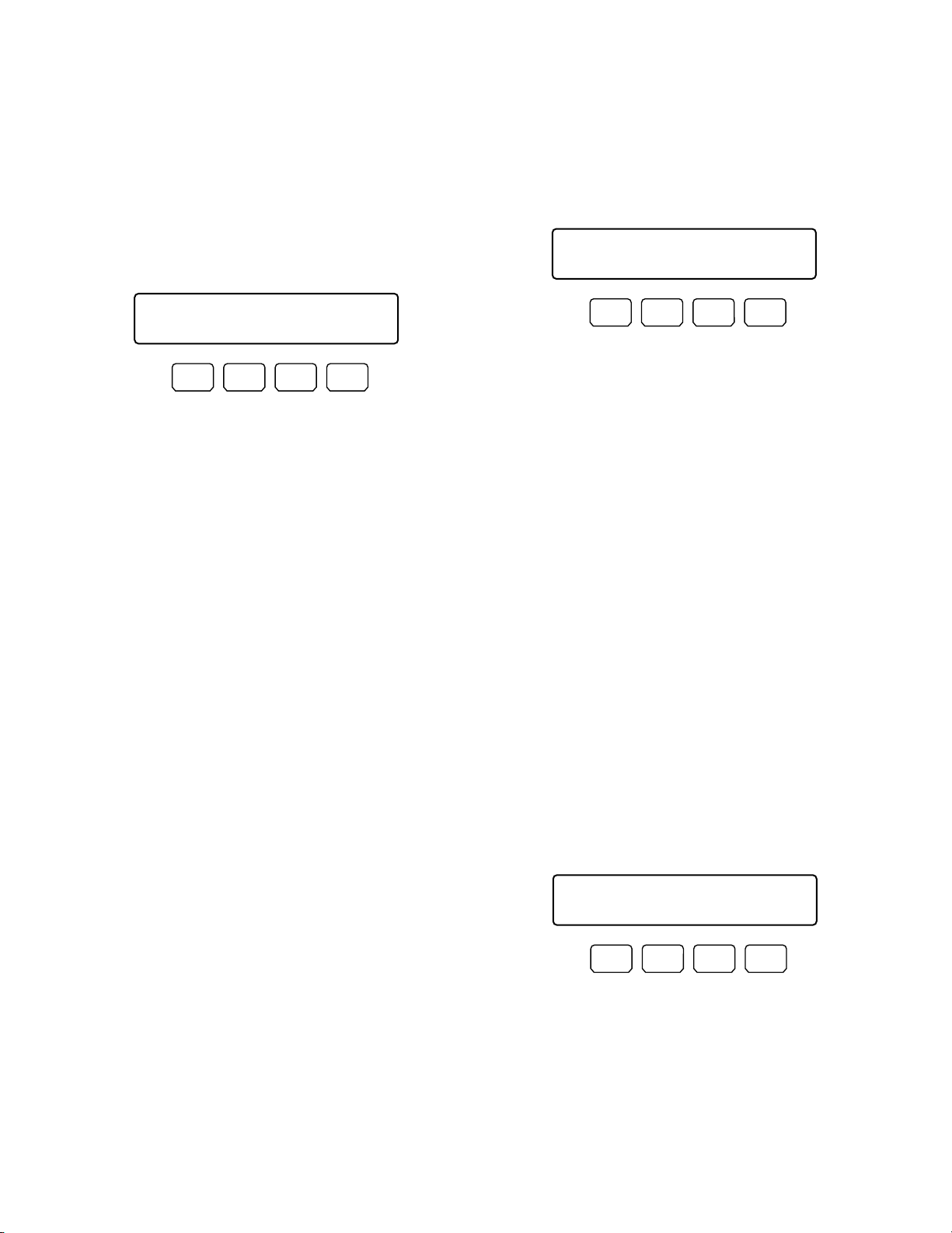
66
● BW Mode
You can change the color mode of camera images from
color to black and white. This function is activated to
improve the camera sensitivity when monitoring a dark
place.
Note: Refer to the operating instructions of camera for
details on auto mode.
1. Display “BW Mode” sub menu. (Refer to Step 1 to 4 of
p. 61 To Recall Menu Functions.)
2. Press one of the F1 to F4 buttons.
BW mode will be activated.
Available buttons and functions
F1: On
Changes the camera image from color to black and
white.
F2: Off
Changes the camera image from black and white to
color .
F3: Auto1
Activates Auto 1 mode. (The camera selects black
and white mode if the picture is dark, or color mode
if the picture is bright enough.)
F4: Auto2
Activates Auto 2 mode. (The camera detects the
light source type to prevent malfunction. This setting is applicable when using a near-infrared light
source in a dark place.)
Notes:
• The camera detects light source based on the information the CCD image pickup element receives. If an
object is continuously moving or has the same color as
the background, the object may not be properly recognized. When activating Auto 2 mode, make sure the
wavelength of light source is 800 nm or more.
• If the available parameters for selected camera are ON,
OFF, and AUTO, you can activate AUTO by pressing
the F3 button.
To recover the color mode
Press the F2 button. The color mode is recovered for the
camera image.
● Patrol Learn
You will perform the patrol learn setup.
Note: Refer to the operating instructions of camera for
details on patrol learn.
1. Display “Patrol Learn” sub menu. (Refer to Step 1 to 4
of p. 61 To Recall Menu Functions.)
2. Press the F1 button.
The patrol learn setup will start.
3. Perform desired camera operations by moving the 3D
joystick or zoom wheel controller, etc.
The following controls are available for patrol learn.
• Panning/Tilting (3D joystick)
• Iris control (IRIS OPEN/CLOSE buttons)
• Focus control (FOCUS FAR/NEAR buttons)
• Zoom control (Zoom wheel controller)
• Preset position
Note: The available total time of patrol learn differs
depending on cameras. When the time is over, the
patrol learn setup will automatically stop.
4. To quit the patrol learn setup, press the F2 button.
To activate preset positions during the patrol
learn
To move the camera to a preset position during the patrol
learn, you will perform the following operations after Step 2
of Patrol Learn.
1. Enter a preset position number.
The entered number will appear on the LCD.
Note: To cancel the entry, press the CLEAR button.
2. Press the PRESET/PGM PRESET button.
“Pre=nn” (nn is a number.) will blink on the LCD, and
the camera will move to the preset position.
BW Mode 103
On Off Auto1 Auto2
F1 F2 F3 F4
Patrol Learn 104
Start Stop
F1 F2 F3 F4
Patrol Learn ____3
Start Stop
F1 F2 F3 F4
Page 67
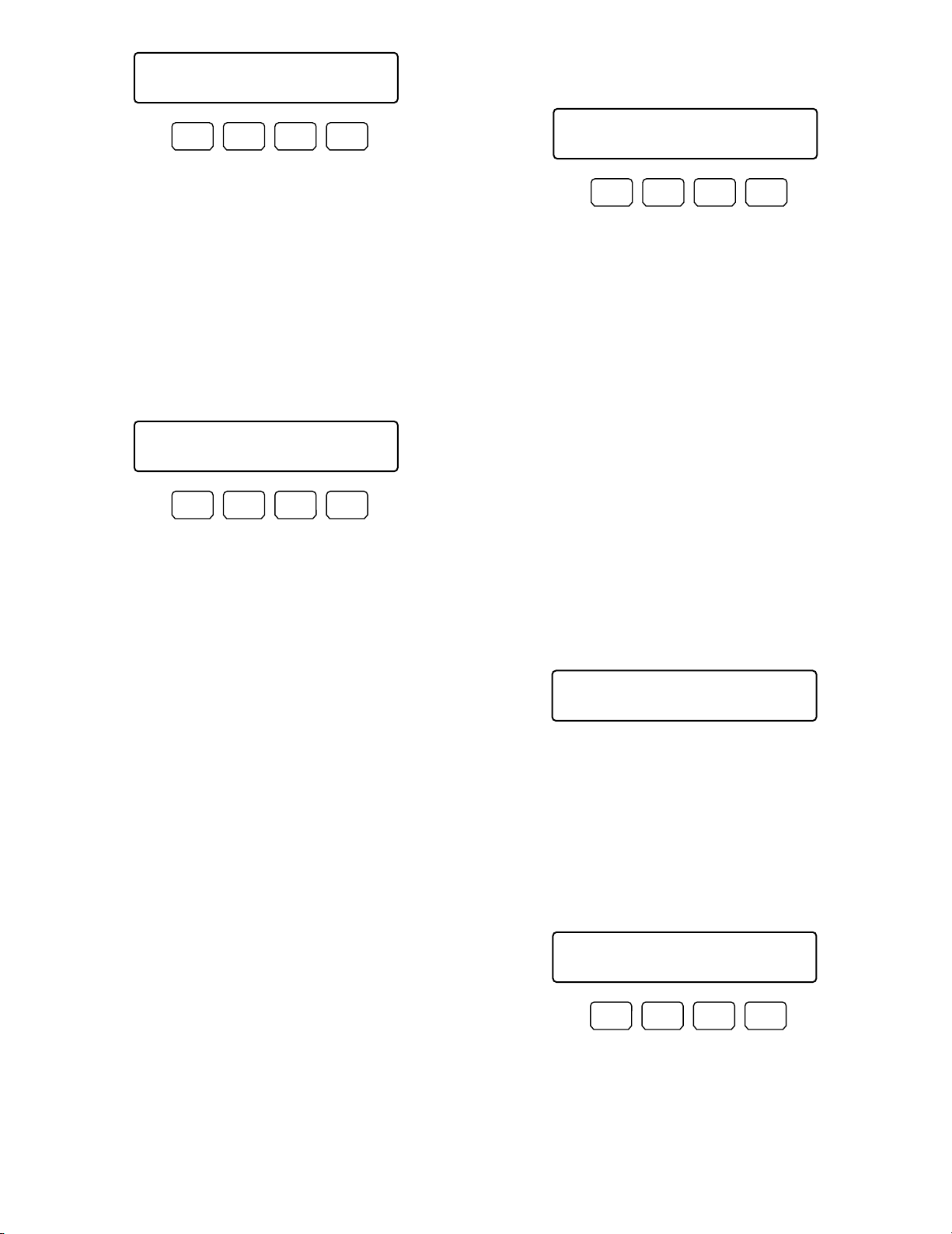
67
Note: After the camera has moved to the preset posi-
tion, “Pre-nn” will go out.
● Auto Pan Setup and Activation
You will set up and activate the auto pan function. The camera can pan between the start and end points you will set.
To set the start and end point of auto pan
1. Display “Auto Pan” sub menu. (Refer to Step 1 to 4 of p.
61 To Recall Menu Functions.)
2. By moving the 3D joystick, move the camera to a point
you wish to start auto pan.
3. Press the F3 button.
The start point of auto pan will be set.
4. By moving the 3D joystick, move the camera to a point
you wish to end auto pan.
5. Press the F4 button.
The end point of auto pan will be set.
To activate auto pan
Press the F1 button.
The auto pan will be activated, and the camera will pan
between the set.
Notes:
• If you press the F2 button, and then activate the auto
pan, the auto pan range will be reversed.
• Auto pan will be canceled when you pan or tilt the
selected camera by moving the 3D joystick.
■ Recorder Functions
● Disk Selection
(WJ-HD300 Series Only)
You will specify a disk for search playback.
1. Display “HD300 DiskSelect” sub menu. (Refer to Step 1
to 4 of p. 61 To Recall Menu Functions.)
2. Press one of the F1 to F4 buttons.
The specified disk will be selected.
Available buttons and functions
F1: Nr-A
Specifies the normal or event recording area for
playback.
F2: Cp-A
Specifies the copy area for playback.
F3: Cpy1
Specifies the external recording device connected
to COPY 1 for the playback media. (This button is
available for WJ-HD316A and WJ-HD309.)
F4: Cpy2
Specifies the external recording device connected
to COPY 2 for the playback media. (This button is
available for WJ-HD316A and WJ-HD309.)
3. When you specify a disk, the search list display will
appear on the active monitor, and “Search Mode” menu
will appear on the LCD. Then, perform the search playback operation. (Refer to p. 45 Search Playback.)
● A-B Repeat Playback Setting
(WJ-HD300 Series Only)
You can playback the recorded images repeatedly by
specifying the start point (A) and end point (B).
1. Display “HD300 A- B Repeat” sub menu. (Refer to Step
1 to 4 of p. 61 To Recall Menu Functions.)
2. During playback, press the F1 button at the point you
wish to start playback. The playback start point (A) will
be set.
Note: To cancel the start point, press the F4 button.
Patrol Learn Pre003
Start Stop
F1 F2 F3 F4
Auto Pan Setup 105
Play Rvrs Start End
F1 F2 F3 F4
HD300 DiskSelect 201
Nr-A Cp-A Cpy1 Cpy2
F1 F2 F3 F4
Search Mode HD300
Thumb Text Copy
HD300 A—B Repeat 202
Start End Cancel
F1 F2 F3 F4
Page 68
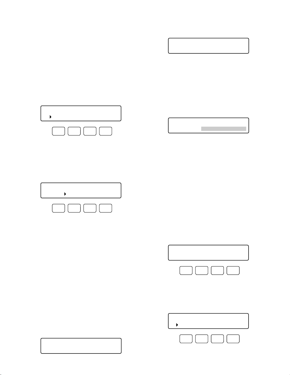
68
3. Press the F2 button at the point you wish to end playback. The playback end point (B) will be set, and the
repeat playback will be performed between (A) and (B).
Note: To quit the playback, press the STOP button.
● Filtering ON/OFF
(WJ-HD300 Series Only)
During the filtering playback, the searching filter will be
temporarily canceled or recovered.
1. Display “HD300 Listed” sub menu. (Refer to Step 1 to 4
of p. 61 To Recall Menu Functions.)
Note: Depending on the recorder status, "s" mark may
light up beside "Off.
2. Press the F2 button.
The searching filter will be canceled, and “s” mark will
light up beside “Off”.
Note: To recover the searching filter, press the F1 button.
The searching filter will be recovered, and “s” mark will
light up beside “On”.
●
Displaying Camera and Playback Image
(WJ-HD500 Series Only)
While camera images are being displayed in the multiscreen display, playback picture can be displayed on one
of the multiscreen segments. (When the spot mode is activated for the camera image on the monitor, playback picture cannot be displayed.)
Note: Refer to the operating instructions of recorder for
details on this function.
1. Display “HD500 V-Multi” sub menu. (Refer to Step 1 to
4 of p. 61 To Recall Menu Functions.)
2. Enter the channel number of camera whose playback
picture you wish to display.
The entered number will appear on the LCD.
Note: To cancel the numeric entry, press the CLEAR
button.
3. Press the F1 button.
• Playback picture will be displayed on the multiscreen monitor.
• The specified camera channel will blink on the LCD
for a few seconds, and the LCD display will return
to Step 1.
Note: To quit the playback on the multiscreen monitor,
press the STOP button.
■ System Functions
● System Setup
You can display the setup menu of selected system unit on
the active monitor.
Note: The details on the setup menu differ depending on
system units. Refer to the operating instructions of system unit.
1. Display “System Setup” sub menu. (Refer to Step 1 to 4
of p. 61 To Recall Menu Functions.)
2. Press the F1 button.
The setup menu of selected system unit will appear on
the active monitor, and “s” mark will light up beside
“On”.
HD300 Listed 203
On Off
F1 F2 F3 F4
HD500 V-Multi ____5
"Enter F1 Button"
HD500 V-Multi 204
Video CH=__5
HD300 Listed 203
On Off
F1 F2 F3 F4
System Setup 301
On Off
F1 F2 F3 F4
System Setup 301
On Off
F1 F2 F3 F4
HD500 V-Multi 204
"Input Video CH"
Page 69
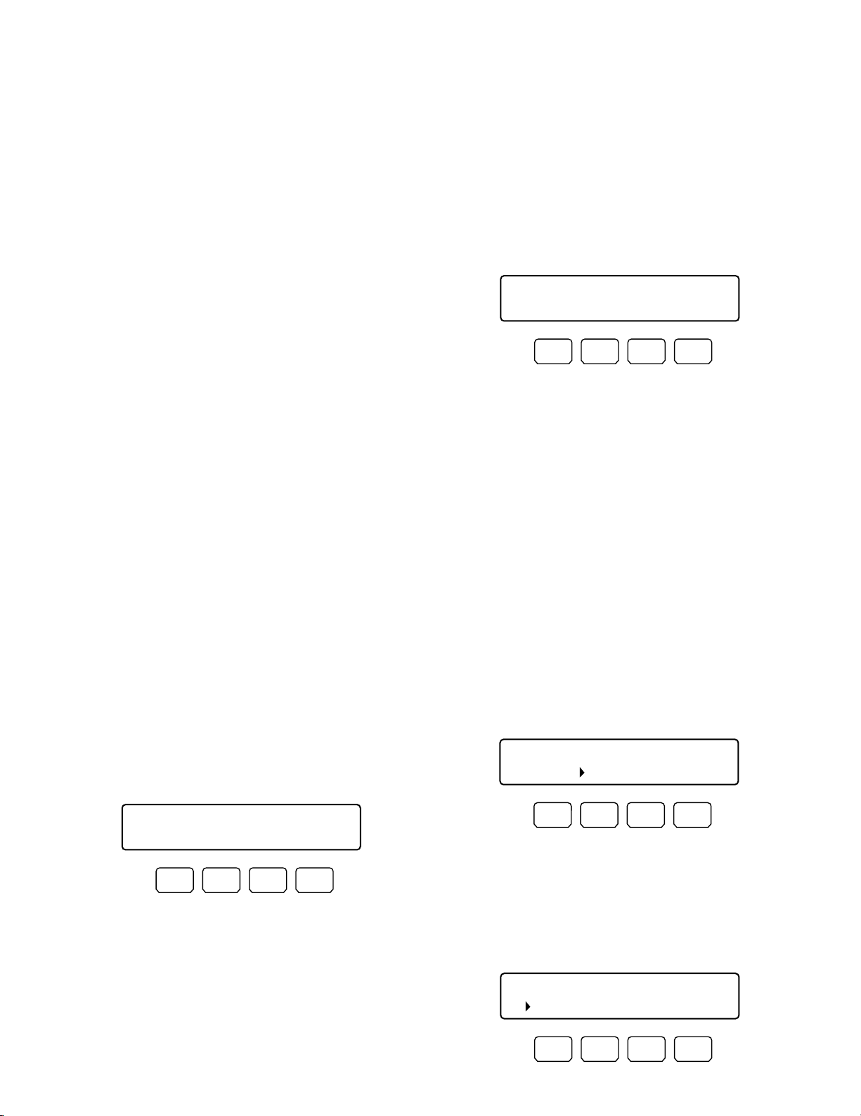
69
3. Perform the camera setting while watching the setup
menu on the monitor.
Available controls and functions
<Main unit>
Shuttle ring clockwise: Moves to the next page.
Shuttle ring counterclockwise: Moves to the previous
page.
JogDial clockwise or counterclockwise: Changes the
selected parameter.
+ button: Increases a numeric value.
– button: Decreases a numeric value.
Numeric buttons: Enters a numeric parameter.
CLEAR button (WJ-HD300 Series Only): Clears an
entry such as a password.
Button 0 (WJ-HD300 Series Only): If you enter only "0"
for a parameter, the parameter will be cleared.
CAM (SET) button: Determines the selected parameter
and moves to the sub menu.
MON (ESC) or EXIT button: Returns to the upper
menu.
<Joystick unit>
3D joystick upward (▲): Moves the cursor up.
3D joystick downward (▼): Moves the cursor down.
3D joystick leftward (t): Moves the cursor to the left.
3D joystick rightward (s): Moves the cursor to the
right.
Zoom wheel controller to the right: Moves to the next
page.
Zoom wheel controller to the left: Moves to the previ-
ous page.
Top button: Determines the selected parameter and
moves to the sub menu.
4. Press the F2 button.
The setup menu of selected system unit will be closed,
and “s” mark will light up beside “Off”.
● On-screen Display (OSD) Control
1. Display "Switcher OSD" sub menu. (Refer to Step 1 to 4
of p. 61 To Recall Menu Functions.)
2. Press one of the F1 to F4 buttons.
One of the following OSD items will appear/disappear
on/from the active monitor.
Available buttons and functions
F1: Clock
Displays/hides the time and date.
F2: Camera title
Displays/hides the camera title.
F3: Event
Displays/hides the event.
F4: Monitor status
Displays/hides the monitor status.
● Video Loss History Table
1. Display "VLD History" sub menu. (Refer to Step 1 to 4 of
p. 61 To Recall Menu Functions.)
2. Press the F1 button.
The VIDEO LOSS HISTORY table will appear on the
active monitor.
3. To close the VIDEO LOSS HISTORY table, press the F2
button.
● VCR/Camera Selection
(WJ-FS416, etc: Available Only for
Switchers Installing Multiplexer
Board)
If a Multiplexer board is installed inside the switcher, you
can activate either VCR playback or camera picture display
on an active monitor.
1. Display “Mux VCR/CAM” sub menu. (Refer to Step 1 to
4 of p. 61 To Recall Menu Functions.)
Note: “s” mark will light up beside the activated set-
ting.
2. Press the F1 or F2 button.
The monitor display will be changed between playback
pictures and live images, and “s” mark will light up
beside the activated setting.
VLD History 303
On Off
F1 F2 F3 F4
Switcher OSD 302
Clock Cam Event Mon
F1 F2 F3 F4
Mux VCR/CAM 304
VCR CAM
F1 F2 F3 F4
Mux VCR/CAM 304
VCR CAM
F1 F2 F3 F4
Page 70
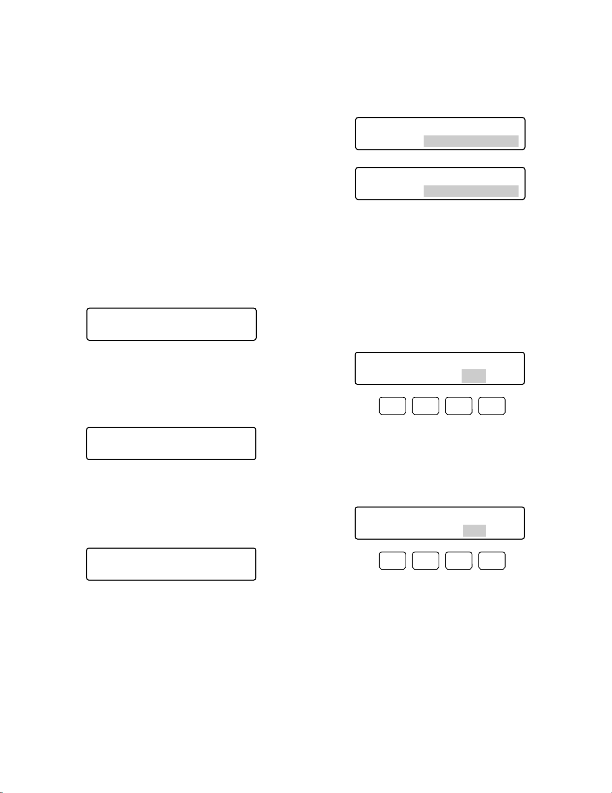
70
3. Press the F1 button.
• The still mode will be activated for the selected
camera channel.
• The specified camera channel will blink on the LCD
for a few seconds, and the LCD display will return
to Step 1.
Note: To return the multiscreen monitor display from the
still mode to moving mode, perform 1 to 3 again.
■ Controller Functions
● Camera Cleaning
1. Display “Camera Cleaning” sub menu. (Refer to Step 1
to 4 of p. 61 To Recall Menu Functions.)
2. Select the camera to clean first by performing one of
the following.
• Rotate the JogDial clockwise or counterclockwise.
• Press the + or – button.
• Enter the camera number with the numeric buttons.
3. Rotate the shuttle ring clockwise or move the 3D joystick to the right. The cursor will jump to the next item.
4. Select the camera to clean last by performing one of
the following.
• Rotate the JogDial clockwise or counterclockwise.
• Press the + or – button.
• Enter the camera number with the numeric buttons.
Available buttons and functions
F1: VCR
Activates VCR playback.
F2: CAM
Activates camera picture display.
Note: If the Multiplexer board is receiving no video
input signal, “s” mark will light up beside VCR.
● Still Mode
(WJ-FS416, etc: Available Only for
Switchers Installing Multiplexer
Board)
If a Multiplexer board is installed inside the switcher, you
can change the multiscreen monitor display from the moving mode to the still mode.
1. Display “Mux Still” sub menu. (Refer to Step 1 to 4 of p.
61 To Recall Menu Functions.)
2. Select the camera channel you wish to change to the
still mode by performing either of the following.
• Press the + or – button.
• Enter the camera number with the numeric buttons.
The entered number will appear on the LCD.
Notes:
• To cancel the numeric entry, press the CLEAR button.
• To activate the still mode for all camera channels or
spot monitor display, skip this step or enter “0”.
Mux Still 305
Still CH=__9
Mux Still 305
Still CH=All
Mux Still 305
"Input Still CH"
Mux Still ____9
"Enter F1 Button"
Mux Still ____0
"Enter F1 Button"
Camera Cleaning 401
Start Cancel 001-999
F1 F2 F3 F4
Camera Cleaning 401
Start Cancel 003-999
F1 F2 F3 F4
Page 71
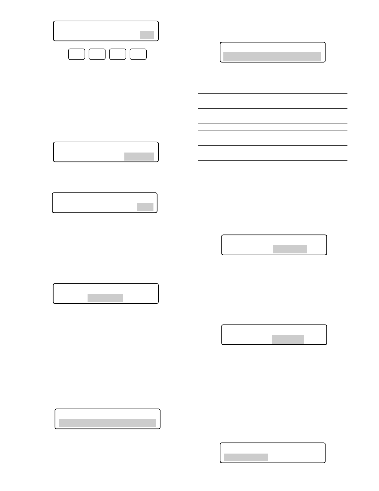
71
• Rotate the JogDial clockwise or counterclockwise.
• Press the + or – button.
The following patterns are available.
Display pattern Display Example
DD/MM/YYYY HH:MM 24 21/08/2001 22:55 24 *
2
MM/DD/YYYY HH:MM 24 08/21/2001 22:55 24
DD/Mmm/YYYY HH:MM 24 21/Aug/2001 22:55 24
YYYY/MM/DD HH:MM 24 2001/08/21 22:55 24
Mmm/DD/YYYY HH:MM 24 Aug/21/2001 22:55 24
DD/MM/YYYY HH:MM 12 21/08/2001 10:55 12
MM/DD/YYYY HH:MM 12 08/21/2001 10:55 12
DD/Mmm/YYYY HH:MM 12 21/Aug/2001 10:55 12
YYYY/MM/DD HH:MM 12 2001/08/21 10:55 12
Mmm/DD/YYYY HH:MM 12 Aug/21/2001 10:55 12 *
1
*1Factory default for U.S. models
*
2
Factory default for Europe models
Note: In this diagram, “12” means 12 hour display and
“24” means 24 hour display.
3. Press the ENTER or CAM (SET) button.
“Set OK?” will appear on the LCD.
Note: To cancel the setting, press the EXIT or MON
(ESC) button.
4. Press the ENTER or CAM (SET) button again.
The display pattern will be set.
“Memory” will appear on the LCD for a few seconds,
and the LCD display will return to Step 1.
● Auto Login/Logout Setup
If auto login or auto logout is activated, operators can log
into or log out of the system automatically.
Note: You cannot set both Auto Login and Auto Logout to
ON for the same system controller.
1. Display “Auto Login” sub menu. (Refer to Step 1 to 4 of
p. 61 To Recall Menu Functions.)
Note: To return the cursor to the previous item, rotate
the shuttle ring counterclockwise or move the 3D
joystick to the left.
5. Press the F1 button.
Camera cleaning will be cleared from the first to the last
camera you have set.
During the cleaning, the current channel number will be
displayed on the LCD.
When the all cameras have started to be cleaned,
“End” will appear on the LCD.
Notes:
• To quit the cleaning, press the F2 button.
• It may take a few minutes since “End” appears on
the LCD until camera cleaning ends.
• If you have selected a lower channel for the last
camera than the first camera, “Invalid” will appear
on the LCD.
In this case, select a higher camera channel for the
last camera.
● Time & Date Search Display Pattern
You can set up the clock display pattern of the LCD for the
time & date search. You can select a desired one from 10
patterns.
1. Display “Time & Date Type” sub menu. (Refer to Step 1
to 4 of p. 61 To Recall Menu Functions.)
2. Select a desired display pattern by performing either of
the following.
Camera Cleaning 401
Start Cancel 003-064
F1 F2 F3 F4
Time&Date Type 402
DD/MM/YYYY HH:MM 24
Camera Cleaning 401
Start Cancel Cam028
Camera Cleaning 401
Start Cancel End
Time&Date Type 402
Type0 Set OK?
Invalid
Time&Date Type 402
Mmm/DD/YYYY HH:MM 12
Time&Date Type 402
Type0 Memory
Auto Login/out 403
Cont No.1 Off
Page 72
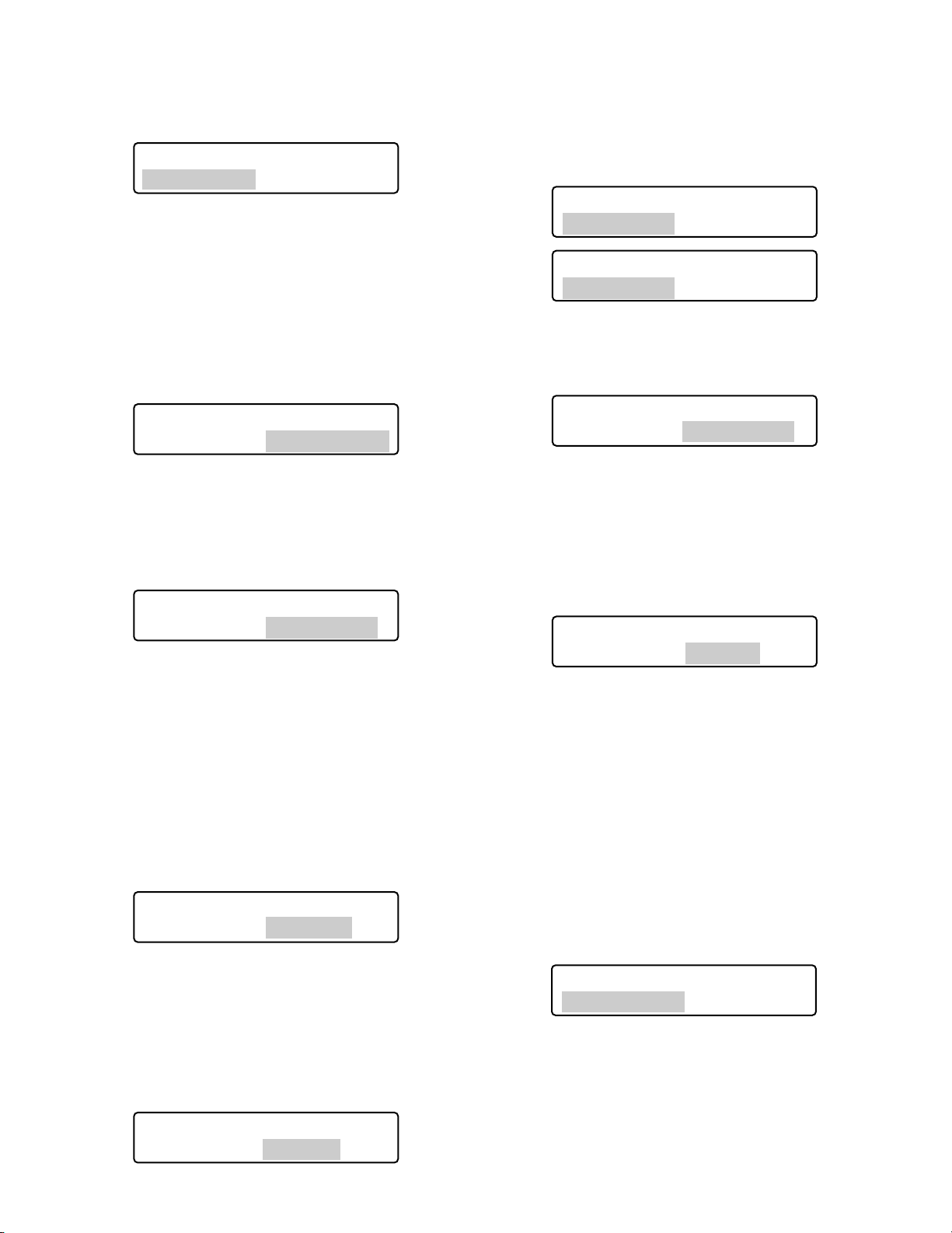
72
To deactivate auto login or auto logout
1. Select a system controller to deactivate auto login or
auto logout by performing either of the following.
• Rotate the JogDial clockwise or counterclockwise.
• Press the + or – button.
2. Press the CLEAR button.
“Clear OK?” will appear on the LCD.
Note: To cancel deactivating auto login, press the EXIT
or MON (ESC) button.
3. Press the ENTER or CAM (SET) button.
Auto login or auto logout will be deactivated.
“Erased” will appear on the LCD for a few seconds, and
the LCD display will return to Step 1.
● Operator Registration or Change
You can register new operators or change the parameter
settings. Up to 16 operators are registrable in the system.
Notes:
• Refer to p. 38 Operation Start (Login) for the factory
default.
• To return to the previous step, press the EXIT or MON
(ESC) button.
1. Display “Operator Setup” sub menu. (Refer to Step 1 to
4 of p. 61 To Recall Menu Functions.)
2. Select an operator to register or change the settings by
performing either of the following.
• Rotate the JogDial clockwise or counterclockwise.
• Press the + or – button.
2. Select a system controller to activate auto login or auto
logout by performing either of the following.
• Rotate the JogDial clockwise or counterclockwise.
• Press the + or – button.
Note: The factory default is “Cont No. 1”.
3. Rotate the shuttle ring clockwise or move the 3D joystick to the right.
4. To activate auto login, select an operator
(Operator 1 to 16) by performing the following.
• Rotate the JogDial clockwise or counterclockwise.
• Press the + or – button.
To activate auto logout, select the duration until auto
logout (Logout 5 to 120)* by performing the following.
* The numbers mean minutes.
• Rotate the JogDial clockwise or counterclockwise.
• Press the + or – button.
Notes:
• Parameters can be changed as follows.
Operator 1 → Operator 2 …→ Operator 16 → Logout
5 → Logout 10 …→ Logout 120 → Operator 1 …
•
To return the cursor to Cont No. n, rotate the shuttle ring
counterclockwise or move the 3D joystick to the left.
• Auto Logout setting will be activated after you log
into the system again.
5. Press the ENTER or CAM (SET) button.
“Set OK?” will appear on the LCD.
Note: To cancel the setting, press the EXIT or MON
(ESC) button.
6. Press the ENTER or CAM (SET) button again.
Auto login will be set.
"Memory” will appear on the LCD for a few seconds,
and the LCD display will return to Step 1.
Auto Login/out 403
Cont No.6 Off
Auto Login/out 403
Cont No.6 Operator06
Auto Login/out 403
Cont No.6 Operator06
Auto Login/out 403
Cont No.6 Logout 30
Auto Login/out 403
Cont No.6 Logout 30
Auto Login/out 403
Cont No.6 Clear OK?
Auto Login/out 403
Cont No.6 Erased
Auto Login/out 403
Cont No.6 Set OK?
Auto Login/out 403
Cont No.6 Memory
Operator Setup 404
Operator01
Page 73
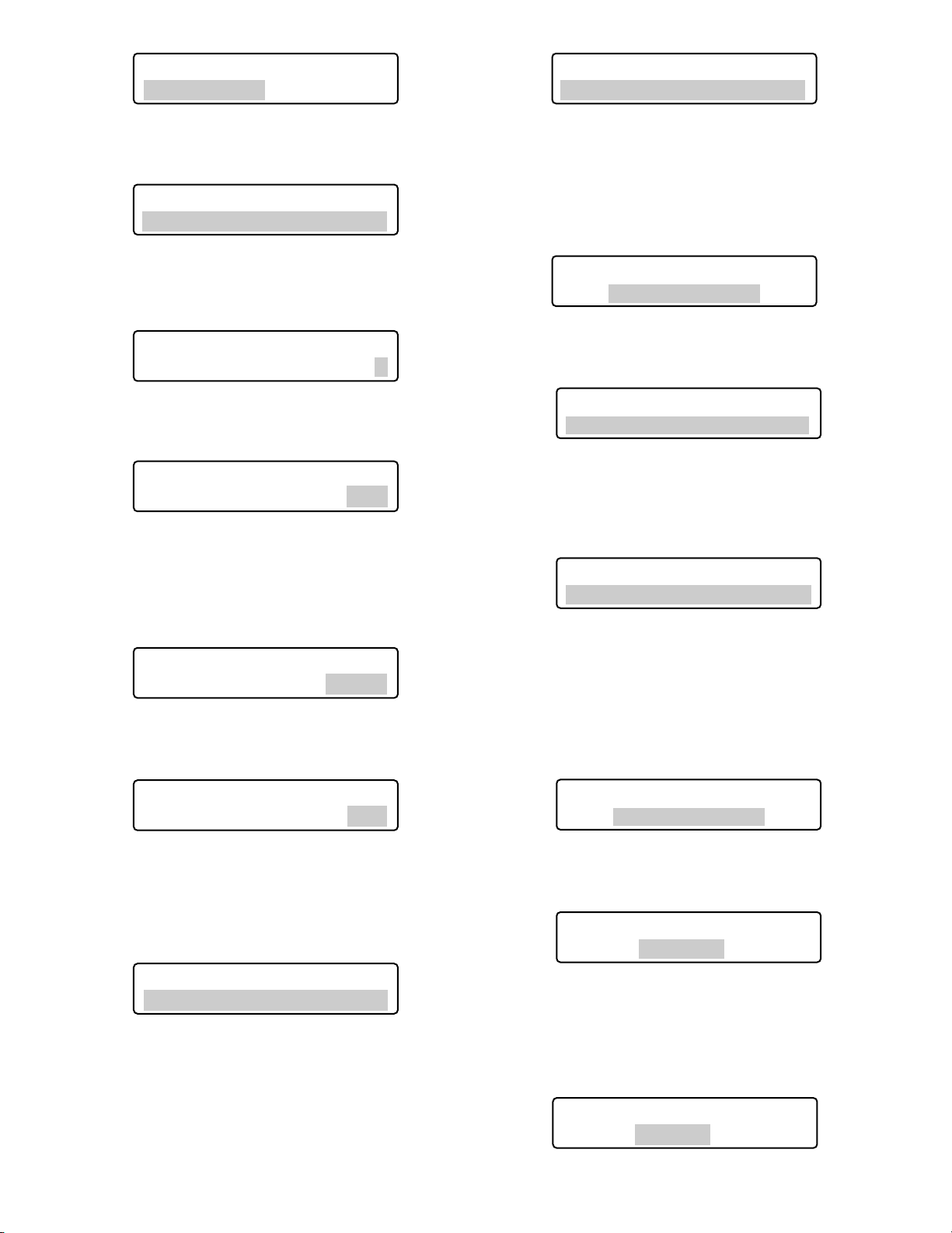
73
Note: When registering a new operator, select an oper-
ator number beside which “No Assign” is displayed.
3. Press the ENTER or CAM (SET) button.
“User ID” setting menu will appear on the LCD.
4. Enter a user ID by pressing the numeric buttons.
“1” to “99999” are available for the user ID number.
Note: If you have entered a wrong user ID, press the
CLEAR button.
5. Press the ENTER or CAM (SET) button.
The password entry form will appear on the LCD.
6. Enter a password by pressing the numeric buttons.
“1” to “99999” are available for the password.
Note: If you have entered a wrong password, press the
CLEAR button.
7. Press the ENTER or CAM (SET) button.
“Function Level” setting menu will appear on the LCD.
8. Set the function level by performing either of the follow-
ing.
• Rotate the JogDial clockwise or counterclockwise.
• Press the + or – button.
Notes:
• Refer to p. 74 Function Level Setting for details on
function level.
• You cannot change the function level of Operator 1.
If you try to change, “Level 1 Fixed” will appear on
the LCD.
9. Press the ENTER or CAM (SET) button.
“Camera Level” setting menu will appear on the LCD.
10. Set the camera level by performing either of the following.
• Rotate the JogDial clockwise or counterclockwise.
• Press the + or – button.
Notes:
• Refer to p. 75 Camera Level Setting for details on
camera level.
• You cannot change the camera level of Operator 1.
If you try to change, “Level 1 Fixed” will appear on
the LCD.
11. Press the ENTER or CAM (SET) button.
“Set OK?” will appear on the LCD.
12. Press the ENTER or CAM (SET) button again.
The new operator and the settings will be registered.
“Memory” will appear on the LCD for a few seconds,
and the LCD display will return to Step 1.
Operator Setup 404
Operator02
Operator07 404
Function Level = 2
Operator Setup 404
Operator07 No Assign
Operator07 404
User ID= 1
Operator07 404
User ID= 777
Operator01 404
Level1 Fixed
Operator07 404
Camera Level = 1
Operator07 404
Camera Level = 2
Operator07 404
Password= 12345
Operator07 404
Password= 333
Operator07 404
Function Level = 1
Operator01 404
Level1 Fixed
Operator07 404
Set OK?
Operator07 404
Memory
Page 74
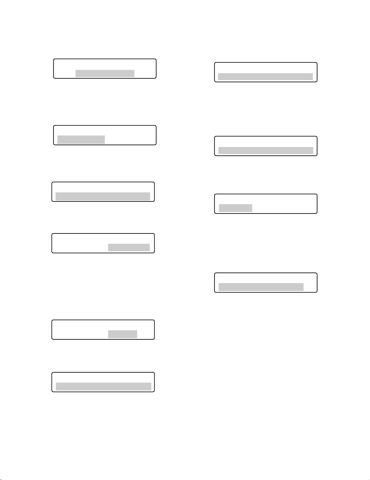
74
To delete an operator
Note: You cannot delete Operator 1. If you try to delete,
“Level1 Fixed” will appear on the LCD.
1. Select an operator to delete by performing either of the
following.
• Rotate the JogDial clockwise or counterclockwise.
• Press the + or – button.
Note: If you select an operator not registered, “No
Assign” will appear beside the operator number.
2. Press the CLEAR button.
“Clear OK?” will appear on the LCD.
Note: To cancel deleting the operator, press the EXIT
or MON (ESC) button.
3. Press the ENTER or CAM (SET) button.
• The operator will be deleted.
•“Erased” will appear on the LCD for a few seconds,
and the LCD display will return to Step 1.
Note: After the operator has been deleted, “No Assign”
will appear beside the operator number.
● Function Level Setting
You can change the function levels for each button (except
for numeric buttons) of main unit and 3D joystick unit. The
function levels range between Table No. 1 (highest level)
and 3 (Lowest level).
Note: Table No. 1 is fixed to E (Enabled) for all the func-
tions.
1. Display “Function Level” sub menu. (Refer to Step 1 to
4 of p. 61 To Recall Menu Functions.)
2. Select a desired table (= function level) by performing
either of the following.
• Rotate the JogDial clockwise or counterclockwise.
• Press the + or – button.
• Enter the table number with the numeric buttons.
3. Press the CAM (SET) button.
The setting menu for the selected table will appear on
the LCD.
4. Select a desired function by performing one of the following.
• Rotate the JogDial clockwise or counterclockwise.
• Press the + or – button.
• Enter the function number with the numeric buttons.
The function setting will appear on the LCD.
The following diagram describes the function settings
changeable and their factory defaults.
Operator01 404
Level1 Fixed
Operator Setup 404
Operator07
Operator Setup 404
Operator15 No Assign
Operator Setup 404
Operator07 Clear OK?
Function Level 405
Table No. =1
Function Level 405
Table No. =2
Function Table2 405
01 MENU =E
Function Table2 405
08 IRIS OPEN/CLOSE=E
Operator Setup 404
Operator07 Erased
Operator Setup 404
Operator07 No Assign
Page 75
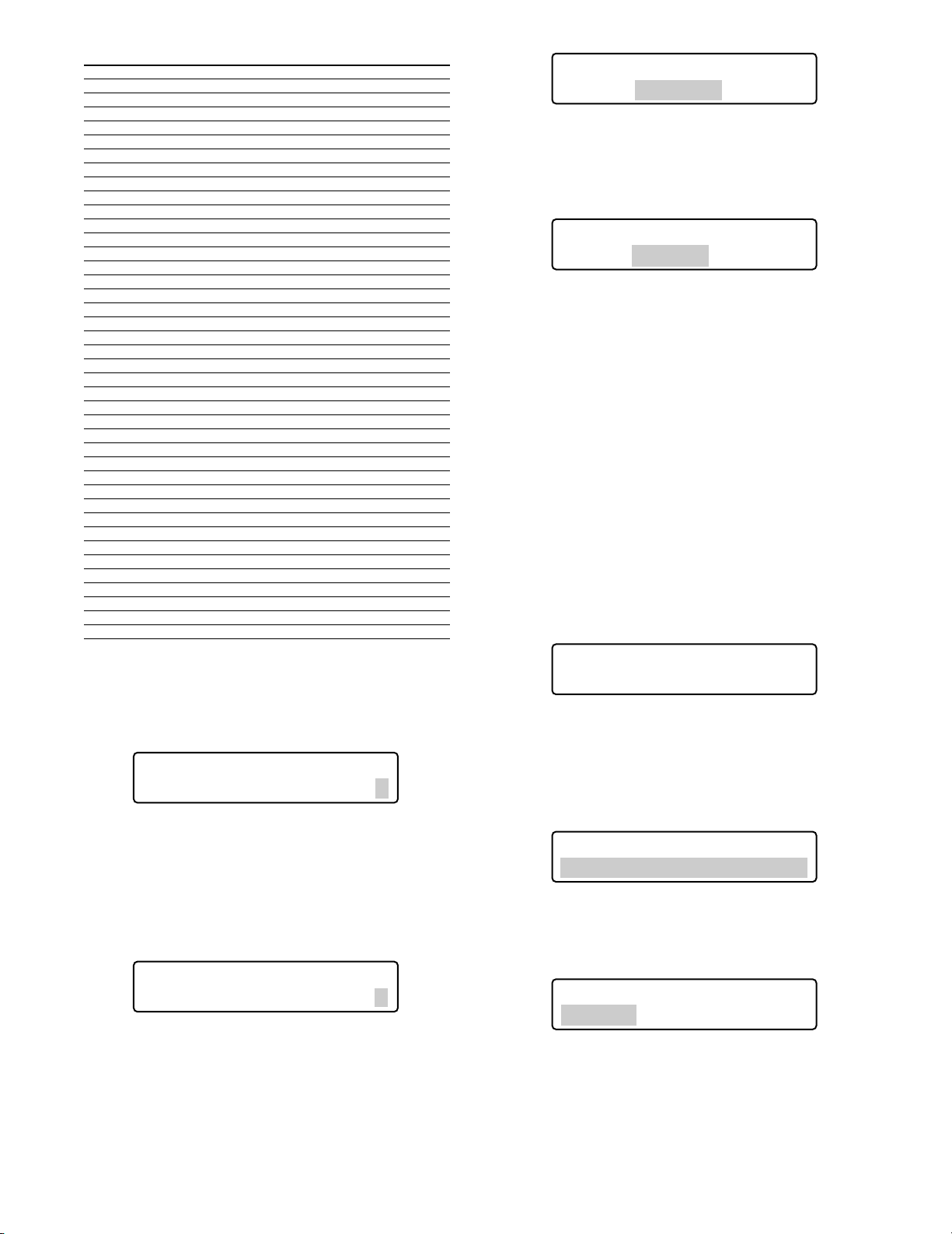
75
Function Table 2 Table 3
01 MENU D D
02 F1 – F4 E E
03 F5 – F8 E E
04 A B E E
05 TOP SW E E
06 JOYSTICK E E
07 FOCUS NEAR/FAR
EE
08 IRIS OPEN/CLOSE
ED
09 CAM/SET E E
10 MON/ESC E E
11 UNIT E E
12 RECORDER E E
13 CAM POSI E E
14 PRESET E E
15 PGM PRESET D D
16 HISTORY E E
17 –/+ E E
18 JOG DIAL E E
19 SHUTTLE RING
EE
20 SHUTTLE HOLD
EE
21 PLAY/PAUSE E E
22 STOP E E
23 REC E D
24 ALM SUSPEND
ED
25 ALM RESET E E
26 OSD E E
27 ALM RECALL E E
28 SEQ PAUSE E E
29 SEQUENCE E E
30 MULTI SCREEN
EE
31 EL-ZOOM E E
32 AUX1 ON/OFF E E
33 AUX2 ON/OFF E E
34 DEF ON/OFF E E
35 WIPER ON E E
36 SYS FUNC D D
37 CAM FUNC D D
38 GO TO LAST E E
39 MARK E E
40 SEARCH E E
41 T&D SEARCH E E
E=Enabled, D=Disabled
5. Rotate the shuttle ring clockwise or move the 3D joy-
stick to the right. The cursor will jump to the next item.
Note: To return to Step 4, rotate the shuttle ring coun-
terclockwise or move the 3D joystick to the left.
6. Select E or D by performing either of the following.
• Rotate the JogDial clockwise or counterclockwise.
• Press the + or – button.
Note: To change the settings of other functions, repeat
Step 4 to 6.
7. Press the ENTER or CAM (SET) button.
“Set OK?” will appear on the LCD.
Note: To cancel the setting, press the EXIT or MON
(ESC) button. The LCD display will return to Step 6.
8. Press the ENTER or CAM (SET) button again.
The function levels will be set for the selected table.
“Memory” will appear on the LCD for a few seconds,
and the LCD display will return to Step 1.
● Camera Level Setting
You can change the camera levels for each operator. The
camera levels range between Table No. 1 (highest level)
and 3 (Lowest level).
Notes:
• Table No. 1 is fixed to E (Enabled) for all cameras.
• As the factory default, Table No. 2 and 3 are set to E for
all cameras.
1. Display “Camera Level” sub menu. (Refer to Step 1 to 4
of p. 61 To Recall Menu Functions.)
2. Select a desired table (= camera level) by performing
one of the following.
• Rotate the JogDial clockwise or counterclockwise.
• Press the + or – button.
• Enter the function number with the numeric buttons.
3. Press the CAM (SET) button.
The setting menu for the selected table will appear on
the LCD.
4. Select a desired camera channel by performing one of
the following.
• Rotate the JogDial clockwise or counterclockwise.
• Press the + or – button.
• Enter the camera number with the numeric buttons.
Function Table2 405
Set OK?
Function Table2 405
Memory
Function Table2 405
08 IRIS OPEN/CLOSE=E
Function Table2 405
08 IRIS OPEN/CLOSE=D
Camera Level 406
Table No. =1
Camera Level 406
Table No. =3
Camera Table3 406
Cam001 =E
Page 76
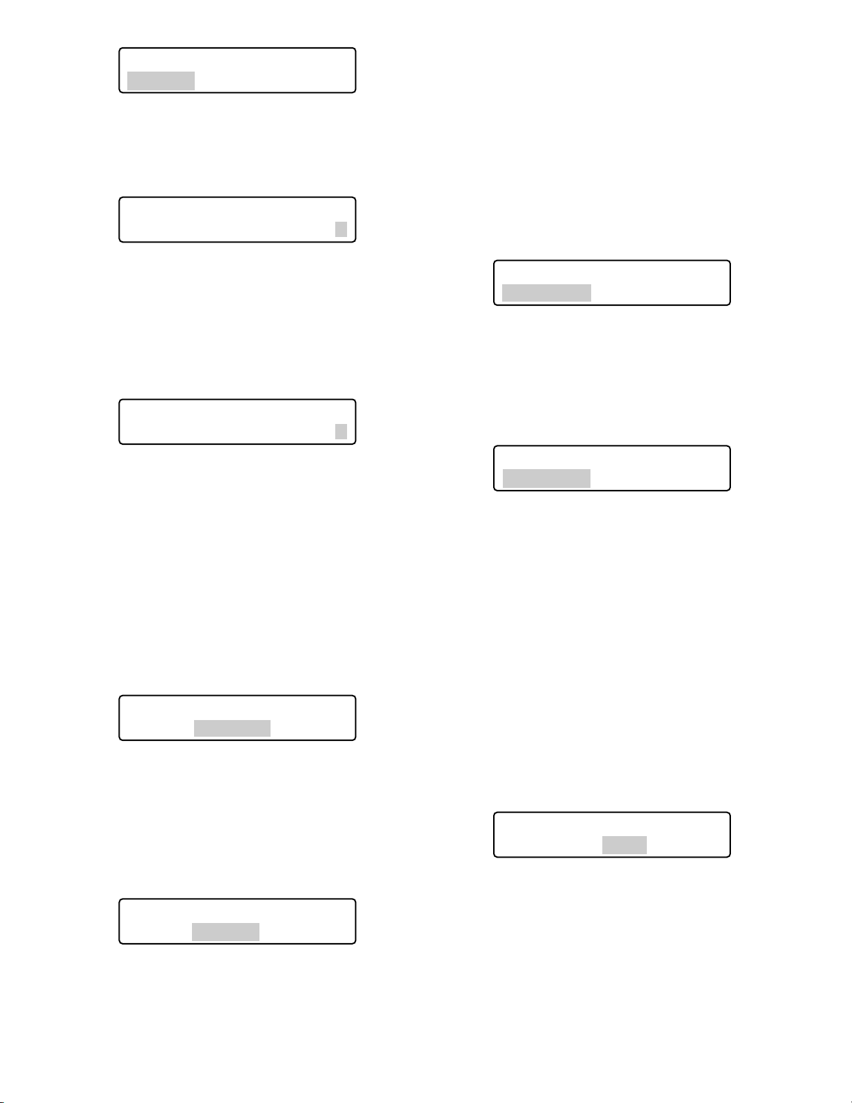
76
Note: You can select a camera channel from 1 to 999.
5. Rotate the shuttle ring clockwise or move the 3D joystick to the right. The cursor will jump to the next item.
Note: To return to Step 4, rotate the shuttle ring coun-
terclockwise or move the 3D joystick to the left.
6. Select E (= Enabled) or D (= Disabled) by performing
either of the following.
• Rotate the JogDial clockwise or counterclockwise.
• Press the + or – button.
E (= Enabled): The operator can display the camera image on the monitor and control panning/tilting. (VIEW & CONTROL)
D (= Disabled): The operator can display the camera image on the monitor, but cannot control the
panning/tilting. (VIEW ONLY)
Note: To change the settings of other cameras, repeat
Step 4 to 6.
7. Press the ENTER or CAM (SET) button.
“Set OK?” will appear on the LCD.
Note: To cancel the setting, press the EXIT or MON
(ESC) button. The LCD display will return to Step 6.
8. Press the ENTER or CAM (SET) button again.
The camera levels will be set for the selected table.
“Memory” will appear on the LCD for a few seconds,
and the LCD display will return to Step 1.
● Camera Position Registration or
Clearing
This system controller can memorize camera position numbers, which are the combination of camera numbers and
preset position numbers. By entering a camera position
number, you can select a desired camera and preset position at a time. You can register up to 1 000 camera position
numbers.
1. Display “Cam Posi Map” sub menu. (Refer to Step 1 to
4 of p. 61 To Recall Menu Functions.)
2. Select a camera position number to register by performing one of the following.
• Rotate the JogDial clockwise or counterclockwise.
• Press the + or – button.
• Enter the camera position number with the numeric
buttons.
Notes:
• To register a new position number, press the
numeric buttons.
• You can select a camera position number from 0 to
999.
3. Rotate the shuttle ring clockwise or move the 3D joystick to the right. The cursor will jump to the next item.
Note: To return to Step 2, rotate the shuttle ring coun-
terclockwise or move the 3D joystick to the left.
4. Select a desired camera channel by performing one of
the following.
• Rotate the JogDial clockwise or counterclockwise.
• Press the + or – button.
• Enter the camera number with the numeric buttons.
Note: You can select a camera channel from 1 to 999.
5. Rotate the shuttle ring clockwise or move the 3D joystick to the right. The cursor will jump to the next item.
Note: To return to Step 4, rotate the shuttle ring coun-
terclockwise or move the 3D joystick to the left.
Camera Table3 406
Cam064 =E
Camera Table3 406
Cam064 =E
Camera Table3 406
Cam064 =D
Cam Posi Map 407
Cam-P001 C001 Pre001
Cam Posi Map 407
Cam-P016 C001 Pre016
Camera Table3 406
Set OK?
Camera Table3 406
Memory
Cam Posi Map 407
Cam-P016 C005 Pre016
Page 77
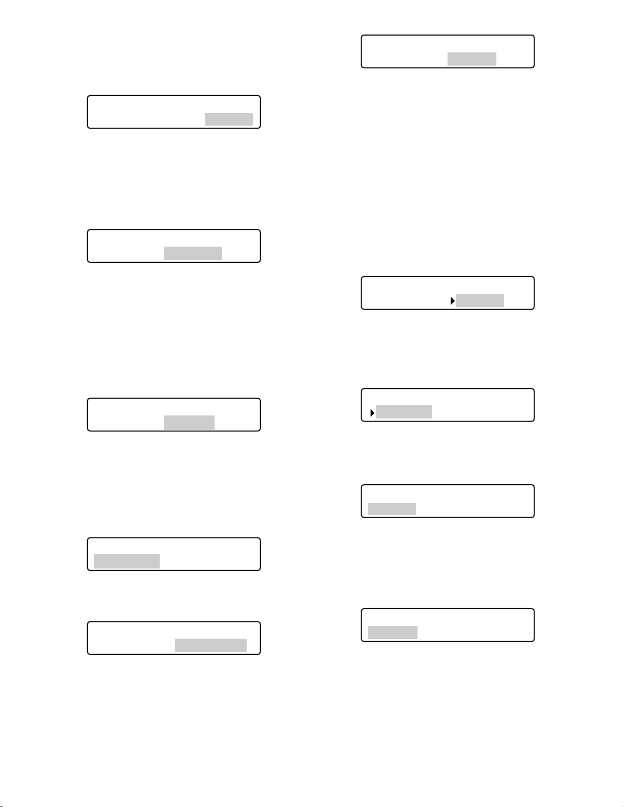
77
6. Select a desired preset position number by performing
either of the following.
• Rotate the JogDial clockwise or counterclockwise.
• Press the + or – button.
Note: You can select a preset position number from 1
to 256.
7. Press the ENTER or CAM (SET) button.
“Set OK?” will appear on the LCD.
Note: To cancel the setting, press the EXIT or MON
(ESC) button. The LCD display will return to Step 6.
8. Press the ENTER or CAM (SET) button again.
The specified camera channel and preset position number will be set for the selected camera position.
“Memory” will appear on the LCD for a few seconds,
and the LCD display will return to Step 1.
To delete a camera position
1. Select a camera position to delete by performing either
of the following.
• Rotate the JogDial clockwise or counterclockwise.
• Press the + or – button.
2. Press the CLEAR button.
“Clear OK?” will appear on the LCD.
Note: To cancel deleting the camera position, press the
EXIT or MON (ESC) button.
3. Press the ENTER or CAM (SET) button.
The camera position will be deleted.
“Erased” will appear on the LCD for a few seconds, and
the LCD display will return to Step 1.
● Associating Camera Numbers with
Unit Numbers
You can register camera-unit maps (the association of camera numbers and unit numbers). Up to 999 camera unit
maps can be registered. You can select a camera by entering the camera channel alone, even if the camera is connected to system unit not currently selected.
Note: If “Enable” is selected in Step 2, you can select only
camera numbers associated with unit numbers.
1. Display “Cam-Unit Map” sub menu. (Refer to Step 1 to
4 of p. 61 To Recall Menu Functions.)
Note: To disable camera-unit maps, display the “s”
mark beside “Disable” by rotating the shuttle ring
counterclockwise or moving the 3D joystick to the
left.
2. Press the ENTER or CAM (SET) button.
The camera-unit setting will appear on the LCD.
3. Select a desired camera channel by performing one of
the following.
• Rotate the JogDial clockwise or counterclockwise.
• Press the + or – button.
• Enter the camera number with the numeric buttons.
Notes:
• To register a new position number, press the
numeric buttons.
• You can select a camera channel from 1 to 999.
• The following are the factory default settings.
Cam Posi Map 407
Cam-P016 Erased
Cam Posi Map 407
Cam-P016 C005 Pre032
Cam Posi Map 407
Cam-P016 Set OK?
Cam-Unit Map 408
Disable Enable
Cam Posi Map 407
Cam-P016 Memory
Cam Posi Map 407
Cam-P016 C005 Pre032
Cam Posi Map 407
Cam-P016 Clear OK?
Cam-Unit Map 408
Disable Enable
Cam-Unit Map 408
Cam001 Unit01
Cam-Unit Map 408
Cam016 Unit01
Page 78
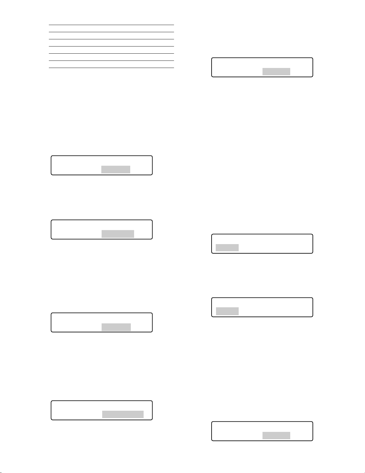
78
Default settings of camera-unit maps
Cam Unit
001 to 016 01
017 to 032 02
033 to 048 03
049 to 064 04
065 to 256 – –
4. Rotate the shuttle ring clockwise or move the 3D joystick to the right. The cursor will jump to the next item.
Note: To return to Step 3, rotate the shuttle ring coun-
terclockwise or move the 3D joystick to the left.
5. Select a desired unit number by performing either of the
following.
• Rotate the JogDial clockwise or counterclockwise.
• Press the + or – button.
Note: You can select a unit number from 1 to 99.
6. Press the ENTER or CAM (SET) button.
“Set OK?” will appear on the LCD.
Note: To cancel the setting, press the EXIT or MON
(ESC) button. The LCD display will return to Step 6.
7. Press the ENTER or CAM (SET) button again.
The specified camera channel and unit number will be
set for the selected camera-unit map.
“Memory” will appear on the LCD for a few seconds,
and the LCD display will return to Step 1.
To delete a camera-unit map
1. Perform Step 1 to 3 in p. 77 Associating Camera
Numbers with Unit Numbers.
2. Press the CLEAR button.
“Clear OK?” will appear on the LCD.
Note: To cancel deleting the setting, press the EXIT or
MON (ESC) button.
3. Press the ENTER or CAM (SET) button.
The camera-unit map will be deleted.
“Erased” will appear on the LCD for a few seconds, and
the LCD display will return to Step 3.
Note: After all the camera-unit maps have been delet-
ed, “Cam000” will appear for the camera channel
area.
● Associating Recorder Numbers with
Unit Numbers
You can register HDD-unit maps (the association settings of
recorder numbers and unit numbers). Up to 16 HDD-unit
maps can be registered. You can select a recorder by
entering a desired recorder number.
Note: As the factory default, recorder numbers have been
associated with unit numbers having the same numbers. (“HDD01” with “Unit01”, “HDD02” with “Unit02”...)
1. Display “HDD-Unit Map” sub menu. (Refer to Step 1 to
4 of p. 61 To Recall Menu Functions.)
2. Select a desired recorder number by performing either
of the following.
• Rotate the JogDial clockwise or counterclockwise.
• Press the + or – button.
Note: You can select a recorder number from 1 to 16.
3 .Rotate the shuttle ring clockwise or move the 3D joy-
stick to the right. The cursor will jump to the next item.
Note: To return to Step 2, rotate the shuttle ring coun-
terclockwise or move the 3D joystick to the left.
4. Select a desired unit number by performing either of the
following.
• Rotate the JogDial clockwise or counterclockwise.
• Press the + or – button.
Cam-Unit Map 408
Cam016 Unit02
Cam-Unit Map 408
Cam016 Erased
Cam-Unit Map 408
Cam016 Set OK?
Cam-Unit Map 408
Cam016 Memory
Cam-Unit Map 408
Cam016 Clear OK?
HDD-Unit Map 409
HDD01 Unit01
HDD-Unit Map 409
HDD06 Unit06
HDD-Unit Map 409
HDD06 Unit05
Page 79
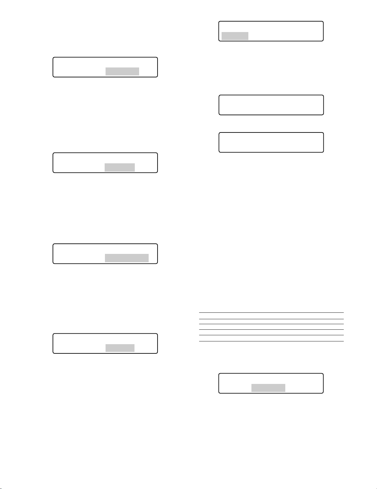
79
Note: You can select a unit number from 1 to 99.
5. Press the ENTER or CAM (SET) button.
“Set OK?” will appear on the LCD.
Note: To cancel the setting, press the EXIT or MON
(ESC) button. The LCD display will return to Step 4.
6. Press the ENTER or CAM (SET) button again.
The specified recorder number and unit number will be
set for the selected HDD-unit map.
“Memory” will appear on the LCD for a few seconds,
and the LCD display will return to Step 1.
To delete a HDD-unit map
1. Perform Step 1 and 2 in p. 78 Associating Recorder
Numbers with Unit Numbers.
2. Press the CLEAR button.
“Clear OK?” will appear on the LCD.
Note: To cancel deleting the setting, press the EXIT or
MON (ESC) button.
3. Press the ENTER or CAM (SET) button.
The HDD-unit map will be deleted.
“Erased” will appear on the LCD for a few seconds, and
the LCD display will return to Step 1.
Note: After all the HDD-unit maps have been deleted,
“HDD00” will appear for the camera channel area.
“HDD-Unit Map Check” menu will appear on the
LCD.
● LCD Title Editing
You can edit button function titles displayed on the LCD.
If you set LCD titles related to the registered button functions, controllability will be improved.
1 .Display “LCD Title” sub menu. (Refer to Step 1 to 4 of
p. 61 To Recall Menu Functions.)
2. Select a desired title group (F1-F4 or F5-F8) by rotating
the shuttle ring or moving the 3D joystick.
3. Press the ENTER or CAM (SET) button.
The title editing form will appear on the LCD.
4. Select desired characters by performing either of the
following.
• Rotate the JogDial clockwise or counterclockwise.
• Press the + or – button.
Notes:
• To move the cursor, rotate the shuttle ring (clockwise or counterclockwise) or move the 3D joystick
(to the right or left)
• To delete a character, press the CLEAR button.
• To display the next or previous character group,
rotate the JogDial while holding down the SHIFT
button.(For example, when the cursor is pointed on
“C”, “a” can be displayed by rotating the JogDial
clockwise while holding down the SHIFT button.)
• The following diagram describes the available characters.
Character group Characters
Space “”(Space) ■
Capital letters ABCDEFGHIJKLMNOPQRSTUVWXYZ
Small letters abcdefghijklmnopqrstuvwxyz
Numerics 0123456789
Symbols !”#$%&’()∗+,–./:;<=>?[¥]^_{|}→←@
5. Press the ENTER or CAM (SET) button.
“Set OK?” will appear on the LCD.
Note: To cancel the setting, press the EXIT or MON
(ESC) button. The LCD display will return to Step 4.
6. Press the ENTER or CAM (SET) button again.
The LCD title you have edited will be registered.
“Memory” will appear on the LCD for a few seconds,
and the LCD display will return to Step 1.
HDD-Unit Map 409
HDD06 Set OK?
LCD Title 410
F1-F4 F5-F8
LCD Title F1-F4 410
F1 F2 F3 F4
When "F1 — F4" is selected
LCD Title F5-F8 410
F5 F6 F7 F8
HDD-Unit Map 409
HDD06 Memory
HDD-Unit Map 409
HDD06 Clear OK?
HDD-Unit Map 409
HDD06 Erased
When "F5 — F8" is selected
LCD Title F1-F4 410
Set OK?
Page 80
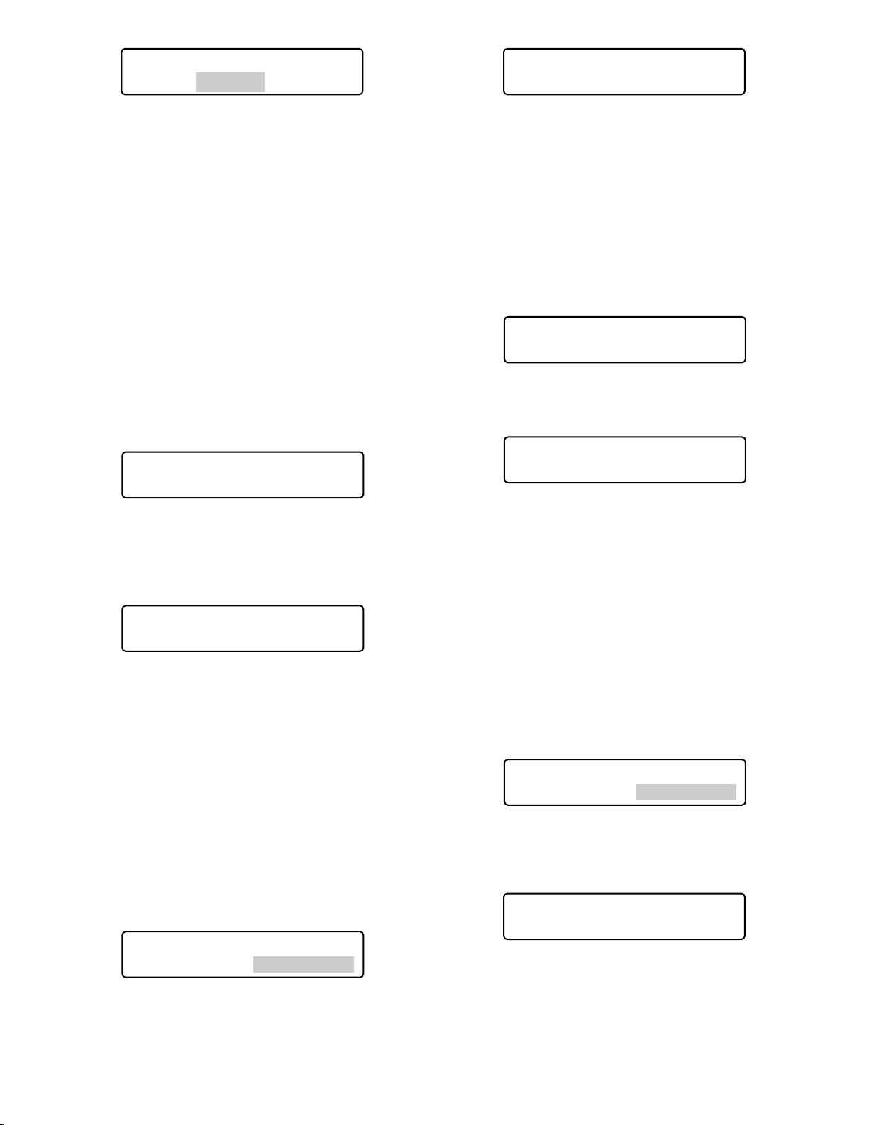
80
■ Joystick Button Functions
If you register a joystick button function to a function button
or joystick function button, you can activate the associated
function only with pressing the button.
● Camera Function
You can recall camera functions by entering function numbers from this system controller.
Note: Refer to the operating instruction of camera for
details on camera function.
1. Display “Camera Function” sub menu. (Refer to Step 1
to 4 of p. 61 To Recall Menu Functions.)
2 Enter a camera function number by pressing the
numeric buttons. The entered number will appear on
the LCD.
Notes:
• To cancel the numeric entry, press the CLEAR button.
• If you press the CAM (SET) button, the image of
selected camera will be displayed on the active
monitor, and the LCD will return to the default status.
3. Press the F1 button.
• The associated camera function will be activated.
• The specified camera function will blink on the LCD
for a few seconds, and the LCD display will return
to Step 1.
Note: When the camera function has been activated by
the A button, the LCD display will become as follows.
● System Function
You can recall system functions by entering function numbers from this system controller.
Note: Refer to the operating instruction of system unit for
details on system function.
1. Display “Camera Function” sub menu. (Refer to Step 1
to 4 of p. 61 To Recall Menu Functions.)
2. Enter a system function number by pressing the numeric buttons. The entered number will appear on the LCD.
Notes:
• To cancel the numeric entry, press the CLEAR button.
• If you press the CAM (SET) button, the image of
selected camera will be displayed on the active
monitor, and the LCD will return to the default status.
3. Press the F1 button.
• The associated system function will be activated.
• The specified system function will blink on the LCD
for a few seconds, and the LCD display will return
to Step 1.
Note: When the system function has been activated by
the A button, the LCD display will become as follows.
LCD Title F1-F4 410
Memory
Camera Function A
Code=0007
Camera Function 501
"Input Code Number"
Camera Function____7
"Enter F1 Button"
System Function 502
"Input Code Number"
System Function____5
"Enter F1 Button"
System Function 502
Code=___5
Camera Function 501
Code=___7
System Function A
Code=0018
Page 81
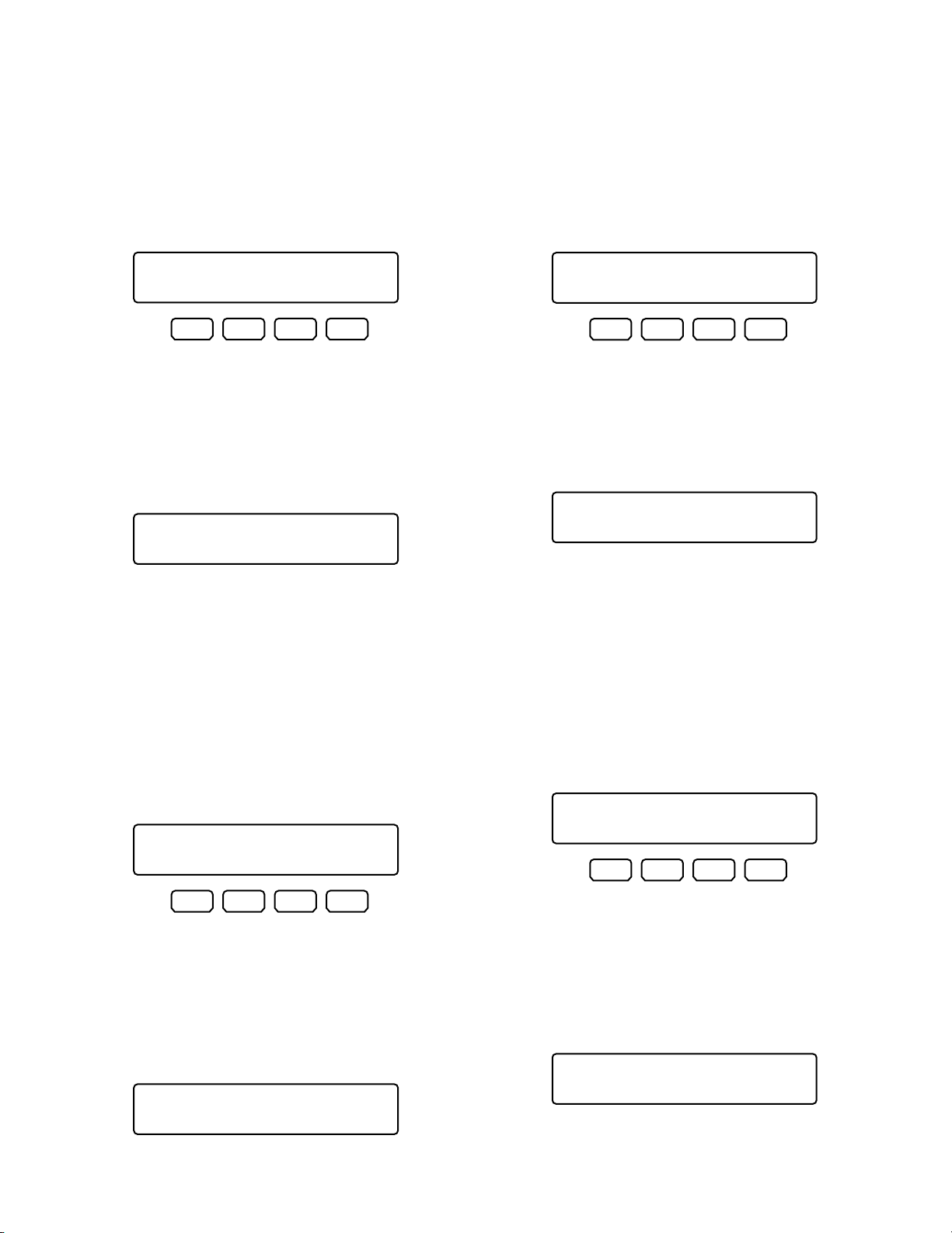
81
● Auto Pan
You can activate the auto pan mode for the selected camera.
Note: Refer to the operating instruction of camera for
details of this function.
1. Display “Auto Pan” sub menu. (Refer to Step 1 to 4 of p.
61 To Recall Menu Functions.)
2. Press the F1 button.
The auto pan mode will be activated.
Note: When the auto pan function has been activated
with the A button, the LCD display will become as
follows.
● Camera Sequence
You can activate the camera sequence mode for the selected camera.
Note: Refer to the operating instruction of camera for
details of this function.
1. Display “Camera Sequence” sub menu. (Refer to Step
1 to 4 of p. 61 To Recall Menu Functions.)
2. Press the F1 button.
The camera sequence mode will be activated.
Note: When the camera sequence mode has been acti-
vated with the A button, the LCD display will
become as follows.
● Camera Sort
You can activate the auto sort mode for the selected camera.
Note: Refer to the operating instruction of camera for
details of this function.
1. Display “Camera Sort” sub menu. (Refer to Step 1 to 4
of p. 61 To Recall Menu Functions.)
2. Press the F1 button.
The camera sort mode will be activated.
Note: When the camera sort mode has been activated
with the A button, the LCD display will become as
follows.
● Patrol Play
You can activate the patrol play function for the selected
camera.
Note: Refer to the operating instruction of camera for
details of this function.
1. Display “Patrol Play” sub menu. (Refer to Step 1 to 4 of
p. 61 To Recall Menu Functions.)
2. Press the F1 button.
The patrol play mode will be activated.
Note: When the patrol play mode has been activated
with the A button, the LCD display will become as
follows.
Auto Pan 503
“Enter F1 Button”
F1 F2 F3 F4
Auto Pan A
Camera Sort 505
“Enter F1 Button”
F1 F2 F3 F4
Camera Sort A
Camera Sequence 504
“Enter F1 Button”
F1 F2 F3 F4
Patrol Play 506
“Enter F1 Button”
F1 F2 F3 F4
Patrol Play A
Camera Sequence A
Page 82
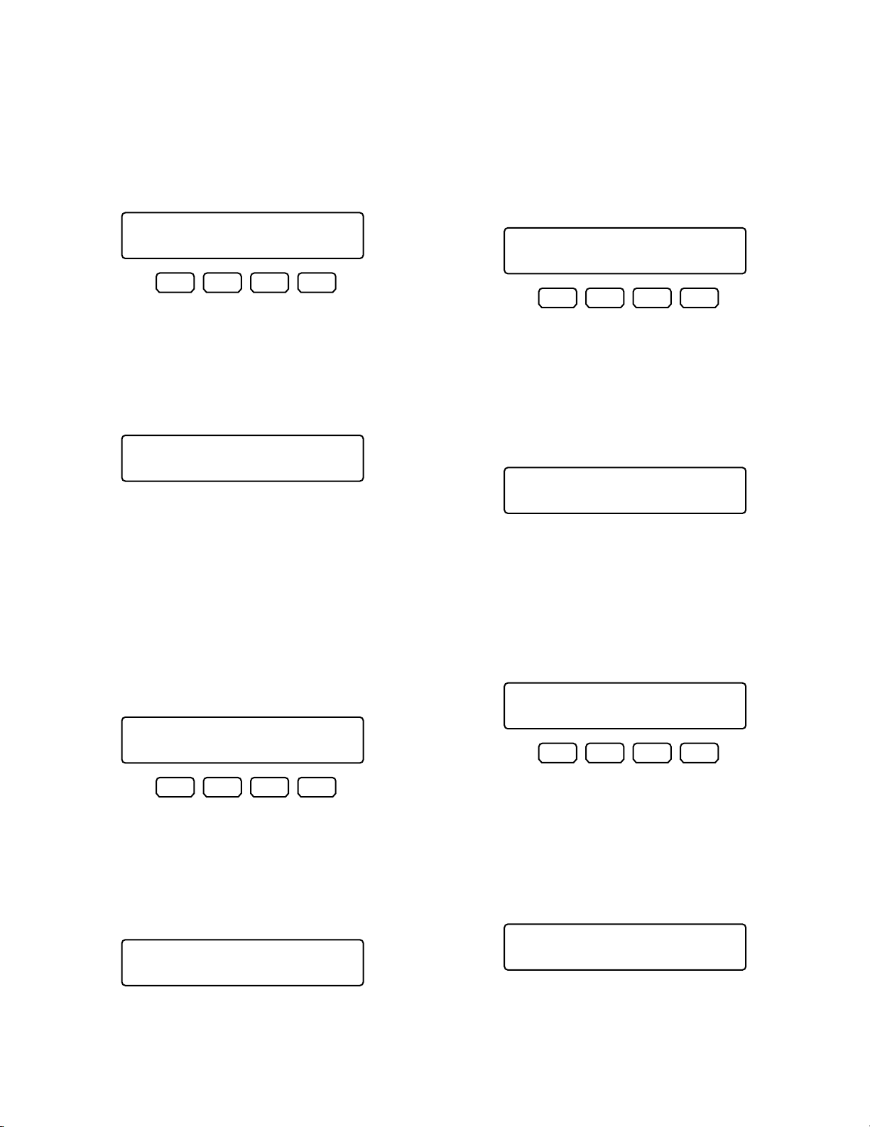
82
● Iris Reset
You can activate the iris reset function for the selected
camera.
Note: Refer to the operating instruction of camera for
details of this function.
1. Display “Iris Reset” sub menu. (Refer to Step 1 to 4 of
p. 61 To Recall Menu Functions.)
2. Press the F1 button.
The iris reset function will be activated.
Note: When the iris reset function has been activated
with the A button, the LCD display will become as
follows.
● Camera +1
You can change the camera image on the monitor to the
higher channel.
1. Display “Camera +1” sub menu. (Refer to Step 1 to 4 of
p. 61 To Recall Menu Functions.)
2. Press the F1 button.
The image of higher camera channel will be displayed
on the active monitor.
Note: When the Camera +1 function has been activat-
ed with the A button, the LCD display will become
as follows
● Home Position
You can move the selected camera to the home position.
Note: Refer to the operating instruction of camera for
details of this function.
1 Display “Home Position” sub menu. (Refer to Step 1 to
4 of p. 61 To Recall Menu Functions.)
2. Press the F1 button.
The camera will move to the home position.
Note: When the home position has been activated with
the A button, the LCD display will become as follows.
● Auto Focus
You can activate the auto focus function for the selected
camera.
Note: Refer to the operating instruction of camera for
details of this function.
1. Display “Auto Focus” sub menu. (Refer to Step 1 to 4 of
p. 61 To Recall Menu Functions.)
2. Press the F1 button.
The auto focus function will be activated.
Note: When the auto focus function has been activated
with the A button, the LCD display will become as
follows.
Home Position 507
“Enter F1 Button”
F1 F2 F3 F4
Home Position A
Iris Reset 509
“Enter F1 Button”
F1 F2 F3 F4
Iris Reset A
Auto Focus 508
“Enter F1 Button”
F1 F2 F3 F4
Auto Focus A
Camera +1 510
“Enter F1 Button”
F1 F2 F3 F4
Camera +1 A
Page 83
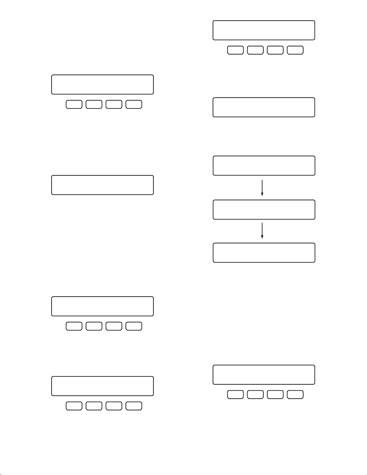
83
● Camera –1
You can change the camera image on the monitor to the
lower channel.
1. Display “Camera –1” sub menu. (Refer to Step 1 to 4 of
p. 61 To Recall Menu Functions.)
2. Press the F1 button.
The image of lower camera channel will be displayed
on the active monitor.
Note: When the Camera –1 function has been activated
with the A button, the LCD display will become as
follows.
● A - B Repeat Playback (WJ-HD300
Series Only)
The description is the same as that of button function. Refer
to p. 67 A – B Repeat Playback Setting.
Note: Refer to the operating instruction of recorder for
details of this function.
1. Display “HD300 A – B Repeat” sub menu. (Refer to
Step 1 to 4 of p. 61 To Recall Menu Functions.)
2. Press the F1 button at the point you wish to start playback.
The playback start point (A) will be set, and “Start” will
appear on the LCD for a few seconds.
3.
Press the F1 button again at the point you wish to end
playback. The playback end point (B) will be set, and
“End” will appear on the LCD for a few seconds. Then, the
repeat playback will be performed between (A) and (B).
Notes:
• To quit the repeat playback, press the F1 button
again. “Cancel” will appear on the LCD for a few
seconds.
• When the A – B repeat playback function has been
activated with the function button, the LCD display
will become as follows.
● Recorded-image Copy (WJ-HD500
Series Only)
You can copy recorded images from the built-in hard disk
to an external recording device.
Note: Refer to the operating instruction of recorder for
details of this function.
1. Display “HD500 Copy” sub menu. (Refer to Step 1 to 4
of p. 61 To Recall Menu Functions.)
2. Press the F1 button.
The record copy function will be activated.
Note: When the record copy function has been activat-
ed with the A button, the LCD display will become
as follows.
Camera -1 511
“Enter F1 Button”
F1 F2 F3 F4
Camera -1 A
HD300 A—B Repeat 512
End
F1 F2 F3 F4
HD300 A—B Repeat 512
Cancel
HD300 A—B Repeat A
Start
HD300 A—B Repeat 512
“Enter F1 Button”
F1 F2 F3 F4
HD300 A—B Repeat 512
Start
F1 F2 F3 F4
HD300 A—B Repeat A
End
HD300 A—B Repeat A
Cancel
HD500 Copy 513
“Enter F1 Button”
F1 F2 F3 F4
Page 84
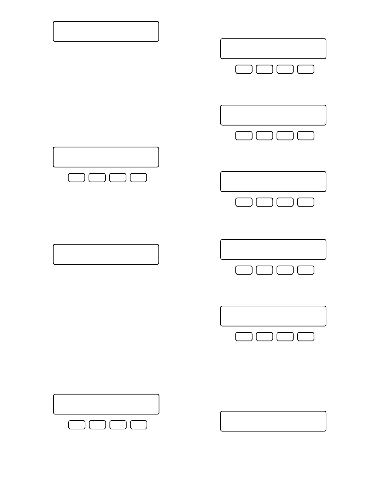
84
● Alarm Search (WJ-HD200 Series /
WJ-HD100 Series)
You can move the playback start point to the next alarm
record of recorded image data.
Note: Refer to the operating instruction of recorder for
details of this function.
1. Display “HD200 Alm Search” sub menu. (Refer to Step
1 to 4 of p. 61 To Recall Menu Functions.)
2. Press the F1 button.
The alarm search function will be activated.
Note: When the alarm search function has been activat-
ed with the A button, the LCD display will become
as follows.
● Multiscreen Display
You can change the multiscreen segment patterns of monitor connected to the selected system unit.
Note: Available multiscreen segment patterns differ
depending on system units. Refer to the operating
instructions of system units.
1. Display a desired sub menu among the following.
(Refer to Step 1 to 4 of p. 61 To Recall Menu
Functions.)
4-segment multiscreen display
7-segment multiscreen display
9-segment multiscreen display
10-segment multiscreen display
13-segment multiscreen display
16-segment multiscreen display
2. Press the F1 button.
The multiscreen display function will be activated.
Note: When the multiscreen display function has been
activated with the A button, the LCD display will
become as follows.
HD500 Copy A
Multi 7-Seg 516
“Enter F1 Button”
F1 F2 F3 F4
Multi 9-Seg 517
“Enter F1 Button”
F1 F2 F3 F4
HD200 Alm Search 514
“Enter F1 Button”
F1 F2 F3 F4
HD200 Alm Search A
Multi 10-Seg 518
“Enter F1 Button”
F1 F2 F3 F4
Multi 13-Seg 519
“Enter F1 Button”
F1 F2 F3 F4
Multi 16-Seg 520
“Enter F1 Button”
F1 F2 F3 F4
Multi 4-Seg 515
“Enter F1 Button”
F1 F2 F3 F4
Multi 4-Seg A
Page 85
85
TROUBLESHOOTING
Check the following before requesting repair.
If a trouble cannot be corrected even after checking and trying remedy, contact your dealer.
Refer to p. 36.
Problem Check item and Remedy Reference
The power of system controller is not
turned on.
The AC adapter may be disconnected
from either the system controller or the
AC outlet. Check the connection.
The DC plug may not be firmly plugged
into the DC 9 V Input jack of system
controller. Check the connection.
Refer to p. 36.
The brightness of LCD is not enough. /
Characters do not appear on the LCD.
The display setting value of LCD may
be improper. Check the setting.
Refer to p. 38.
Login standby display does not appear
on the LCD.
Users cannot control cameras with the
3D joystick.
Users cannot log into the system. Cables may be disconnected from
either the DATA ports of system controller or other system units. Check the
connections.
The line termination settings of MODE
switches may be wrong. Check the settings and turn on the power again.
You may have entered a wrong user ID.
Reenter the user ID correctly.
You may have entered a wrong password. If the password is wrong, the
LCD will return to the login standby display. Reenter the password correctly.
Refer to p. 20.
Refer to p. 24.
Refer to pp. 38 and 39.
Refer to pp. 38 and 39.
The cable may be disconnected from
either the main unit or 3D joystick unit.
Check the connection.
The combination codes of main unit
and 3D joystick unit may not be identical. Check their combination codes.
Refer to p. 21.
Refer to p. 21.
The settings of MODE switches at the
rear panel may be wrong. Check the
settings and turn on the power again.
Refer to p. 24.
The setting of CONTROLLER NO.
switch may be wrong. Check the setting
and turn on the power again.
Refer to p. 25.
You may have turned on the power
while some buttons of system controller
was held down. Check no buttons are
being held down, and turn on the power
again.
Refer to p. 36.
Users who have logged into the system
may not be authorized to control cameras
with the 3D joystick. Check the user level
settings of these users.
Refer to pp. 72 to 76.
Panning, tilting, or zooming is activated even
when you are not controlling the 3D joystick.
The speed of panning and tilting is not equal
depending on directions.
Page 86

86
"Controller No.1 No Exist Error" is displayed on the LCD.
There may be no system controller set to
CONTROLLER NO. 1. A system controller
must be set to CONTROLLER NO.1.
Check the CONTROLLER NO. switch at
the rear panel of each system controller.
Refer to p. 25.
The power cord insulation is damaged. The power cord or the plug is damaged.
If you continue to use it, a fire or an electric shock may occur. Unplug the AC
adapter immediately, and refer servicing
to qualified service personnel.
Refer to p. 21.
The buzzer may be set to OFF. Check
the setting.
Buzzer sound is not heard.
You cannot activate any functions even
when pressing the A, B, or top button of
the 3D joystick unit.
Refer to p. 38.
The cable may be disconnected from
either the system controller or 3D joystick. Check the connection.
Function assignment settings of the A, B
or top button may be wrong. Check the
settings.
Refer to pp. 63 and 64.
Users who have logged into the system
may not be authorized to control cameras with these buttons. Check the user
level settings of these users.
Refer to pp. 72 to 76.
Function assignment settings of the F1 to
F8 buttons may be wrong. Check the
settings.
You cannot activate any functions even
when pressing the function buttons (F1
to F4/F5 to F8).
Refer to pp. 63 and 64.
Users who have logged into the system
may not be authorized to control cameras with these buttons. Check the user
level settings of these users.
Refer to pp. 72 to 76.
When pressing one of the function buttons (F1 to F4/F5 to F8), there is a difference between the function displayed on
the LCD and that recalled actually.
Function assignment settings of the F1 to
F8 buttons may be wrong. Check the
settings.
The LCD title may have been edited
wrongly. Check the setting.
Refer to pp. 63 and 64.
Refer to p. 79.
There is an invalid button even when it is
pressed.
Can the selected monitor, camera, or
system unit activate the function
assigned to the button? Depending on
system devices, available functions will
differ. Refer to the operating instructions
of selected system unit.
—
—
Users who have logged into the system
may not be authorized to control cameras with the button. Check the user
level settings of these users.
There may be a user controlling system
units from another system controller.
Check that no users are controlling other
system controllers.
Operation is suddenly discontinued
while controlling system units.
“ALM SUSPEND” indicator light up or
goes out even when no system unit is
controlled.
The power cord and the power plug of
the AC adapter are hot during use.
The power cord gets warm or hot if bent
or pulled during use.
—
—
—
Problem Check item and Remedy Reference
Refer to pp. 72 to 76.
Page 87
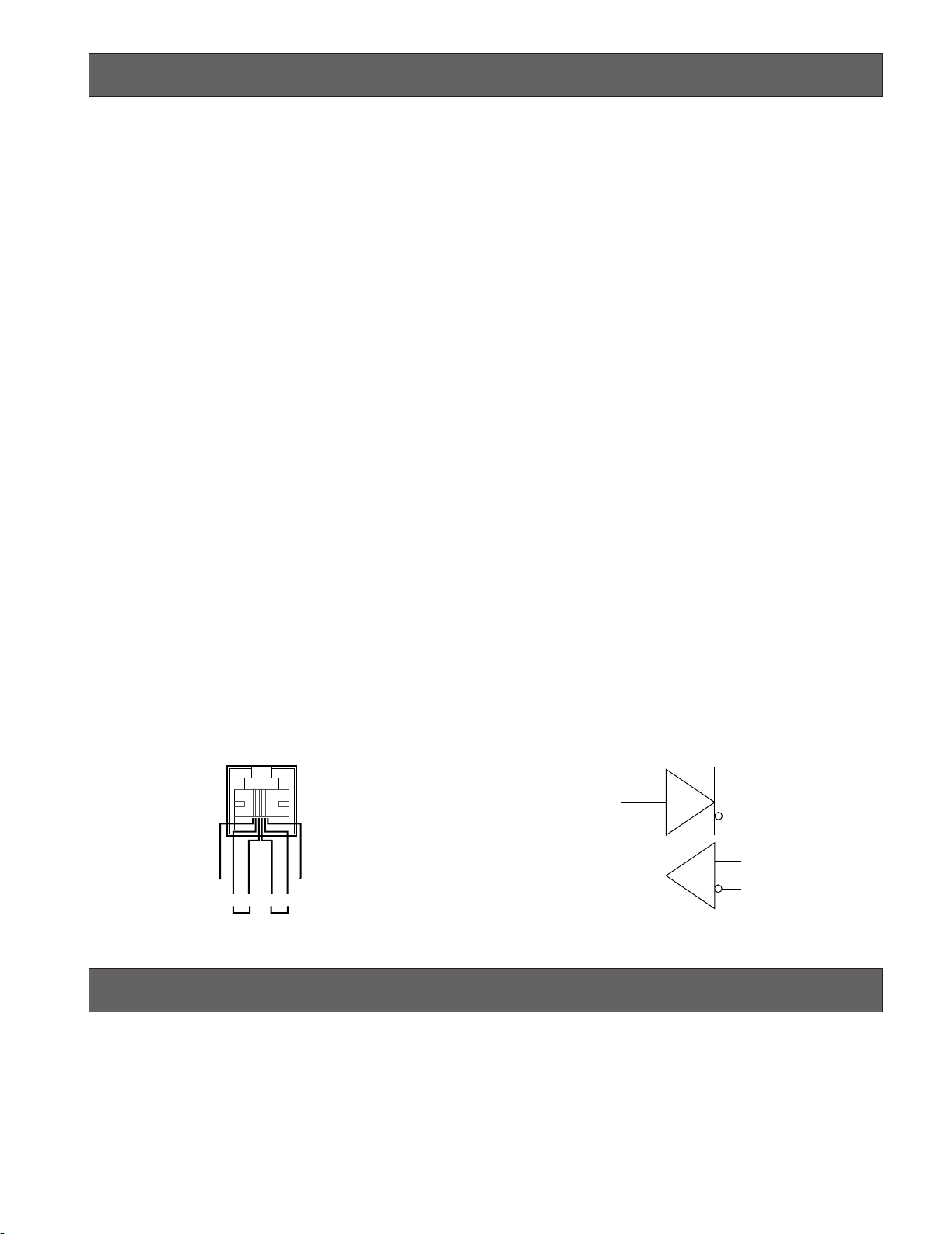
SPECIFICATIONS
● System Controller
Power Source
WV-CU950: 9 V DC, 600 mA (using the supplied AC adapter)
WV-CU650: 9 V DC, 300 mA (using the supplied AC adapter)
Supplied AC Adapter: 120 V AC, 60 Hz, 200 mA
Ethernet Port (WV-CU950 only): 10/100 Base-T, RJ-45 x 1
Data Output/Input Port: 6-conductor modular jack (RS-485, Full duplex) x2
Serial Port: 9-pin D-sub connector
Controller Number: 1 to 8 (rotary switch)
Ambient Operating Temperature: –10 °C to + 50 °C {14 °F to 122 °F}*
Unit Number Selection: 1 to 99**
Monitor Number Selection: 1 to 99**
Camera Number Selection: 1 to 256**
Dimensions
Main Unit: 290 mm (W) x 111 mm (H) x 221 mm (D)
{11-7/16 in. (W) x 4-3/8 in. (H) X 8-11/16 in. (D)}
3D Joystick Unit: 134 mm (W) x 146 mm (H) x 218 mm (D)
{5-1/4 in. (W) x 5-3/4 in. (H) x 8-9/16 in. (D)}
Weight
Main Unit: 1.3 k
3D Joystick Unit: 0.8 k
g {2.9 lbs.} (without the AC adapter)
g {1.8 lbs.}
* The performance is not guaranteed until the inside temperature rises up to 0 °C {32 °F}.
** These values are applicable in the PS·Data mode only. Refer to the operating instructions of system devices for the termi-
nal mode and Ethernet mode.
● DATA Port
RS-485 Port
System controller’s rear panel
GND GND
TBTARBRA
IN OUT
Internal block
TA
TB
RA
RB
STANDARD ACCESSORIES
Operating Instructions (This Document) ................................ 1 pc.
The following parts are used during installation procedures.
AC Adapter (UL Listed, Parts No: N0JBEF000001) ............... 1 pc.
6-conductor Modular Cable (3 m) .......................................... 1 pc.
87
Page 88

Panasonic System Solutions Company,
Unit Company of Panasonic Corporation of North America
Security Systems
www.panasonic.com/security
For customer support, call 1.877.733.3689
Executive Office: Three Panasonic Way 2H-2, Secaucus, New Jersey 07094
Zone Office
Three Panasonic Way, Secaucus, New Jersey 07094
Eastern:
Central: 1707 N. Randal Road, Elgin, IL 60123
Southern: 1225 Northbrook Parkway, Suwanee, GA 30024
Western: 6550 Katella Ave., Cypress, CA 90630
Panasonic Canada Inc.
5770 Ambler Drive,Mississauga,
Ontario, L4W 2T3 Canada (905)624-5010
http://www.panasonic.ca
Panasonic Sales Company
Division of Panasonic Puerto Rico Inc.
San Gabriel Industrial Park 65th Infantry Ave. KM. 9.5 Carolina
P.R. 00985(809)750-4300
© 2005 Matsushita Electric Industrial Co., Ltd. All Rights Reserved. N0504-4045 3TR002330EAA Printed in Japan
 Loading...