

Panasonic WV-CW484F, WV-CW484F-15, WV-CW484S, WV-CW484FK, WV-CW484SK Operating Instructions Manual
Before attempting to connect or operate this product,
please read these instructions carefully and save this manual for future use.
No model number suffix is shown in this manual.
(Lens is option.)
WV-CW484F is shown above.
Color CCTV Cameras
Operating Instructions
Model No. WV-CW484 Series
2
The lightning flash with arrowhead symbol, within an equilateral triangle, is intended to alert the
user to the presence of uninsulated "dangerous voltage" within the
product's enclosure that may be
of sufficient magnitude to constitute a risk of electric shock to
persons.
The exclamation point within an
equilateral triangle is intended to
alert the user to the presence of
important operating and maintenance (servicing) instructions in
the literature accompanying the
appliance.
The serial number of this product may be found
on the surface of the unit.
You should note the serial number of this unit in
the space provided and retain this book as a
permanent record of your purchase to aid identification in the event of theft.
Model No.
Serial No.
SA 1966
SA 1965
WARNING:
• This apparatus must be earthed.
• To prevent fire or electric shock hazard, do not expose this apparatus to rain or moisture.
• The apparatus should not be exposed to dripping or splashing and that no objects filled with liquids, such
as vases, should be placed on the apparatus.
• All work related to the installation of this product should be made by qualified service personnel or system
installers.
• The connections should comply with local electrical code.
NOTE: This equipment has been tested and found
to comply with the limits for a Class A digital
device, pursuant to Part 15 of the FCC Rules.
These limits are designed to provide reasonable
protection against harmful interference when the
equipment is operated in a commercial environment. This equipment generates, uses, and can
radiate radio frequency energy and, if not installed
and used in accordance with the instruction manual, may cause harmful interference to radio communications.
Operation of this equipment in a residential area is
likely to cause harmful interference in which case
the user will be required to correct the interference
at his own expense.
FCC Caution: To assure continued compliance,
(example - use only shielded interface cables
when connecting to computer or peripheral
devices). Any changes or modifications not
expressly approved by the party responsible for
compliance could void the user’s authority to operate this equipment.
For U.S.A
CAUTION: TO REDUCE THE RISK OF ELECTRIC SHOCK,
DO NOT REMOVE COVER (OR BACK).
NO USER-SERVICEABLE PARTS INSIDE.
REFER SERVICING TO QUALIFIED SERVICE PERSONNEL.
CAUTION
RISK OF ELECTRIC
SHOCK DO NOT OPEN
This Class A digital apparatus complies with
Canadian ICES-003.
For Canada

3
Important Safety Instructions
1) Read these instructions.
2) Keep these instructions.
3) Heed all warnings.
4) Follow all instructions.
5) Do not use this apparatus near water.
6) Clean only with dry cloth.
7) Do not block any ventilation openings. Install in accordance with the manufacturer's
instructions.
8) Do not install near any heat sources such as radiators, heat registers, stoves, or other
apparatus (including amplifiers) that produce heat.
9) Do not defeat the safety purpose of the polarized or grounding-type plug. A polarized plug
has two blades with one wider than the other. A grounding type plug has two blades and a
third grounding prong. The wide blade or the third prong are provided for your safety. If the
provided plug does not fit into your outlet, consult an electrician for replacement of the
obsolete outlet.
10) Protect the power cord from being walked on or pinched particularly at plugs, convenience
receptacles, and the point where they exit from the apparatus.
11) Only use attachments/accessories specified by the manufacturer.
12) Use only with the cart, stand, tripod, bracket, or table specified by the manufacturer, or
sold with the apparatus. When a cart is used, use caution when moving the cart/apparatus
combination to avoid injury from tip-over.
13) Unplug this apparatus during lightning storms or when unused for long periods of time.
14) Refer all servicing to qualified service personnel. Servicing is required when the apparatus
has been damaged in any way, such as power-supply cord or plug is damaged, liquid has
been spilled or objects have fallen into the apparatus, the apparatus has been exposed to
rain or moisture, does not operate normally, or has been dropped.
S3125A

4
Limitation of Liability
THIS PUBLICATION IS PROVIDED "AS IS"
WITHOUT WARRANTY OF ANY KIND,
EITHER EXPRESS OR IMPLIED, INCLUDING
BUT NOT LIMITED TO, THE IMPLIED WARRANTIES OF MERCHANTABILITY, FITNESS
FOR ANY PARTICULAR PURPOSE, OR
NON-INFRINGEMENT OF THE THIRD
PARTY'S RIGHT.
Disclaimer of Warranty
IN NO EVENT SHALL MATSUSHITA ELECTRIC INDUSTRIAL CO., LTD. BE LIABLE TO
ANY PARTY OR ANY PERSON, EXCEPT FOR
REPLACEMENT OR REASONABLE MAINTENANCE OF THE PRODUCT, FOR THE
CASES, INCLUDING BUT NOT LIMITED TO
BELOW:
(1) ANY DAMAGE AND LOSS, INCLUDING
WITHOUT LIMITATION, DIRECT OR
INDIRECT, SPECIAL, CONSEQUENTIAL
OR EXEMPLARY, ARISING OUT OF OR
RELATING TO THE PRODUCT;
(2) PERSONAL INJURY OR ANY DAMAGE
CAUSED BY INAPPROPRIATE USE OR
NEGLIGENT OPERATION OF THE USER;
(3) UNAUTHORIZED DISASSEMBLE,
REPAIR OR MODIFICATION OF THE
PRODUCT BY THE USER;
(4) INCONVENIENCE OR ANY LOSS ARIS-
ING WHEN IMAGES ARE NOT DISPLAYED, DUE TO ANY REASON OR
CAUSE INCLUDING ANY FAILURE OR
PROBLEM OF THE PRODUCT;
(5) ANY PROBLEM, CONSEQUENTIAL
INCONVENIENCE, OR LOSS OR DAMAGE, ARISING OUT OF THE SYSTEM
COMBINED BY THE DEVICES OF THIRD
PARTY;
(6) ANY CLAIM OR ACTION FOR DAM-
AGES, BROUGHT BY ANY PERSON OR
ORGANIZATION BEING A PHOTOGENIC SUBJECT, DUE TO VIOLATION
OF PRIVACY WITH THE RESULT OF
THAT SURVEILLANCE-CAMERA'S PICTURE, INCLUDING SAVED DATA, FOR
SOME REASON, BECOMES PUBLIC OR
IS USED FOR THE PURPOSE OTHER
THAN SURVEILLANCE.
THIS PUBLICATION COULD INCLUDE
TECHNICAL INACCURACIES OR TYPOGRAPHICAL ERRORS. CHANGES ARE
ADDED TO THE INFORMATION HEREIN, AT
ANY TIME, FOR THE IMPROVEMENTS OF
THIS PUBLICATION AND/OR THE CORRESPONDING PRODUCT (S).

5
Preface
Panasonic's WV-CW484 series cameras (WV-CW484F/WV-CW484S/WV-CW484FK/WVCW484SK) introduce high picture quality by use of Super-Dynamic 1/3 inch CCD and digital
signal processing LSIs.
• WV-CW484F: This is a model with x2 varifocal lens. Mounting bracket and ceiling mount
bracket are optional.
• WV-CW484S: This is a model with x2 varifocal lens. Mounting bracket is supplied, but ceiling mount bracket are optional.
• WV-CW484FK: Lens, mounting bracket, and ceiling mount bracket are optional.
• WV-CW484SK: Lens is optional. Mounting bracket is supplied, but ceiling mount bracket
are optional.
Features
• Super Dynamic 3: 128x with zone-free brightness detection
• High sensitivity: 0.16 lx {0.016 footcandle} at F1.4 in B/W mode, 1.5 lx {0.15 footcandle} at
F1.4 in color mode
With the optional Dome Cover WV-CW4C, 0.08 lx {0.008 footcandle} in B/W mode and
0.6 lx {0.06 footcandle} in color mode become available.
• Auto nighttime switching to Black and White Mode
The camera can be configured to switch to the black and white mode automatically under
low light conditions for clear images, even at night.
• High resolution: 540 TV lines typical, 520 TV lines minimum
• Sensitivity enhancement: Up to 10x AUTO/32x FIX
• Synchronization: VD2/ LINE-LOCK/INTERNAL
• Auto-Back-Focus (flange-back (back focal) length adjustment): 1-push adjustment
(local/remote), manual adjustment (local/remote), automatic adjustment at BW/CL transition
Setup using an optional system controller is also available.
• Light control: ALC
• Miscellaneous: Privacy zone setting, Video motion detection, etc.

6
CONTENTS
Important Safety Instructions ........................................................................................................3
Limitation of Liability ......................................................................................................................4
Disclaimer of Warranty ..................................................................................................................4
Preface ..........................................................................................................................................5
Features ........................................................................................................................................5
Precautions ...................................................................................................................................7
Major Operating Controls and Their Functions ...........................................................................10
Lens Mounting (WV-CW484FK, CW484SK) ...............................................................................12
Installations .................................................................................................................................13
Image Adjustment .......................................................................................................................21
Connections ................................................................................................................................23
Flange-back (Back Focus) Adjustment .......................................................................................26
About Setup Menus .....................................................................................................................27
Setting Procedures ......................................................................................................................31
Troubleshooting ..........................................................................................................................45
Specifications ..............................................................................................................................47
Optional Accessories ..................................................................................................................48
Standard Accessories .................................................................................................................48
Optional Accessories ................................................................................................................. 48
7
Precautions
This apparatus has no power switch.
Power is supplied from an external 12 V
DC/24 V AC power-supply device. Refer to
service personnel for how to turn on/off the
power.
To keep on using with stable performance
• Parts of this product may deteriorate and
it may shorten lifetime of this product
when using in locations subject to high
temperatures and high humidity. Do not
expose the product to direct heat such
from a heater.
• Use the appliance at temperature within
–10 °C to +50 °C {14 °F - 122°F} and
humidity below 90 %. (When using the
appliance without turning the power off)
With the optional Heater Unit WV-CW4H,
this apparatus can be used at temperature within –30 °C to +50 °C {–22 °F to
122 °F} and humidity below 90 %.
Do not drop metallic parts through slots.
This could permanently damage the apparatus. Turn the power off immediately and contact qualified service personnel for service.
Do not rub the edges of metal parts with
your hand.
Failure to observe this may cause injury.
Do not attempt to disassemble the camera.
To prevent electric shock, do not remove
screws or covers.
There are no user-serviceable parts inside.
Ask qualified service personnel for servicing.
Handle the camera with care.
Do not abuse the camera. Avoid striking,
shaking, etc. The camera could be damaged
by improper handling or storage.
Do not touch the dome cover with your
bare hands.
A dirty dome cover causes deterioration of
picture quality.
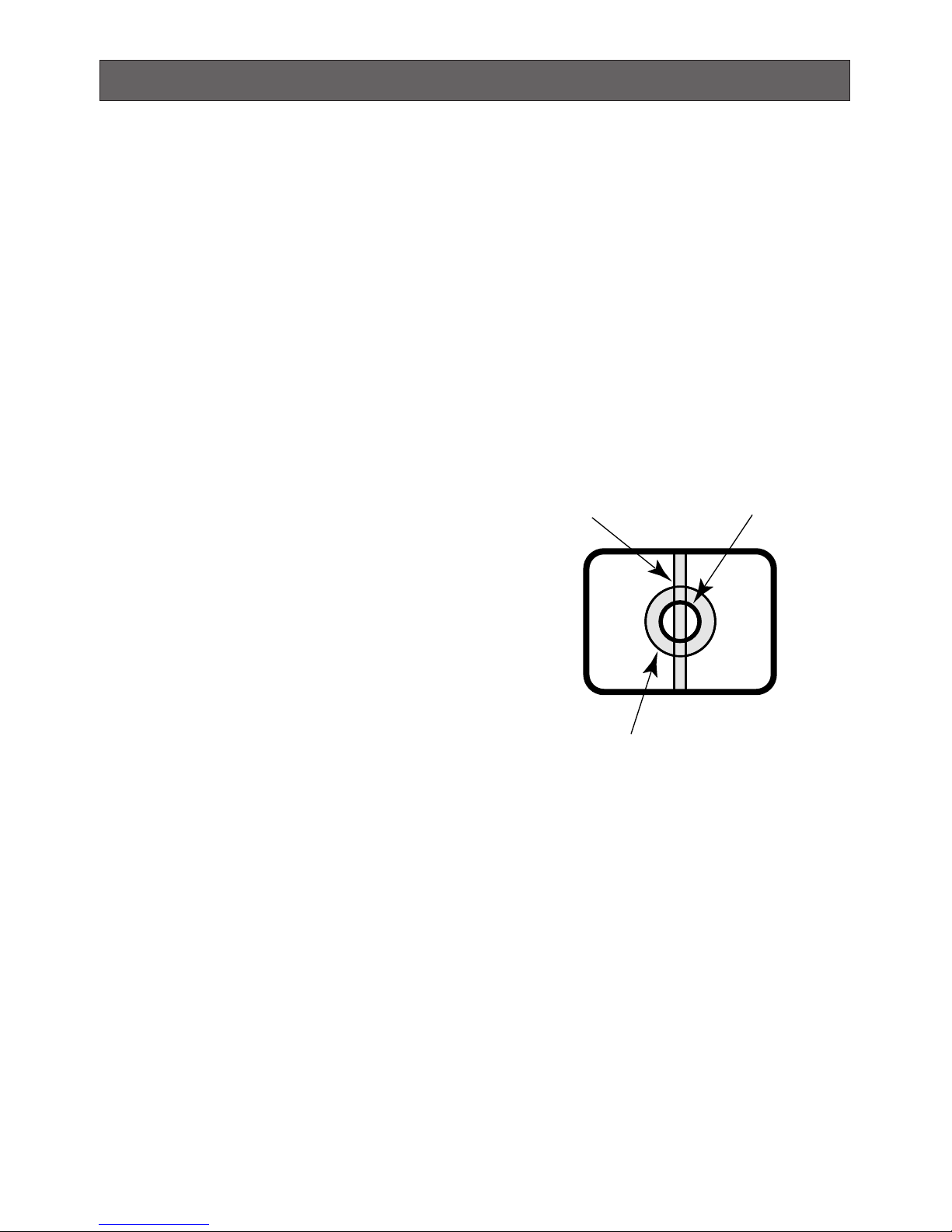
Do not aim the apparatus at strong light
sources.
A light source such as a spot light causes a
blooming (light bleeding) or a smear (vertical
lines).
Cleaning the camera body
Turn the power off when cleaning of the camera. Use a dry cloth to clean the camera.
Do not use strong abrasive detergent when
cleaning the camera body. When the dirt is
hard to remove, use a mild detergent and
wipe gently. Then, wipe with a dry cloth.
Otherwise, it may cause discoloration. When
using a chemical cloth for cleaning, read the
caution provided with the chemical cloth
product.
Smear
Bright subject
Blooming
8
Do not use strong or abrasive detergents
when cleaning the camera body.
Use a dry cloth to clean the camera when
dirty. When the dirt is hard to remove, use a
mild detergent and wipe gently. Then wipe
off the remaining detergent with a dry cloth.
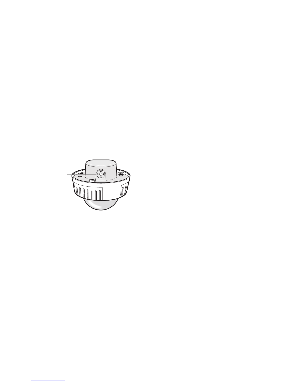
About the dehumidifying device
• The camera has dehumidifying device to
keep the inside at low moisture level,
preventing condensation and quickly dissipating dew if produced.
• Dew may be produced depending on the
conditions of temperature, humidity,
winds, and rain, and it may take time to
dehumidify.
• Never seal the surfaces of the dehumidifying device.
Turn the circuit breaker off which supplies
the camera with the power when abnormal
conditions are encountered.
Observe the following for installation.
• This apparatus is designed to be
installed under eaves. Install this apparatus under eaves to avoid direct sunlight.
• If this apparatus is installed outdoors
without eaves, ensure the same circumstances as being under eaves.
Avoid installing in the following locations.
• Locations where a chemical agent is
used such as a swimming pool
• Locations subject to steam and oil smoke
such as a kitchen
• Locations near flammable gas or vapor
• Locations where radiation or x-ray emissions are produced
• Locations subject to strong magnetic
field or radio waves
• Locations where corrosive gas is produced
• Locations where it may be damaged by
briny air such as seashores
• Locations where the temperature is not
within –10 °C - +50 °C {14 °F - 122°F}.
• Locations subject to vibrations (This
product is not designed for on-vehicle
use.)
Installing place
Contact your dealer for assistance if you are
unsure of an appropriate place in your particular environment.
Make sure that the installation area is strong
enough to hold the camera, such as a concrete ceiling.
When the installation area is not strong
enough, reinforce and strengthen it or use
Mounting Bracket WV-Q114 (option) or
Ceiling Mount Bracket WV-Q166 (option).
Do not install the camera in a humid or
dust-laden environment.
Otherwise, lifetime of the internal parts may
be shortened.
Radio interference
When the camera is used near TV/radio
antenna, strong electric field or magnetic
field (near a motor or a transformer), images
may be distorted and noise sound may be
produced.
Mounting screws
Only the fixing screws are provided to fix the
camera with the provided mounting bracket.
It is necessary to procure screws or bolts to
mount the camera. Prepare them according
to the material and strength of the area
where the camera is to be installed. The
screws and bolts must be tightened with an
appropriate tightening torque according to
the material and strength of the installation
area.
Dehumidifying
device

9
Consumable parts
Contact your dealer for replacement of the
following part when the time comes:
Cooling fan needs replacement after around
30 000 hours of operation.
Do not operate the camera beyond the
specified temperature, humidity or power
source ratings.
Use the camera at temperatures within
–10 °C to +50 °C {14 °F - 122°F}, and humidity below 90 %. The input power source is
24 V AC or 12 V DC.
10
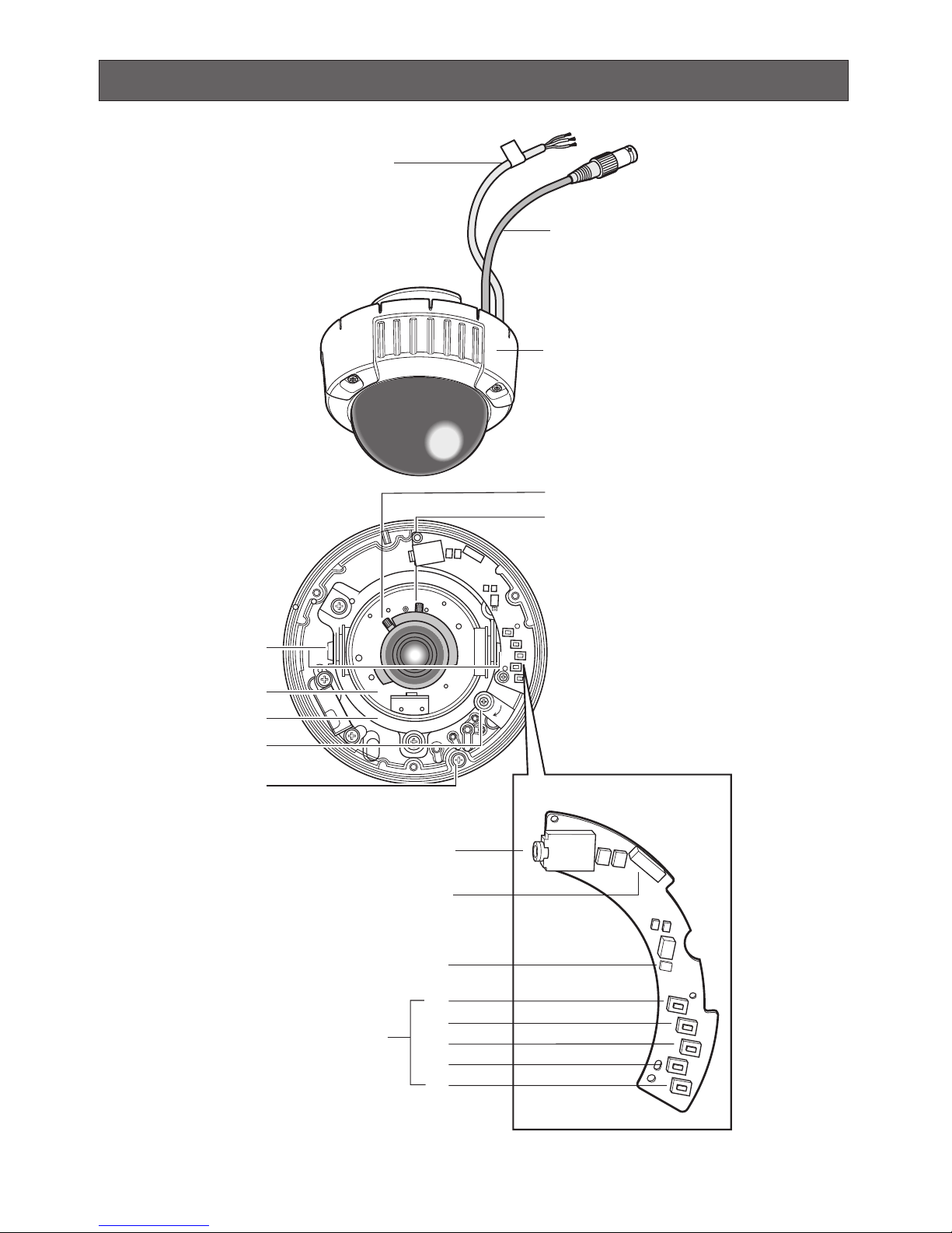
Major Operating Controls and Their Functions
q
w
e
r
t
y
!1
!2
!3
!4
!6
!7
!8
!9
!55
u
i
o
!0

11
q Power cable (12 V DC or 24 V AC)
Cautions:
1. Connect to 12 V DC (10.5 - 16 V) or
24 V AC (19.5 V - 28 V) class 2
power supply only. Make sure to
connect the grounding lead to the
GND terminal when the power is
supplied from a 24 V AC power
source.
2. To prevent fire or electric shock hazard, use a UL listed cable (VW-1,
style 1007) for the Input Terminal.
w Video output cable with BNC connec-
tor
Connects with the video connector of the
monitor.
e Dome cover
r Focus lock lever (WV-CW484F,
WV-CW484S)
Fixes the focus position.
t Zoom lock lever (WV-CW484F,
WV-CW484S)
Fixes the zoom position.
y Tilting lock screw
Fixes the tilting position.
u Azimuth (Angle adjuster)
Shoots in a straight-angle field of view
when aiming at an object in a slanting
direction even if the tilt angle has been
set.
i Panning table
Adjusts the panning angle of the camera.
o Panning lock screw
Fixes the panning position.
!0 Camera lock screw
Fixes the camera and camera attachment.
!1 Monitor output Jack (3.5 diam. mini
jack)
Connects the LCD monitor and such
devices with 3.5 diam. 2-pole L-type plug
for checking images.
!2 Optional heater connector (6 pin
female)
When an optional heater unit is installed
in the camera, the harness exiting from
the unit will be connected to this.
!3 LED indicator
Shows the ABF status.
!4 Operation buttons
!5 SET button [(SET), ABF2/MENU]
Activates an item selected in the setup
menu. Refer to p. 18 for details on the
[ABF2] button.
!4 DOWN button [(DOWN), ABF1]
Moves the cursor downward and selects
items in the setup SET UP menu.
!5 UP button (UP)
Moves the cursor upward and selects
items in the setup menu.
!6 LEFT button [(LEFT), NEAR]
Moves the cursor to the left, selects the
mode and adjusts some levels.
!7 RIGHT button [(RIGHT), NEAR]
Moves the cursor to the right, selects the
mode and adjusts some levels.
12
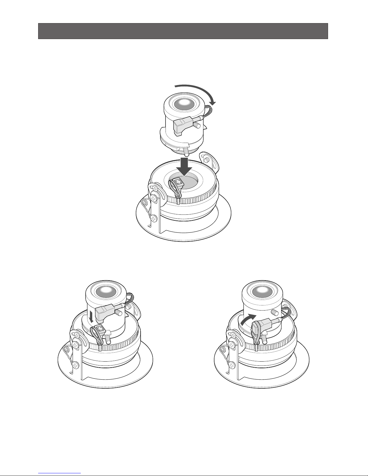
Lens Mounting (WV-CW484FK, CW484SK)
1. Before mounting the lens, remove the protection sheet from the camera.
2. Mount the optional lens to the camera by turning the lens clockwise.
3. Insert the connector of lens into the connector of camera, and bind the connectors with the
fixing band.
13
Installations
The following installation should be made by qualified service personnel or system installers.
Important:
• Prepare four fixing screws to be used to mount the provided camera attachment according
to the material of the area where the attachment is to be installed.
Recommended tightening torque is as follows.
M4: 1.6 N·m {16 kgf·cm}
• Do not use wood screws to fix the camera mounting bracket (option) since they are not
strong enough to support the weight of the camera and the bracket.
• When using the provided camera attachment, make sure that either of the arrow marks
faces upward.
• When the installation area is not strong enough, reinforce and strengthen it or use Mounting
Bracket WV-Q114 (option) or Ceiling Mount Bracket WV-Q166 (option).
• Required pull-out capacity of a single screw/bolt is 196 N {20 kgf} or more.
• When using an optional mounting bracket, refer to the operating instructions of the bracket
in use.
■ Installations
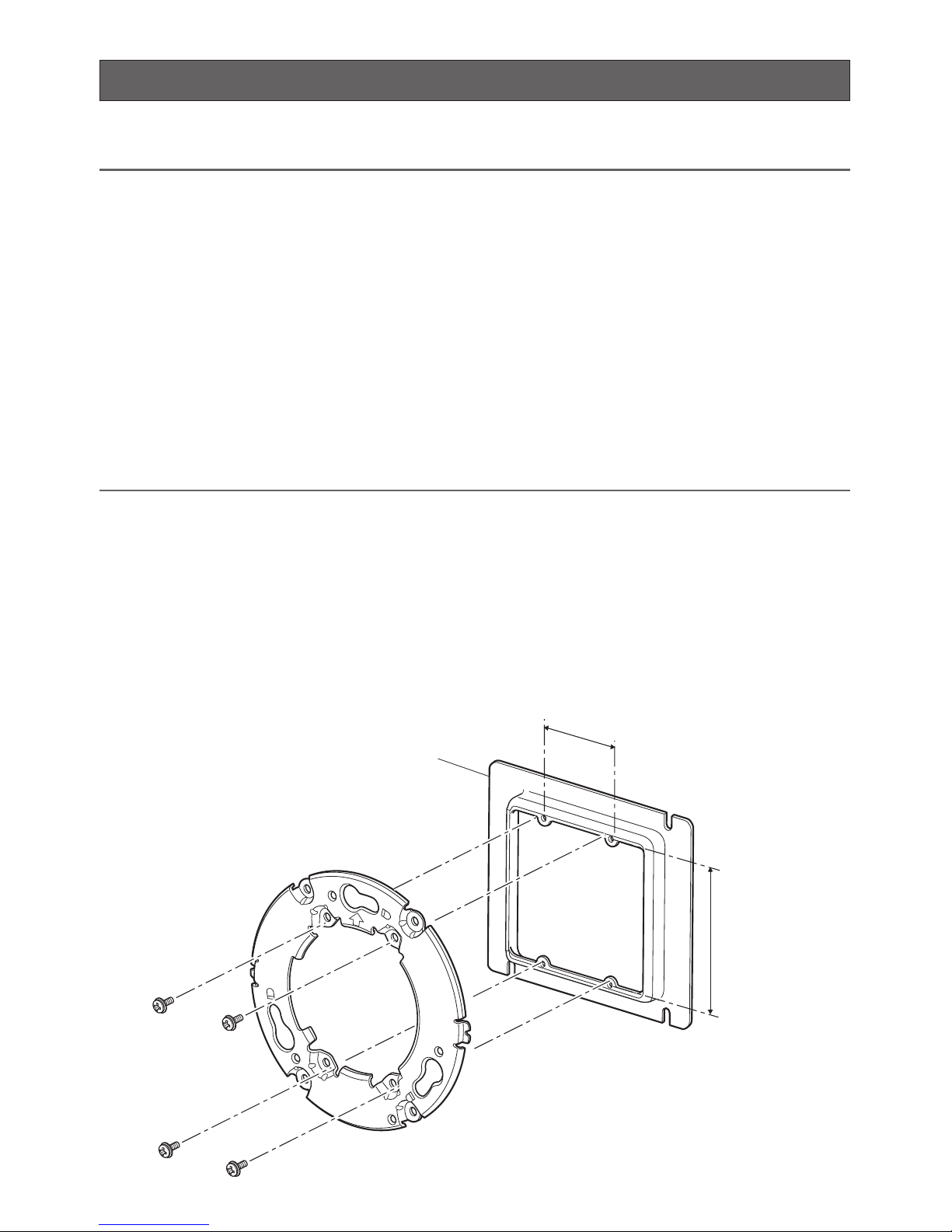
● Using a Junction Box
Secure the provided camera attachment to the two gang junction box (4 in. x 4 in.) built in a
wall or ceiling.
<Mounting hole pattern>
46 mm {1-13/16"}
Junction box
Camera attachment (provided)
83.5 mm
{3-5/16"}
14
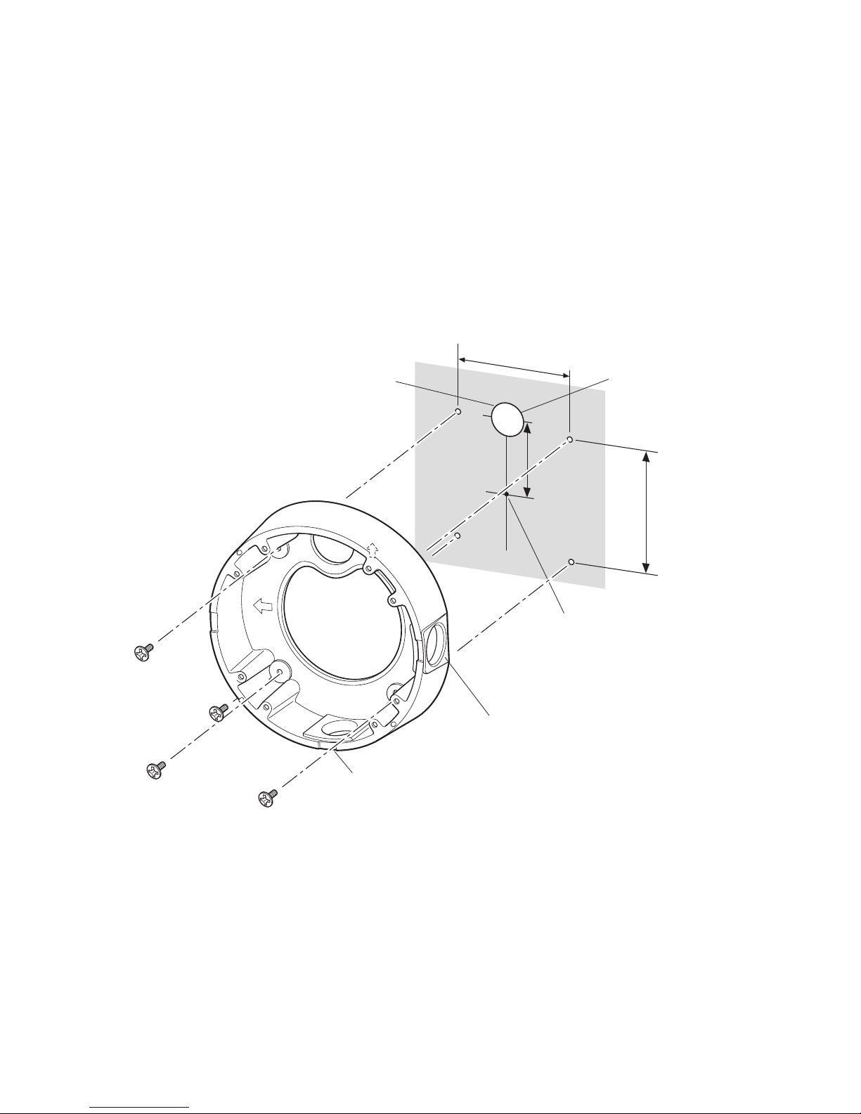
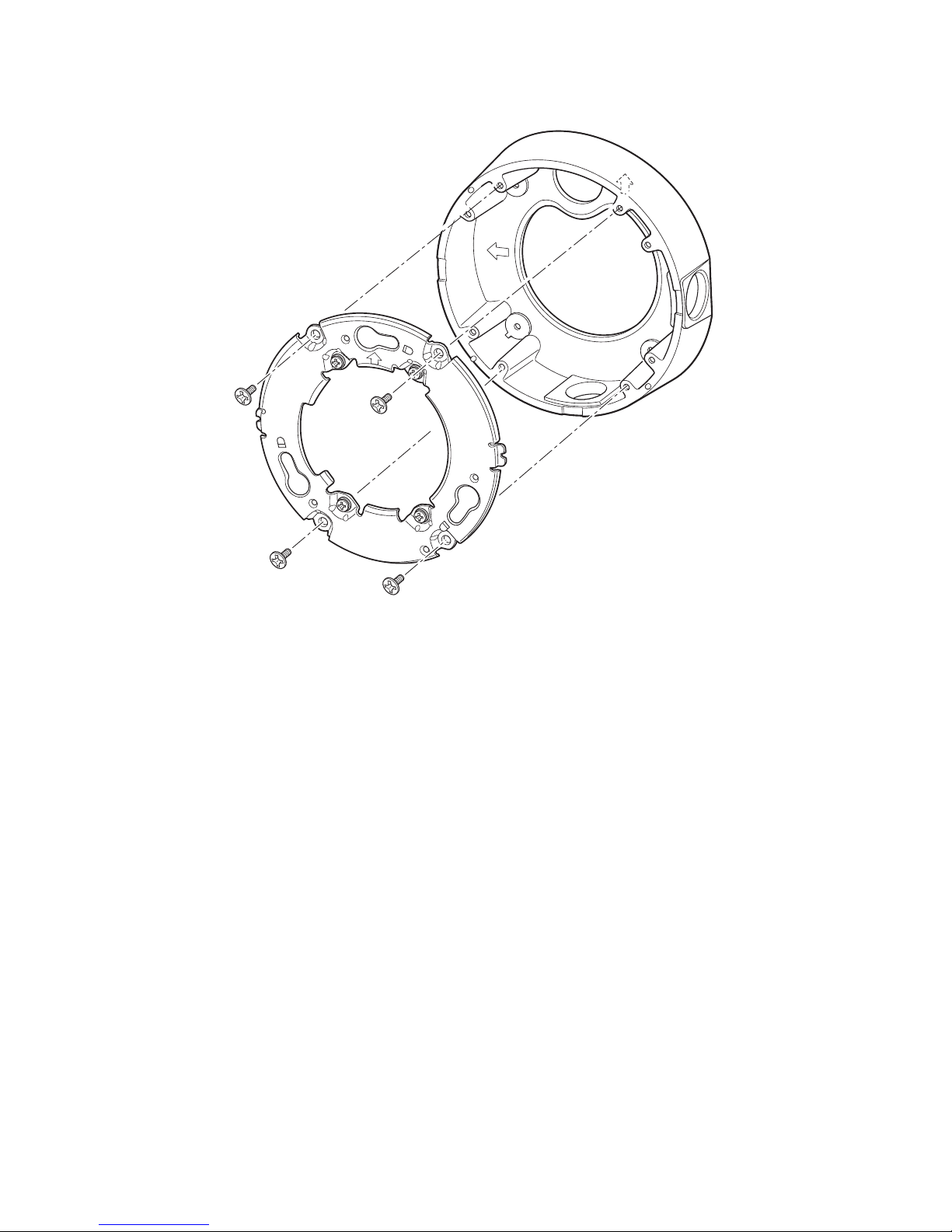
● Using Mounting Bracket WV-Q114 (Option)
• Secure the optional camera mounting bracket to wall or ceiling, and fix the provided camera attachment to the mounting bracket. (Refer to the following figures.)
Verify the camera attachment and mounting bracket are mounted firmly after screwing
them.
• When routing cables sideway or through the wall/ceiling, the mounting bracket is used.
• When routing cables sideway, open the sideway cable exit unscrewing the lid by use of a
hexagon wrench. Screw the detached lid to the cable access hole on the bottom of the
bracket.
• Make sure that either of the arrow marks faces upward.
85 mm
{3-3/8"}
Bracket center
WV-Q114
Drain hole*
* For wall mounting, face the
drain hole downward.
51 mm
{2"}
Sideway cable exit
85 mm {3-3/8"}
<Mounting hole pattern>
TOP
TOP
TOP
Cable access hole for 3/4" pipe
Cable access hole
for 3/4" pipe
15
<Fixing the camera attachment to the mounting bracket>
Camera attachment (provided)
WV-Q114
TOP
TOP
TOP
 Loading...