

Page 1
Colour CCTV Cameras
Operating Instructions
Model Nos. WV-CW484F
WV-CW480S
ENGLISHDEUTSCHFRANÇAIS
ESPAÑOL
WV-CW484F is shown above.
Before attempting to connect or operate this product,
please read these instructions carefully and save this manual for future use.
No model number suffix is shown in this manual.
ITALIANOкмллдав
Page 2
ENGLISH VERSION
WARNING:
• This apparatus must be earthed.
• Apparatus shall be connected to a mains socket outlet with a protective earthing connection.
• The mains plug or an appliance coupler shall
remain readily operable.
• All work related to the installation of this product should be made by qualified service personnel or system installers.
• The connections should comply with local electrical code.
CAUTION
RISK OF ELECTRIC
SHOCK DO NOT OPEN
CAUTION: TO REDUCE THE RISK OF ELECTRIC SHOCK,
DO NOT REMOVE COVER (OR BACK).
NO USER-SERVICEABLE PARTS INSIDE.
REFER SERVICING TO QUALIFIED SERVICE PERSONNEL.
The lightning flash with arrowhead symbol, within an equilateral triangle, is intended to alert
the user to the presence of uninsulated "dangerous voltage"
within the product's enclosure
that may be of sufficient magnitude to constitute a risk of electric shock to persons.
The exclamation point within an
equilateral triangle is intended to
alert the user to the presence of
important operating and maintenance (servicing) instructions in
the literature accompanying the
appliance.
Turn the power off at the mains
to disconnect the main power for
all unit.
CAUTION
:
An ALL-POLE MAINS SWITCH with a contact
separation of at least 3 mm in each pole shall be
incorporated in the electrical installation of the
building.
FOR YOUR SAFETY PLEASE READ THE FOLLOWING TEXT CAREFULLY.
WARNING: This apparatus must be earthed.
IMPORTANT
The wires in this mains lead are coloured in accordance with the following code.
Green-and-yellow: Earth
Blue: Neutral
Brown: Live
As the colours of the wire in the mains lead of this
appliance may not correspond with the coloured
markings identifying the terminals in your plug, proceed as follows.
The wire which is coloured green-and-yellow
must be connected to the terminal in the plug which
is marked with the letter E or by the earth symbol I
or coloured green or green-and-yellow.
The wire which is coloured blue must be connected to the terminal in the plug which is marked with
the letter N or coloured black.
The wire which is coloured brown must be connected to the terminal in the plug which is marked
with the letter L or coloured red.
The serial number of this product may be found
on the surface of the unit.
You should note the serial number of this unit in
the space provided and retain this book as a
permanent record of your purchase to aid identification in the event of theft.
Model No.
Serial No.
2
Page 3

CONTENTS
Important Safety Instructions ..................................................................................................... 4
Limitation of Liability ................................................................................................................... 5
Disclaimer of Warranty ............................................................................................................... 5
Preface ....................................................................................................................................... 6
Features ..................................................................................................................................... 6
Precautions ................................................................................................................................ 7
Major Operating Controls and Their Functions .......................................................................... 10
Installations ................................................................................................................................ 12
Image Adjustment ...................................................................................................................... 20
Connections ............................................................................................................................... 22
About Setup Menus .................................................................................................................... 25
Setting Procedures ..................................................................................................................... 29
Troubleshooting ......................................................................................................................... 43
Specifications ............................................................................................................................. 44
Standard Accessories ................................................................................................................ 46
Optional Accessories ................................................................................................................. 46
ENGLISH
We declare under our sole responsibility that the product to
which this declaration relates is in conformity with the standards or other normative documents following the provisions of
Directives EEC/73/23 and EEC/89/336.
Wij verklaren als enige aansprakelijke, dat het product waarop
deze verklaring betrekking heeft, voldoet aan de volgende
normen of andere normatieve documenten, overeenkomstig de
bepalingen van Richtlijnen 73/23/EEC en 89/336/EEC.
Vi erklærer os eneansvarlige for, at dette produkt, som denne
deklaration omhandler, er i overensstemmelse med standarder
eller andre normative dokumenter i følge bestemmelserne i
direktivene 73/23/EEC og 89/336/EEC.
Vi deklarerar härmed värt fulla ansvar för att den produkt till
vilken denna deklaration hänvisar är i överensstämmelse med
standarddokument, eller andra normativa dokument som
framställs i EEC-direktiv nr. 73/23 och 89/336.
Ilmoitamme yksinomaisella vastuullamme, että tuote, jota tämä
ilmoitus koskee, noudattaa seuraavia standardeja tai muita
ohjeellisia asiakirjoja, jotka noudattavat direktiivien 73/23/EEC
ja 89/336/EE. säädöksiä.
Vi erklærer oss alene ansvarlige for at produktet som denne
erklæringen gjelder for, er i overensstemmelse med følgende
normer eller andre normgivende dokumenter som følger
bestemmelsene i direktivene 73/23/EEC og 89/336/EEC.
3
Page 4

Important Safety Instructions
1) Read these instructions.
2) Keep these instructions.
3) Heed all warnings.
4) Follow all instructions.
5) Clean only with dry cloth.
6) Do not block any ventilation openings. Install in accordance with the manufacturer's
instructions.
7) Do not install near any heat sources such as radiators, heat registers, stoves, or other
apparatus (including amplifiers) that produce heat.
8) Do not defeat the safety purpose of the polarized or grounding-type plug. A polarized plug
has two blades with one wider than the other. A grounding type plug has two blades and a
third grounding prong. The wide blade or the third prong are provided for your safety. If the
provided plug does not fit into your outlet, consult an electrician for replacement of the
obsolete outlet.
9) Protect the power cord from being walked on or pinched particularly at plugs, convenience
receptacles, and the point where they exit from the apparatus.
10) Only use attachments/accessories specified by the manufacturer.
11) Use only with the cart, stand, tripod, bracket, or table specified by the manufacturer, or
sold with the apparatus. When a cart is used, use caution when moving the cart/apparatus
combination to avoid injury from tip-over.
S3125A
12) Unplug this apparatus during lightning storms or when unused for long periods of time.
4
Page 5

Limitation of Liability
THIS PUBLICATION IS PROVIDED "AS IS"
WITHOUT WARRANTY OF ANY KIND,
EITHER EXPRESS OR IMPLIED, INCLUDING
BUT NOT LIMITED TO, THE IMPLIED WARRANTIES OF MERCHANTABILITY, FITNESS
FOR ANY PARTICULAR PURPOSE, OR
NON-INFRINGEMENT OF THE THIRD
PARTY'S RIGHT.
Disclaimer of Warranty
IN NO EVENT SHALL MATSUSHITA ELECTRIC INDUSTRIAL CO., LTD. BE LIABLE TO
ANY PARTY OR ANY PERSON, EXCEPT FOR
REPLACEMENT OR REASONABLE MAINTENANCE OF THE PRODUCT, FOR THE
CASES, INCLUDING BUT NOT LIMITED TO
BELOW:
(1) ANY DAMAGE AND LOSS, INCLUDING
WITHOUT LIMITATION, DIRECT OR
INDIRECT, SPECIAL, CONSEQUENTIAL
OR EXEMPLARY, ARISING OUT OF OR
RELATING TO THE PRODUCT;
(2) PERSONAL INJURY OR ANY DAMAGE
CAUSED BY INAPPROPRIATE USE OR
NEGLIGENT OPERATION OF THE USER;
(3) UNAUTHORIZED DISASSEMBLE,
REPAIR OR MODIFICATION OF THE
PRODUCT BY THE USER;
(4) INCONVENIENCE OR ANY LOSS ARIS-
ING WHEN IMAGES ARE NOT DISPLAYED, DUE TO ANY REASON OR
CAUSE INCLUDING ANY FAILURE OR
PROBLEM OF THE PRODUCT;
THIS PUBLICATION COULD INCLUDE
TECHNICAL INACCURACIES OR TYPOGRAPHICAL ERRORS. CHANGES ARE
ADDED TO THE INFORMATION HEREIN, AT
ANY TIME, FOR THE IMPROVEMENTS OF
THIS PUBLICATION AND/OR THE CORRESPONDING PRODUCT (S).
(5) ANY PROBLEM, CONSEQUENTIAL
INCONVENIENCE, OR LOSS OR DAMAGE, ARISING OUT OF THE SYSTEM
COMBINED BY THE DEVICES OF THIRD
PARTY;
(6) ANY CLAIM OR ACTION FOR DAM-
AGES, BROUGHT BY ANY PERSON OR
ORGANIZATION BEING A PHOTOGENIC SUBJECT, DUE TO VIOLATION
OF PRIVACY WITH THE RESULT OF
THAT SURVEILLANCE-CAMERA'S PICTURE, INCLUDING SAVED DATA, FOR
SOME REASON, BECOMES PUBLIC OR
IS USED FOR THE PURPOSE OTHER
THAN SURVEILLANCE.
5
Page 6

Preface
Panasonic's WV-CW484F and WV-CW480S cameras introduce high picture quality by use of
Super-Dynamic 1/3 inch CCD and digital signal processing LSIs.
• WV-CW484F: This is a model with 2x variable focal lens. Mounting bracket and ceiling
mount bracket are optional. (Power source: 12 V DC/24 V AC)
• WV-CW480S: This is a model with 2x variable focal lens. Mounting bracket is provided, but
ceiling mount bracket is optional. (Power source: 220 V to 240 V AC)
Features
• Super Dynamic 3: 160x with zone-free brightness detection
• High sensitivity: 0.08 lx at F1.4 in B/W mode, 0.6 lx at F1.4 in colour mode
With the optional Smoke Dome Cover WV-CW4S, 0.16 lx in B/W mode and 1.5 lx in colour
mode become available.
• Auto nighttime switching to Black and White Mode
The camera can be configured to switch to the black and white mode automatically under
low light conditions for clear images, even at night.
• High resolution: 540 TV lines typical, 520 TV lines minimum
• Sensitivity enhancement: Up to 10x AUTO/32x FIX
• Synchronization: Multiplexed vertical drive (VD2), Line-locked (LL), or Internal (INT)
• Auto-Back-Focus (flange-back (back focal) length adjustment): 1-push adjustment
(local/remote), manual adjustment (local/remote), automatic adjustment at BW/CL transition
Setup using an optional system controller is also available.
• Light control: ALC
• Miscellaneous: Privacy zone setting, Video motion detection, etc.
6
Page 7
Precautions
This apparatus has no power switch.
Power is supplied from an external 12 V DC/
24 V AC (WV-CW484F) or 220 V to 240 V AC
(WV-CW480S) power-supply device. Refer to
service personnel for how to turn on/off the
power.
To keep on using with stable performance
• Parts of this product may deteriorate and
it may shorten lifetime of this product
when using in locations subject to high
temperatures and high humidity. Do not
expose the product to direct heat such
from a heater.
• Use the appliance at temperature within
–10 °C to +50 °C and humidity below
90 %. (When using the appliance without
turning the power off)
With the optional Heater Unit WV-CW4H,
this apparatus can be used at temperature within –30 °C to +50 °C and humidity
below 90 %.
Do not drop metallic parts through slots.
This could permanently damage the apparatus. Turn the power off immediately and contact qualified service personnel for service.
Do not rub the edges of metal parts with
your hand.
Failure to observe this may cause injury.
Do not attempt to disassemble the camera.
To prevent electric shock, do not remove
screws or covers.
There are no user-serviceable parts inside.
Ask qualified service personnel for servicing.
Do not touch the dome cover with your
bare hands.
A dirty dome cover causes deterioration of
picture quality.
Cleaning the camera body
Turn the power off when cleaning the camera. Use a dry cloth to clean the camera. Do
not use strong abrasive detergent when
cleaning the camera body. When the dirt is
hard to remove, use a mild detergent and
wipe gently. Then, wipe off the remaining
detergent with a dry cloth.
Otherwise, it may cause discolouration.
When using a chemical cloth for cleaning,
read the caution provided with the chemical
cloth product.
Discolouration on the CCD colour filter
When continuously shooting a bright light
source such as a spotlight, the colour filter of
the CCD may have deteriorated and it may
cause discolouration. Even when changing
the fixed shooting direction after continuously
shooting a spotlight for a certain period, the
discolouration may remain.
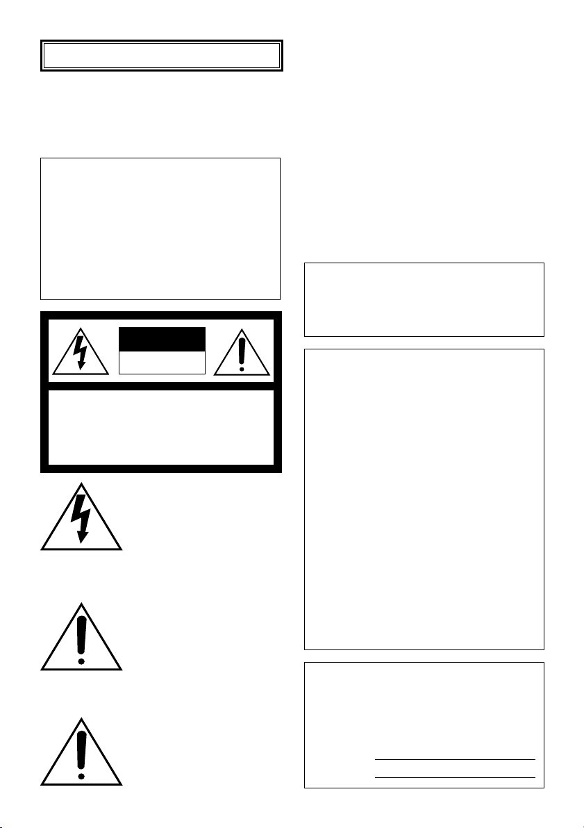
Do not aim the apparatus at strong light
sources.
A light source such as a spot light causes a
blooming (light bleeding) or a smear (vertical
lines).
Smear
Bright subject
Handle the camera with care.
Do not abuse the camera. Avoid striking,
shaking, etc. The camera could be damaged
by improper handling or storage.
Blooming
7
Page 8
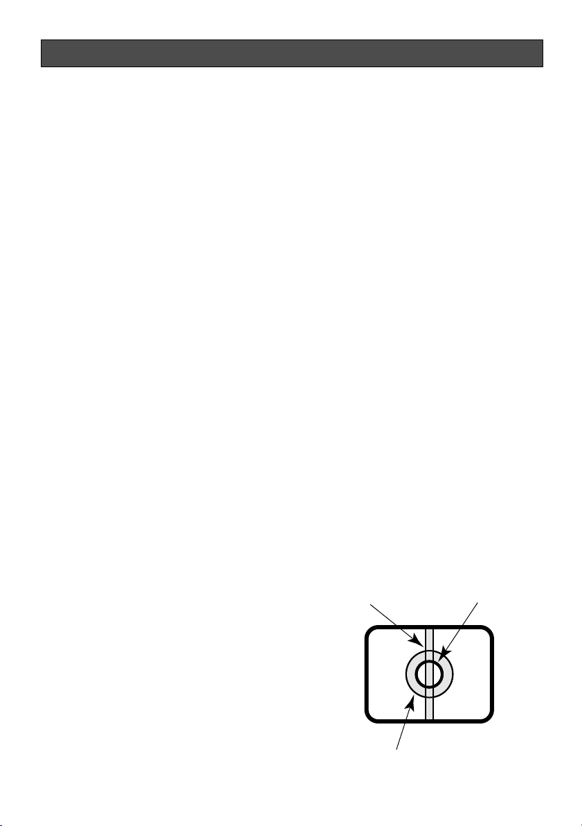
About the dehumidifying device
• The camera has dehumidifying device to
keep the inside at low moisture level,
preventing condensation and quickly dissipating dew if produced.
• Dew may be produced depending on the
conditions of temperature, humidity,
winds, and rain, and it may take time to
dehumidify.
• Never seal the surfaces of the dehumidifying device.
Dehumidifying
device
Turn the circuit breaker off which supplies
the camera with the power when abnormal
conditions are encountered.
Observe the following for installation.
• This apparatus is designed to be
installed under eaves. Install this apparatus under eaves to avoid direct sunlight.
• If this apparatus is installed outdoors
without eaves, ensure the same circumstances as being under eaves.
Avoid installing in the following locations.
• Locations where a chemical agent is
used such as a swimming pool
• Locations subject to steam and oil smoke
such as a kitchen
• Locations near flammable gas or vapor
• Locations where radiation or x-ray emissions are produced
• Locations subject to strong magnetic
field or radio waves
• Locations where corrosive gas is produced
• Locations where it may be damaged by
briny air such as seashores
• Locations where the temperature is not
within –10 °C - +50 °C.
• Locations subject to vibrations (This
product is not designed for on-vehicle
use.)
Installing place
Contact your dealer for assistance if you are
unsure of an appropriate place in your particular environment.
Make sure that the installation area is strong
enough to hold the camera, such as a concrete ceiling.
When the installation area is not strong
enough, reinforce and strengthen it or use
Mounting Bracket (WV-CW484F: option, WVCW480S: provided) or Ceiling Mount
Bracket. (Refer to p. 46 Optional Accessories.).
Do not install the camera in a humid or
dust-laden environment.
Otherwise, lifetime of the internal parts may
be shortened.
Be sure to remove this apparatus if it is
not in use.
Radio interference
When the camera is used near TV/radio
antenna, strong electric field or magnetic
field (near a motor or a transformer), images
may be distorted and noise sound may be
produced.
Mounting screws
Only the fixing screws are provided to fix the
camera with the provided mounting bracket.
It is necessary to procure screws or bolts to
mount the camera. Prepare them according
to the material and strength of the area where
the camera is to be installed. The screws and
bolts must be tightened with an appropriate
tightening torque according to the material
and strength of the installation area.
8
Page 9

Consumable parts
Contact your dealer for replacement of the
following part when the time comes:
Cooling fan needs replacement after around
30 000 hours of operation.
Do not operate the camera beyond the
specified temperature, humidity or power
source ratings.
Use the camera at temperatures within
–10 °C to +50 °C, and humidity below 90 %.
The input power source is 12 V DC/24 V AC
(WV-CW484F) or 220 V to 240 V AC (WVCW480S).
What to do if OVER HEAT appears on the
display.
This message indicates that the inside of the
camera has become extremely hot.
Immediately turn off the camera and contact
your dealer.
9
Page 10
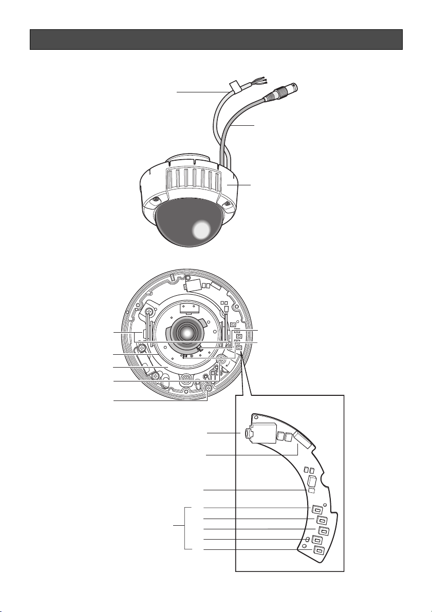
Major Operating Controls and Their Functions
q
w
e
10
y
u
i
o
!0
!4
r
t
!1
!2
!3
!55
!6
!7
!8
!9
Page 11

q Power cable (12 V DC or 24 V AC)
Cautions:
• Supplies 24 V AC or 12 V DC from an
external power source. (WV-CW484F)
• Supplies 220 V to 240 V AC from an
external power source. (WV-CW480S)
w Video output cable with BNC connec-
tor
Connects wih the video connector.
!2 Optional heater connector (6 pin
female)
When an optional heater unit is installed
in the camera, the harness exiting from
the unit will be connected to this.
!3 LED indicator
Shows the ABF status.
!4 Operation buttons
e Enclosure
r Focus lever
Fixes the focus position after adjusting.
t Zoom lever
Fixes the zoom position after adjusting.
y Tilting lock screw
Fixes the tilting position after adjusting.
u Azimuth (Angle adjuster)
Shoots in a straight-angle field of view
when aiming at an object in a slanting
direction even if the tilt angle has been
set.
i Panning table
Adjusts the panning angle of the camera.
o Panning lock screw
Fixes the panning position after adjusting.
!0 Camera lock screw
Fixes the camera and camera attachment.
!5 SET button [(SET), ABF2/MENU]
Activates an item selected in the setup
menu. Refer to p. 17 for details on the
[ABF2] button.
!6 DOWN button [(DOWN), ABF1]
Moves the cursor downward and selects
items in the setup menu. Refer to p. 21
for details on the [ABF1] function.
!7 UP button (UP)
Moves the cursor upward and selects
items in the setup menu.
!8 LEFT button [(LEFT), NEAR]
Moves the cursor to the left, selects the
mode and adjusts some levels.
!9 RIGHT button [(RIGHT), FAR]
Moves the cursor to the right, selects the
mode and adjusts some levels.
!1 Monitor output jack (3.5 diam. mini
jack)
Connects the LCD monitor and such
devices with 3.5 diam. 2-pole L-type plug
for checking images.
11
Page 12

Installations
• The following installation should be made by qualified service personnel or system
installers.
• Mounting Bracket (WV-Q114) is optional for WV-CW484F.
Use the screws provided to the Mounting Bracket.
• Mounting Bracket is provided to WV-CW480S.
Use the screws (M4 x 8, 4 pcs.) provided to this product.
Important:
• Prepare four fixing screws to be used to mount the provided camera attachment according
to the material of the area where the attachment is to be installed.
Recommended tightening torque is as follows.
M4: 1.6 N·m
• Do not use wood screws to fix the camera attachment since they are not strong enough to
support the weight of the camera and the bracket.
• When using the provided camera attachment, make sure that the drain slits do not face
upward.
• When the installation area is not strong enough, reinforce and strengthen it or use Mounting
Bracket or Ceiling Mount Bracket.
• Required pull-out capacity of a single screw/bolt is 196 N or more.
• When using an optional mounting bracket, refer to the operating instructions of the bracket
in use.
The mounting requirements are shown as follows.
Mounting
place
Ceiling/wall
Ceiling/wall
Ceiling
* Make sure that the installed mount bracket can support more than 5 times of the weight of
the camera.
Model
(direct mounting)
WV-Q114 (approx.
470 g)
WV-Q166 (approx.
680 g)
Recommended
screw
M4 or equivalent
–
–
Number of
screws
4 pcs.
–
–
Minimum pull-out
strength (per 1 pc.)
196 N
*
*
12
Page 13
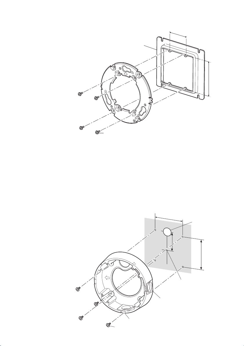
■ Installations (WV-CW484F)
TOP
● Using a Junction Box
Secure the provided camera attachment to
the two gang junction box built in a wall or
Junction box
<Mounting hole pattern>
46 mm
ceiling.
83.5 mm
Camera attachment (provided)
Screws for the camera attachment (Locally procured)
● Using Mounting Bracket WV-Q114 (Option)
• Secure the optional camera mounting bracket to wall or ceiling, and fix the provided camera attachment to the mounting bracket with the screws for the mounting bracket. (Refer to
the following figures.)
Verify the camera attachment and mounting bracket are mounted firmly after screwing
them.
• When routing cables sideway or through
the wall/ceiling, the mounting bracket is
used.
• When routing cables sideway, open the
sideway cable exit unscrewing the lid by
use of a hexagon wrench. Screw the
detached lid to the cable access hole on
the bottom of the bracket.
• Make sure that either of the arrow marks
faces upward.
Mounting
bracket
TOP
TOP
<Mounting hole pattern>
85 mm
Cable access hole
51 mm
85 mm
Bracket centre
Sideway cable exit
* For wall mounting, do not face
the sideway cable exits upward.
Drain slit*
Screws for the mounting bracket
13
Page 14
TOP
<Fixing the camera attachment to the
mounting bracket>
Mounting
bracket
TOP
Camera attachment (provided)
TOP
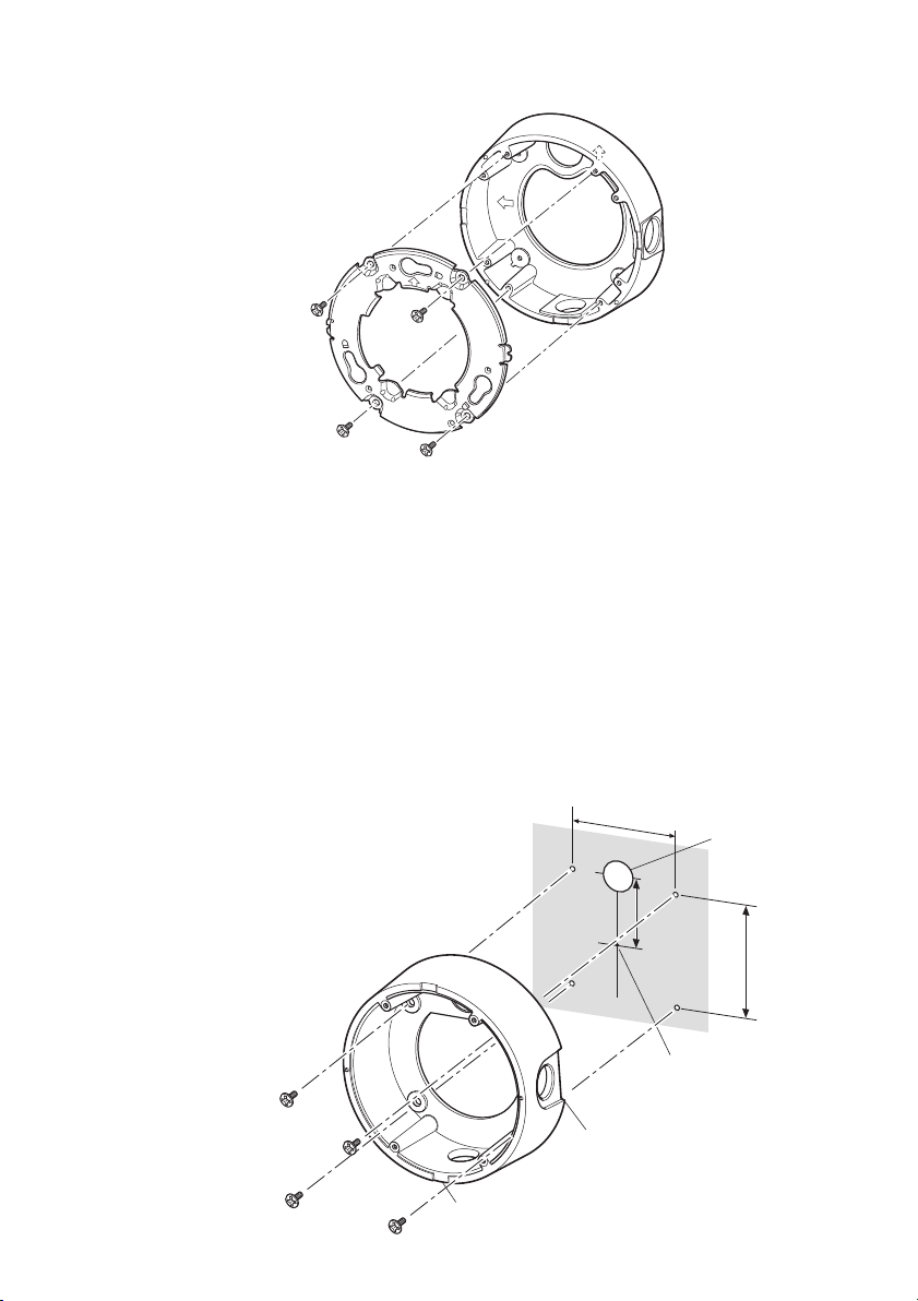
■ Installations (WV-CW480S)
● Using Provided Mounting Bracket
• Secure the provided camera mounting bracket to wall or ceiling, and fix the provided camera attachment to the mounting bracket with the screws for to the mounting bracket. (Refer
to the following figures.)
Verify the camera attachment and mounting bracket are mounted firmly after screwing
them.
• When routing cables sideway or through
the wall/ceiling, the mounting bracket is
used.
• When routing cables sideway, open the
sideway cable exit unscrewing the lid by
use of a hexagon wrench. Screw the
detached lid to the cable access hole on
the bottom of the bracket.
• Make sure that the sideway cable exits
do not face upward.
<Mounting hole pattern>
92 mm
Cable access hole
51 mm
77 mm
14
Drain slit*
Bracket centre
Sideway cable exit
* For wall mounting, do not face the
sideway cable exits upward.
Page 15
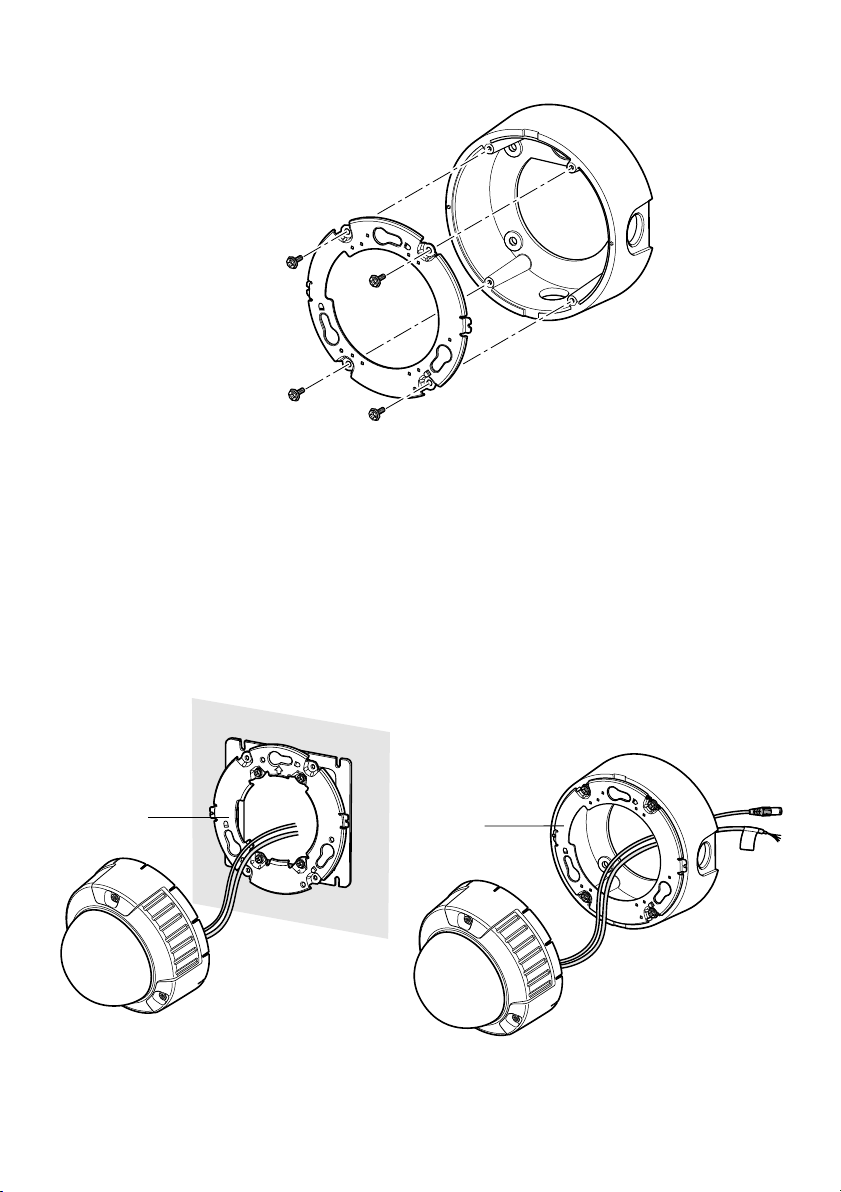
Camera attachment (provided)
<Fixing the camera attachment to the
mounting bracket>
■ How to mount the camera (WV-CW484F, WV-CW480S)
1. Connect the power cable and the BNC plug of the video output cable. (Refer to p. 22
Connections.)
2. Secure the camera with four attachment fixing screws.
<WV-CW484F>
Dent
<WV-CW480S>
Dent
15
Page 16

3. Hook the rear screws on the screw holes
of camera attachment, and turn the camera unit clockwise to fix the camera unit
and camera attachment.
4. Remove the enclosure from the main
body by loosening the three fixing
screws.
The enclosure is fixed with tamperproof
screws.
Loosen the three fixing screws by using
the provided bit for tamperproof screw.
Note: Perform the same procedure when
replacing with the optional dome
cover WV-CW4S.
Protrusion
Screw hole of
camera attachment
Rear screw
5. Remove the screw for transport protection with a Phillips screw driver.
16
Page 17

6. Secure the camera unit to the bracket
with the camera lock screw.
7. Adjust the camera. (Refer to p. 20.)
8. Attach the enclosure to the camera.
Firmly tighten the three tamper-proof
screws.
(Recommended tightening torque:
0.78 N·m)
Camera fixing screw
Notes:
• Defocus may be caused by the reinstalled enclosure. When using a system controller,
adjust the back-focus on the setup menu after attaching the enclosure.
• When not using a system controller, back-focus adjustment is available by using the
[ABF2] button after attaching the enclosure.
q Press the [ABF2] button. The LED indicator will start blinking.
w While the LED indicator is blinking (for around 3 minutes), attach the enclosure to the
camera.
e When the LED indicator changes to steady light, back-focus will be adjusted automati-
cally.
r After the back-focus is adjusted, the LED indicator will go out.
• Do not aim the camera to objects continuously moving.
• If the LED indicator blinks again after changing to steady light, back-focus adjustment
may have failed. In this case, check the back-focus on the LCD monitor. To adjust the
back-focus again, perform Step q to e again.
17
Page 18

■ Waterproof Process
• When routing cables sideway using Mounting Bracket or installing the camera under
eaves, apply waterproof process to the cable and relevant portions.
• The cables are not waterproofed. Provide water sealing for the tube ends and the portions
between cable cores as well as connecting portions.
• The use of vinyl tape or other tapes instead of the butyl tape may cause water absorption
from a gap and finally condensation and water leakage.
● Waterproof processing of cable connection
Surely use the provided butyl tape. (Do not use a sealing material on those parts.)
1. Connect and tape the power cables.
2. Bind the power cables together with the tape.
3. Tape the BNC-BNC joint of video output cable.
Power cable
Video output cable
Winding the provided butyl tape
Stretch the tape to about twice its original length as shown and wind the tape around the
cables. The tape will not harden if the tape is not stretched enough.
18
Stretch the tape to about twice.
Doubled length
Page 19

Notes:
• Surely attach a pipe fitting to the bracket to avoid exposing the cables. Otherwise, cable
deterioration resulting from cable exposure may cause a short circuit.
• Run the conduit downward or pull the conduit out of the side of the bracket. When pulling
the conduit out of the side of the bracket, run the conduit downward once, and upward.
Downward
• For wall installation, face the drain slit downward and do not block the hole. When rain
water is accumulated in the bracket, the water blocks the desiccant agent and air membrane permeation on the rear of the camera, which may cause water leakage.
Drain slit
Pipe
19
Page 20

WIDE
NEAR
Image Adjustment
You can manually adjust the pan/tilt/azimuth
angles, focus, and zoom while observing the
connected monitor.
Notes:
• When connecting an LCD monitor to
adjust the camera images, use an L-type
mini plug. Straight type plugs are not
available.
• Do not hold the camera by lens unit to
adjust panning, tilting, or azimuth.
• The video output to the BNC will be interrupted while an LCD monitor is connected to the monitor output jack.
• While an LCD monitor is connected to
the monitor output jack, ELC (Electric
Light Control) becomes effective to
obtain a proper focus. During focus
adjustment, blooming or smear on highlighted objects may be caused.
However, ALC (Automatic Light Control)
is effective during the normal use, and
blooming or smear is reduced.
• Adjust zoom and focus after adjusting
panning and tilting. (Refer to Step 3 and
4.)
Important:
After pan/tilt/azimuth adjustment, firmly tighten the panning lock screw and tilting lock
screw.
(Recommended tightening torque: 0.59 N·m)
Azimuth
75°
(Angle adjuster)
Tilting lock screw
Panning table
L
O
C
K
Monitor output Jack
(3.5 diam. mini jack)
Panning lock screw
3. Zoom
• Unlock the zoom lever.
• Move the lever to adjust the zoom.
• Lock the lever.
1. Connect an LCD monitor to the monitor
output jack.
2. Pan/tilt/azimuth adjustment
• Loosen the three screws locking the pan
and tilt tables.
• Pan and tilt the table to aim the camera
at what you need to watch.
• Turn the azimuth adjuster to obtain a
level image.
• Tighten the three screws after adjusting.
20
4. Focus
• Unlock the focus lever.
• Move the lever to adjust the focus.
• Lock the lever.
Focus lever
FAR
TELE
NEAR
WIDE
WIDE
Zoom lever
NEAR
Page 21

5. Aim the camera at the targeting objects and if applicable adjust the zoom angle.
6. Press the [ABF1] button.
→ The LED indicator will light up, and a bar graph with "I" cursor and INDICATOR (4-digit
number) will be overlaid on the camera picture.
→ Back-focus will be automatically adjusted.
NEAR FAR
.........|..........
INDICATOR 255 FOCUSING
7. If needed, perform manual adjustment using the [LEFT] or [RIGHT] buttons to obtain the
best focus on the targeted object while observing the picture. See the value of INDICATOR
on the monitor. (The larger the value is, the better the picture quality becomes.)
Notes:
• The bar graph will disappear if no operation is performed for around 10 seconds.
• When changing the angular field of view, move the zoom lever and focus lever again for
adjustment.
<Zoom/focus adjustment>
When shooting an object using an AF lens, the first adjusted focus may be out-of-focus
depending on the focal depth of the lens in use. In this case, focus on a darker object with the
aperture open to prevent out-of-focus.
When "ABF" is selected for "BACK-FOCUS" on the SETUP menu (refer to p. 39), the camera
can automatically focus on a subject with the best available conditions even when the illumination changes.
• Under near-infrared light, the focus may be slightly out-of-focus than under visible light.
When the "BACK-FOCUS SETUP" page is displayed and "AUTO" or "PRESET" is selected
for "C/L ↔ B/W" using the operation buttons on the camera, the camera can focus on subjects both under near-infrared light and under visible light. (However, the camera will not
change the focus according to the illumination change when the focus had been adjusted
once.)
<How to use a variable focal lens>
Before adjusting the variable focal lens, reset the flange-back (back focal) length position to
the default position for the CS-mount (by simultaneously pressing the [LEFT] and [RIGHT] buttons for 2 seconds or more, or by simultaneously pressing the [LEFT] and [RIGHT] buttons
after pressing the [SET] button when the cursor is on "MANUAL-ADJ" on the "BACK-FOCUS
SETUP" page.
21
Page 22

Connections
Caution:
ONLY CONNECT THIS TO 24 V AC or 12 V DC CLASS 2 POWER SUPPLY. (WVCW484F)
Power cable
(WV-CW484F:
Approx. 26 cm,
WV-CW480S:
Approx. 183 cm)
BNC connector BNC connector
Video output cable
(WV-CW484F: Approx. 22 cm,
WV-CW480S: Approx. 42 cm)
● Video Output Connection
Connect the video output connector to the
monitor or other system device with the procured coaxial cable. The maximum extensible length is shown in the table.
RG-11/U
Type of coaxial
cable
Recommended
maximum
cable length
m
RG-59/U
(3C-2V
)
RG-6/U
(5C-2V)
(7C-2V)
600500250
RG-15/U
(10C-2V)
800
● Power Connection
Precaution:
The following connections should be
made by qualified service personnel or
system installers in accordance with
local electrical code.
Brown (Live)
Blue (Neutral)
Green/Yellow (GND)
* When using 12 V DC power supply, the
optional heater unit is unavailable.
• To 24 V AC or 12 V DC power
supply (WV-CW484F)
• To 220 V to 240 V AC power
supply (WV-CW480S)
To GND
BNC connector
To VIDEO IN
• Wire Colours & Functions
Camera power cable
<WV-CW484F>
Wire Colour 24 V AC 12 V DC
Brown 24 V AC (L) Positive
Blue 24 V AC (N) Negative
Green/Yellow To GND
<WV-CW480S>
Wire Colour 220 V to 240 V AC
Brown 220 V to 240 V AC (L)
Blue 220 V to 240 V AC (N)
Green/Yellow To GND
22
Page 23

Cautions:
• Be sure to connect the GND (grounding)
lead of the camera and grounding terminal of the power supply when using a
24 V AC (WV-CW484F) or 220 V to 240 V
AC (WV-CW480S) power source.
• Shrinking the cable-entry seal is a onetime procedure. Do not shrink the cable
entry seal until it has been ascertained
that unit is functioning.
ONLY CONNECT THIS TO 24 V AC or
12 V DC CLASS 2 POWER SUPPLY.
(WV-CW484F)
• To prevent fire or electric shock hazard,
the UL listed wire VW-1 style 1007 should
be used for the cable for Input Terminals.
• Do not use a transformer larger than
10 VA.
• Cable Length and Wire Gauge
<WV-CW484F>
24 V AC
The recommended cable length and thickness are shown in the table for reference.
The voltage supplied to the power terminals
of the camera should be within 19.5 V AC
and 28 V AC.
12 V DC
Use the formula below to calculate the power
cable and power supply. The voltage supplied to the power terminals of the camera
should be within 10.5 V DC and 16 V DC.
Resistance of copper wire [at 20 °C]
Copper wire
size (AWG)
Resistance
Ω/m
10.5 V DC ≤ V
#24
(0.22 mm2)
0.078
#22
(0.33 mm2)
0.050
A - 2(R x I x L) ≤ 16 V DC
#20
(0.52 mm2)
0.03
#18
(0.83 mm2)
0.018
L : Cable length (m)
R : Resistance of copper wire (Ω/m)
V
A : DC output voltage of power supply
unit
I : DC current consumption (A). See
specifications.
Important: When using 12 V DC power sup-
ply, the optional heater unit is unavailable.
Recommended wire gauge for 24 V AC line.
Copper wire
size (AWG)
Length of
Cable
(Approx.)
(m)
#24
(0.22 mm
20
2
)
(0.33 mm2)
#22
30
#20
(0.52 mm2)
45
#18
(0.83 mm2)
75
23
Page 24

Heater unit screw
Optional heater
connector
■ Optional Heater Unit WV-CW4H
● Introduction
Installing this heater unit enables the camera to operate in a low-temperature environment
below –30 °C. The heater turns on automatically when the temperature inside the camera drops
below +10 °C and turns off when the temperature rises.
A small fan inside the unit will minimize condensation on the surface of the enclosure caused
by changes in ambient temperature unless temperatures change too rapidly. The fan will stop
when there is no possibility of condensation.
Cautions:
• When using 12 V DC power supply, the optional heater unit is unavailable.
• Turning the heater on and off may disturb the camera images.
• When servicing, pay attention to high temperature on the surface of the heater unit.
Disconnect the harness and wait until the heater unit cools.
• When you install and operate the camera in a low-temperature environment below –10 °C, it
may take time (around 30 minutes) for the inside of the camera to warm up. In such a case,
wait around 30 minutes or more.
● Installation
1. Open the enclosure.
2. Place the heater unit in the camera and fix it with the supplied screw (x1).
3. Insert the harness (x1) into the heater unit connector of the camera.
Note: Attach the desiccant pack so that it does not block ventilation holes or hang over the
top of the wall.
4. Attach the enclosure.
Important: After mounting the heater unit, arrange the harness cable so as not to be tangled
around the enclosure and equipment inside the camera.
24
Page 25

About Setup Menus
Before operation, setup of this camera is required. On the setup menu, you can check current
settings and perform settings to meet requirements.
The following is an example of setup procedure when LANGUAGE is set to ENGLISH.
Settings items of the camera setup page
Setup item Description
CAMERA Configure the settings relating to camera operations
CAMERA ID The camera title can be edited and displayed on the
screen.
ALC Configure the light control method.
SHUTTER Select the shutter speed.
AGC Select the method of the gain adjustment.
SENS UP Adjust the sensitivity.
SYNC Configure the method of the synchronization.
WHITE BAL Select the method of the white balance adjustment.
MOTION DET Configure the settings for the motion detection func-
tion.
DNR Configure the settings for the DNR (Digital Noise
Reduction) function.
RESOLUTION Select a horizontal resolution mode.
BW MODE Configure the settings relating to the BW mode such
as the settings for switching between the colour mode
and the BW mode.
PRIVACY ZONE It is possible to mask a designated zone and as a pri-
vacy zone.
EL-ZOOM Adjust the electronic zoom.
UPSIDE-DOWN Select the upside down positioning of camera picture.
STABILIZER Select "ON" or "OFF" to determine whether or not to
use the image stabilizer to prevent shaky images.
LENS Adjust the focus position automatically.
BACK-FOCUS Select the method of the flange-back (back focal)
length adjustment and adjust the flange-back (back
focal) length minutely.
Reference
pages
29
30
31
32
32
33
33
34
36
36
36
37
38
38
38
39
39
25
Page 26

Setup item Description
SPECIAL
CHROMA GAIN Adjust the chroma level (colour density).
AP GAIN Adjust the aperture level.
PEDESTAL Adjust the pedestal level (brightness).
PIX OFF Correct image defects such as scratches.
CAMERA RESET Reset the settings of setup menu to the default set-
tings.
SER.NO. Check the serial number of this camera.
LANGUAGE Select the language to display the setup menu.
Reference
pages
40
41
41
41
42
42
29
26
Page 27

■ Basic operation
The following are descriptions of how to configure each setup item using the operation buttons
(refer to p. 10) on the camera. Setup using an optional system controller is also available.
Notes:
• The illustrations are the examples to be displayed on a video monitor.
1. Hold down the [SET] button for around 2 seconds.
→ The top page will be displayed.
2. Move the cursor onto "END" by press the
[UP] or [DOWN] button.
3. Press the [SET] button after moving the cursor onto "SETUP" by pressing the [RIGHT]
button.
→ The "DISABLE" indication will change into
"ENABLE" and the settings will become
editable.
4. Move the cursor onto the desired setup item
and press the [SET] button.
→ The setup page of the selected setup item
will be displayed.
5. Configure the settings for each item.
Select setup item: Move the cursor by
pressing the [UP] or [DOWN] button.
Change the parameter: Press the [LEFT] or
[RIGHT] button.
Display the detailed settings page of the
setup item: Press the [SET] button when
the setup item with the [O] mark is
selected.
Go back to the previous page: Move the
cursor onto "RET" and press the [SET]
button.
Go back to the top page: Move the cursor
onto "TOP" and press the [SET] button.
MODEL WV-CW480 SERIES
CAMERA
BACK-FOCUS
SPECIAL
LANGUAGE
END SETUP DISABLE
MODEL WV-CW480 SERIES
CAMERA
BACK-FOCUS
SPECIAL
LANGUAGE
END SETUP ENABLE
**CAMERA SETUP** 1/2
CAMERA ID OFF
ALC ALC
SHUTTER OFF
AGC ON(HIGH)
SENS UP OFF
SYNC INT
WHITE BAL ATW1
MOTION DET OFF
DNR HIGH
RESOLUTION HIGH
BW MODE
**CAMERA SETUP** 2/2
PRIVACY ZONE OFF
EL-ZOOM OFF
UPSIDE-DOWN OFF
STABILIZER OFF
LENS PANASONIC
RET TOP END
27
Page 28

6. To exit from the SETUP menu and display images from the camera, move the cursor onto
"END" and press the [SET] button.
Notes:
• To prevent erroneous operations, the "DISABLE" indication will always be displayed when
the top page is displayed from the camera. To operate the SETUP menu, switch the "DISABLE" indication to the "ENABLE" indication first.
• The cursor position will be displayed highlighted.
28
Page 29

Setting Procedures
First, select a language for menu display and camera ID display.
Language Setup (LANGUAGE
SETUP)
**LANGUAGE SETUP**
LANGUAGE ENGLISH
1. Select LANGUAGE on the top menu and
press the [SET] button.
→ The LANGUAGE SETUP menu opens.
2. Select a language. The default setting is
English.
SET
RET TOP END
Available languages: ENGLISH, FRANÇAIS,
ESPAÑOL, DEUTSCH, ITALIANO, кмллдав, CHINESE, JAPANESE
3. Select SET on the menu and press the [SET] button.
1. Camera Identification Setting (CAMERA ID)
Assign a name to the camera using up to 16 characters to display it overlaying on the camera
picture in the selected position.
Note: If you change the language selection after
the assignment of camera ID, it will be
erased.
1. On the CAMERA SETUP menu, select ON↓ or
OFF↓ for CAMERA ID and press the [SET]
button.
ON↓: Displays entered camera ID.
OFF↓: Does not display the ID.
→ The CAMERA ID menu opens.
2. Select a character from the character area
and press the [SET] button.
→ The selected characters are displayed in
the editing area.
3. Repeat these procedures until all characters
are entered.
• To enter a blank space, select SPACE and
press the [SET] button.
• To replace a specific character in the editing
area:
1. Move the cursor to the editing area and
then move the pointer to the character to
be replaced pressing the [LEFT] and
[RIGHT] buttons.
2. Move the cursor to a candidate character
in the character area and press the [SET]
button.
**CAMERA SETUP** 1/2
CAMERA ID OFF
ALC ALC
SHUTTER OFF
AGC ON(HIGH)
SENS UP OFF
SYNC INT
WHITE BAL ATW1
MOTION DET OFF
DNR HIGH
RESOLUTION HIGH
BW MODE
CAMERA ID
0123456789
ABCDEFGHIJKLM
NOPQRSTUVWXYZ
().,'":;&#!?=
+-*/%$
SPACE POSI
RET TOP END RESET
................
↵
FLOOR 1
↵↵
↵
Character
Cursor
Character
Area
Command
Editing
Area
Pointer
Highlighted
29
Page 30

• To erase all characters of the camera ID, select RESET and press the [SET] button.
Note: For Chinese language, up to 8 characters can be entered.
4. To specify the ID display position:
1. Select POSI and press the [SET] button.
→ The entered camera ID will be highlighted on the screen.
2. Move it into the appropriate position and press the [SET] button.
→ The position is determined and the screen will return to the CAMERA ID menu.
Note: Keep pressing any of [LEFT], [RIGHT], [UP], or [DOWN] button for a second or
more to move the camera ID faster as necessary.
2. Light Control Mode Setting (ALC)
Select a light control mode depending on the lens type mounted.
ALC↓: Is applicable to the auto iris lens. SUPER-D3 is available with this selection.
2-1. ALC Mode with SUPER-D3 ON
Super Dynamic 3 Function (SUPER-D3)
In the SUPER-D3 mode, more photometric weight is given to the centre of the screen than to
the edge where a bright backlight would most likely be located.
SUPER-D3 ON SUPER-D3 OFF
Nighttime
Daytime
Nighttime
Daytime
SUPER-D3 ON: Enables SUPER-D3 to compensate backlight automatically.
SUPER-D3 OFF: Enables manual setting to compensate backlight.
Notes:
• When set to ON, the available parameters for SHUTTER and SENS UP will be limited as
shown on the next page.
• Set SUPER-D3 to OFF when noise in a bright portion, flickerings, or colour deterioration are
observed.
1. Move the cursor to ALC and press the [SET] button.
→ The ALC CONT menu opens.
2. Select ON for SUPER-D3.
3. Adjust the video output level (LEVEL) by
moving the "I" cursor. It may be better to
adjust LEVEL slightly higher.
**ALC CONT**
BACK LIGHT COMP
SUPER-D3 ON
LEVEL ..I...128
- +
RET TOP END
30
Page 31

2-2. ALC Mode with SUPER-D3 OFF
1. Move the cursor to ALC on the CAMERA
SETUP menu and select OFF for SUPER-D3
on the ALC CONT menu.
→ MASK SET↓ appears on the ALC CONT
menu.
2. Select MASK SET and press the [SET] but-
ton.
→ The 48 mask areas appear overlaid on the
camera picture with the blinking cursor in
the upper left corner.
3. Move the cursor to an area where the back-
light is bright and press the [SET] button to
mask the area.
→ The masked area appears alternately
white and blinking when the cursor is on
the area, or it turns white when the cursor
is on other areas.
4. To cancel masking, move the cursor to a
masked area and press the [SET] button.
→ When masking of the area is cancelled, it
changes from white to normal.
To cancel all the masking, press the
[LEFT] and [RIGHT] buttons simultaneously for 2 seconds or more.
**ALC CONT**
BACK LIGHT COMP
SUPER-D3 OFF
MASK SET
LEVEL ..I...128
- +
RET TOP END
Blinking
White
Blinking
↵
5. Repeat step 3 and 4 as necessary.
6. Press the [SET] button for 2 seconds or more.
→ The ALC CONT menu appears.
7. Adjust the video output level (LEVEL) by moving "I" cursor.
Note: If ON is selected for SUPER-D3, a shadow (black line) may appear at the boundary
between the bright and the dim portions. This is a natural phenomenon and does not
indicate trouble.
3. Shutter Speed Setting (SHUTTER)
Select a proper shutter speed when ALC is selected on the CAMERA SETUP menu. Selecting a
faster speed will reduce blurring when objects quickly move. The default setting is OFF.
SUPER-D3 OFF:
OFF (1/50) 1/120
1/10000 1/4000 1/2000 1/1000
1/250 1/500
31
Page 32

Notes:
• Only OFF is available when SUPER-D3 is set to ON.
• When a faster speed is selected for the electronic shutter, the picture will generally become
darker, and sometimes a smear (vertical stripes caused by bright objects) may appear.
4. Gain Control Setting (AGC)
Select an automatic gain control mode. This setting raises the gain and brightens the image
under low light conditions. The default setting is ON (HIGH).
Available modes: ON (HIGH / high), ON (MID / medium), ON (LOW / low), OFF
5. Electronic Sensitivity Enhancement (SENS UP)
Select a proper enhancement rate when the camera is set to ALC mode. The higher rate you
select, the brighter the picture will be. The default setting is OFF.
AUTO: Sets AGC to ON and adaptively raises the sensitivity up to the selected amplification
rate, for example 10 times when set to X10 AUTO.
FIX: Raises the sensitivity fixedly to the selected rate.
OFF: Does not raise the sensitivity.
OFF
SUPER-D3 OFF:
SUPER-D3 ON:
* The factory default
Notes:
• Some types of system controllers may not operate some of the SENS UP functions. If this
happens, use the operation buttons on the camera.
• When you select AUTO for SENS UP and ON for SUPER-D3, the SENS UP function has priority so that the SUPER-D3 function is not activated automatically.
• While the SENS UP function is selected, noise, spots or a whitish phenomenon may appear
in the picture when the sensitivity of the camera is increased. This is a normal phenomenon.
• Only when OFF, X2 FIX, or X2 AUTO is selected for sensitivity enhancement (SENS UP), It
is possible to perform ABF adjustment or to select AUTO for C/L ↔ B/W on the BACKFOCUS SETUP menu. When a sensitivity rate other than X2 FIX or X2 AUTO is selected,
use PRESET and FIX for C/L ↔ B/W on the BACK-FOCUS SETUP menu.
X2 AUTO
X32 FIX X10 FIX X6 FIX X4 FIX X2 FIX
OFF*
X16 FIX
X2 AUTO
X4 AUTO X6 AUTO X10 AUTO
X4 AUTO X6 AUTO X10 AUTO
OFF
32
Page 33

6. Synchronization Setting (SYNC)
1. Select a sync mode.
VD2: Multiplexed vertical drive, highest priority
LL: Line-Lock, follows the phase of supplied AC power, 2nd priority
INT: Internal sync, lowest priority
Notes:
• Selection is not available when VD2 is added to the camera. Selection from LL is available when the respective sync is added.
• When LL is selected, phase adjustment is required.
2. Line-Lock Vertical Phase Adjustment (V PHASE)
• Select LL and press the [SET] button.
• Prepare a dual-trace oscilloscope and supply
it with the video output of the camera to be
adjusted and that of the reference camera.
• Set the oscilloscope to the vertical rate and
expand the V-sync portion.
• Select a proper COARSE phase from 16
steps (22.5 degrees/step) that makes the two
video signals on the oscilloscope the closest.
• Select a proper FINE phase so that the two
video signals on the oscilloscope come as
close as possible.
Notes:
• Moving the "I" cursor across the +/- end will shift the FINE range.
• Press the [LEFT] and [RIGHT] buttons simultaneously to reset the V PHASE to the
default (0 degree).
• Keep pressing the [LEFT] and [RIGHT] buttons for a second to move the "I" cursor
faster if necessary.
• Spike noise if contained in the AC mains may disturb synchronization of LL.
**SYNC**
V PHASE
COARSE 1(1--16)
FINE ...I...128
- +
RET TOP END
7. White Balance Setting (WHITE BAL)
Select a mode for WHITE BAL on the CAMERA SETUP menu. The default setting is ATW1.
ATW1: Is automatically adaptable to the colour temperatures of 2 700K - 6 000K.
ATW2: Is automatically adaptable to the use of sodium lamps (2 000K - 6 000K).
AWC: Is automatically adaptable to the colour temperatures of 2 000K - 10 000K.
Notes:
• When ATW1 or ATW2 is selected, no further operation is required.
• ATW1 and ATW2 do not appear on the setup menu of the system controller.
• Select AWC in the following cases: the colour temperature is out of the 2 000K - 6 000K
range, the scene contains mostly high colour temperatures such as blue sky or sunset, or
the scene is dim.
• When AWC is selected, the AWC setting is required.
33
Page 34

AWC Setting
1. Select AWC and press the [LEFT] button.
→ AWC will change to AWC → PUSH SW.
2. Press the [SET] button.
→ PUSH SW will be highlighted while the AWC setting is performed.
Note: If the white balance is not set, PUSH SW is being highlighted.
3 . Press the [RIGHT] button.
Manual Fine Adjustment
Perform fine adjustment as necessary.
1. Select WHITE BAL and press the [SET] button.
→ Fine adjustment menu of ATW or AWC will
open.
2. Adjust finely R (Red) and B (Blue) gain by
moving the "I" cursor.
**ATW1**
R ...I...128
- +
B ...I...128
- +
RET TOP END
8. Motion Detection Setting (MOTION DET)
When a series of changes in pictures is detected, the camera outputs an alarm to the external
device such as a disk recorder. The recorder will start recording the pictures.
1. Select a mode for MOTION DET on the CAMERA SETUP menu.
The default setting is OFF.
OFF: Disables the alarm output.
MODE1: Outputs alarm when a series of
motions is detected.
MODE2: Outputs alarm when a series of
scene changes is detected.
→ The MODE1 menu opens when you select
MODE1 and press the [SET] button.
2. Adjust for LEVEL to optimize the sensitivity of
detection.
** MODE1 **
LEVEL ...I..128
- +
DWELL TIME 2S
DISPLAY MODE
ALARM OFF
MASK SET
RET TOP END
↵
↵
3. Select a dwell time. The default setting is 2S.
Available time (second): 2, 5, 10, 30
The next detection will be performed after
the set time elapses.
4. Select MASK SET and press the [SET] button.
→ A 48-split screen opens.
• Specify non-detection (mask) and detection areas in the same way as described earlier in
2-2 ALC Mode.
• Hold down the [SET] button for 2 seconds to return to the MODE1 menu.
Note: Perform the setting of mask area after STABILIZER in the CAMERA SETUP menu is
set to OFF.
34
Page 35

5. Select ON or OFF for ALARM under DISPLAY MODE.
ON: Outputs an alarm
OFF: Does not output an alarm. This is applicable any of the following controllers are used:
WV-RM70, WV-CU550 series, WV-CU161, WV-CU360, WV-CU650, WV-CU850, WVCU950
6. Select DISPLAY MODE and press the [SET] button to see the current settings.
When a motion is detected, the area will blink.
• Press the [SET] button to return to the MODE1 menu.
7. As necessary, repeat to perform LEVEL adjustment and MASK setting by checking on the
DISPLAY MODE screen.
Notes:
• In systems other than Panasonic, select OFF for MOTION DET to prevent system
devices from confusing time-code signal with alarm signal.
• Set MASK SET over the areas where leaves or curtains etc. are swaying.
• Adjust the detection level to prevent detection from confusing motion with noise under
low light conditions.
• It takes around 0.2 seconds for the alarm signal to reach the VTR’s alarm terminal after
detection.
• The motion/scene change detection is not specifically intended to prevent theft or fire.
Motion Detector
The motion detector divides the screen into 48 blocks and monitors changes in the luminance in each block. When it detects any change (movement) in the image, it outputs an
alarm signal. When a change (movement) in the image is detected while in the auto
mode, the alarm signal is output and the camera stops at the preset position for a specified amount of time.
Demo Mode
The demo mode divides the screen into 48 blocks and monitors changes in the luminance in each block. It also masks any part of the picture where there is a change in
average luminance that exceeds the currently specified detection sensitivity level. The
demo mode results can be used to determine the optimum detection sensitivity level
(step 5) and the areas of the screen that need to be masked (step 1).
35
Page 36

About MODE2 of Motion Detection
• The camera will detect a scene change in the following cases.
When the lens is fully sprayed or covered with a cloth, lid, or the like
When the camera direction is suddenly changed
• The camera will not detect a scene change in the following cases.
When a cloth with patterns covers the lens and it sways in the wind
When some portions in the screen are not veiled
When the screens are similar in scene patterns although the camera direction has
changed
• The camera will faultily detect a scene change in the following cases.
When an obvious brightness change arises (ex. On/Off of the lamps)
When objects move continuously such as traffic in busy streets
9. Digital Noise Reduction Setting (DNR)
Select a DNR mode suitable to the camera site conditions. The default setting is HIGH.
HIGH: Greatly reduces noise, though it produces afterimages when objects move.
LOW: Slightly reduces noise, and produces less afterimages.
10. Resolution Setting (RESOLUTION)
Select a horizontal resolution mode. The default setting is HIGH.
NORMAL: Resolves more than 480 TV lines.
HIGH: Resolves typically 540 TV lines, though noise may increase when SENSE UP is activated
in low lighting conditions.
11. Black and White Mode Setting (BW MODE)
1. Select BW MODE on the CAMERA SETUP menu and press the [SET] button.
→ The BW MODE menu opens.
2. Select a mode for BW. The default setting is OFF.
AUTO1: Sets the mode to black-and-white if the picture is dark or to colour if the picture is
bright enough.
AUTO2: Functions the same as AUTO1, except this is applied to the use near infrared light.
(wavelength ≥ 800 nm).
ON: Sets the mode to black-and-white.
OFF: Sets the mode to colour.
Notes:
• There may be cases where AUTO1 or AUTO2 does not function well if the camera is
aimed at subjects continuously moving or a scene filled with a single colour such as a
blue sky.
• It is possible to set up the back-focus mode to compensate for defocus liable to happen when the camera automatically switches between the colour and black-and-white
modes. Refer to p. 39. Back-focus Setting for details.
36
Page 37

→ When AUTO1 or AUTO2 is selected, LEVEL and DURATION TIME appear.
3. Select a threshold LEVEL to switch between
the colour and black-and-white mode. The
default setting is HIGH.
HIGH: Switches the mode at approx. 5 lx illu-
mination.
LOW: Switches the mode at approx. 1 lx illu-
**BW MODE**
BW AUTO1
LEVEL HIGH
DURATION TIME .I..
S L
BURST(BW) ON
mination.
4. Select a duration time to determine whether
RET TOP END
to switch the mode. The default setting is 30 seconds.
Available time: (Short) 10 s ↔ 30 s ↔ 60 s ↔ 300 s (Long)
5. Select a burst signal mode. The default setting is ON.
ON: Supplies the (colour) burst signal with black-and-white composite video.
OFF: Supplies no burst signal.
Note: Using ON is usually recommended. Try both ON and OFF to match to connected
devices (recorders, monitors, etc.) that have different characteristics.
12. Privacy Zone Setting (PRIVACY ZONE)
Perform settings of up to eight privacy zones where you wish to veil the monitor screen.
1. Select ON(1), ON(2) or OFF for PRIVACY ZONE on page 2 of the CAMERA SETUP menu
and press the [SET] button. The default setting is OFF.
ON (1): Veils the zone with grey.
ON (2): Veils the zone with mosaic.
OFF: Displays pictures normally.
→ The ZONE NUMBER selection menu
opens.
**ZONE NUMBER 1/8**
2. Select a zone number on the top line using
the [LEFT] and [RIGHT] buttons and press
the [SET] button. The zone number followed
by an asterisk * indicates that it has been
already registered.
→ POSITION, SCALE, and a frame appear
on the menu.
3. Select →PUSH SW for POSITION and press
the [SET] button.
→ Position selection becomes available.
4. Move the picture portion to be veiled to the
centre of the frame using the [LEFT],
[RIGHT], [UP], or [DOWN] button.
RET TOP END
**ZONE NUMBER 1/8**
POSITION
SCALE
SET DEL
RET TOP END
→
PUSH SW
→
PUSH SW
37
Page 38

5. Select →PUSH SW for SCALE and press the [SET] button.
→ Zone scale adjustment becomes available.
6. Adjust the zone scale using the [LEFT], [RIGHT], [UP], or [DOWN] button.
7. To apply the settings, move the cursor to SET and press the [SET] button.
→ The screen returns to the ZONE NUMBER selection menu.
To delete the settings, select DEL and press the [SET] button.
13. Electronic Zoom (EL-ZOOM)
1. Move the cursor to EL-ZOOM.
2. Select ON or OFF by pressing [LEFT] and
[RIGHT] buttons.
The default setting is OFF.
ON: x2 electronic zoom is available with the
ZOOM switch on the controller.
OFF: The electronic zoom function is dis-
abled.
3. While the cursor is on EL-ZOOM, press the
[SET] button. The EL-ZOOM menu appears.
4. Move the cursor to PUSH SW for ZOOM and
press the [SET] button to display the ZOOM
setting menu.
5. Press the [UP] or [DOWN] button to zoom in
or out the image.
6. Move the cursor to PUSH SW for PAN/TILT
and press the [SET] button. The PAN/TILT
setting menu appears.
7. Press [LEFT], [RIGHT], [UP], or [DOWN] button to change the angular field of view.
8. To return to the EL-ZOOM menu, press the [SET] button.
**EL-ZOOM**
PAN/TILT →PUSH SW
ZOOM →PUSH SW
U TILT D/L PAN R
RET TOP END
**EL-ZOOM**
PAN/TILT →PUSH SW
ZOOM →PUSH SW
U ZOOM D
RET TOP END
14. Camera Picture Upside Down Positioning (UPSIDE-DOWN)
1. Move the cursor to UPSIDE-DOWN.
2. Select ON when you want to turn the picture upside down.
15. Auto Image Stabilizer (STABILIZER)
This function electronically compensates for an unstable camera image due to movement of a
mounting pole or bracket. The default setting is OFF.
ON: Automatically compensates for an unstable image.
OFF: Image stabilizer will not operate.
Notes:
• When set to ON, some effective pixels on the edge of the CCD are used by the stabilization
function. This may result in a small reduction in resolution and a narrower angle of view.
After activating the image stabilizer function, check that the field of view is correct.
38
Page 39

• Image stabilization may not function where there is excessive camera movement or when
**BACK-FOCUS SETUP**
ABF
→
PUSH SW
MANUAL-ADJ
C/L
← →
B/W AUTO
SETUP-SW LOCK OFF
NEAR FAR
.........I.........
INDICATOR XXXX
RET TOP END
↵
the scene is low light or low contrast objects.
16. LENS
Select PANASONIC.
17. Back-focus Setting (BACK-FOCUS SETUP)
Perform adjustment of the back-focus (flangeback: the gap between the lens and focal plane)
remotely on this menu using a system controller.
After installation, you can perform this adjustment
when defocus arises that may be caused by
long-term use, environmental changes, etc.
Important: Do not use the ABF function for con-
tinuous or repetitive purposes (ex. autofocus
etc.). This function is to be used to correct
defocus caused by switching between colour
and black - and - white when/after installing
the camera.
1. Select BACK-FOCUS on the top menu and press the [SET] button.
→ The BACK-FOCUS SETUP menu opens.
2. Select ABF and press the [SET] button.
→ Adjustment is automatically performed.
Notes:
• Performing ABF will function to obtain the best focus around the centre areas in a
scene.
• Performing ABF is available only when OFF, X2 AUTO, or X2 FIX is selected for SENS
UP.
• Using the ABF function under low light conditions may cause noise.
3. Select MANUAL-ADJ and press the [SET] button if manual adjustment is required.
The manual back-focus adjustment screen will open.
• Use the [LEFT] or [RIGHT] buttons to move the "I" cursor and obtain a proper focus.
→ Refer to the 4-digit number on the second bottom line. The larger the number is, the bet-
ter the focus will be.
• Select RET and press the [SET] button to go back to the menu setup.
39
Page 40

4. Select a mode for C/L ↔ B/W. The default setting is AUTO.
**SPECIAL SETUP**
CHROMA GAIN ...I..128
AP GAIN ...I..128
PEDESTAL ...I..128
– +
PIX OFF
CAMERA RESET
→
PUSH SW
SER.NO. XXXXXXXX
RET TOP END
↵
AUTO: Adjusts the back-focus automatically every time the camera switches the mode
between colour and black-and-white. AUTO is usable only when OFF, X2 AUTO, or X2
FIX is selected for SENS UP.
PRESET: Adjusts the back-focus to the positions for colour mode and black-and-white
mode that are preset by performing step 2 (automatic) or step 3 (manual) under the
respective light conditions.
FIX: Fixes the back-focus after adjustment.
5. Select ON or OFF for SETUP-SW LOCK. The default setting is OFF.
OFF: Enables the [SET] button to open the back-focus adjustment screen while the camera
picture is displayed.
ON: Disables the [SET] button from opening the back-focus adjustment screen.
6. To reset the back-focus to the default setting, press the [LEFT] and [RIGHT] buttons simultaneously.
Notes:
• Select FIX or PRESET and adjust manually the back-focus when automatic adjustment
is hindered by the following conditions.
1. Dirt or a water drip attached to window glass
This causes defocus on the object beyond the glass.
2. Objects in low lighting conditions
3. Objects extremely bright
4. Flat contrast objects such as white wall or fine felt
5. Objects placed on the outskirts of the scene
6. More than one object placed with a certain depth
7. An object having a certain depth
8. Objects continuously moving such as busy streets
9. Objects extremely flickering
10. Objects consisting of parallel horizontal lines such as a window shade
• Matsushita Electric Industrial Co., Ltd shall not be responsible for any inconvenience,
damage or loss caused by or attribute to inappropriate settings for the ABF function.
18. Special Menu (SPECIAL SETUP)
Select SPECIAL on the top menu and press the
[SET] button.
→ The SPECIAL SETUP menu opens.
18-1. Chroma Level Setting (CHROMA
GAIN)
Move the "I" cursor to adjust the chroma level.
40
Page 41

18-2. Aperture Gain Setting (AP GAIN)
Move the "I" cursor to adjust the aperture gain level.
Lower the level when moire (a kind of noise, optical interference) appears on the screen as part
of minute crosshatch pattern, etc.
18-3. Pedestal Level Setting (PEDESTAL)
Move the "I" cursor to adjust the pedestal level (black level).
18-4. Pixel Compensation Setting (PIX OFF)
Perform settings to compensate a maximum of 16 blemish pixels on the pickup device.
1. Select PIX OFF and press the [SET] button.
→ The PIX OFF menu opens with numbers
from 1 to 16.
2. Select a number and press the [SET] button.
→ The PIX OFF assignment screen opens
with a + cursor.
3. Move the cursor to the centre of a blemish
**PIX OFF**
1 2 3 4
5 6 7 8
9 10 11 12
13 14 15 16
000 000
RET TOP END
position until its appearance becomes less
obvious. Finally, press the [SET] button.
→ The horizontal and vertical positions (coor-
dinate) of the blemish will be displayed
with a 6-digit number on the second bottom line.
→ The blemish position is registered to be
compensated.
→ The screen returns to the PIX OFF menu
that displays the number followed by an
asterisk if it has been registered.
4. Repeat above steps as necessary.
5. To cancel a registration, select an asterisked number in the PIX OFF menu and press the
[SET] button.
→ The PIX OFF assignment screen opens.
Hold down the the [LEFT] and [RIGHT] buttons simultaneously for 2 seconds or more.
→ The PIX OFF menu appears displaying the number without an asterisk if its registration
has been cancelled.
41
Page 42

18-5. To reset to the default settings (CAMERA RESET)
1. Select CAMERA RESET.
→ The PUSH SW is highlighted.
2. While holding down the [LEFT] and [RIGHT] buttons, press the [SET] button for 2 seconds
or more.
→ The camera will return to the default settings.
Note: PIX OFF setting cannot be initialized.
18-6. The serial number of the camera will be displayed. (SER. NO.)
42
Page 43

Troubleshooting
Before asking for repairs, check the symptoms with the following table.
Contact your dealer if a problem cannot be solved even after checking and trying the solution
or if the problem is not described below.
Symptom
No image is displayed.
Images are displayed
blurry.
Cause/solution
• Is 24 V AC or 12 V DC power supply connect to the power supply
terminal? (WV-CW484F)
• Is 220 V to 240 V AC power supply connect to the power supply
terminal? (WV-CW480S)
• Is the video output cable connected to the video connector of the
monitor?
→ Confirm the cables are firmly
connected.
• Are the brightness and contrast of
monitor properly adjusted?
→ Confirm the monitor.
• Aren't there dusts or dirt on the
lens?
→ Check if there are dust or dirt
on the lens.
• Is the focus adjusted correctly?
→ Check if the focus is adjusted
correctly.
Reference
pages
22
–
–
20
The power cord insulation
is damaged.
The power cord gets hot
during use.
The power cord gets hot
when bent or stretched.
• The power cord is worn out. This
may result in electric shock or a
fire. Shut off the power, and refer
to qualified service personnel.
–
43
Page 44

Specifications
<WV-CW484F General specifications>
Power source and power
consumption: 24 V AC 50 Hz, 4.1 W (Without heater), 11 W (With heater),
12 V DC 50 Hz, 340 mA (Without heater), 470 mA (With heater)*
Ambient temperature: –10 °C to +50 °C
–30 °C to +50 °C**
Ambient humidity: 90 % or less
Water resistance: IEC60529 (IP66, Against ingress of water with harmful effects
powerful jetting)*** (Camera unit)
Dimensions: ø154 mm (W) x 141.2 mm (H) (excluding connectors/terminals)
Weight: Camera: 1.3 kg
Camera attachment: 100 g
<WV-CW480S General specifications>
Power source and power
consumption: 220 V to 240 V AC 50 Hz, 7 W (Without heater),
13 W (With heater)
Ambient temperature: –10 °C to +50 °C
–30 °C to +50 °C**
Ambient humidity: 90 % or less
Water resistance: IEC60529 (IP66, Against ingress of water with harmful effects
powerful jetting)*** (Camera unit)
Dimensions: ø160 mm (W) x 161.7 mm (H) (excluding connectors/terminals)
Weight: Camera: 1.5 kg
Camera attachment: 80 g
Mounting bracket: 550 g
* Heater Unit WV-CW4H (option) is not available with 12 V DC power supply.
** With Heater Unit WV-CW4H (option)
*** Applicable only when the installation and waterproof process are done properly.
Camera
Image sensor: 1/3 inch interline transfer CCD
Effective pixels: 752 (H) x 582 (V)
Scanning area: 4.8 (H) x 3.6 (V) mm
Scanning system: 2 : 1 interlace scan
Scanning lines: 625 lines
Scanning frequency: Horizontal: 15.625 kHz
Vertical: 50.00 Hz
Resolution: Horizontal: 480 TV lines (C/L Normal), 540 TV lines typ., 520 TV
lines min. (C/L High), 570 TV lines (B/W)
Vertical: 400 TV lines min. (Centre)
Video output: 1.0 V[P-P] PAL composite 75 Ω/BNC connector
Signal-to-noise ratio: 50 dB (Equivalent to AGC Off, weight On)
Dynamic range: 54 dB typ
44
Page 45

Minimum illumination: When using Clear Dome Cover: 0.08 lx at F1.4 (B/W) 0.6 lx at
F1.4 (C/L)
When using Smoke Dome Cover (Option): 0.16 lx at F1.4 (B/W)
1.5 lx at F1.4 (C/L)
Lens mount: CS-mount
Lens
Type: 2x variable focal lens
Focal length: f=3.8 mm - 8.0 mm
F number: F1.4 - 1.8, close
Focus range: ∞ - 1.2 m
Angle of view: Horizontal: 73.6° (WIDE) - 35.6 ° (TELE)
Vertical: 53.4 ° (WIDE) - 26.6° (TELE)
Adjusting angle: Panning range: ±175 °
Tilting range: ±75 °
Azimuth range: ±160 °
Major items on menu setup (Factory default settings are underlined.)
Language: ENGLISH
кмллдав, CHINESE or JAPANESE
Camera ID: Up to 16 characters
Light control: ALC
Super Dynamic 3: ON
Electronic shutter speed: OFF (1/50)
1/10 000 s
AGC: ON (HIGH
Sensitivity enhancement: OFF
x6 FIX, x10 FIX, x16 FIX, x32 FIX
Synchronization: Multiplexed vertical drive (VD2), Line-locked (LL), or Internal
(INT)
White balance: ATW1
Motion detection: MODE1, MODE2, or OFF
Digital noise reduction: HIGH or LOW
Resolution: NORMAL or HIGH
Black-and-white mode: AUTO1, AUTO2, ON, or OFF
Privacy zone: ON (1/2), or OFF
Electronic zoom: ON or OFF
Upside down positioning: ON or OFF
Auto image stabilizer: ON or OFF
Lens: Panasonic or OTHER
Back-focus adjustment: ABF, MANUAL, AUTO
Special: Chroma, Aperture, Pedestal, Pixel Compensation
, FRANÇAIS, ESPAÑOL, DEUTSCH, ITALIANO,
or OFF
, 1/120, 1/250, 1/500, 1/1 000,1/2 000, 1/4 000,
/MID/LOW), or OFF
, x2 AUTO, x4 AUTO, x6 AUTO, x10 AUTO, x2 FIX, x4 FIX,
, ATW2, or AWC
/PRESET/FIX
Weights and dimensions indicated are approximate.
45
Page 46

Standard Accessories
Operating Instructions (This document) ............................................ 1 pc.
The following parts are used during installation procedures.
Mounting Bracket (For WV-CW480S) ................................................ 1 pc.
Screws for mounting bracket (M4 x 8) (For WV-CW480S)................. 4 pcs.
Camera attachment ........................................................................... 1 pc.
Bit for tamperproof screw .................................................................. 1 pc.
Butyl tape .......................................................................................... 1 pc.
Optional Accessories
Smoke Dome Cover WV-CW4S
Weight: Approx. 110 g
Heater Unit WV-CW4H
Weight: Approx. 40 g
Mounting Bracket WV-Q114 (For WV-CW484F)
Weight: Approx. 470 g
Ceiling Mount Bracket WV-Q166
Weight: Approx. 680 g
Information on Disposal for Users of Waste Electrical & Electronic Equipment (private
households)
This symbol on the products and/or accompanying documents means that used electrical
and electronic products should not be mixed with general household waste.
For proper treatment, recovery and recycling, please take these products to designated collection points, where they will be accepted on a free of charge basis. Alternatively, in some
countries you may be able to return your products to your local retailer upon the purchase of
an equivalent new product.
Disposing of this product correctly will help to save valuable resources and prevent any
from inappropriate waste handling. Please contact your local authority for further details of your nearest designated collection point.
Penalties may be applicable for incorrect disposal of this waste, in accordance with national legislation.
For business users in the European Union
If you wish to discard electrical and electronic equipment, please contact your dealer or supplier for further
information.
Information on Disposal in other Countries outside the European Union
This symbol is only valid in the European Union.
If you wish to discard this product, please contact your local authorities or dealer and ask for the correct
method of disposal.
potential negative effects on human health and the environment which could otherwise arise
46
Page 47

47
Page 48

Matsushita Electric Industrial Co., Ltd.
Osaka, Japan
http://panasonic.net
Printed in Japan
Gedruckt in Japan
© 2006 Matsushita Electric Industrial Co., Ltd. All Rights Reserved. Impreso en Japón
NM1106-3027 3TR004601DAA
Imprimé au Japon
Stampato in Giappone
з‡ФВ˜‡Ъ‡МУ ‚ ьФУМЛЛ
 Loading...