

Page 1
1. Do not attempt to disassemble the camera.
To prevent electric shock, do not remove screws or covers.
There are no user-serviceable parts inside. Ask qualified service personnel for servicing.
2. Handle the camera with care.
Do not abuse the camera. Avoid striking, shaking, etc. The camera could be damaged
by improper handling or storage.
3. The following installation should be made by qualified service personnel or
system installers.
4. Do not use strong or abrasive detergents when cleaning the camera body.
Use a dry cloth to clean the camera when dirty. When the dirt is hard to remove, use a
mild detergent and wipe gently. Then wipe off the remaining detergent with a dry cloth.
5. Clean the CCD faceplate with care.
Do not clean the CCD with strong or abrasive detergents. Use lens tissue or a cotton
tipped applicator and ethanol.
6. Never face the camera towards the sun.
Do not aim the camera at bright objects. Whether the camera is in use or not, never
aim it at the sun or other extremely bright objects. Otherwise, blooming or smear may
be caused.
PRECAUTIONS
Before attempting to connect or operate this product,
please read these instructions carefully and save this manual for future use.
N0502-0 3TR001106AAA Printed in Japan
N 19
Panasonic's WV-CW474FE colour digital camera introduces a new level of high picture quality and high resolution through the use of a 1/3-inch interline transfer CCD image sensor
having 752 horizontal pixels (picture elements), and digital signal processing LSIs. This
model offers cutting-edge technology for advanced video surveillance.
PREF ACE
Colour CCTV Camera
Operating Instructions
Model No. WV-CW474FE
The serial number of this product may be found
on the top of the unit.
You should note the serial number of this unit
in the space provided and retain this instruction
as a permanent record of your purchase to aid
identification in the event of theft.
Model No.
Serial No.
WARNING:
To reduce the risk of fire or electric shock, do not expose this appliance to rain or moisture.
CAUTION: TO REDUCE THE RISK OF ELECTRIC SHOCK,
DO NOT REMOVE COVER (OR BACK).
NO USER-SERVICEABLE PARTS INSIDE. REFER SER-
VICING TO QUALIFIED SERVICE PERSONNEL.
CAUTION
RISK OF ELECTRIC
SHOCK DO NOT OPEN
Wij verklaren als enige aansprakelijke, dat het product
waarop deze verklaring betrekking heeft, voldoet aan de
volgende normen of andere normatiefve dokumenten,
overeenkomstig de bepalingen van Richtlijnen 73/23/
EEC en 89/336/EEC.
Vi erklærer os eneansvarlige for, at dette produkt, som
denne deklaration omhandler, er i overensstemmelse
med den følgende standarder eller andre normative
dokumenter i følge bestemmelserne i direktivene 73/23/
EEC og 89/336/EEC.
Vi deklarerar härmed värt fulla ansvar för att den produkt
till vilken denna deklaration hänvisar är i överensstämmelse med standarddokument, eller andra normativa
dokument som framstölls i Direktiv 73/23/EEC och 89/
336/EEC.
Ilmoitamme yksinomaisella vastuullamme, että tuote, jota
tämä ilmoitus koskee, noudattaa seuraavia standardeja
tai muita ohjeellisia asiakirjoja, jotka noudattavat direktiivien 73/23/EEC ia 89/336/EEC. säädöksiä.
Vi erklærer oss alene ansvarlige for at produktet som
denne erklæringen gjelder for, er i overensstemmelse
med følgende normer eller andre normgivende dokumenter som fælger bestemmelsene i direktiven 73/23/
EEC og 89/336/EEC.
We declare under our sole responsibility that the product
to which this declaration relates is in conformity with the
standards or other normative documents following the
provisions of Directives EEC/73/23 and EEC/89/336.
The exclamation point within
an equilateral triangle is intended to alert the user to the presence of important operating
and maintenance (servicing)
instructions in the literature
accompanying the appliance.
The lightning flash with arrowhead symbol, within an equilateral triangle, is interned to alert
the user to the presence of
uninsulated "dangerous voltage" within the product's enclosure that may be of sufficient
magnitude to constitute a risk
of electric shock to persons.
Page 2
1. The following functions are built in.
(1) Auto Light Control (ALC)
(2) The SUPER-D2 function eliminates interference by strong background lighting
which makes the camera picture dark, such as a spotlight.
Dynamic range of 48 dB (Typ)
(3) Internal, Line-Locked, Multiplexed Vertical Drive (VD2) Sync
(4) Auto/Manual White Balance Function
(5) Electronic Shutter Function
2. Signal-to-noise ratio of 50 dB (Equivalent to AGC Off)
3. Minimum illumination of 2.4 lx (0.24 footcandle) (WIDE) (Colour mode)
Minimum illumination of 0.3 lx (0.03 footcandle) (WIDE) (Black-and-white mode)
Minimum illumination of 0.8 lx (0.08 footcandle) (WIDE) with the WV-CW1CE optional
dome cover (Colour mode)
Minimum illumination of 0.1 lx (0.01 footcandle) (WIDE) with the WV-CW1CE optional
dome cover (Black-and-white )
4. 480 lines of horizontal resolution (Colour mode)
570 lines of horizontal resolution (Black-and-white mode)
5. High quality picture:
(a) 2H type vertical enhancer for greater picture sharpness
(b) Chroma averaging circuit for better colour signal-to-noise ratio
(c) Minimum of aliasing on fine objects
(d) Expanded dynamic range by use of knee circuit
(e) Highlight aperture correction for greater picture detail of bright objects
6. Selectable electronic sensitivity enhancing modes including AUTO, MANUAL and OFF
7. Built-in Digital Motion Detector
8. Auto black-and-white mode enables the camera to switch between colour and blackand-white picture in response to Light input.
9. Electronic zoom function magnifies a scene 2-fold and changes the angle of view.
FEATURES
7. Do not operate the camera beyond the specified temperature, humidity or power
source ratings.
Use the camera at temperatures within –10 °C to +50 °C (14 °F - 122 °F), and humidity
below 90 %. The input power source is 24 V AC.
8. Turn the circuit breaker off which supplies the camera with the power when
abnormal conditions are encountered.
MAJOR OPERATING CONTROLS AND THEIR FUNCTIONS
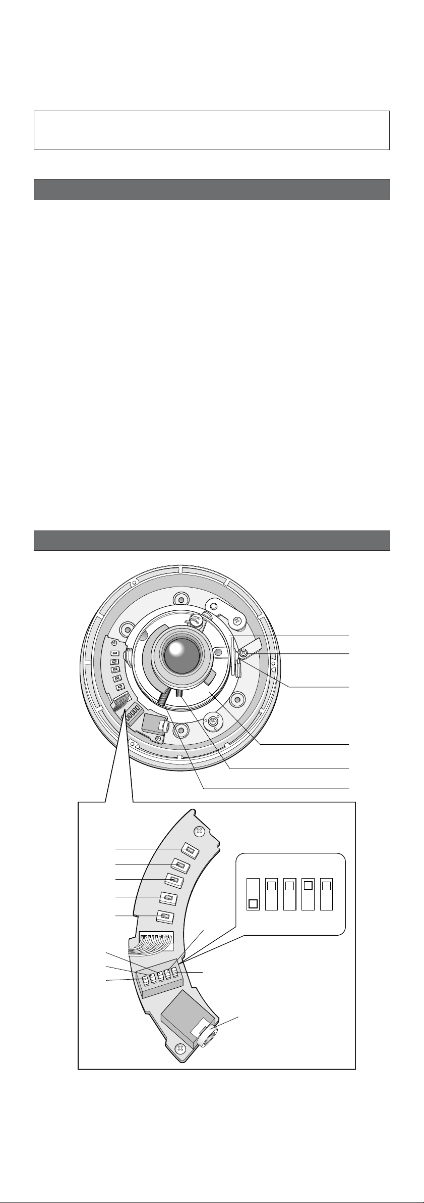
q Panning table
Adjusts the panning angle of the camera.
w Pan lock screw
Fixes the panning position.
e Tilting lock screw
Fixes the tilting position.
Caution:
To prevent fire or electric shock hazard, use a UL listed cable (VW-1, style 1007) for
the 24 V AC Input Cable.
q
w
e
r
y
t
L
D
U
OWN
R
IGHT
P
EFT
u
i
o
!0
!1
SET
!4
!3
!2
!5
!6
!7
LOW
HIGH
OFF
AUTO1
SHARP
SOFT
OFFONINT
LL
Page 3

Cautions:
1. Connect to 24 V AC (19.5 V-28 V) class 2 power supply only. Make sure to connect
the grounding lead to the GND terminal.
2. To prevent fire or electric shock hazard, use a UL listed cable (VW-1, style 1007) for
the Input Terminal.
!8 Power cable
!9 Video output cable with BNC connector
Connects with the video connector of the monitor.
@0 Dome cover
r AZIMUTH (Angle adjuster)
Shoots in a straight-angle field of view when aiming at an object in a slanting direction
even if the tilt angle has been set.
t Zoom lock lever
Fixes the zoom position.
y Focus lock lever
Fixes the focus position.
u LEFT button (I) (L)
Moves the cursor to the left, selects the mode and adjusts some levels.
i RIGHT button (I) (R)
Moves the cursor to the right, selects the mode and adjusts some levels.
o UP button (I) (U)
Moves the cursor upward and selects items in the CAM SET UP menu.
!0 DOWN button (I) (D)
Moves the cursor downward and selects items in the CAM SET UP menu.
!1 SET button (I) (S)
Activates an item selected in the CAM SET UP menu.
!2 BW AUTO1 LEVEL switch (SW5)
Selects the illuminance level in LOW or HIGH mode for B/W. The factory default setting
is HIGH.
!3 BW switch (SW4)
Switches to AUTO1 between colour and black-and-white picture in response to light
input. The factory default setting is OFF.
!4 AP gain switch (SW3)
Selects the aperture gain level to SHARP or SOFT. The factory default setting is SHARP.
Note: SHARP and SOFT are selectable only with this switch. Toggling between SHARP
and SOFT cannot be executed on the menu.
!5 UPSIDE DOWN switch (SW2)
Turns the picture upside down by selecting ON. The factory default setting is OFF.
!6 Sync switch (SW1)
Switches internal sync (INT) mode or line-lock (LL) mode. The factory default setting is
INT.
!7 Monitor output Jack (3.5 Diam. mini jack)
Connects the LCD monitor and such devices with 3.5 diam. 2-pole L-type plug for
checking images.
When the camera is aimed at a bright light,
such as a spotlight, or a surface that
reflects bright light, smear or blooming may
appear. Therefore, the camera should be
operated carefully in the vicinity of extremely bright objects to avoid smear or blooming.
PREVENTION OF BLOOMING AND SMEAR
Bright object
Smear
!8
!9
@0
Page 4

1. CAMERA SETUP MENU
This camera utilizes an on-screen user setup menu.
• Opening the Setup Menu
Press and hold down I(S) for 2 seconds or
more.
The CAM SET UP menu appears on the monitor
as shown at right.
Check the current settings on the menu.
• Returning to Previous Menu or Page
Move the cursor to RET and press I(S).
• Closing the Setup Menu
Move the cursor to END in the bottom line, and press I(S) to close the setup menu.
Note: If no button is pressed for 6 minutes while a setup menu is being displayed on the
monitor screen, it is automatically closed and the mode returns to the normal camera
picture.
2. SETUP OPERATION
To set items on the CAM SET UP menu, use the following buttons.
Left Button (I) (L): Moves the cursor to the left. Use this button to select or adjust the
parameters of the selected item. The parameter changes each
time this button is pressed.
Right Button (I) (R): Moves the cursor to the right. Use this button to select or adjust the
parameters of the selected item. The parameter changes each
time this button is pressed.
Up Button (I) (U): Moves the cursor upwards. Use this button to select an item or
adjust the parameters.
Down Button (I) (D): Moves the cursor downwards. Use this button to select an item or
adjust the parameters.
Set Button (I) (S): Executes selections and displays a submenu for an item with the
mark.
• All Reset Operation
All Reset allows you to reset all setup menu items to the factory default settings if you are
unsure about the correct settings. Proceed as follows:
(1) Make sure that the CAM SET UP menu is not displayed (a camera picture is displayed).
(2) While pressing both I(L) and I(R), press I(S) for a few seconds. The message
ALL RESET momentarily appears on the monitor screen.
This resets all adjustments and parameters to the factory default settings.
• Editing the CAM SET UP Menu
Enabling/Disabling the editing operations
The settings are protected from changing when SET UP DISABLE appears on the bottom
line in the menu.
Move the cursor to SET UP DISABLE and press I(S) to change it to SET UP ENABLE.
Editing the settings will be enabled. When editing is finished, return the menu to SET UP
DISABLE by the above procedure.
Using Menu or Five Switches
The DIP switches from SW1 to SW5 can
select the parameters of the allocated
functions by their positions while these
five functions are also included in the
menu screen. Depending on which you
use for setting, select DIP SW or MENU
on the second bottom line in the menu.
Move the cursor to DIP SW and press
I(S) to change it to MEMU. You can
change it from MENU to DIP SW in the
same way.
Note: When the setup menu is closed after changing the parameters in the menu, the new
values are stored in the EEPROM (Electrically Erasable and Programmable Read-Only
Memory). These values remain valid until new values are stored, even if the power of
the camera is off.
SETUP
** CAM SET UP **
CAMERA ID OFF
ALC ALC
SHUTTER --AGC ON(DNR-H)
SENS UP OFF
SYNC INT
WHITE BAL ATW1
MOTION DET OFF
DIP SW
END SET UP DISABLE
↵↵↵
↵
** CAM SET UP **
CAMERA ID OFF
ALC ALC
SHUTTER --AGC ON(DNR-H)
SENS UP OFF
SYNC INT
WHITE BAL ATW1
MOTION DET OFF
DIP SW
END SET UP DISABLE
↵↵↵
** CAM SET UP **
CAMERA ID OFF
ALC ALC
SHUTTER --AGC ON(DNR-H)
SENS UP OFF
SYNC INT
WHITE BAL ATW1
MOTION DET OFF
MENU
END SET UP ENABLE
↵↵↵
Page 5

1. Camera Identification (CAMERA ID) Setting
You can use the camera identification (CAMERA ID) to assign a name to the camera. The
camera ID consists of up to 16 alphanumeric characters. The camera ID display can be
switched on or off on the monitor screen.
To edit the CAMERA ID
1. Move the cursor to CAMERA ID.
The factory default setting is OFF.
2. Press I(S). The CAMERA ID menu
appears. The cursor on the letter “0” is
highlighted.
3. Move the cursor to the character you want
to edit by pressing I(L) / I(R) /
I(U) / I(D).
4. After selecting the character, press
I(S). The selected character appears
in the editing area. (The pointer in the
editing area moves to the right automatically at this moment.)
5. Repeat the steps above until all characters are edited.
To enter a blank space in the CAMERA ID
Move the cursor to SPACE and press I(S).
To replace a specific character in the CAMERA ID
1. Move the cursor to the editing area by pressing I(D).
2. Move the pointer to the character to be replaced by pressing I(L) or I(R). Then
move the cursor to the character area and select a new character.
3. Press I(S) to determine the CAMERA ID.
To erase all characters in the editing area
Move the cursor to RESET and press I(S). All characters in the editing area disappear.
To determine the display position of the CAMERA ID
1. Move the cursor to POSI, and press
I(S). The display at right appears and
the CAMERA ID is highlighted.
2. Move the CAMERA ID to the desired position by pressing I(L) / I(R) / I(U) /
I(D).
3. Press I(S) to fix the position of the
CAMERA ID. The mode returns to the previous CAMERA ID menu.
Notes:
• The CAMERA ID stops at the edges of the monitor screen.
• The CAMERA ID moves faster if any of I(L) / I(R) / I(U) / I(D) is kept
pressed for a second or more.
2. Light Control Setting (ALC)
2-1. ALC Mode with SUPER-D2 ON
Super Dynamic2 Function (SUPER-D2)
The important object in a scene is usually placed in the centre of the monitor screen. In the
SUPER-D2 mode, more photometric weight is given to the centre of the screen (where the
important object is located) than to the edge of the screen (where a bright backlight would
most likely be located). The SUPER-D2 function eliminates interference by strong background lighting which makes the camera picture dark, such as a spotlight.
1. Move the cursor to ALC and press I(S).
The ALC CONT menu appears.
2. Move the cursor to SUPER-D2 and select
ON.
3. If you want to adjust the video output
level, move the "I" cursor for LEVEL. Adjust
to the desired level by pressing I(L) or
I(R).
(To be continued reverse page)
SETTING PROCEDURES
Highlighted
Character Cursor
Pointer
Character
Area
Command
Editing
Area
CAMERA ID menu
0123456789
ABCDEFGHIJKLM
NOPQRSTUVWXYZ
().,'":;&#!?=
+-*/%$ДЬЦЖСЕ
SPACE
POSI RET END RESET
................
WV-CW474FE
** ALC CONT **
BACK LIGHT COMP
SUPER-D2 ON
LEVEL ...I.....
- +
RET END
Page 6

2-2. ALC Mode with SUPER-D2 OFF
1. Move the cursor to SUPER-D2 and
select OFF. The MASK SET appears on
the menu.
2. Move the cursor to MASK SET and
press I(S). The 48 mask areas
appear on the monitor screen. The cursor is blinking in the upper left corner
of the screen.
3. Move the cursor to the area where
backlight is bright and press I(S) to
mask that area. The mask turns to
white. (When the cursor is moved on
an area that has already been masked,
the mask and cursor start blinking.)
4. Repeat step 3 to mask the desired
area. To cancel masking, move the
cursor to that area and press I(S).
5. After masking is completed, press
I(S) for 2 seconds or more. The ALC
CONT menu appears.
6. If you want to change the video output
level (picture contrast), move the “I”
cursor for LEVEL and adjust the level.
Note: If ON is selected for SUPER-D2, a shadow (black line) may appear at the boundary
between the bright and the dim scene. This is a natural phenomenon and does not indicate trouble.
3. Shutter Speed Setting (SHUTTER)
Note: To select electronic shutter speed, select OFF for SUPER-D2 in the ALC CONT menu.
Move the cursor to SHUTTER and select the electronic shutter speed.
The preset values for SHUTTER (electronic shutter speed) change by pressing I(L) or
I(R) as follows:
The factory default setting is ---.
4. Gain Control Setting (AGC ON (DNR-L, DNR-H)/OFF)
You can set the gain (brightness level portion of an image) to automatic level adjustment.
Move the cursor to AGC and select automatic level adjustment ON (DNR-H), ON (DNR-L) or
fixed level (OFF).
ON (DNR-L): Selects lower noise reduction level.
ON (DNR-H): Selects higher noise reduction level.
OFF (Fixed Level): Disables the gain control function.
The factory default setting is ON (DNR-H).
Notes:
• If ON (DNR-H) is selected for the AGC, the noise reduction function is automatically
activated under low light conditions to reduce noise. In pictures containing a moving
object, this may result in an afterimage.
• DNR-L is recommended for pictures containing a moving object that results in an afterimage. However, the noise slightly increases.
• DNR-H and DNR-L do not appear for AGC on the system controller setup menu.
5. Electronic Sensitivity Enhancement (SENS UP)
There are two modes for SENS UP.
AUTO: If you select X10 AUTO, for example, the sensitivity is automatically raised to
X10 max. When AUTO is selected, AGC is automatically set to ON.
FIX: If you select X32 FIX, for example, the sensitivity is raised to just X32.
The factory default setting is OFF.
Move the cursor to SENS UP and select the parameter for electronic sensitivity enhancement.
The preset values for SENS UP (electronic sensitivity enhancement) change by pressing
I(L) or I(R) as shown right:
Notes:
• When ON is selected for SUPER-D2 in the ALC CONT menu, FIX is not available for this
item.
• When you select AUTO for SENS UP and ON for SUPER-D2, the SENS UP function has
priority so that the SUPER-D2 function is not activated automatically.
• While the SENS UP function is selected, noise, spots or a whitish phenomenon may
appear in the picture when the sensitivity of the camera is increased. This is a normal
phenomenon.
SETTING PROCEDURES
Blinking
Blinking
Blinking
Turns to white
** ALC CONT **
BACK LIGHT COMP
SUPER-D2 OFF
MASK SET
LEVEL ...I.....
- +
RET END
↵
OFF 1/120
1/10000 1/4000 1/2000 1/1000
1/250 1/500
OFF
X2 AUTO
X32 FIX X10 FIX X6 FIX X4 FIX X2 FIX
X4 AUTO X6 AUTO X10 AUTO
X16 FIX
OFF
Page 7

6. Synchronization Setting (SYNC)
Select one of the three sync source modes. The priority is as follows.
(1) Multiplexed Vertical Drive (VD2) (Highest priority)
(2) Line-lock (LL)
(3) Internal Sync (INT) (Lowest priority)
6-1. Line-lock Sync Mode (LL)
The line-lock mode has a submenu for line-lock vertical phase adjustment. If the camera
installation is relocated, check the vertical phase adjustment again since the AC line phase
may be different.
1. Move the cursor to SYNC and select LL.
Note: The settings in this menu can be
made only when the multiplexed
vertical drive signal (VD2) is not
supplied to the camera.
2. After confirming that the cursor is on LL,
press I(S). The vertical phase adjustment menu appears on the monitor
screen.
3. Supply the video output signal of the camera to be adjusted and the reference camera
video output signal to a dual-trace oscilloscope.
4. Set the oscilloscope to the vertical rate and expand the vertical sync portion on the
oscilloscope.
5. Move the cursor to COARSE. The cursor is highlighted.
6. Press I(L) or I(R) to match the
vertical phase for both video output
signals as closely as possible.
(COARSE adjustment can be incremented in 16 steps by 22.5 degrees by
pressing I(L) or I(R).)
Note: After the sixteenth step, the
adjustment returns to the first step.
7. Move the cursor to FINE.
8. Press I(L) or I(R) to match the vertical phase for both video output signals as
closely as possible.
(FINE adjustment can be made by up to 22.5 degrees by pressing I(L) or I(R).)
Notes:
• When the “I” cursor reaches the “+” end, it jumps back to “–”. At the same time,
COARSE is incremented by one step to enable a continuous adjustment. The
reverse takes place when the “I” cursor reaches the “–” end.
• When I(L) or I(R) is kept pressed for a second or more, the “I” cursor moves
faster.
• To reset COARSE and FINE to the values preset at the factory, press I(L) and
I(R) simultaneously. COARSE and FINE adjustments are preset at the factory to
zero-crossing of the AC line phase.
• If the AC line contains noise (spike noise, etc.), the stability of the vertical phase of
the camera video output signal may be disturbed.
7. White Balance Setting (WHITE BAL)
You can select one of four modes for white balance adjustment as follows.
The factory default setting is ATW1.
7-1. ATW1 (Auto-Tracing White Balance 1)
Move the cursor to WHITE BAL and select ATW1.
In this mode, the colour temperature is monitored continuously and thereby white balance is
automatically set. The colour temperature range for the proper white balance is approximately 2 600 - 6 000K. Proper white balance may not be obtained under the following conditions:
1. The colour temperature is out of the 2
600 - 6 000K range.
2. When the scene contains mostly high
colour temperature objects, such as a
blue sky or sunset.
3. When the scene is dim.
In these cases, select the AWC mode.
7-2. ATW2 (Auto-Tracing White Balance 2)
Auto-tracing white balance in sodium light mode (ATW2)
When you select ATW2 for sodium light, white balance is set automatically (no operation
needed).
Note: ATW1 and ATW2 do not appear for WHITE BAL on the system controller setup menu.
7-3.Automatic White Balance Control Mode (AWC)
In this mode, accurate white balance is obtained within a colour temperature range of
approximately 2 300-10 000K.
1. Move the cursor to WHITE BAL and
select AWC → PUSH SW.
2. Press I(S) to start the white balance
setup. The PUSH SW is highlighted to
indicate that the white balance is being
set.
3. When the white balance setting is completed, the PUSH SW returns to normal display.
Note: If white balance is not set, the PUSH SW is being highlighted.
4. When you want to adjust the white balance manually, press I(R) to select
AWC and press I(S). The AWC
menu appears on the monitor screen.
(When ATW1 or ATW2 is selected,
pressing I(S) displays the ATW1 or
ATW2 menu.)
Highlighted
** SYNC **
V PHASE
COARSE 1(1--16)
FINE I........
- +
RET END
1 (1 - - 16): 0 degrees
2 (1 - - 16): 22.5 degrees
16 (1 - - 16): 337.5 degrees
** CAM SET UP **
CAMERA ID OFF
ALC ALC
SHUTTER --AGC ON(DNR-H)
SENS UP OFF
SYNC INT
WHITE BAL ATW1
MOTION DET OFF
MENU
END SET UP ENABLE
↵↵↵
** CAM SET UP **
CAMERA ID OFF
ALC ALC
SHUTTER --AGC ON(DNR-H)
SENS UP OFF
SYNC INT
WHITE BAL AWC
MOTION DET OFF
MENU
END SET UP ENABLE
↵↵
→
PUSH SW
** AWC **
R ....I....
- +
B ....I....
- +
MASK SET
↵
RET END
Page 8

7-4. Manual Fine Adjustment for AWC (ATW1/ATW2)
You can set the white balance items manually.
1. To set MASK SET, proceed as described in steps 2 to 4 of “ALC mode with SUPER-D2
OFF".
2. Move the cursor to R.
3. Press I(L) or I(R) to obtain the optimum amount of red gain.
4. Move the cursor to B.
5. Press I(L) or I(R) to obtain the optimum amount of blue gain.
Note: When you need to set MASK SET, re-adjust to obtain the optimum amount of red and
blue gain.
8. Motion Detector Setting (MOTION DET)
The motion detector detects the moving objects in the scene by monitoring changes in
brightness level. You can select the level of sensitivity for motion detection.
When this camera is connected to a compatible intelligent CCTV system, the camera transmits an alarm signal by multiplexing it with the video signal.
1. Move the cursor to MOTION DET and
select ON.
The factory default setting is OFF.
2. Press I(S). The MOTION DETECT
menu appears on the monitor screen.
3. Move the cursor to MASK SET and press I(S). MASK SET lets you set 48 mask
areas. To set MASK SET, proceed as described in steps 2 to 4 of “ALC mode with
SUPER-D2 OFF”.
4. Move the cursor to ALARM and select ON or OFF to set the alarm for DISPLAY MODE.
Note: When using the WV-RM70, WV-CU550 series, WV-CU161 or WV-CU360 controller
with this model, select OFF for ALARM.
5. Move the cursor to DISPLAY MODE and press I(S) to see the current setting. The
masks that detect the brightness changes start blinking.
6. To raise detection sensitivity, press I(S) to return to the MOTION DETECT menu.
7. To obtain the optimum detection level, move the “I” cursor to adjust the level.
8. Repeat the procedures above to obtain a satisfactory setting.
Notes:
• Masking or adjusting the detection level is needed to prevent malfunction under the following conditions:
• When shooting an object under flickering fluorescent light.
• When leaves or curtains etc. are swayed by the wind.
• When the object is lighted by lighting equipment that constantly turns on and off.
• It takes about 0.2 seconds for the alarm signal to reach the alarm terminal of the VTR
after the camera detects the object.
Because the alarm signal is multiplexed on the video signal, it may be mistakenly interpreted by other video equipment as a time code signal.
Therefore, when the camera is not used in a Panasonic Intelligent CCTV System, select
OFF to prevent the above from occurring.
• The camera will deactivate the detector for a few minutes after the power of the camera
is turned on or the BW setting in the Special Menu is set to something other than OFF.
• The motion detection function is not designed specifically for prevention of theft, fire,
etc.
9. Special Menu
This menu lets you adjust and set up
the video signal of the camera to meet
your requirements.
Move the cursor to END in the bottom
line of the CAM SET UP menu and
press I(L) and I(R) simultaneously (holding down I(L) and press
I(R)) for 2 seconds or more. The
SPECIAL menu appears on the monitor
screen.
9-1. Camera Picture Upside Down Positioning (UP SIDE DOWN)
1. Move the cursor to UP SIDE DOWN.
2. Select ON when you want to turn the picture upside down.
9-2. Chroma Level Setting (CHROMA GAIN)
1. Move the cursor to CHROMA GAIN.
2. While observing the vectorscope or colour video monitor, move the “I” cursor to adjust
the chroma level.
9-3. Aperture Gain Setting
1. Move the cursor to AP SHARP.
2. While observing the waveform monitor or colour video monitor, move the “I” cursor to
adjust the aperture gain level.
9-4. Pedestal Level Setting (PEDESTAL)
1. Move the cursor to PEDESTAL.
2. While observing the waveform monitor or colour video monitor, move the “I” cursor to
adjust the pedestal level (black level).
** MOTION DETECT **
LEVEL ........I
- +
DISPLAY MODE
ALARM OFF
MASK SET
RET END
↵
↵
** CAM SET UP **
CAMERA ID OFF
ALC ALC
SHUTTER --AGC ON(DNR-H)
SENS UP OFF
SYNC INT
WHITE BAL ATW1
MOTION DET OFF
MENU
END SET UP ENABLE
↵↵↵
** SPECIAL **
UP SIDE DOWN OFF
CHROMA GAIN ....I....
AP SHARP ...I.....
PEDESTAL ......I..
- +
EL-ZOOM OFF
BW OFF
BURST(BW) ON
CAMERA RESET PUSH SW
RET END
Page 9

9-5. Electronic Zoom (EL-ZOOM)
1. Move the cursor to EL-ZOOM.
2. Select ON or OFF using I(L) or I(R).
The factory default setting is OFF.
ON: x2 electronic zoom is available with the ZOOM switch on the controller.
OFF: The electronic zoom function is disabled.
3. While the cursor is on EL-ZOOM, press
I(S). The EL-ZOOM setting menu
appears.
4. Move the cursor to PUSH SET for ZOOM
and press I(S) to display the ZOOM setting menu.
5. Press I(U) or I(D) to zoom in or out
the image.
6. Move the cursor to PUSH SET for PAN/TILT
and press I(S). The PAN/TILT setting
menu appears.
7. Press I(U) or I(D) I(L) or I(R) to
change the angular field of view.
8. To return to the EL-ZOOM setting menu,
press I(S).
9-6. BW
This function lets you switch from colour to black-and-white picture automatically in low light
conditions such as at night.
1. Move the cursor to BW.
2. Select AUTO1, AUTO2, ON or OFF using I(L) or I(R).
The factory default setting is OFF.
AUTO1: The camera selects black and white mode if the picture is dark, or colour
mode if the picture is bright enough.
AUTO2: Applying AUTO1 may cause malfunction when using a source of near-infrared
light at night because the illuminance changes significantly when switching
between the colour picture and a black-and-white picture. This can be prevented
by using the AUTO2 setting to detect the type of light source.
Notes:
• Because the type of light source is detected based on information received
from the CCD image pickup element, an object that is constantly moving or
has the same colour as its background may not always be properly recognized. When choosing the AUTO2 mode, make sure to use a light source having a wavelength of 800 nm or more.
• The object may be out of focus when using a source of near-infrared light than
using the visible light.
ON: Black-and-white mode enabled.
OFF: Colour mode enabled.
3. Select AUTO1 or AUTO2 using I(L) or
I(R).
4. Press I(S).
The AUTO1 or AUTO2 menu appears on
the monitor screen.
5. Move the “I” cursor to LEVEL to select the
illuminance level using I(L) or I(R).
The factory default setting is HIGH.
LOW: Colour picture switches to black-
and-white picture at approx.2 lx.
HIGH: Colour picture switches to black-and-white picture at approx.5 lx.
6. Move the “I” cursor for DURATION TIME to set the switching time using I(L) or
I(R).
The following switching times are available:
10s--30s--60s--300s
(S) (L)
9-7. BURST (BW)
1. Move the cursor to BURST (BW).
2. Select ON or OFF using I(L) or I(R).
ON: The burst signal is supplied along with the black-and-white composite video signal.
OFF: The burst signal is not output.
The factory default setting is ON.
Notes:
• We recommend that you usually select ON.
• When the camera is used to synchronize the system for external sync, select
ON to prevent a malfunction.
To reset to the factory settings (CAMERA RESET)
1. Move the cursor to CAMERA RESET. The PUSH SW is highlighted.
2. While holding down I(L) and I(R), press I(S) for 2 seconds or more. The cam-
era is reset to the factory settings.
To reset a specific parameter
• To reset the parameter to the factory default setting, move the cursor to the parameter
to be reset and press I(L) and I(R) simultaneously.
** EL-ZOOM **
PAN/TILT →PUSH SET
ZOOM →PUSH SET
U ZOOM D
RET END
** EL-ZOOM **
PAN/TILT →PUSH SET
ZOOM →PUSH SET
U TILT D/L PAN R
RET END
** BW AUTO1 **
LEVEL HIGH
DURATION TIME .I..
S L
RET END
Page 10

Pick-up Device: 752 (H) x 582 (V) pixels, Interline Transfer CCD
Scanning Area: 4.8 (H) x 3.6 (V) mm (Equivalent to scanning area of
1/3” pick-up tube)
Scanning: 625 lines/50 fields/25 frames
Horizontal: 15.625 kHz
Vertical: 50.00 Hz
Synchronization: Internal, Line-locked or Multiplexed vertical drive (VD2)
Sync selectable
Video Output: 1.0 V[p-p] PAL composite 75 Ω/BNC connector
Horizontal Resolution: 480 lines (C/L), 570 lines (B/W)
Signal-to-Noise Ratio: 50 dB (Equivalent to AGC Off, weight On, AP On)
Dynamic Range: 48 dB (Typ)
Minimum Illumination: 2.4 lx (0.24 footcandle) (WIDE) (C/L),
0.3 lx (0.03 footcandle) (WIDE) (B/W)
When the optional WV-CW1CE dome cover is installed.
0.8 lx (0.08 footcandle) (WIDE) (C/L),
0.1 lx (0.01 footcandle) (WIDE) (B/W)
Gain Control: ON (DNR-H), ON (DNR-L) or OFF (SET UP MENU)
selectable
White Balance: ATW1, ATW2 or AWC (SET UP MENU) selectable
Aperture: Set Variable (SET UP MENU)
Super Dynamic2: ON or OFF (SET UP MENU) selectable
Electronic Shutter Speed: OFF, 1/120, 1/250, 1/500, 1/1 000,1/2 000,
1/4 000, 1/10 000 s selectable
Lens
Focal length: 3.8 mm - 8 mm
Maximum aperture ratio: 1:1.4 (Wide), 1:1.8 (Tele)
Angular field of view: Horizontal: 35.6 ˚ - 73.6 ˚
Vertical: 26.6 ˚ - 53.4 ˚
Focusing range: 1.2 m - ∞ (3.9 ft - ∞)
Ambient Operating Temperature: –10 °C - +50 °C (14 °F - 122 °F)
Ambient Operating Humidity: Less than 90 %
Power Source and
Power Consumption: 24 V AC 50 Hz, 4.6 W
Dimensions: 133 mm (H) x 152.5 mm (D)
5-1/4” (H) x 6” (D)
Weights: 1.1 kg (2.4 lbs.)
Weights and dimensions indicated are approximate.
Specifications are subject to change without notice.
SPECIFICATIONS
OPTIONAL ACCESSORIES
STANDARD ACCESSORIES
Tamperproof screw bit ...................................................................... 1 pc.
WV-CW1CE Clear Dome Cover
WV-Q112E Camera mounting bracket
2002 © Matsushita Communication Industrial Co., Ltd. All rights reserved
Matsushita Electric Industrial Co., Ltd.
Web Site : http://www.panasonic.co.jp/global/
Page 11

2. Unscrew the red screw for
transport protection with a
Phillips screw driver.
3. Connect the power cable and the
BNC plug of the video output
cable as described in the section
"Connections".
■ Preface
Panasonic's WV-CW474FE colour digital camera is designed for installation on a wall or ceiling board.
■ Precautions
The following installation should be made by qualified service personnel or system
installers.
Be sure to use a ceiling board having enough strength to support this camera.
■ Preparations
The camera can be mounted either of the two ways shown below.
•Using Junction Box
Lay the two ganging junction box (4 in. x 4 in.) on a wall or ceiling. An example is shown
in the column at right.
Loosen three
screws.
Before attempting to connect or operate this product,
please read these instructions carefully and save this manual for future use.
N0502-0 3TU001041AAA Printed in Japan
N 19
Colour CCTV Camera
Instructions
Model No. WV-CW474FE
■ How to mount the camera
1. Remove the dome cover from the
main body by loosening the three
dome cover mounting screws.
The dome cover is fixed with tamperproof
screws.
Loosen the three dome cover mounting
screws by using the supplied bit for tamperproof screw.
(This procedure is also applicable to cases
where you replace the dome cover with an
optional Clear Dome Cover WV-CW1CE.)
85 mm
(3-3/8")
<Mounting hole pattern>
WV-Q112E
(option)
85 mm
(3-3/8")
Cable access hole for
3/4" pipe
Bracket center
51 mm
(2")
Camera mounting bracket
screw x 4 (procured locally)
4. Secure the camera with four camera mounting screws.
•Using Junction Box
Secure the camera on the junction box with four screws procured locally.
Purchase the screws to match the tapped holes of the junction box.
The mounting holes of this unit accept M4 screws or smaller.
Loosen the dome
cover mounting
screw x3
The serial number of this product may be found
on the top of the unit.
You should note the serial number of this unit
in the space provided and retain this instruction
as a permanent record of your purchase to aid
identification in the event of theft.
Model No.
Serial No.
WARNING:
To reduce the risk of fire or electric shock, do not expose this appliance to rain or moisture.
CAUTION: TO REDUCE THE RISK OF ELECTRIC SHOCK,
DO NOT REMOVE COVER (OR BACK).
NO USER-SERVICEABLE PARTS INSIDE. REFER SER-
VICING TO QUALIFIED SERVICE PERSONNEL.
CAUTION
RISK OF ELECTRIC
SHOCK DO NOT OPEN
Wij verklaren als enige aansprakelijke, dat het product
waarop deze verklaring betrekking heeft, voldoet aan de
volgende normen of andere normatiefve dokumenten,
overeenkomstig de bepalingen van Richtlijnen 73/23/
EEC en 89/336/EEC.
Vi erklærer os eneansvarlige for, at dette produkt, som
denne deklaration omhandler, er i overensstemmelse
med den følgende standarder eller andre normative
dokumenter i følge bestemmelserne i direktivene 73/23/
EEC og 89/336/EEC.
Vi deklarerar härmed värt fulla ansvar för att den produkt
till vilken denna deklaration hänvisar är i överensstämmelse med standarddokument, eller andra normativa
dokument som framstölls i Direktiv 73/23/EEC och 89/
336/EEC.
Ilmoitamme yksinomaisella vastuullamme, että tuote, jota
tämä ilmoitus koskee, noudattaa seuraavia standardeja
tai muita ohjeellisia asiakirjoja, jotka noudattavat direktiivien 73/23/EEC ia 89/336/EEC. säädöksiä.
Vi erklærer oss alene ansvarlige for at produktet som
denne erklæringen gjelder for, er i overensstemmelse
med følgende normer eller andre normgivende dokumenter som fælger bestemmelsene i direktiven 73/23/
EEC og 89/336/EEC.
We declare under our sole responsibility that the product
to which this declaration relates is in conformity with the
standards or other normative documents following the
provisions of Directives EEC/73/23 and EEC/89/336.
FOR YOUR SAFETY PLEASE READ THE FOLLOWING
TEXT CAREFULLY.
WARNING: This apparatus must be earthed.
IMPORTANT
The wires in this mains lead are coloured in accordance with
the following code.
Green-and-yellow: Earth
Blue: Neutral
Brown: Live
As the colours of the wire in the mains lead of this appliance may not correspond with the coloured markings identifying the terminals in your plug, proceed as follows.
The wire which is coloured green-and-yellow must be
connected to the terminal in the plug which is marked with the
letter E or by the earth symbol I or coloured green or
green-and-yellow.
The wire which is coloured blue must be connected to
the terminal in the plug which is marked with the letter N or
coloured black.
The wire which is coloured brown must be connected to
the terminal in the plug which is marked with the letter L or
coloured red.
The exclamation point within
an equilateral triangle is intended to alert the user to the presence of important operating
and maintenance (servicing)
instructions in the literature
accompanying the appliance.
The lightning flash with arrowhead symbol, within an equilateral triangle, is interned to alert
the user to the presence of
uninsulated "dangerous voltage" within the product's enclosure that may be of sufficient
magnitude to constitute a risk
of electric shock to persons.
• Using Optional Bracket WV-Q112E
An optional bracket WV-Q112E is available when you mount the camera on a flat surface with a cable access hole as shown in the figure. Purchase four screws locally to
secure the bracket on the surface. Another four screws are included with the bracket to
secure the camera on it.
Note: The WV-Q112E is not a waterproof type, so it requires sealing for outdoor use.
Refer to Waterproofing Process in the column at right.
46 mm
(1-13/16")
83.5 mm
(3-5/16")
Camera mounting screw x 4 (procured locally)
Seal the screws and screw holes with such a material as silicone
clay (rubber) to prevent entry of water if the camera is installed
outdoors.
Page 12

#18
(0.83 mm
2
)
■ Connections
Note: For the WV-CW474FE Colour CCTV Cameras, do not use a transformer larger than
10 VA.
1. Shrinking the cable-entry seal is a one-time procedure. Do not shrink the cable-entry
seal until it has been ascertained that the unit is functioning.
CONNECT THIS TO 24 V AC CLASS 2 POWER SUPPLY ONLY.
2. To prevent fire or electric shock hazard, the UL listed wire VW-1 style 1007 should
be used for the cable for 24 V AC Input Terminals.
CAUTIONS
• Power supply connection
Recommended wire gauge sizes for 24 V AC line.
#24
(0.22 mm
2
)
Copper wire size
(AWG)
Length of cable
(Approx.)
(m)
(ft)
#22
(0.33 mm2)
#20
(0.52 mm2)
20 30 45 75
65 100 160 260
■ Specifications
Dimensions: 133 mm (H) x 152.5 mm (D) [5-1/4” (H) x 6” (D)]
Weights: 1.1 kg (2.4 lbs.)
Weights and dimensions indicated are approximate.
Specifications are subject to change without notice.
■ Standard Accessories
Tamperproof screw bit ...................................................................... 1 pc.
(1) Loosen the pan lock screw (stain-
less) with the Phillips screwdriver.
Panning becomes adjustable.
(2) Loosen the tilting lock screw
(stainless) with the Phillips screwdriver.
Tilting becomes adjustable.
Note: Do not touch a black screw
placed on the opposite side.
(3) After adjusting panning and tilting,
tighten both of the lock screws
with the Phillips screwdriver.
(4) Adjust the azimuth.
If the image is slanting, turn the azimuth adjuster to obtain a leveled image.
6. Adjust the focus.
Precautions:
• The focus adjustment should be done at the same time as the camera angle adjustment.
• Set the zoom position to TELE before focusing.
(1) Loosen the focus lock screw by turning it counterclockwise.
The focus lock screw and the tip of the focus lever are identical with each other. The
focus lever becomes movable after loosening the focus lock screw.
(2) Adjust the focus by moving the focus lever to NEAR side or FAR side.
(3) Turn the focus lock screw clockwise to tighten the focus lever after adjustment.
Azimuth adjuster
5. Adjust the panning, tilting and azimuth while watching the monitor.
Notes:
• You can check images by connecting an LCD monitor and such devices to the
monitor output jack.
However, images are not available on the monitor connected
to the video output cable.
• The camera will select ELC
(Electronic Light Control) mode
to make more precise focus
adjustment possible when an
LCD monitor is connected. You
will need careful focus adjustment because the lens iris is
open in ELC mode.
• Do not aim the camera at an
extremely bright object, as this
may cause smear and blooming.
• Waterproofing Process
Apply waterproofing to the necessary portions, using appropriate materials.
a) Screw-holes, cable access holes, and gaps:
Fill these portions with silicon rubber or equivalent waterproofing material.
b) Cable joints:
• Use tape with electrical insulation and waterproof characteristics.
• Tape separately the three leads of the power cords, and cover the joint portions.
• Tape the joint portion of the video cables.
• Using Optional Bracket WV-Q112E
Secure the camera on the optional bracket using four screws included with the bracket.
Power cord
Video output cable
7. Adjust the zoom.
(1) Loosen the zoom lock screw by turning it counterclockwise.
The zoom lock screw and the tip of the zoom lever are identical with each other.
The zoom lever becomes movable after loosening the zoom lock screw.
(2) Adjust the zoom by moving the zoom lever to TELE side or WIDE side.
(3) Turn the zoom lock screw clockwise to tighten the zoom lever after adjustment.
8. Reinstall the dome cover to the
main body by tightening three
dome cover mounting screws.
(This procedure is also applicable to
cases where you replace the dome
cover with an optional Clear Dome
Cover WV-CW1CE.)
2002 © Matsushita Communication Industrial Co., Ltd. All rights reserved
Matsushita Electric Industrial Co., Ltd.
Web Site : http://www.panasonic.co.jp/global/
FAR
WV-Q112E
(option)
Camera mounting screw x 4
(included with WV-Q112E)
TELE
NEAR
WIDE
Zoom lock screw
Focus lock screw
Tighten the dome
cover mounting
screw x3
Variable angles
plus or minus 75 ° (max.)
Panning table
Pan lock screw
(stainless)
Tilting lock screw (stainless)
Monitor output jack (3.5 diam. minijack)
Black (Live)
24 V AC
BNC Plug
Video Output Cable
White (Neutral)
Green (Ground)
BNC Plug
To Video IN
(CAMERA IN)
BNC Plug
 Loading...