

Page 1
!6
!2
!4
!5
!3
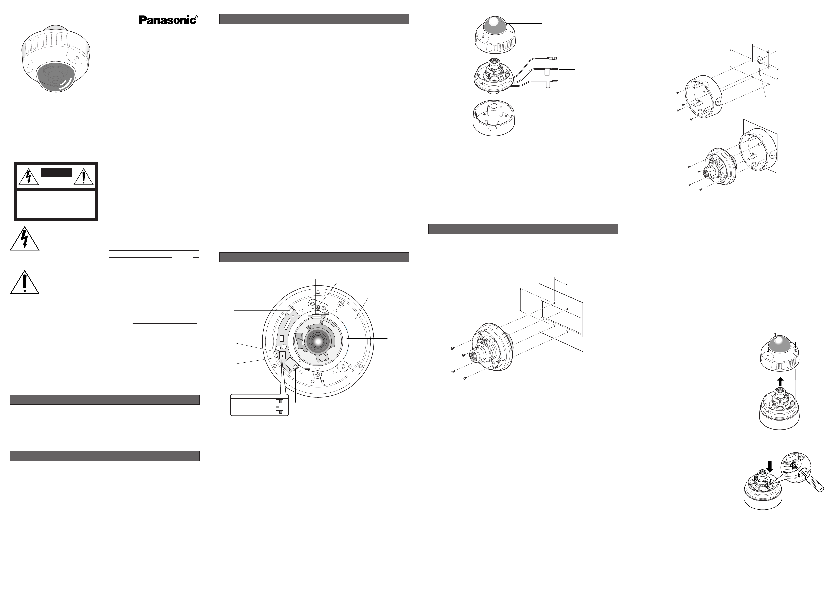
!2 Dome cover
!3 Video output cable with BNC connector
Connects with the video connector of the
monitor.
!4 Camera power cable
Supplies 24 V AC or 12 V DC from an external power source.
!5 Heater power cable
Supplies 24 V AC from an external power
source to an optional heater.
!6 Camera mounting bracket
Only WV-CW244S (surface mount type) is
supplied with a mounting bracket for ceiling
installation.
■ Installation Plans & Preparations
● WV-CW244F
“F” stands for flash mounting. This model can be mounted on a two-gang junction box (4“ x 4“) preinstalled in the wall or ceiling.
1. Space
Prepare a space larger than ø160 mm.
2. Junction box
Procure and install a junction box that meets the dimensions in the figure.
3. Camera Fixing Screws
Procure four screws (M4) suitable for the junction box.
4. Cable route
Cables will go behind the junction box.
5. Waterproof Process
When necessary, apply waterproof process to the camera and relevant portions.
Be sure to apply silicone rubber to the camera fixing screws in case of outdoor installation.
INSTALLATION
● WV-CW244S
“S” stands for surface mounting. This model can be installed on the surface of the wall or ceiling
using the supplied bracket.
1. Space
Prepare a space larger than ø160 mm.
2. Bracket Fixing Screws
To fix the bracket, procure four M4 screws suitable for the surface and structure of the wall/ceiling.
3. Camera Fixing Screws
Four screws are supplied as standard accessories.
4. Cable route
•When routing cables through the wall/ceiling, drill a hole as shown in the figure.
• When routing cables sideway, open the sideway cable exit unscrewing the lid by use of a hexagon wrench. Screw the detached lid to the cable access hole on the bottom of the bracket.
5. Waterproof Process
When necessary, apply waterproof process to the camera and relevant portions.
If you use camera fixing screws that are locally procured, be sure to apply silicone rubber to the
screws.
2. Remove the two red-colored screws provided for transport protection using a Philips
screwdriver.
■ Mounting the Camera
● Disassembly of the camera
1. Remove the dome cover by loosening three
tamper-proof screws using the supplied bit.
Color CCTV Camera
Operating Instructions
Model No.WV-CW244F
WV-CW244S
Before attempting to connect or operate this product,
please read these instructions carefully and save this manual for future use.
N0803-1093 3TR001693BAA Printed in Japan
PREFACE
The WV-CW244 series is a 1/3” CCD color camera designed for use in a video surveillance
system. The camera features a high picture
The exclamation point within an
equilateral triangle is intended to
alert the user to the presence of
important operating and maintenance (servicing) instructions in the
literature accompanying the appliance.
The lightning flash with arrowhead
symbol, within an equilateral triangle, is interned to alert the user to
the presence of uninsulated "dangerous voltage" within the product's
enclosure that may be of sufficient
magnitude to constitute a risk of
electric shock to persons.
The serial number of this product may be found on
the top of the unit.
You should note the serial number of this unit in the
space provided and retain this instruction as a permanent record of your purchase to aid identification
in the event of theft.
Model No.
Serial No.
SA 1966
SA 1965
WARNING: To prevent fire or electric shock hazard, do not expose this appliance to rain or moisture.
The apparatus shall not be exposed to dripping or splashing and that no objects filled with liquids, such
as vases, shall be placed on the apparatus.
CAUTION: TO REDUCE THE RISK OF ELECTRIC SHOCK,
DO NOT REMOVE COVER (OR BACK).
NO USER-SERVICEABLE PARTS INSIDE. REFER SER-
VICING TO QUALIFIED SERVICE PERSONNEL.
CAUTION
RISK OF ELECTRIC
SHOCK DO NOT OPEN
NOTE: This equipment has been tested and found
to comply with the limits for a Class A digital
device, pursuant to Part 15 of the FCC Rules.
These limits are designed to provide reasonable
protection against harmful interference when the
equipment is operated in a commercial environment. This equipment generates, uses, and can
radiate radio frequency energy and, if not installed
and used in accordance with the instruction manual, may cause harmful interference to radio communications.
Operation of this equipment in a residential area is
likely to cause harmful interference in which case
the user will be required to correct the interference
at his own expense.
FCC Caution: To assure continued compliance,
(example - use only shielded interface cables when
connecting to computer or peripheral devices). Any
changes or modifications not expressly approved
by the party responsible for compliance could void
the user’s authority to operate this equipment.
For U.S.A
quality thanks to the use of digital signal processing LSIs, and easy installation.
1. This product should be installed and connected by qualified service personnel or
system installers in conformity with NEC.
2. Use a class 2 power source supplying 12 V
DC or 24 V AC.
3. To prevent fire or electric shock hazard, use
a UL listed cable (VW-1, style 1007) to connect the power supply to the camera.
4. Be sure to use a ceiling board/wall having
enough strength to support this camera.
5. Handle the camera with care.
Do not abuse the camera. Avoid striking,
shaking, etc. The camera could be damaged by improper handling or storage.
6. Do not use strong or abrasive
detergents.
Use a dry cloth to clean the camera body
when dirty.
In case the dirt is hard to remove, use a
mild detergent and wipe gently. Afterwards,
wipe off the remaining detergent with a dry
cloth.
7. Clean the lens faceplate with care.
Do not clean the lens with strong or abrasive detergents. Use lens tissue or a cotton
tipped applicator and ethanol.
8. Never face the camera towards the sun.
Do not aim the camera at bright objects.
Whether the camera is in use or not, never
aim it at the sun or other extremely bright
objects. Otherwise, blooming or smear may
be caused.
9. Do not operate the camera beyond its
specifications.
Use the camera under conditions where
temperature is between –10 °C to +50 °C
(14 °F to 122 °F), and humidity is below
90 %. The input power source is 24 V AC or
12 V DC.
10. Use a monitor whose resolution is at least
equal to that of the camera.
PRECAUTIONS
• Mounting method: Flash mounting/WVCW244F, Surface mounting/WV-CW244S
• Signal processing: Automatic Light Control
(ALC), Automatic Gain Control (AGC),
Automatic Tracing White Balance (ATW),
etc.
• Synchronization: Internal, Line-Lock (only
24 V AC), and Multiplexed Vertical Drive
(VD2)
• Minimum illumination: 2.4 lx (0.24 foot-candle) at WIDE
• Signal-to-noise ratio: 50 dB (Equivalent to
AGC OFF)
• Horizontal resolution: 480 TV lines
• Optional heater unit available for the camera used at temperatures between –10 ˚C
and –30 ˚C (14˚F and –22˚F).
FEATURES
MAJOR OPERATING CONTROLS AND THEIR FUNCTIONS
q Focus lock lever
Fixes the focus position after adjusting.
w Tilting lock screw
Fixes the tilting position after adjusting.
e Zoom lock lever
Fixes the zoom position after adjusting.
r Panning table
Adjusts the panning angle of the camera.
t Azimuth adjuster
Adjusts the azimuth angle to obtain a level
image.
y Pan lock screw
Fixes the panning position after adjusting.
u Heater power connector
Supplies power to the optional heater unit
when it is built in the camera. Connect here
a harness sticking out from the heater unit.
i Synchronization Mode Selector
Specifies a source for synchronization.
INT: Internal 2:1 interlace.
LL: Line-lock mode driven by 24 V AC.
The default setting is INT.
Note: Do not set the switch to LL (Line-
Lock) position when supplying 12 V DC
to avoid synchronization error.
o Back Light Compensation Selector
ON:
Compensates the background if it is
brighter than the object.
OFF: Does not compensate.
The default setting is OFF.
!0 Aperture Level Selector
SHARP:
Sharpens the image outline.
SOFT: Softens the image outline.
The default setting is SHARP.
!1 Video jack (3.5-diam. mini jack)
For connecting an LCD monitor to adjust
the camera images. Use an L-type plug to
save space.
ON
123
OFF ON
LLSYNC INT*
OFF*BLC ON
SOFTAP SHARP*
2nd transport protection screw (Red)
Space for heater unit
qw
e
r
t
y
u
i
o
!0
!1
This Class A digital apparatus complies with canadian ICES-003.
Cet appareil numérique de la classe A est
conforme à la norme NMB-003 du Canada.
For Canada
* Default setting
46mm
(1-13/16")
83.5mm (3-5/16")
85 mm
Bracket fixing screw x 4
(procured locally)
Camera fixing screw x 4 (supplied)
85 mm
(3-3/8")
(3-3/8")
Bracket center
Cable access hole
for 3/4" pipe
(2")
51 mm
Camera fixing screw x 4 (procured locally)
2nd transport
protection screw
Page 2
SPECIFICATIONS
Pick-up device: 768 (H) x 494 (V) pixels, Interline transfer CCD
Scanning area: 4.8 (H) x 3.6 (V) mm (Equivalent to 1/3” pick-up tube)
Scanning: 525 lines/60 fields/30 frames
Horizontal: 15.734 kHz
Vertical: 59.94 Hz
Synchronization: Internal, Line-lock (only 24 V AC), or Multiplexed vertical drive
(VD2)
Video output: 1.0 V [P-P] NTSC composite 75 Ω/BNC connector
Horizontal resolution: 480 lines
Signal-to-noise ratio: 50 dB (Equivalent to AGC Off, weight On)
Minimum illumination: 2.4 lx (0.24 footcandle) (WIDE),
When the optional WV-CW2C dome cover is installed.
1.0 lx (0.1 footcandle) (WIDE),
Detail: SHARP or SOFT, selectable
White balance: ATW
Lens Mount: CS-mount
Lens
Focal length: 3.8 mm - 8 mm
Maximum aperture ratio: 1:1.4 (Wide), 1:1.8 (Tele)
Angular field of view: Horizontal: 35.6 ˚ - 73.6 ˚
Vertical: 26.6 ˚ - 53.4 ˚
Focusing range: 1.2 m - ∞ (3.9 ft - ∞)
Ambient operating temperature: –10 °C - +50 °C (14 °F - 122 °F)
–30 °C - +50 °C (–22 °F - 122 °F)
(When the optional heater unit built in)
Ambient operating humidity: Less than 90 %
Power source and
Power consumption: 12 V DC, 265 mA (Camera)
24 V AC 60 Hz, 3.0 W (Camera)
24 V AC 60 Hz, 12.1 W (Heater unit)
Dimensions: WV-CW244F: 133 mm (H) x 152.5 mm (D)
5-1/4” (H) x 6” (D)
WV-CW244S: 136.5 mm (H) x 160 mm (D)
5-3/8” (H) x 6-5/16” (D)
Weights: WV-CW244F: 1.2 k
g (2.7 lbs.)
WV-CW244S: 1.7 k
g (3.8 lbs.)
Weights and dimensions indicated are approximate.
Specifications are subject to change without notice.
OPTIONAL ACCESSORIES
STANDARD ACCESSORIES
Operating Instructions (this document) ............................................. 1 pc.
The following are for installation.
Tamperproof screw bit ...................................................................... 1 pc.
Camera mounting bracket (supplied only to WV-CW244S) ............... 1 pc.
Camera fixing screw (with a plastic washer) ..................................... 4 pcs.
(supplied only to WV-CW244S)
Heater unit ......................................................................................... WV-CW3H
Clear dome cover .............................................................................. WV-CW2C
Camera mounting bracket (for WV-CW244F) .................................... WV-Q112
PANASONIC CANADA INC.
5770 Ambler Drive, Mississauga,
Ontario, L4W 2T3 Canada (905)624-5010
PANASONIC SALES COMPANY
DIVISION OF MATSUSHITA ELECTRIC OF PUERTO RICO INC.
San Gabriel Industrial Park 65th Infantry Ave. KM. 9.5 Carolina,
P.R. 00985 (809)750-4300
Panasonic Digital Communications & Security Company
Unit of Matsushita Electric Corporation of America
Security Systems Group
www.panasonic.com/cctv
Executive Office: One Panasonic Way 3E-7, Secaucus, New Jersey 07094
Zone Office
Eastern: One Panasonic Way, Secaucus, NJ 07094 (201) 348-7303
Central: 1707 N.Randal Road, Elgin, IL 60123 (847) 468-5205
Western: 6550 Katella Ave., Cypress, CA 90630 (714) 373-7840
2003 © Matsushita Electric Industrial Co., Ltd. All rights reserved.
OPTIONAL HEATER UNIT
■ Optional Heater Unit WV-CW3H
● Introduction
Installing this heater unit enables the camera to operate under in a low-temperature environment of
–30°C (–22°F). The heater turns on automatically when the temperature inside the camera drops
below +10°C (50°F) and turns off when it rises.
A small fan inside the unit will minimize condensation on the surface of the dome cover caused by
changes in ambient temperature unless temperatures change too rapidly. The fan will stop when
there is no possibility of condensation.
● Precautions
• This product should be installed and connected by qualified service personnel or system
installers.
• Do not use the same 24 V AC power source supplying the power to the camera for the heater
unit. Connect another 24 V AC power source to the heater unit. If the same power source is
used, turning the heater on and off may disturb the camera images.
•When servicing, pay attention to high temperature on the surface of the unit. Disconnect the harness and wait until it cools.
•When you install the camera in a low-temperature location and start operating it, it may take time
(around 30 minutes) for the inside of the
camera to warm up. Cut power once then
supply power again.
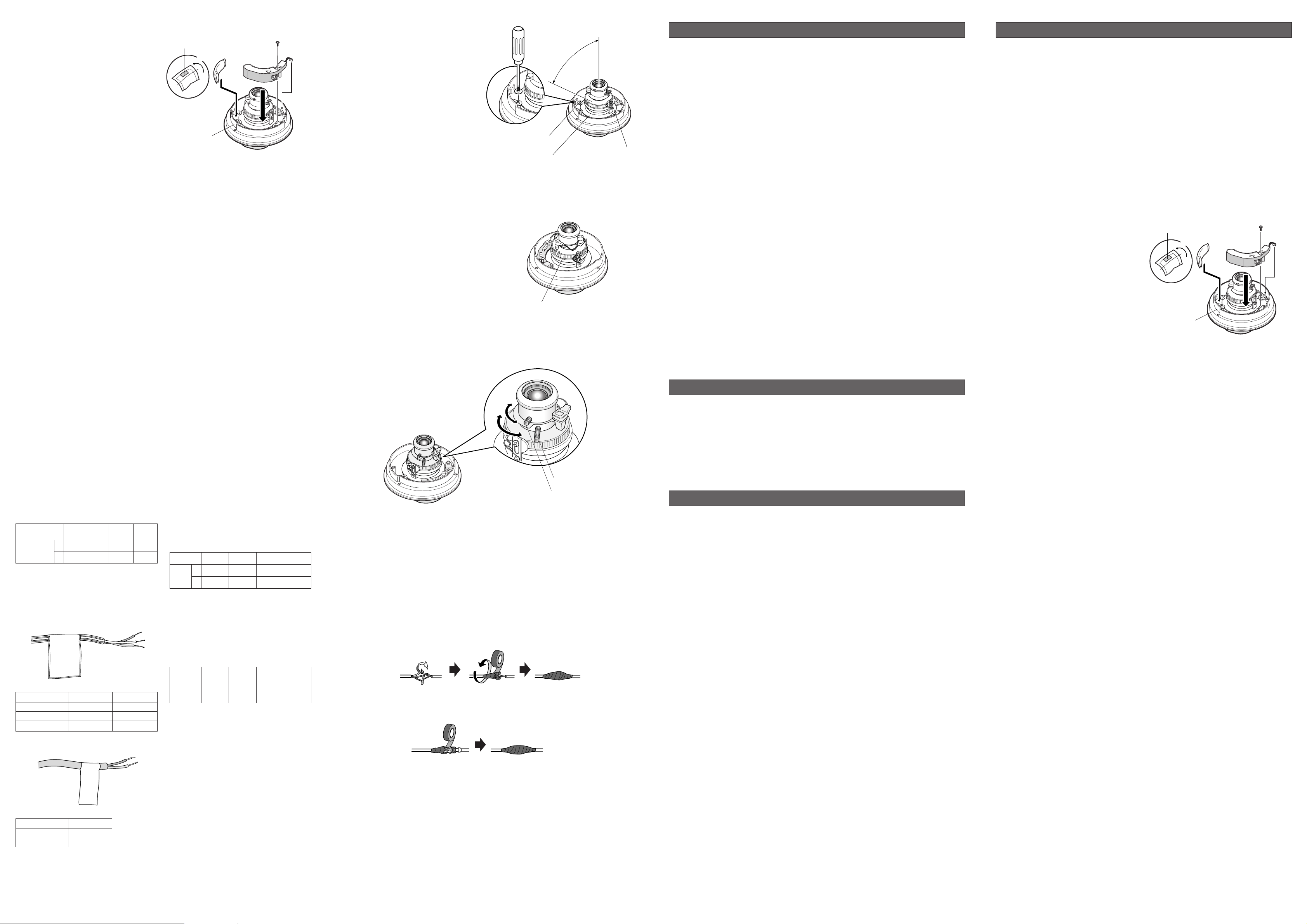
● Installation
1. Open the dome cover. (See Disassembling
the camera.)
2. Place the heater unit in the camera and fix
it with the supplied screw.
3. Insert the harness into the heater unit connector of the camera.
4. Fold the desiccant pack in half, and attach
it with adhesive tape to point "A" shown in
the figure.
Note: Attach the desiccant pack so that it
does not block ventilation holes or
hang over the top of the wall.
5. Attach the dome cover while paying attention not to pinch the harness cable.
6. Connect the heater power cable of the camera. (See Connection.)
● Specifications
Required power: 24 V AC, 60 Hz
Power consumption: 12.1 W maximum
Dimensions: 29 mm (H) x 83 mm (W) x 89.5 mm (D)
[1-1/8” (H) x 3-1/4”(W) x 3-1/2”(D)]
Weights: 45
g (0.1 lbs)
● Accessories
Fixing screw (M3 x 12) ...................................1 pc.
Desiccant pack .............................................1.pc.
● Heater unit installation
See OPTIONAL HEATER UNIT for details.
■ Connections
● Video Output Connection
Connect the video output connector to the monitor or other system device with the procured
coaxial cable. The maximum extensible length
is shown in the table.
● Power Connection
●
Wire Colors & Functions
Camera power cable
Heater power cable
Type of RG-59/U RG-6/U RG-11/U RG-15/U
coaxial cable (3C-2V) (5C-2V) (7C-2V) (10C-2V)
Recommended (m) 250 500 600 800
maximum
cable length (ft) 825 1 650 1 980 2 640
Wire Color 24 V AC 12 V DC
Black 24 V AC (L) Positive
White 24 V AC (N) Negative
Green/Yellow Ground Not Used
●
Cable Length and Wire Gauge
24 V AC
The recommended cable length and thickness are shown in the table for reference.
The voltage supplied to the power terminals
of the camera should be within 19.5 V AC
and 28 V AC.
12 V DC
Use the formula below to calculate the
power cable and power supply. The voltage
supplied to the power terminals of the camera should be within 10.5 V DC and 16 V
DC.
10.5 V DC ≤ VA − 2(R x I x L) ≤ 16 V DC
L : Cable length (m) (ft)
R : Resistance of copper wire (Ω/m) (Ω/ft)
VA : DC output voltage of power supply unit
I : DC current consumption (A). See spec-
ifications.
Copper wire
size (AWG)
Length of
Cable
(Approx.)
#24
(0.22 mm
2
)
95
314
#22
(0.33 mm2)
150
495
#20
(0.52 mm2)
255
842
#18
(0.83 mm2)
425
1 403
Recommended wire gauge for 24 V AC line.
Copper wire
size (AWG)
Resistance
Ω/m
Resistance
Ω/ft
#24
(0.22 mm
2
)
0.078
0.026
#22
(0.33 mm
2
)
0.050
0.017
#20
(0.52 mm
2
)
0.03
0.010
#18
(0.83 mm
2
)
0.018
0.006
Resistance of copper wire [at 20 °C (68 °F)]
(m)
(ft)
Wire Color 24 V AC
Red 24 V AC (L)
White 24 V AC (N)
Caution:
• Be sure to connect the GND (grounding)
lead of the camera and grounding terminal
of the power supply when using a 24 V AC
power source.
■ Image Adjustment
You can manually adjust the pan/tilt/azimuth
angles, focus, and zoom while observing the
connected monitor.
3. Zoom
• Unlock the zoom lever.
• Move the lever to adjust the zoom.
• Lock the lever.
4. Focus
• Unlock the focus lever.
• Move the lever to adjust the focus.
• Lock the lever.
5. Reinstalling the dome cover
• Attach the dome cover to the camera.
• Tighten the three tamper-proof screws.
● Waterproof Process
When necessary, apply waterproof process to protect the camera from water soak.
1. Power cord
First, tape the individual wires, finally all of them as a whole.
2. Connector junctions
Tape the BNC-BNC junction point.
3. Gaps and holes
Apply such a waterproof material as silicone clay (rubber) to the gaps, screws, holes, and other
relevant portions.
4. Camera Fixing Screws
WV-CW244F
Be sure to apply silicone rubber to the camera fixing screws in case of outdoor installation.
WV-CW244S
If you use camera fixing screws that are locally procured, be sure to apply silicone rubber to
the screws.
● Mounting the camera
1. Fix the camera to the installation surface.
WV-CW244F
• Fix the camera on the junction box using four screws (locally procured).
WV-CW244S
• Fix the supplied bracket on the wall/ceiling using four screws (locally procured).
• Fix the camera on the bracket using four screws (supplied).
2. Perform connections referring to
■ Connections.
3. Reinstall the camera to the bracket or junction box referring to step 1 above.
4. Adjust the image referring to
■ Image Adjustment.
5. Apply waterproof means referring to
● Waterproof Process.
Notes:
• Do not hold the camera by lens unit to
adjust panning, tilting, or azimuth.
• The video output to the BNC will be interrupted while an LCD monitor is connected
to the video jack.
1. Connect an LCD monitor to the video jack.
2. Pan/tilt/azimuth adjustment
• Loosen the two screws locking the pan and
tilt tables.
• Pan and tilt the table to aim the camera at
what you need to watch.
• Turn the azimuth adjuster to obtain a level
image.
• Tighten the two screws after adjusting.
Adhesive tape
Adhesive tape
Fold
Fold
Point “A”
Point “A”
(inside the wall)
(inside the wall)
Supplied screw
Supplied screw
Harness
Harness
Var iable angles
plus or minus 75 °
(max.)
Pan lock screw (stainless)
Panning table
Azimuth adjuster
Tilting lock screw
(stainless)
Adhesive tape
Adhesive tape
Fold
Fold
Point “A”
Point “A”
(inside the wall)
(inside the wall)
Supplied screw
Supplied screw
Harness
Harness
FAR
TELE
NEAR
WIDE
Zoom lock lever
Focus lock lever
Power cord
Video output cable
 Loading...