

Page 1
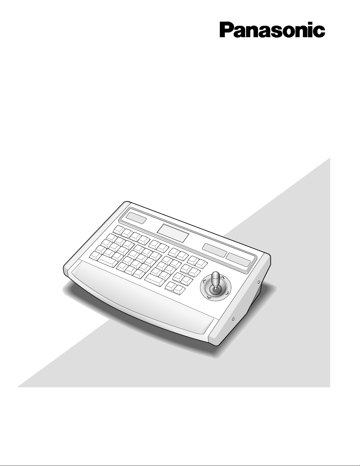
System Controller
Operating Instructions
Model No. WV-CU850
Before attempting to connect or operate this product,
please read these instructions carefully and save this manual for future use.
Page 2

Caution:
Before attempting to connect or operate this product,
please read the label on the bottom.
CAUTION
RISK OF ELECTRIC SHOCK
DO NOT OPEN
CAUTION: TO REDUCE THE RISK OF ELECTRIC SHOCK,
DO NOT REMOVE COVER (OR BACK).
NO USER-SERVICEABLE PARTS INSIDE.
REFER SERVICING TO QUALIFIED SERVICE PERSONNEL.
The lightning flash with arrowhead symbol, within an equilateral triangle, is
intended to alert the user to the presence of uninsulated "dangerous voltage"
within the product's enclosure that may
SA 1965
SA 1966
be of sufficient magnitude to constitute a
risk of electric shock to persons.
The exclamation point within an equilateral triangle is intended to alert the user
to the presence of important operating
and maintenance (servicing) instructions
in the literature accompanying the appliance.
For U.S.A
NOTE: This equipment has been tested and found to comply with the limits for a Class A digital device, pursuant to
Part 15 of the FCC Rules. These limits are designed to provide reasonable protection against harmful interference
when the equipment is operated in a commercial environment. This equipment generates, uses, and can radiate
radio frequency energy and, if not installed and used in
accordance with the instruction manual, may cause harmful
interference to radio communications.
Operation of this equipment in a residential area is likely to
cause harmful interference in which case the user will be
required to correct the interference at his own expense.
FCC Caution: To assure continued compliance, (example use only shielded interface cables when connecting to computer or peripheral devices). Any changes or modifications
not expressly approved by the party responsible for compliance could void the user’s authority to operate this equipment.
The serial number of this product may be found on the bottom of the unit.
You should note the serial number of this unit in the space
provided and retain this book as a permanent record of your
purchase to aid identification in the event of theft.
Model No. WV-CU850
Serial No.
2
WARNING:
To reduce the risk of fire or electric shock, do not expose this appliance to rain or moisture.
Page 3

CONTENTS
PREFACE ...................................................................................................................................................................................... 4
PRECAUTIONS ............................................................................................................................................................................. 4
MAJOR OPERATING CONTROLS AND THEIR FUNCTIONS ...................................................................................................... 5
■ Front View .............................................................................................................................................................................. 5
■ Rear View ............................................................................................................................................................................... 9
INSTALLATIONS .......................................................................................................................................................................... 10
SPECIFICATIONS ......................................................................................................................................................................... 11
STANDARD ACCESSORY ............................................................................................................................................................ 11
3
Page 4

PREF ACE
The WV-CU850 System Controller is designed to control
the System 850 Matrix Switcher.
It allows operators to perform the following functions when
combined with the System 850 Matrix Switcher.
• Log in and log out
• Switches camera video signals to monitors.
• Controls camera functions such as pan, tilt, zoom, and
focus.
PRECAUTIONS
• Refer all work related to the installation of this
product to qualified service personnel or system
installers.
• Do not attempt to disassemble the appliance.
To prevent electric shock, do not remove screws or
covers.
There are no user-serviceable parts inside. Contact
qualified service personnel for maintenance.
• Handle the appliance with care.
Do not strike or shake, as this may damage the appliance.
• Sets and calls camera preset positions.
• Activates pre-programmed group presets, tour and
group sequences.
• Acknowledges, and resets alarms.
• Do not use strong or abrasive detergents when
cleaning the appliance body.
Use a dry cloth to clean the appliance when it is dirty.
When the dirt is hard to remove, use a mild detergent
and wipe gently.
• Do not operate the appliance beyond its specified
temperature, humidity or power source ratings.
Use the appliance at temperatures within −10°C +50°C (14°F - 122°F) and a humidity below 90 %.
The input power source for this appliance is 120 V AC
60 Hz by use of exclusive AC adapter supplied.
• Do not expose the appliance to water or moisture,
nor try to operate it in wet areas.
Do take immediate action if the appliance becomes
wet. Turn the power off and refer servicing to qualified
service personnel. Moisture may damage the appliance and also cause electric shock.
4
Page 5

MAJOR OPERATING CONTROLS AND THEIR FUNCTIONS
ALARM
ACK
RESET
ALL
RESET
ARM
GROUP
PRESET
PREV
S-CTL IDOPE ID
NEXT
GROUP
SEQ
PAUSE STOP
TOUR
SEQ
REV
RUN
FWD
RUN
OSD
F.1 F.2 F.3
CMENU
OFF
F.4
CMENU
ON
F.5 F.6
CLOSE
IRIS
WIPER
OPEN
NEAR FAR
UP
BUSY
ACK
LOCK
CAMERA
INFORMATION
MONITOR
ALARM LINK OPERATE
DOWN
R
L
WIDE TELE
AUTO FOCUS
ZOOM
MONITOR
LOCK
OSD SERVICE
LOGOUT
AUX1 OFF AUX1 ON
CALL
PRESET
PGM
PRESET
CAM
POSI
DIGITAL
OUT
CAMERA
(ENTER)
CAM ID
VLD S
T&D
ALM S
GEN
SYS S
(
ALARM
)
0
87
DEF OFF
AUTO PAN
DEF ON
MSTA TUS
VLD H
ALL
ALM H
BLK
5964
231
SHIFT
CLEAR
(
ESC
)
EXIT
System Controller WU
–
CU 850
BUSY
AREA
AUX2 OFF AUX2 ON
DEFAULT
FOCUS
VER
CAM
FUNC
q rwe t y u i o !0
!1 !2 !3 !4 !5
!6
!7
!8!9
@0
@1@5@7
@8
@22
@4
@3
@6
#1#2#3#6
@9#4 #0#5
#8
#7
#9
$0
■ Front View
q Alarm Acknowledge indicator (ACK)
Lights up (red) when the activated alarm is acknowledged.
w Monitor Busy indicator (BUSY)
Lights up (red) when you attempt to control a monitor
that is already used by a higher priority operator, or
when a higher priority operator selects the monitor you
are currently operating.
Operations from the System Controller are disabled
until this indicator goes off.
e Monitor LED Display (MONITOR)
Displays the Monitor Number currently controlled.
r Monitor Lock Indicator (LOCK)
Lights (red) to indicate that the currently selected monitor is priority locked, and retains control of a monitor by
an operator.
Pressing the MONITOR key, while holding down the
SHIFT key, will toggle the indicator on and off.
t LCD (Liquid Crystal Display) Display
(INFORMATION)
Displays numeric input, system status, general status,
etc.
y Camera Busy indicator (BUSY)
u Camera LED Display (CAMERA)
i Alarm Indicator (ALARM)
Lights up (red) when you attempt to control a camera
that is already used by a higher priority operator, or
when a higher priority operator selects the camera you
are currently operating.
Operations from the System Controller are disabled
until this indicator goes off.
Displays the Camera Number currently controlled.
Lights (red) to indicate that an alarm condition exists.
To turn off the indicator, select the alarm by pressing
the Numeric and ALARM keys, then press the RESET
key.
5
Page 6

o Link Indicator (LINK)
Is on (green) when communication is established with
the Main CPU.
!0 Operate Indicator (OPERATE)
Is on (green) while the controller’s power is turned on.
!1 Alarm key (ALARM)
This key, in combination with the Numeric keys, is used
to select an alarm. To select an activated alarm, press
the Numeric keys, followed by the ALARM key.
!2 Alarm Acknowledge key (ACK)
Acknowledges an activated alarm.
To acknowledge the activated alarm, first select the
alarm by pressing the Numeric keys, followed by the
ALARM key. Select the desired alarm action number by
pressing the Numeric keys, then press the ACK key.
The ACK indicator will light.
After acknowledging the alarm, press the RESET key to
reset the alarm. The ACK indicator will go off.
!3 Alarm Reset key (RESET)
Cancels an activated alarm.
Press this key to reset an alarm activated in the currently active unit.
Pressing this key while holding down the SHIFT key
cancels all currently activated alarms at a time (ALL
RESET).
Pressing RESET in the Camera Menu will reset the
parameter of a selected item or open the Special
Camera Menu when the cursor is positioned on SPECIAL in the menu. Pressing it while holding down the
SHIFT key will restore all factory default settings.
!4 Alarm Arm key (ARM)
This key, in combination with the Numeric keys and
ALARM key, is used to arm or disarm cameras and
monitor for alarm response. Select an alarm number by
pressing the Numeric keys, followed by the ALARM
key. Then pressing this key repeatedly will enable or
disable the alarm activation with the selected alarm
input.
!5 Function keys (F1 - F6)
These keys provide access to camera attributes and
operating functions.
F1: Reserved for future use.
F2: Reserved for future use.
F3: Pressing F3 while holding down the SHIFT key will
close the Camera Menu on the active monitor
screen (CMENU OFF).
F4: Pressing F4 while holding down the SHIFT key will
open the Camera Menu on the active monitor
screen (CMENU ON).
F5: Reserved for future use.
F6: Pressing this key will select the mode for control-
ling selected camera function (CAM FUNC).
!65 Joystick Controller (L / R / UP / DOWN)
The joystick is used to manually operate the PAN/Tilt
Head, or move the cursor in the Camera Menu on the
active monitor screen.
UP: Upward
DOWN: Downward
L: Left
R: Right
!7 Iris Control keys (IRIS, CLOSE / OPEN)
Close or open the lens iris of cameras equipped with
the specified lens.
When these keys are pressed at the same time, the lens
iris is reset to the factory default setting.
These keys are also used to turn on the camera site
accessories. Pressing the CLOSE key while holding
down the SHIFT key will turn on the housing wiper of the
camera until the keys are released (WIPER).
!8 Focus Control keys (FOCUS, NEAR / FAR)
Adjust the lens focus of cameras equipped with the
specified lens.
Pressing these keys at the same time will automatically
set the lens focus if the specified camera with the auto
focus feature is equipped.
!9 Zoom Control keys (ZOOM, WIDE / TELE)
These keys are used for zooming cameras equipped
with the specified lens.
@0 Area key (AREA)
This key, in combination with the Numeric keys, is used
to change the monitoring area. Access is limited to
super users. Access by regular operators is prohibited.
The function allows users to apply logical numbers to
monitors.
Pressing this key while holding down the SHIFT key will
turn on the user's auxiliary 1 switch of the Receiver
(AUX1 ON).
@1 Program Preset key (PGM PRESET)
This key, in combination with the Numeric keys and
CAMERA (ENTER) key, is used to save a preset position of camera in a system equipped with the specified
cameras.
To save a preset position, move the camera to the position to be preset and select a preset number by pressing the Numeric keys. Hold down this key, then press
the CAMERA (ENTER) key.
Pressing this key while holding down the SHIFT key will
turn on the user's auxiliary 2 switch of the Receiver
(AUX2 ON).
6
Page 7

@2 Digital Output key (DIGITAL OUT)
This key, in combination with the Numeric keys, is used
to select a logical output number and produce a one
shot pulse for activating an assigned event.
Pressing this key while holding down the SHIFT key will
turn on the housing defroster of the camera (DEF ON).
@3 Log-out key (LOGOUT)
This key, in combination with the CAMERA (ENTER)
key, is used to log out from the system.
To prevent a log-out error, press CAMERA (ENTER)
while holding down the LOGOUT key.
Pressing this key while holding down the SHIFT key will
turn off the user's auxiliary 1 switch of the Receiver
(AUX1 OFF).
@4 Call Preset key (CALL PRESET)
This key, in combination with the Numeric keys, is used
to move to a preset position of the selected camera in a
system equipped with the specified cameras.
Pressing this key while holding down the SHIFT key will
turn off the user's auxiliary 2 switch of the Receiver
(AUX2 OFF).
@5 Camera Position key (CAM POSI)
This key, in combination with the Numeric keys, is used
to move the camera to the preset position programmed
in advance in a system equipped with the specified
cameras.
Pressing this key while holding down the SHIFT key will
turn off the housing defroster of the camera (DEF OFF).
@6 Camera / Enter key [CAMERA(ENTER)]
CAMERA: This key is used for camera selection. Press
the desired Numeric keys, then press this key to
select the camera.
ENTER: This key, in combination with the Numeric
keys, is used to enter numeric input, such as operator ID and password.
It is also used to execute the currently highlighted
selection and to enter a submenu of the Camera
Menu.
Pressing CAMERA (ENTER) while holding down the
SHIFT key will activate the auto panning function of the
selected camera (AUTO PAN).
@7 Clear / Escape key [CLEAR (ESC)]
Clear: This key is used to clear numeric input from the
LCD Display.
Escape: This key is used to escape from the currently
highlighted selection and return to the previous
page of the Camera Menu.
This key is also used to exit from alarm selecting mode
to normal operation mode.
@8 Numeric keys (0 - 9)
These keys are used for numeric input into the system
such as the camera and monitor number, sequence
number, preset position, etc.
@9 Shift key (SHIFT)
Pressing this key in combination with keys to which a
special functions has been assigned will activate these
functions.
#0 Next key (NEXT)
When a Tour Sequence running in forward direction has
been paused with the Pause key, pressing this key will
move the sequence one frame to the next step (in forward run direction). If the sequence was running in
reverse direction, the key will move the sequence one
frame to the next step (in reverse run direction).
The key is also used to select a camera. Pressing it
while holding down the CAMERA (ENTER) key will
replace the currently selected camera with the next
higher camera number, if the active monitor is in Spot
mode.
Similarly pressing this key while holding down the
MONITOR key will select the next higher monitor number.
When selecting alarms, pressing this key while holding
down the ALARM key will select the next alarm.
Pressing this key while holding down the SHIFT key will
display the software version of the system on the LCD
Display of the controller.
#1 Previous key (PREV)
When a Tour Sequence running in forward direction has
been paused with the Pause key, pressing this key will
move the sequence one frame to the previous step (in
forward run direction). If the sequence was running in
reverse direction, the key will move the sequence one
frame to the previous step (in reverse run direction).
The key is also used to select a camera. Pressing it
while holding down the CAMERA (ENTER) key will
replace the currently selected camera with the next
lower camera number, if the active monitor is in Spot
mode.
Similarly pressing this key while holding down the
MONITOR key will select the next lower monitor number.
When selecting alarms, pressing this key while holding
down the ALARM key will select the previous alarm.
Pressing this key while holding down the SHIFT key will
display the controller ID on the LCD display (S-CTL ID).
#2 Stop key (STOP)
This key is used to end a Tour Sequence that is being
run on the active monitor.
To end a Group sequence, select one of the monitors
that are being run on the sequence, then press this key.
7
#3 Pause key (PAUSE)
This key is used to pause a Tour or Group Sequence
that is being run on the active monitor.
Page 8

#4 Forward Run key (FWD RUN)
This key is used to run a selected Tour Sequence in forward direction on the active monitor.
It also restarts a Tour or Group Sequence forward from
the next step that was previously paused by pressing
the PAUSE key.
#5 Reverse Run key (REV RUN)
This key is used to run a selected Tour Sequence in
reverse direction on the active monitor.
It also restarts a Tour Sequence backward from the
next step that was previously paused by pressing the
PAUSE key.
#6 Monitor key (MONITOR)
This key is used to select a monitor.
To select a monitor, press the corresponding Numeric
keys, followed by the MONITOR key.
Pressing this key, in combination with the Numeric
keys, will display the status and history tables on the
active monitor screen.
#7 Group Preset key (GROUP PRESET)
This key, in combination with the Numeric keys, is used
to activate a previously programmed Group Preset
function.
Pressing this key while holding down the SHIFT key will
display the Operator ID on the LCD display (OPE ID).
#8 Group Sequence key (GROUP SEQ)
This key, in combination with the Numeric keys, is used
to run a Group Sequence forward on the assigned monitors.
#9 Tour Sequence key (TOUR SEQ)
This key, in combination with the Numeric and FWD
RUN (REV RUN) keys, is used to run a Tour Sequence
forward (backward) on the active monitor.
Select the desired tour number by pressing the
Numeric keys. Hold down this key and then press the
FWD RUN (REV RUN) key.
Note: By default, pressing TOUR SEQ after numeric
input will run the selected Tour Sequence forward.
$0 OSD (On Screen Display) key (OSD)
This key is used to toggle the currently selected display
on and off on the active monitor.
Pressing one of the numeric keys shown below while
holding down the OSD key will toggle the following display items on the active monitor on and off.
1: Clock Display (T & D)
2: Camera Title (CAM ID)
3: General Status (GEN)
5: Monitor Status (MSTATUS)
6: All Displays except clock (ALL)
8
Page 9

■ Rear View
RS–232C DATA
ETHERNET
CONTRAST BRIGHT BRIGHT
DC12V IN
ON OFF
POWER
LEDLCD
$1$2$3$4$5$6$7$8
$1 Power Switch (POWER, ON / OFF)
This switch turns the power of the System Controller on
and off.
$2 DC12V Input Jack (DC12V IN)
This jack is used to connect the AC Adapter supplied
with the System Controller.
$3 LED Brightness Control (LED BRIGHT)
Adjusts the brightness of the monitor and camera LED
display.
$4 LCD Brightness Control (LCD BRIGHT)
Adjusts the back light brightness of the LCD.
$5 LCD Contrast Control (LCD CONTRAST)
Adjusts the contrast of the characters displayed on the
LCD.
$6 Ethernet Port (ETHERNET)
Exchanges control data with the Central Processing
Unit (CPU) via Ethernet.
$7 Data Port (DATA)
Reserved for future use.
$8 RS-232C Port (RS-232C)
This port is used only for factory tests.
NOTE
Refer to the Operating Instructions of the System 850 Matrix
Switcher for further details.
9
Page 10

INSTALLA TIONS
The installation described below should be made by
qualified service personnel or system installers.
• Replacing the Side Panels with the optional WV-Q62
Rack Mounting Brackets
1. Remove both the left and right side panels of the
System Controller by removing four screws.
2. Remove the Palm-rest located on the front of the
System Controller by removing two screws.
3. Place the Rack Mounting Brackets on both sides of the
System Controller and tighten with the four supplied
screws.
4. Install the System Controller with Rack Mounting
Brackets in the rack by using four screws (procured
locally).
Side Panel
Palm-rest
Remove screws.
Rack Mounting Screws
Rack Mounting Bracket
Rack Mounting Screws
Tighten screws.
10
Page 11

SPECIFICATIONS
Controller
Power Required: 12 V DC 800 mA
Use exclusive AC Adapter supplied with the controller.
LED Display: 4 digits for Monitor, 5 digits for Camera
LCD Display: 160 x 64 dot matrix
Keys and Joystick: Numeric keys: 0, 1, 2, 3, 4, 5, 6, 7, 8, 9, SHIFT, CLEAR
Select keys: CAMERA, MONITOR
Sequence Control: GROUP PRESET, GROUP SEQ, TOUR SEQ
NEXT, PREV, STOP, PAUSE, FWD RUN, REV RUN
Camera Control: Joystick pan-tilt (Variable speed)
CLOSE, OPEN, NEAR, FAR, WIDE, TELE
Alarm Control: ACK, ALARM, RESET, ARM
Function keys: LOGOUT, AREA, CALL PRESET, PGM PRESET, CAM POSI, DIGITAL
OUT, OSD
Special Function keys: F1, F2, F3, F4, F5, F6
Ethernet Port: 10Base-T, 8-conductor Modular Jack
Data Output Port: 6-conductor Modular Jack (RS-485, Full Duplex)
RS-232C port: 9-pin D-sub connector
Ambient Operating Temperature: −10°C - +50°C (14°F - 122°F)
Ambient Operating Humidity: Less than 90%
Dimensions: 330 mm (W) x 74 mm (H) x 221 mm (D)
13” (W) x 2-15/16” (H) x 8-11/16” (D)
Weight: 2.2 kg (4.8 lbs.)
AC Adapter
Input: 120 V AC 60 Hz, 17 W
Output: 12 V DC, 800 mA
Weight and dimensions shown are approximate.
Specifications are subject to change without notice.
STANDARD ACCESSORY
AC Adapter 1 pc.
11
Page 12

Panasonic Security and Digital Imaging Company
A Division of Matsushita Electric Corporation of America
Executive Office: One Panasonic Way 3E-7, Secaucus, New Jersey 07094
Regional Offices:
Northeast: One Panasonic Way, Secaucus, NJ 07094 (201) 348-7303
Southern: 1225 Northbrook Parkway, Suite 1-160, Suwanee, GA 30024 (770) 338-6838
Midwest: 1707 North Randall Road, Elgin, IL 60123 (847) 468-5211
Western: 6550 Katella Ave., Cypress, CA 90630 (714) 373-7840
Panasonic Canada Inc.
5770 Ambler Drive, Mississauga,
Ontario, L4W 2T3 Canada (905)624-5010
Panasonic Sales Company
Division of Matsushita Electric of Puerto Rico Inc.
Ave. 65 de Infanteria. Km. 9.5
San Gabriel Industrial Park, Carolina,
Puerto Rico 00985 (809)750-4300
2001 © Matsushita Communication Industrial Co., Ltd. All rights reserved.
NM0899-2041 YWV8QA5246CN Printed in Japan
N 19
 Loading...