

Page 1
Before attempting to connect or operate this product,
please read these instructions carefully and save this manual for future use.
Model No. WV-CU360CJ
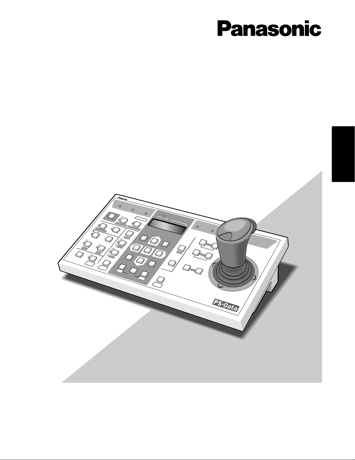
System Controller
Operating Instructions
System Controller WV-CU
360
CJ
O
PER
A
TE
LO
G
IN
A
LAR
M
M
O
N
IT
O
R
U
N
IT
C
AM
ER
A
BU
S
Y
PR
O
H
IBITE
D
S
H
IFT
FU
N
C
T
IO
N
C
AM
FU
N
C
TIO
N
P
RO
G
R
AM
ALM
R
E
SE
T
V
C
R
C
AM
MULTI SCREEN SELECT
STILL
–
SEQ PAUSE
SEQUENCE
SLOW
PATROL
LEARN
PROGRAM
PRESET
PATROL
STOP
ESC
SET
LOGOUT
MON
CAM
PATROL PLAY
+
A
U
X
1
W
IP
ER
H
O
M
E
/P
R
E
SE
T
AU
X
2
D
E
F
U
N
IT
B
ZO
O
M
W
ID
E
TE
LE
E
L
-Z
O
O
M
ALM RECALL
ALM
S
U
SP
E
ND
A
U
TO
FO
C
U
S
FAR
N
E
AR
U
N
IT
A
U
N
IT
B/W
SETUP
CAM SETUP
CLOSE
IRIS
OPEN
IRIS RESET
AUTO FOCUS
8
9
7
0
4
5
6
2
3
1
ENGLISH
Page 2
2
The serial number of this product may be found on the bottom of the unit.
You should note the serial number of this unit in the space
provided and retain this book as a permanent record of your
purchase to aid identification in the event of theft.
Model No. WV-CU360CJ
Serial No.
WARNING:
To reduce the risk of fire or electric shock, do not expose this appliance to rain or moisture.
Wij verklaren als enige aansprakelijke, dat het product waarop deze
verklaring betrekking heeft, voldoet aan de volgende normen of
andere normatieve documenten, overeenkomstig de bepalingen
van Richtlijnen 73/23/EEC en 89/336/EEC.
Vi erklærer os eneansvarlige for, at dette produkt, som denne
deklaration omhandler, er i overensstemmelse med standarder eller
andre normative dokumenter i følge bestemmelserne i direktivene
73/23/EEC og 89/336/EEC.
Vi deklarerar härmed värt fulla ansvar för att den produkt till vilken
denna deklaration hänvisar är i överensstämmelse med standarddokument, eller andra normativa dokument som framställs i EECdirektiv nr. 73/23 och 89/336.
Ilmoitamme yksinomaisella vastuullamme, että tuote, jota tämä
ilmoitus koskee, noudattaa seuraavia standardeja tai muita ohjeellisia asiakirjoja, jotka noudattavat direktiivien 73/23/EEC ja
89/336/EE. säädöksiä.
Vi erklærer oss alene ansvarlige for at produktet som denne
erklæringen gjelder for, er i overensstemmelse med følgende
normer eller andre normgivende dokumenter som følger bestemmelsene i direktivene 73/23/EEC og 89/336/EEC.
We declare under our sole responsibility that the product to which
this declaration relates is in conformity with the standards or other
normative documents following the provisions of Directives
EEC/73/23 and EEC/89/336.
Nosotros declaramos bajo nuestra única responsabilidad que el
producto a que hace referencia esta declaración está conforme con
las normas u otros documentos normativos siguiendo las estipulaciones de las directivas CEE/73/23 y CEE/89/336.
Noi dichiariamo sotto nostra esclusiva responsabilità che il prodotto
a cui si riferisce la presente dichiarazione risulta conforme ai
seguenti standard o altri documenti normativi conformi alle disposizioni delle direttive CEE/73/23 e CEE/89/336.
Wir erklären in alleiniger Verantwortung, daß das Produkt, auf das
sich diese Erklärung bezieht, mit der folgenden Normen oder normativen Dokumenten übereinstimmt. Gemäß den Bestimmungen
der Richtlinie 73/23/EEC und 89/336/EEC.
Nous déclarons sous note seule responsabilité que le produit
auquel se réfère la présente déclaration est conforme aux normes
ou autres documents normatifs conformément aux dispositions des
directives CEE/73/23 et CEE/89/336.
ENGLISH VERSION
The lightning flash with arrowhead symbol,
within an equilateral triangle, is intended to
alert the user to the presence of uninsulated
"dangerous voltage" within the product's enclosure that may be of sufficient magnitude to
constitute a risk of electric shock to persons.
The exclamation point within an equilateral triangle is intended to alert the user to the presence of important operating and maintenance
(servicing) instructions in the literature accompanying the appliance.
CAUTION: TO REDUCE THE RISK OF ELECTRIC SHOCK,
DO NOT REMOVE COVER (OR BACK).
NO USER-SERVICEABLE PARTS INSIDE.
REFER SERVICING TO QUALIFIED SERVICE PERSONNEL.
CAUTION
RISK OF ELECTRIC SHOCK
DO NOT OPEN
CAUTION:
Before attempting to connect or operate this product, please read the label on the bottom.
Page 3

3
CONTENTS
PREFACE .......................................................................... 4
FEATURES ........................................................................ 4
PRECAUTIONS ................................................................. 5
MAJOR OPERATING CONTROLS & THEIR FUNCTIONS
.... 6
■ Rear View & AC Adapter ............................................ 6
INSTALLATIONS ............................................................... 6
■ Palm Rest Mounting ................................................... 6
■ Template Mounting .................................................... 6
■ Rear Panel Switch Setting (Summary) ....................... 7
Chapter 1
For Panasonic Security Data (PS
•
Data) Systems ........ 9
MAJOR OPERATING CONTROLS & THEIR FUNCTIONS
.... 10
■ Front View (Template for PS
•
Data) .............................10
INSTALLATIONS (PS
•
Data) .............................................. 13
■ System Connections .................................................. 13
■ DIP Switch Setting (PS
•
Data) ..................................... 15
■ Controller Number Setting (PS
•
Data) .........................16
CONTROLLER SETUP PROCEDURES (PS
•
Data) ............ 17
■ Prior to Setup ............................................................. 17
■ Buttons and Controls Used for Setup ......................... 17
■ Setup Menus .............................................................. 18
OPERATING PROCEDURES (PS
•
Data) ........................... 22
■ Basic Operating Flow.................................................. 22
■ Log-in/Log-out............................................................. 23
■ System Unit Selection ................................................ 24
■ Monitor Selection ....................................................... 25
■ Camera Selection ....................................................... 25
■ Camera Control .......................................................... 26
■ Data Multiplex Unit Control ........................................ 28
■ Video Multiplexer Control ........................................... 29
■ Digital Disk Recorder Control .................................... 31
■ Alarm Operation ......................................................... 34
REMOTE SETUP of UNITS & CAMERAS .......................... 35
■ System Unit Setup ...................................................... 35
■ Camera Setup ............................................................ 35
■ Camera Patrol Learning ............................................. 36
■ Camera Preset Position .............................................. 37
Chapter 2
For WJ-FS616C Multiplexer System ............................. 39
MAJOR OPERATING CONTROLS & THEIR FUNCTIONS
.... 40
■ Front View (Template for WJ-FS616C) ....................... 40
INSTALLATIONS (For WJ-FS616/FS616C) ....................... 43
■ System Connections .................................................. 43
■ DIP Switch Setting (For Multiplexer) ........................... 44
■ Controller Number Setting ......................................... 45
SETUP PROCEDURES (For WJ-FS616/FS616C) .............. 46
■ Prior to Setup ............................................................. 46
■ Buttons and Controls Used for Setup ........................ 46
■ Controller Setup ......................................................... 47
OPERATING PROCEDURES (For WJ-FS616/FS616C) .... 49
■ Camera Selection ....................................................... 49
■ Camera Control .......................................................... 49
■ Alarm Operation ......................................................... 50
■ VTR (VCR) Control ..................................................... 50
■ Camera Setup ............................................................ 51
Chapter 3
For System 850 WJ-SX850 Matrix Switcher System ... 53
MAJOR OPERATING CONTROLS & THEIR FUNCTIONS
.... 54
■ Front View (Template for System 850
Matrix Switcher) ......................................................... 54
INSTALLATIONS (For System 850) .................................. 58
■ System Connections .................................................. 58
■ DIP Switch Setting ...................................................... 60
■ Controller Number Setting ......................................... 60
SETUP PROCEDURES (For System 850) ......................... 61
■ Prior to Setup ............................................................. 61
■ Buttons and Controls Used for Setup ........................ 61
■ Setup Procedures ...................................................... 62
OPERATING PROCEDURES (For System 850) ................ 63
■ Log-in & Log-out ........................................................ 63
Chapter 4
For WJ-SX150 Matrix Switcher System ........................ 65
MAJOR OPERATING CONTROLS & THEIR FUNCTIONS
.... 66
■ Front View (Template for WJ-SX150) ......................... 66
INSTALLATIONS (For WJ-SX150) .................................... 69
■ System Connections .................................................. 69
■ DIP Switch Setting (Terminal-mode) .......................... 70
■ Controller Number Setting ......................................... 71
SETUP PROCEDURES (For WJ-SX150) ........................... 72
■ Prior to Setup ............................................................. 72
■ Buttons and Controls Used for Setup ........................ 72
■ Setup Procedures ...................................................... 73
OPERATING PROCEDURES (For WJ-SX150) .................. 74
■ Log-in.......................................................................... 74
■ Log-out........................................................................ 75
■ Auto Log-in.................................................................. 75
■ Auto Log-out ............................................................... 75
Appendix ......................................................................... 77
SPECIFICATIONS ............................................................. 78
STANDARD ACCESSORIES ............................................. 78
ALL RESET ....................................................................... 79
ENGLISH
Page 4

4
PREF ACE
The System Controller WV-CU360CJ is designed for setup
and operation of cameras and other system units installed
in a surveillance system.
The controller is compatible with the Panasonic Security
Data (PS
•
Data) protocol by default, but DIP switches are
provided to select the conventional communication protocol
used with the Video Multiplexer WJ-FS616C or Matrix
Switcher WJ-SX850. Exchangeable templates are supplied
to adapt the names printed on the buttons to the functions
of the unit you wish to control.
You can operate a whole system from the controller, for
example, by selecting cameras and monitors, watching
monitor screens and indicators, and controlling pan/tilt, lens
and other camera functions.
FEATURES
Main features
• Camera channel selection
• Monitor Selection
• Alarm (Display/Suspend/Recall/Reset)
• Camera and system unit setup
Camera controls
• Lens functions: Iris/Focus/Auto Focus/Zoom
• Housing: Defroster/Wiper/Auxiliary 1, 2
• Pan/Tilt: Slow Pan/Slow Tilt/Auto Pan/Auto Sort/Auto
Sequence/Random Pan/Preset/Home/Camera Patrol
• Single-handed control of pan/tilt, zoom, and auto focus
functions
In a PS
•
Data or a WJ-FS616 system
• Switching of Live pictures and Playback/Changing the
Multiscreen Picture layout/Electronic Zoom/Sequence
• System Unit Selection
PRECAUTIONS
• Refer all work related to the installation of this
product to qualified service personnel or system
installers.
• Do not attempt to disassemble the appliance.
To prevent electric shock, do not remove screws or
covers.
There are no user-serviceable parts inside. Contact
qualified service personnel for maintenance.
•Handle the appliance with care.
Do not strike or shake, as this may damage the appliance.
• Do not expose the appliance to water or moisture,
nor try to operate it in wet areas.
Take immediate action if the appliance becomes wet.
Turn the power off and refer servicing to qualified service personnel. Moisture may damage the appliance
and cause electric shock.
•Do not use strong or abrasive detergents when
cleaning the appliance body.
Use a dry cloth to clean the appliance when it is dirty.
When the dirt is hard to remove, use a mild detergent
and wipe gently.
• Do not operate the appliance beyond its specified
temperature, humidity or power source ratings.
Do not use in the appliance in an extreme environment
where high temperature or high humidity exists.
Use the appliance at temperatures within –10˚C to
+50˚C (14˚F to 122˚F) and a humidity below 90 %. The
input power source for this appliance is 220 V to 240 V
AC 50 Hz by use of the AC Adapter supplied.
•Do not use any AC adapter other than the one
supplied.
Page 5
5
MAJOR OPERATING CONTROLS & THEIR FUNCTIONS
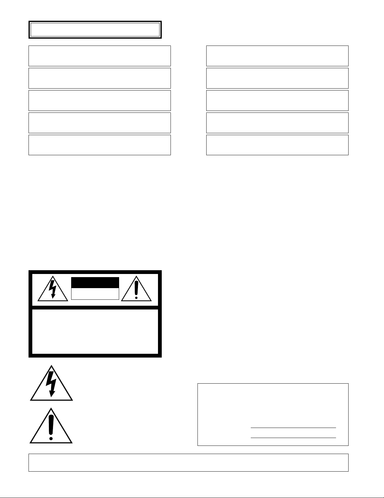
■ Rear View & AC Adapter
DC 9V IN
DAT AMODE
RISK OF ELECTRIC
SHOCK. DO NOT OPEN
RISQUE DE CHOCS ELECTROUES
NE PAS OUVRIR
0
9
8
7
6
5
4
3
2
1
r te
CONTROLLER No.
w
q
q Controller Number Switch (CONTROLLER No.)
This switch is used to assign a controller number to the
System Controller to identify it in a system comprising
multiple System Controllers (See page 14). A system
may comprise up to four controllers.
w Mode Selection Switches (MODE)
The DIP switches are used to set communication parameters for the System Controller.
e Data Ports (DATA)
These ports are used to exchange control data with the
connected system units via the supplied RS-485 cable.
r DC 9 V Input Jack (DC 9V IN)
Jack for the DC plug of the supplied AC adapter.
t Clamp
The clamp fastens the power cord to the AC adapter.
y AC Adapter
Caution:
Use only the supplied AC adapter to feed DC 9 V to a
System Controller.
Note: Disconnect the plug from the controller before
setting the controller number switch or mode selection switch, and reconnect it when finished. The
new settings will take effect when the power is
turned on.
DC 9V IN
y
Page 6
6
INSTALLA TIONS
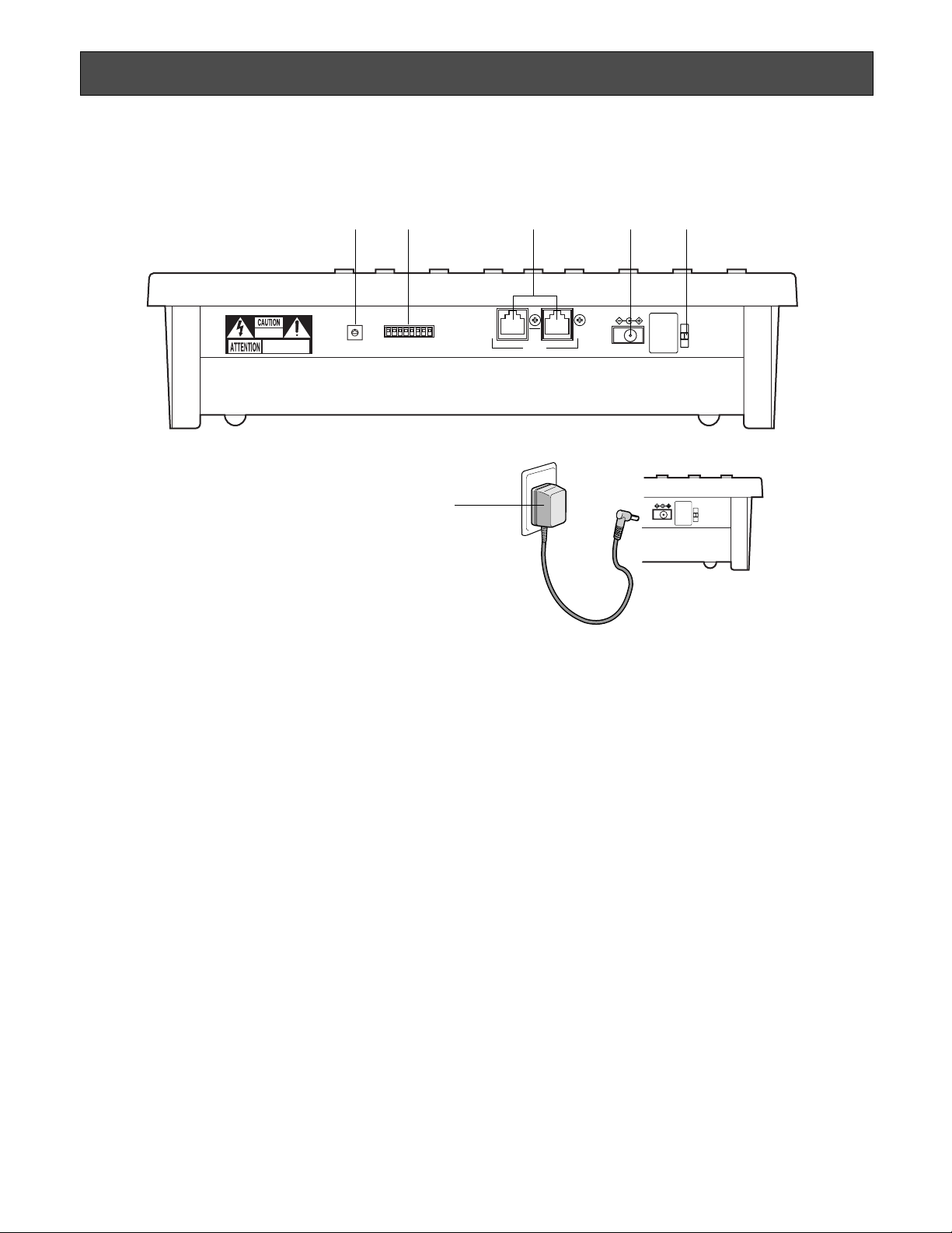
■ Template Mounting
The system controller is provided with four templates
including one for PS
•
Data system that is placed (not taped
yet) on the surface of the controller when shipped from the
factory.
1. Select the correct template for your system.
• Select the PS
•
Data template when your system
includes any of the following:
Video Multiplexer (WJ-FS309/316/409/416)
Digital Disk Recorder (WJ-HD100/500A)
Data Multiplex Unit (WJ-MP204C)
• Select the template marked “For Multiplexer” if your
system includes a WJ-FS616C Video Multiplexer.
• Select the template marked “For Matrix Switcher
(System SX850)” if your system includes a WJ-SX850
Matrix Switcher.
• Select the template marked “For Matrix Switcher (WJSX150)” if your system includes a WJ-SX150 Matrix
Switcher.
OPERATE LOGIN ALARM
CAM SETUP
PROGRAM
PROGRAM
PRESET
UNIT A
IRIS
CLOSE OPEN
NEAR FAR
WIDE TELE
FOCUS
ZOOM
AUTO FOCUS
IRIS RESET
AUTO
SETUP
ALM SUSPEND
FUNCTION
CAM FUNCTION
MULTI SCREEN SELECT
DEF
WIPER
EL-ZOOM
SHIFT
ALM RESET
VCR CAM
STILL
–
+
ALM RECALL
PATR OL
LEARN
PATR OL
STOP
AUX 1
AUX 2
B/W UNIT
SEQ PAUSE
SLOW
SEQUENCE
PATR OL PLAY
HOME/PRESET
UNIT B
MON
CAM
LOGOUT
ESC SET
BUSY PROHIBITED
MONITOR
UNIT
CAMERA
System ControllerWV-
CU CJ
360
AUTO FOCUS
OPERATE LINK ALARM BUSY PROHIBITED
IRIS
CLOSE OPEN
NEAR FAR
WIDE TELE
FOCUS
ZOOM
IRIS RESET
PREV
SEQ
SEQ
TOUR
GROUP
ALARM
DISARM
ACK
RESET
GROUP PRESET
NEXT
LOG OUT PAUSE STOP
F1
F2 MONITOR
CAM FUNC LOCK
OSD SERVICE
CAMERA
(ENTER)
CLEAR
(ESC)
CALL
PRESET
PROGRAM
PRESET
SHIFT
DEF OFF DEF ON
AUX2 OFF AUX2 ON
AUX1 OFF AUX1 ON
CAM IDT&D
OPE ID S-CTL ID
OSD
CAM MENU OFF CAM MENU ON
ALL RESET
MDN STATUS
WIPER
GEN
ALL
EXITBLK
VLD HALM H
VLD S SYS SALM S
AUTO
PAN
For Matrix Switcher (System 850)
WV-CU CJ
360
System Controller
MONITOR CAMERA
System Controller
OPERATE LOCK ALARM
SPOT
AUTO/+
IRIS
CLOSE OPEN
NEAR FAR
TELE WIDE
FOCUS
ZOOM
IRIS RESET
VTR
CAM
MULTI
SCREEN
SEQUENCE
EL-ZOOM
MULTI SELECT
STILL
PRE-POSI
ALT
ALM RESET
ALM SUSPEND
FUNCTION
ALL RESET
CAMERA SET
ON OFF ON/OFF
SETUP
AUTO
FOCUS
HOME/-
UNIT
CAM
ESC SET
UNIT CAMERA
For Multiplexer
WV-CU CJ
360
T/L MODE
CAMERA SITE CONTROL
AUX 2
AUX 1
SETUP
SHIFT
REW/FF
STEP
AUTO FOCUS
OPERATE LINK ALARM BUSY PROHIBITED
CALL
PRESET
PROGRAM
PRESET
IRIS
CLOSE OPEN
NEAR FAR
WIDE TELE
FOCUS
ZOOM
AUTO IRIS
GROUP SEQ
PAUSE
SUSPEND
F1
CAM SETUP
ALL RESET
ACK RESET
F2
TOUR SEQ
PREV NEXT
STOP
OSD
AUTO PAN
MONITOR CAMERA
For Matrix Switcher (WJ-SX150)
WV-CU CJ
360
System Controller
RECORDER
INDEX
STOP PLAY
REC
PAUSE
CAM FUNC
CLEAR
LOG OUT
MON LOCK
DEF ON
WIPER
DEF OFF
MON (ESC)
T&D CAM ID
MON STATUS
ALL
EVENT
ALM H VLD H SYS S
CAM (SET)
MULTI SCREEN SEL
SEQUENCE
AUX2 ONAUX2 OFF
EL-ZOOM
AUX1 ONAUX1 OFF
STILL
For PS•Data
For FS616C
For SX850
For SX150
■ Palm Rest Mounting
Hook the projections of the palm rest on the system controller.
Note: There is no screw fixing. When using the palm rest,
place the system controller on a level space.
Page 7
7
2. Peel off the tape, and fix the template in the guide slots on the
front panel of the controller.
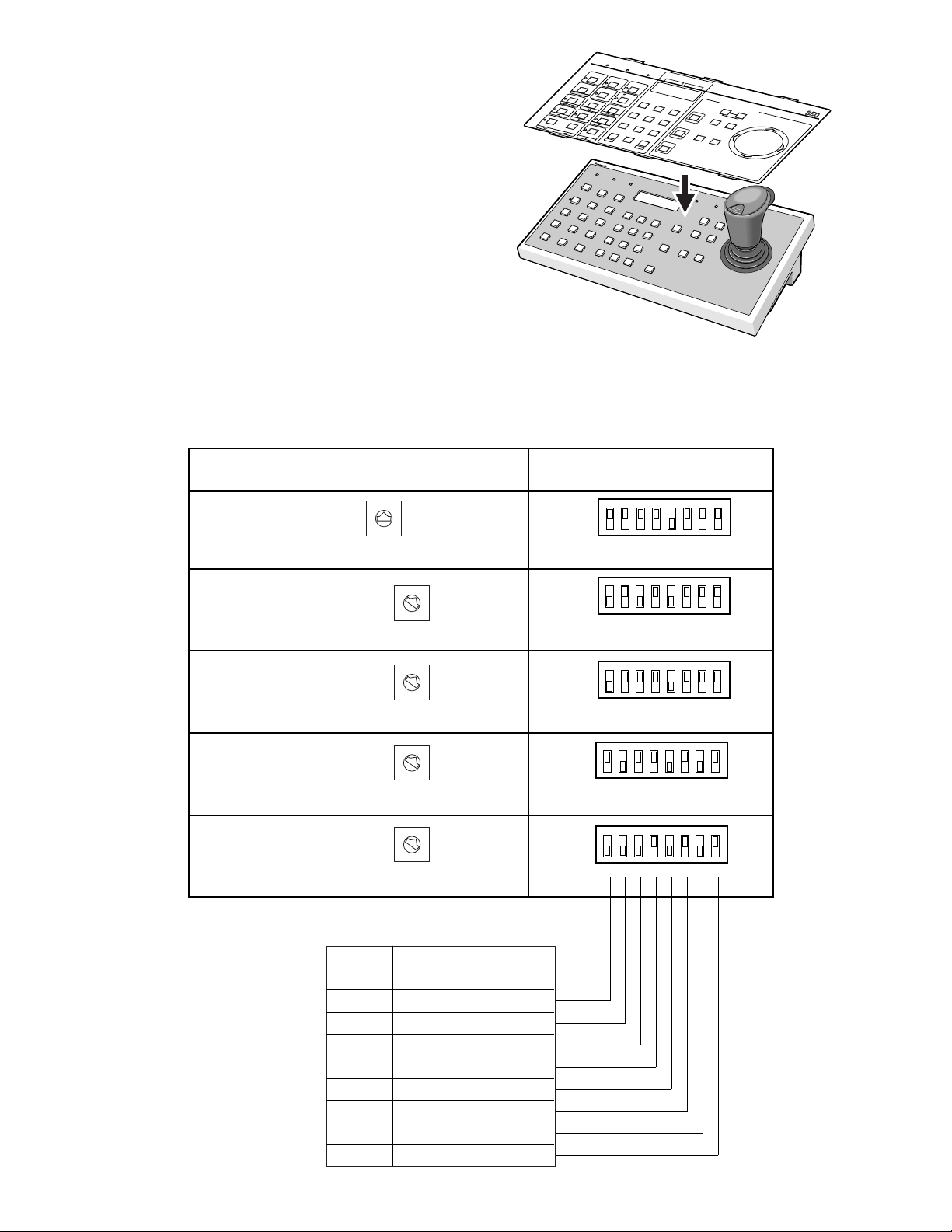
■ Rear Panel Switch Setting (Summary)
An 8-bit DIP switch and a rotary switch mounted on the rear of the controller specify the operation mode and parameters for
communication. Switch settings depend on your system configuration. A summary of switch positions is shown below. For
detailed information refer to the description of switch settings provided for each system.
MODE
1 2345678
OFF
ON
0
9
8
7
6
5
4
3
2
1
CONTROLLER No.
System
Controller No. SW
MODE DIP SW
PS•Data
MODE
1
2345678
OFF
ON
WJ-FS616C
MODE
1 2345678
OFF
ON
CONTROLLER No.
WJ-FS616
MODE
1 2345678
OFF
ON
MODE
1 2345678
ON
CONTROLLER No.
System 850
WJ-SX850
WJ-SX150
0
9
8
7
6
5
4
3
2
1
CONTROLLER No.
#1
#1
#1
0
9
8
7
6
5
4
3
2
1
CONTROLLER No.
#1
0
9
8
7
6
5
4
3
2
1
0
9
8
7
6
5
4
3
2
1
See page 16
Function
Bit 3
Bit 2
Bit 1
Bit 4
Bit 5
Bit 6
Bit 7
Bit 8
Operation mode
Operation mode
Operation mode
Reserved
Line termination
Administrator mode
Baud rate selection
Data transmission mode
ON
T/L MODE
FUNCTION
CAMERA SET
OPERATE
LOCK
AL
ALT
ALM RESET
S
E
Q
ALL
RESET
A
LM
SU
S
P
E
N
D
EL-ZO
OM
PRE-POSI
STILL
SET UP
OFF
ON/OFF
ARM
MULTI
SCR
EEN
U
E
N
C
E
CAM
M
U
L
T
I S
EL
E
C
T
U
N
IT
ESC
4
7
8
0
UNIT
SPOT
VTR
SET
1
2
5
9
CAMERA
S
ystem Controller
CA
MERA SITE CONTRIL
CLOSE OPEN
IR
IS
AU
TO/+
IRIS RESET
FOCUS
NEAR FAR
AUX 2
HOME/-
TELE
AUX 1
CAM
3
6
ZOOM
AUTO
FOCUS
WIDE
WV
-
For Multiplexer
CU CJ
Page 8

9
For Panasonic Security Data (PS•Data) Systems
Page 9
10
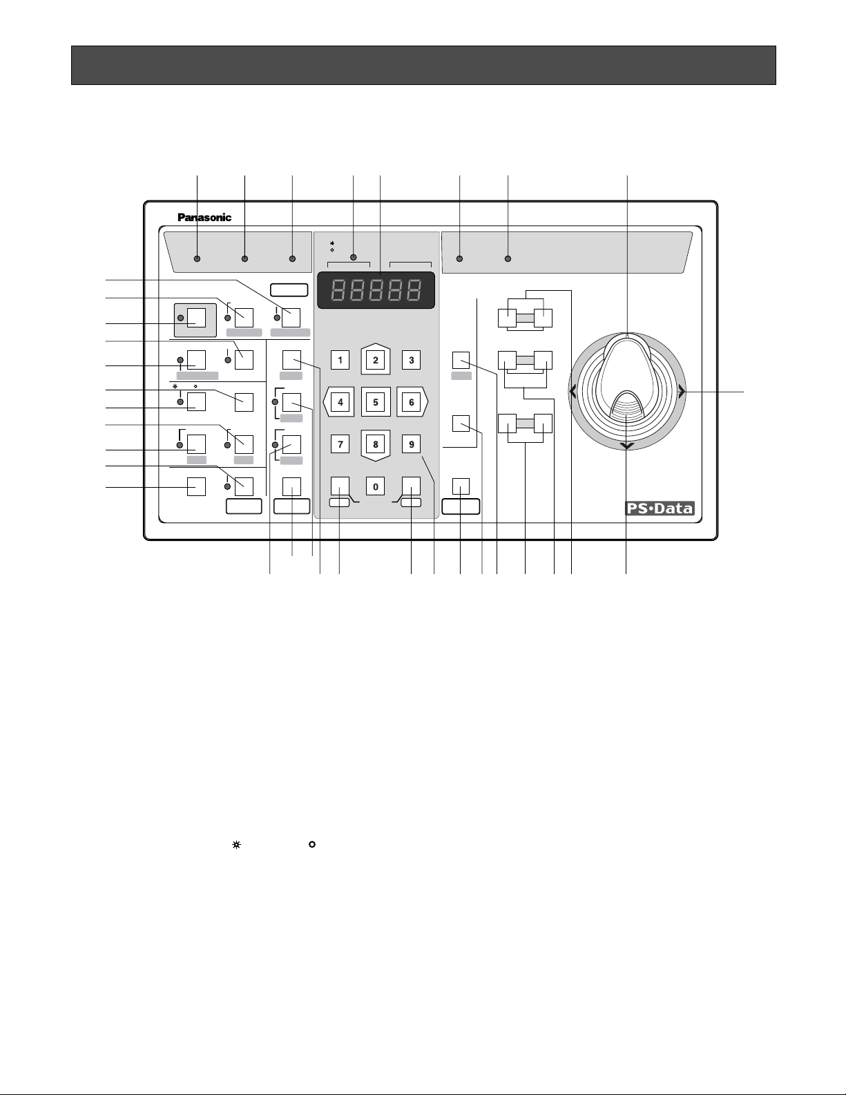
MAJOR OPERATING CONTROLS & THEIR FUNCTIONS
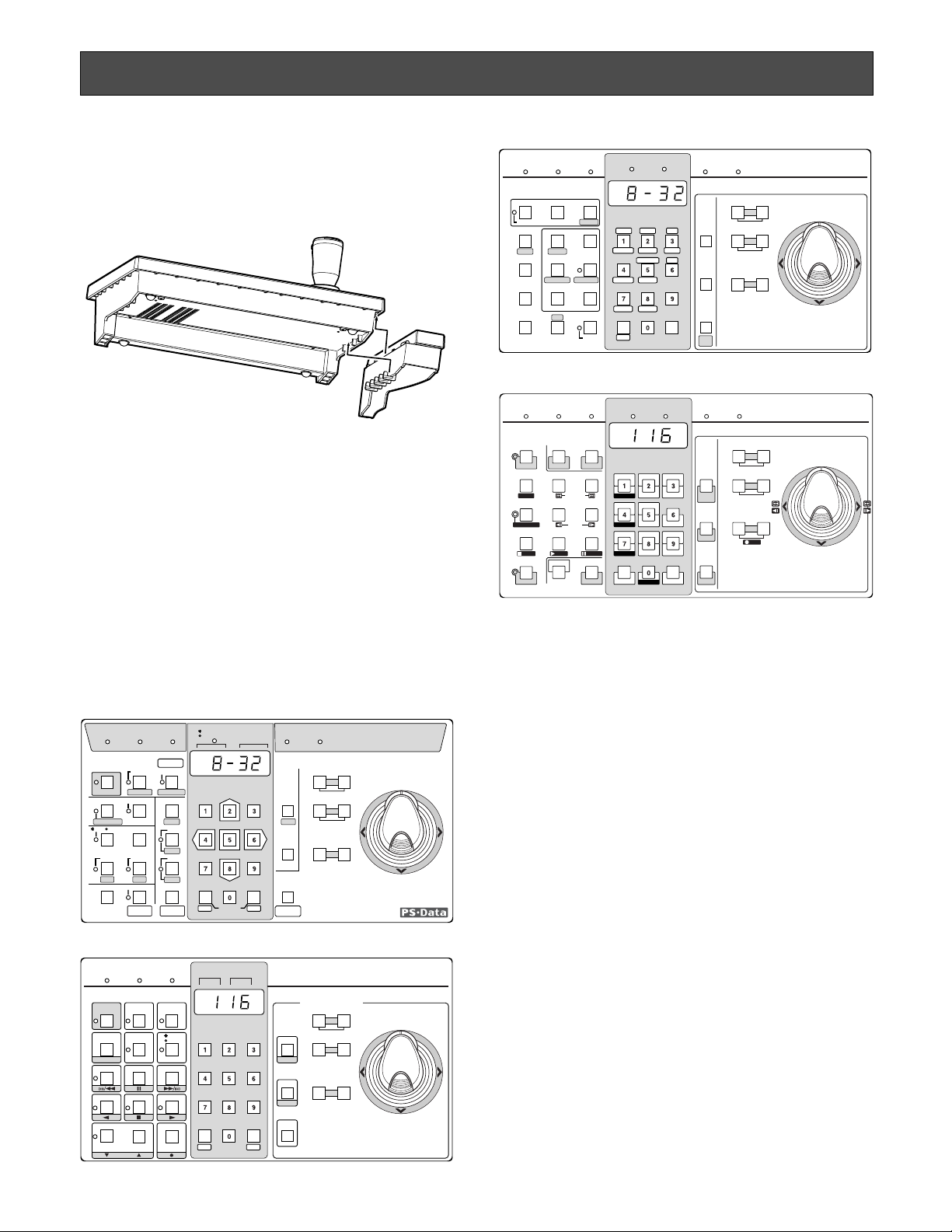
■ Front View (Template for PS•Data)
q Operate indicator (OPERATE)
Is lit while power is supplied to the System Controller.
w Login indicator (LOGIN)
Lights up when communication is established with
PS
•
Data compatible system units.
e Alarm indicator (ALARM)
Blinks when an alarm is activated.
Blinking changes to steady light when the alarm is automatically reset.
To turn the indicator off, press the Alarm Reset button.
r Monitor/Unit indicator ( MONITOR/ UNIT)
When this indicator lights up, the monitor number is displayed. When it goes off, the unit address is displayed.
t LED Display
LED display allowing you to confirm the monitor or unit
number and the number of the currently controlled
camera.
It also displays numeric input, error status, etc.
The monitor or unit number is displayed when initial
communication is established.
y Busy indicator (BUSY)
Lights up when you attempt to control a system unit or
camera that is already used by a higher priority operator, or when a higher priority operator selects the camera or system unit you are currently operating.
Operations from the System Controller are disabled
until this indicator goes off.
u Prohibited indicator (PROHIBITED)
Lights up when an attempt is made to access a function
that is prohibited to the operator level.
i Zoom Wheel Controller
This control is used for zooming cameras equipped
with the specified lens. Moving the control to the right
will zoom in the image. Moving the control to the left will
zoom out the image.
OPERATE LOGIN ALARM
CAM SETUP
PROGRAM
PROGRAM
PRESET
UNIT A
IRIS
CLOSE OPEN
NEAR FAR
WIDE TELE
FOCUS
ZOOM
AUTO FOCUS
IRIS RESET
AUTO
SETUP
ALM SUSPEND
FUNCTION
CAM FUNCTION
MULTI SCREEN SELECT
DEF
WIPER
EL-ZOOM
SHIFT
ALM RESET
VCR CAM
STILL
–
+
ALM RECALL
PATROL
LEARN
PATROL
STOP
AUX 1
AUX 2
B/W UNIT
SEQ PAUSE
SLOW
SEQUENCE
PATROL PLAY
HOME/PRESET
UNIT B
MON
CAM
LOGOUT
ESC SET
BUSY PROHIBITED
MONITOR
UNIT
CAMERA
System Controller
WV-CU CJ
360
@8
@7
@2
@0
@1
@9
#2
#1
#0
wqertyu i
o
!3 !0!2 !1!6!7!8!9@5
@6
!5!4@3
@4
#4
#3
Page 10

11
o Joystick Controller
Used to manually operate the pan/tilt head, or move the
cursor in the setup menu on the active monitor screen.
The joystick can also be moved in 8 directions.
Holding down the joystick in the desired position will
keep the cursor moving continuously in the setup menu.
(See page 17.)
}: Upward
{: Downward
]: Left
[: Right
!0 Top button
Pressing this button will automatically set the lens focus
of a specified camera.
!1 Iris buttons (IRIS, CLOSE/OPEN)
Close or open the lens iris of cameras equipped with
the specified lens.
When these buttons are pressed simultaneously, the
lens iris is reset to the factory default setting.
!2 Focus buttons (FOCUS, NEAR/FAR)
Adjust the lens focus of cameras equipped with the
specified lens.
When these buttons are pressed simultaneously, the
lens focus is set automatically if the specified camera is
used.
!3 Zoom buttons (ZOOM, WIDE/TELE)
Zoom the image in or out if the camera is equipped with
the specified lens.
!4 Unit A/UNIT button (UNIT A/UNIT)
Selects a specific system unit in a multiple unit system.
To select a unit, press this button after entering the unit
number with the numeric button. To confirm a unit number, press this button after pressing the SHIFT button.
The selected unit address appears on the LED display.
The unit that is assigned to number 1 can be selected
by pressing this button.
!5 Unit B button (UNIT B)
Selects a specific system unit in a multiple unit system.
To select a unit, press this button after entered the unit
number with the numeric button. The selected unit
address appears on the LED display.
Just pressing this button will select the system unit
assigned the number 1.
!6 Home/Preset/Program Preset button
(HOME/PRESET/PROGRAM PRESET)
Returns a specific camera to its home position.
In combination with the numeric buttons, this button is
also used to recall a preset position assigned to a specific camera.
Pressing it while holding down the Program/Camera
Setup/Camera Function button will program the preset
position.
!7 Numeric buttons (0-9)
These buttons are used for numeric input, such as camera, monitor and unit numbers, and preset positions.
!8 Camera/Set button (CAM/SET)
CAM: Used for camera selection. To select a camera,
enter the desired camera number with the numeric
buttons, and then press this button.
SET: Executes the currently highlighted setting in the
setup menu.
Pressing this button together with the MON/ESC button
for approximately 2 seconds will log out from the system.
!9 Monitor/Escape button (MON/ESC)
MON: Used for monitor selection and confirmation. To
select a monitor, enter the desired monitor number
with the numeric buttons, and then press this but-
ton. The selected monitor number appears on the
LED display.
To confirm a monitor number, simply press this but-
ton.
ESC: Used to escape from the currently highlighted
selection and return to the previous menu of the
setup menu.
Pressing this button together with the CAM/SET button
for approximately 2 seconds will log out from the system.
@0 Program/Camera Setup/Camera Function button
(PROGRAM/CAM SETUP/CAM FUNCTION)
Programs camera patrol learning and preset position
functions.
Pressing this button for 2 seconds or more will open the
camera setup menu. Pressing it in combination with the
numeric buttons after pressing the shift button will execute camera functions.
The LED next to the button is lit during the camera
setup operation.
@1 Setup/Function button (SETUP/FUNCTION)
Pressing this button for 2 seconds or more will open the
setup menu of a system unit.
When the SHIFT indicator is lit, it provides access to the
functions of the system unit. Enter a function number
with the numeric keys, then press this button.
The LED next to the button is lit during the setup operation.
@2 Shift button (SHIFT)
Shifts the button function between the normal and the
shift mode shown in half-tone print under the button on
the template. The LED next to the button is lit in the
shift mode.
@3 Auto Panning/Black and White button (AUTO/B/W)
Activates the auto panning function of cameras provided with this feature. Pressing this button in the shift
mode will change the camera picture from colour to
black and white for better viewing in a dark place.
Page 11

12
AUTO PAN ON or combination camera function:
Simply press this button, or press numeric button 1
followed by this button.
AUTO SORT ON: Press numeric button 2 followed by
this button.
AUTO SEQ ON: Press numeric button 3 followed by
this button.
RANDOM PAN ON: Press numeric button 4 followed by
this button.
@4 Defroster/Auxiliary 2 button (DEF/AUX 2)
Activates the housing defroster of cameras provided
with this feature. Pressing this button in the shift mode
will turn on the AUX 2 function controlling accessories
connected to the cameras or the system.
The LED next to the button is lit while the defroster or
AUX 2 function operates.
@5 Wiper/Auxiliary 1 button (WIPER/AUX 1)
Activates the housing wiper of cameras provided with
this feature. Pressing this button in the shift mode will
turn on the AUX 1 function controlling accessories connected to the cameras or the system.
The LED next to the button is lit while the wiper or AUX
1 function operates.
@6 Patrol Play/Patrol Learn button (PATROL PLAY/
PATROL LEARN)
Starts the camera patrol play. While holding down the
Program/Camera setup/Camera Function button, pressing this button will start to program the camera patrol
learning.
@7 Alarm Suspend button (ALM SUSPEND)
Suspends or allows the alarm process.
The LED next to the button is lit while the alarm suspension mode operates.
@8 Alarm Reset/Alarm Recall button (ALM RESET/ALM
RECALL)
Resets system alarm when the alarm function is active.
Pressing this button in the SHIFT mode will recall the
alarm logs (record of alarms activated in the past).
Select a monitor, and then press this button to display
the alarm logs on the monitor screen. Pressing this button after pressing the shift button again will cancel the
function.
The LED next to the button is lit while Alarm Recall
mode is activated.
@9 Multiscreen Selection button (MULTI SCREEN
SELECT)
Selects the number of segments into which the multiscreen is split on the selected monitor connected to the
MULTISCREEN OUT terminal of the Video Multiplexer.
#0 VTR/Camera Selection button ( VCR/ CAM)
Changes the display on the multiscreen monitor
between the live picture of a camera and the playback
picture of a recording device. The LED next to the button is lit while VCR is selected.
#1 Electronic Zoom/Increment button (EL-ZOOM/+)
Zooms the camera picture or VCR playback picture displayed on the multiscreen monitor.
Pressing this button in the shift mode will move the
camera sequence one step forward from the step previously paused while a system unit provided with SEQ
PAUSE (e.g., a Video Multiplexer) is selected.
Pressing this button in the shift mode will select the picture of camera with the next higher number for display
on the monitor while a system unit connected with cameras (e.g., a Data Multiplex Unit) is selected.
The LED next to the button is lit while Electronic Zoom
mode is selected.
#2 Still/Decrement button (STILL/–)
Freezes the camera picture or VCR playback picture on
the multiscreen monitor.
Pressing this button in the shift mode will move the
camera sequence one step backward from the step
previously paused while a system unit (e.g., a Video
Multiplexer) provided with SEQ PAUSE is selected.
Pressing this button in the shift mode will select the picture of the camera with the next lower number for display on the monitor while a system unit connected with
cameras (e.g., a Data Multiplex Unit) is selected.
The LED next to the button is lit while a still picture is
displayed.
#3 Sequence/Patrol Stop button (SEQUENCE/PATROL
STOP)
Runs or stops a preset sequence in which a series of
camera pictures is displayed in succession on the monitor screen for the specified duration. Pressing it while
holding down the Program/Camera Setup/Camera
Function button will stop programming of camera patrol
learning.
The LED next to the button is lit while a sequence runs.
#4 Sequence Pause/Slow button (SEQ PAUSE/SLOW)
Pauses a sequence running on the selected monitor. In
this mode, a series of camera pictures is displayed in
pause on the monitor screen for the specified duration.
Pressing this button while moving the joystick controller
will decrease the pan/tilt speed.
Page 12
13
INSTALLA TIONS (PS•Data)
The installation should be made by qualified service personnel or system installers according to the following instructions.
CAUTION
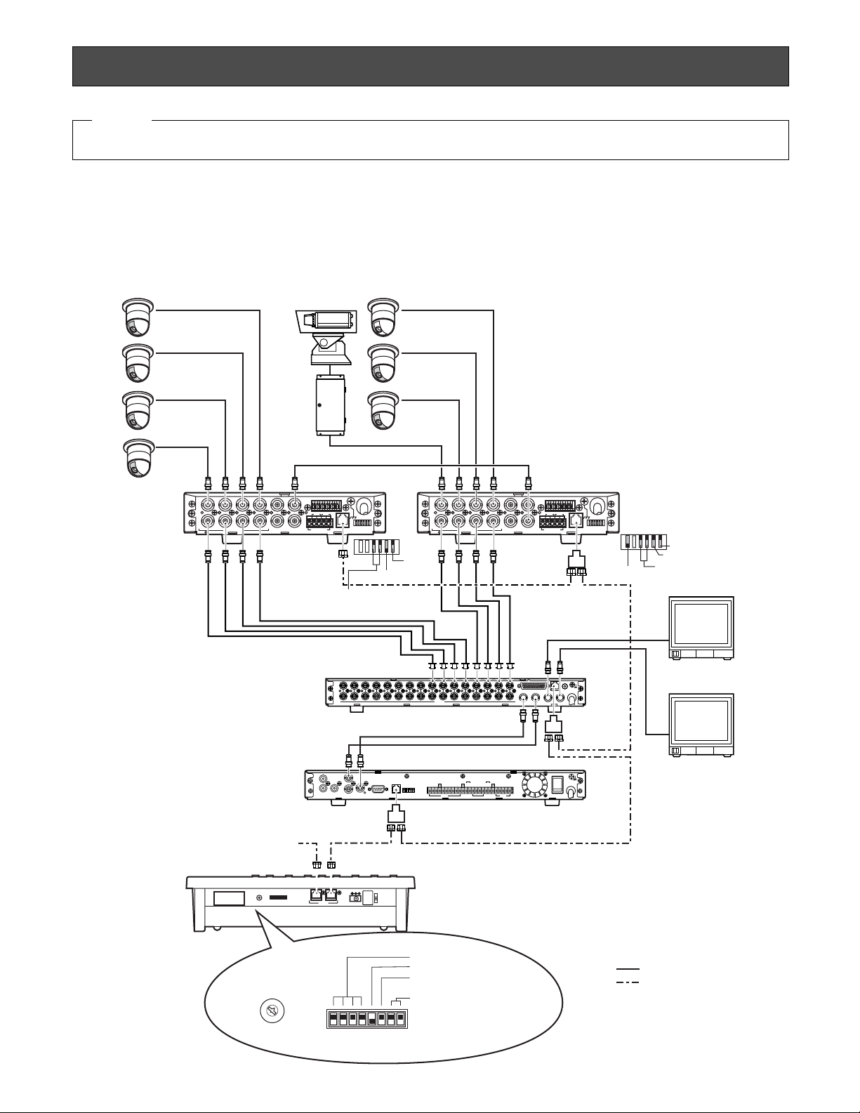
■ System Connections
● Connection Example
Example 1 shows 8 cameras connected to 2 Data Multiplex Units (WJ-MP204C), to a Video Multiplexer (e.g., WJ-FS416) and a
Digital Disk Recorder (e.g., WJ-HD100). The WV-CU360CJ controls these system units through RS-485 communication while
pictures are viewed on the monitors.
SIGNAL
GND
ALARM/REMOTE
OUT
IN
VIDEO
16 15 14 13 12 11 10 9 8
16 15 14 13 12 11 10 9 8
7654 21
76543321
PLAY IN
REC OUT
SPOT OUT
DATA
CAMERA
SW IN
MULTI
SCREEN OUT
SD RD
IN IN
CAMERA RS485
ABABG
VS/VDSPOT DATA
ALARM / REMOTE
MODE
SIGNAL GND
4321
OUT OUTINOUT
4321
TR
IN IN
CAMERA RS485
ABABG
VS/VDSPOT DATA
ALARM / REMOTE
MODE
SIGNAL GND
4321
OUT OUTINOUT
4321
Camera No. 1
Camera No. 2
Camera No. 3
Camera No. 4
Camera No. 5
Camera No. 6
Camera No. 7
Camera No. 8
VS/VD INPUT
Unit Address 1Unit Address 2
WJ-MP204C
WJ-MP204C
WJ-FS416
WJ-HD100
Unit Address 3
Unit Address 4
Video Signal
6-conductor Modular Cable (supplied)
Termination ON
MODE
VS/VD OUTPUT
4-Line
Monitor No. 1
Monitor No. 2
Panasonic Security
Data mode
Termination OFF
Panasonic Security
Data mode
4-Line
MODE
VD OUT
RS-485 Signal
(Panasonic Security
Data Mode)
SIGNAL GND
ALARM
SERIES
RECORD
TIME
ADJUST
REMOTE
MODEDATARS-232CVIDEO
OUT
IN
OUT
IN
AUDIO
MONITOR OUT
(PLAY)
CAMERA
SW OUT
G
G
G
POWER
ON
OFF
JOG-CLICK
JOG-LEFT
JOG-RIGHT
ALARM SEARCH
STEP
REW/FF
STOP/SETUP
PLAY
REC
OUT
PLAY OUT
REC OUT
AUTO OFF OUT
DISK END OUTINOUTINRECALL
(EXT REC)
OUT
RECOVER OUT
RESET IN
IN
PLAY INPLAY
VIDEO IN REC OUT
RS-485 Cable
Branch
Cable
Up to four WV-CU360CJ
can be used in a system.
DC 9V IN
DATAMODECONTROLLER No.
0
9
8
7
6
5
4
3
2
1
0
9
8
7
6
5
4
3
2
1
Keep in OFF position
Keep in OFF position
Termination ON
Set to OFF position
(for operator mode)
Controller No. 1
Refer to DIP switch setting on page 15
CONTROLLER No.
Page 13
14
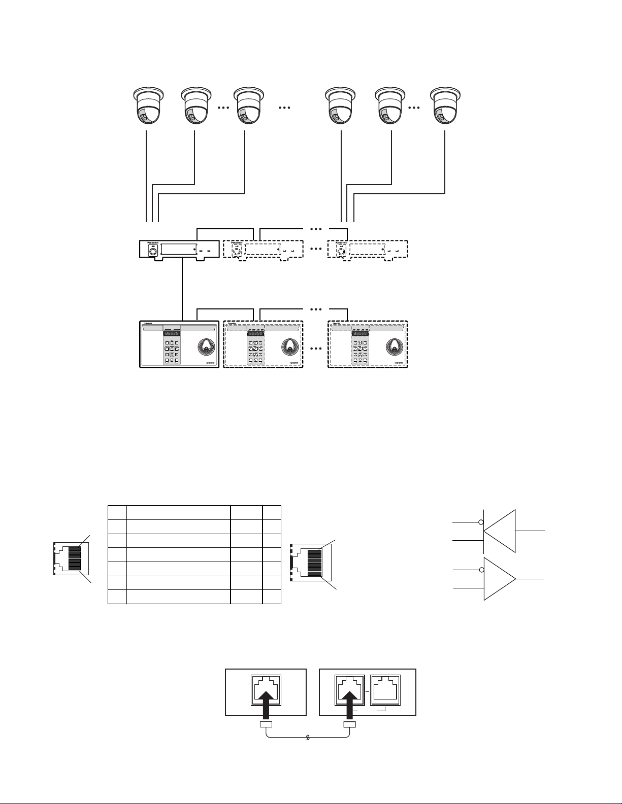
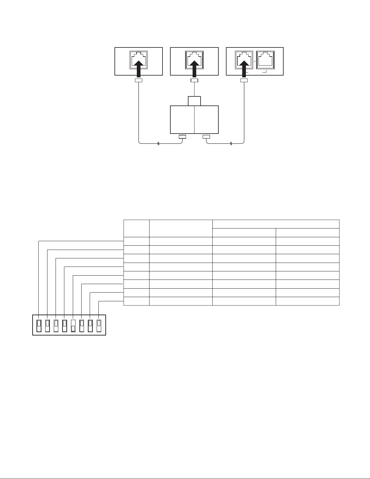
● DA TA Port Connection (PS•Data)
Data ports are connected with RS-485 cables among devices using the PS•Data protocol as follows.
Note: When using cables other than those supplied, make sure to use shielded 4-wire twisted pair cable suitable for RS-485
communication.
• Internal Diagram
• Basic Connection
Example 2 shows 4 Data Multiplex Units connected with 16 combination cameras, and 4 System Controllers.
System Controller
WV-CU CJ
360
Data Multiplex Unit WJ-MP204C Data Multiplex Unit WJ-MP204 Data Multiplex Unit WJ-MP204
WJ-MP204C
WV-CU360CJ
4 cameras can be connected to one Data Multiplex Unit
System Controller
WV-CU CJ
360
System Controller
WV-CU CJ
360
Up to 4 Data Multiplex Units
Up to 4 System Controllers
Channel 1 Channel 2 Channel 4 Channel 13 Channel 14 Channel 16
Unit
address 1
Controller
No. 1
Controller No. 2 Controller No. 4
Unit
address 2
Unit
address 4
See page 16 for MODE switch and
CONTROLLER NO. switch settings.
No. No.
1 1
1
6
WJ-MP204C ← WV-CU360CJ
2 2
WJ-MP204C ← WV-CU360CJ
3 3
WJ-MP204C → WV-CU360CJ
4 4
WJ-MP204C → WV-CU360CJ
5 5
6 6
Data Flow
–
–
Name
GND
TX(B)
TX(A)
RX(B)
RX(A)
GND
Controller end
TX (B)
1
TX (A)
RX (B)
6
RX (A)
Data Multiplex Unit
WJ-MP204C
Termination:
DATA
ON
RS-485 Cable
System Controller
WV-CU360CJ
DATA
Termination:
ON
Page 14
15
SW position
• Daisy Chain Connection
■ DIP Switch Setting (PS•Data)
An 8-bit DIP switch mounted on the rear panel specifies the communication mode, etc. The default position is marked with an
asterisk *.
OFF
Not used
Function
ON
Bit 3
Bit 2
Bit 1
Bit 4
Bit 5
Bit 6
Bit 7
Bit 8
Operation mode
Operation mode
Operation mode
Reserved
Line termination
Administrator mode
Baud rate selection
Data transmission mode
Fixed to OFF*
Fixed to OFF*
Fixed to OFF*
Fixed to OFF*
Off
Off*
Fixed to OFF*
Fixed to OFF*
Not used
Not used
Not used
Not used
On*
On
Not used
1. Remove the DC plug from the rear of the controller.
2. Set the switch referring to the table.
3. Connect the DC plug to the controller.
Notes:
• Bit 4 is reserved.
• Bit 5 opens or terminates the communication chain. The switch should be set to OFF when the controller is located in an
intermediate position.
• Bit 6 specifies the operation mode, Operator or Administrator. The switch should be set to ON when setting up the controller. Remember to set this switch to the OFF position after completion of the setup operation.
• Bits 7 and 8 are used in the OFF position.
Video Multiplexer
WJ-FS416
Termination:
ON
RS-485
Cable
Data Multiplex Unit
WJ-MP204C
Termination:
OFF
DATA
Branch
Cable
System Controller
WV-CU360CJ
DATA DATA
Termination:
ON
RS-485
Cable
12345678
OFF
ON
MODE
Page 15

16
● MODE Switch Setting for System Example 2
The MODE switch needs to be set prior to operating a system connected as shown in Example 2.
Bit 3 should be set to OFF.
Bit 5 should be set to OFF when the controller is placed
in an intermediate position, or set to ON when it is connected at the chain end.
■ Controller Number Setting (PS•Data)
A 10-position rotary switches provided on the rear for specifying the unit number of the WV-CU360CJ controller in a
PS
•
Data system.
1. Remove the DC plug from the rear of the controller.
2. Use a screw driver to rotate the switch so that the arrow
comes to the number you wish.
3. Connect the DC plug to the controller.
Notes:
• Set the switch to #1 when a single controller is used in
the system.
• Specify a unique number for each controller when connecting multiple controllers in the system. One controller within the multiple controller system must be
assigned the number 1.
• Positions #0 and #9 are reserved and cannot be used.
Controller No. Switch of WV-CU360CJ Controller No.
0 Reserved
11
22
33
44
55
66
77
88
9 Reserved
OFF
ON
12345678
0
1
9
2
8
3
7
4
6
5
CONTROLLER No.
Page 16
17
CONTROLLER SETUP PROCEDURES (PS
•
Data)
To display the setup menus for the WV-CU360CJ System Controller on the LED display, set the MODE switch and power up
the controller as described below.
■ Prior to Setup
Do the following before entering the setup mode.
1. Confirm that all necessary connections and switch settings are complete.
2. With the power turned off, move bit #6 of the MODE
switch on the rear to ON position.
3. Supply power to the controller.
4. Turn on the power of cameras and other system units.
5. The LCD displays [SEtUP]. The controller is ready to
enter the setup mode.
When setup is completed, restore the switch to its original
position.
1. With the power turned off, move bit #6 of the MODE
switch on the rear to OFF position.
2. Supply power to the controller.
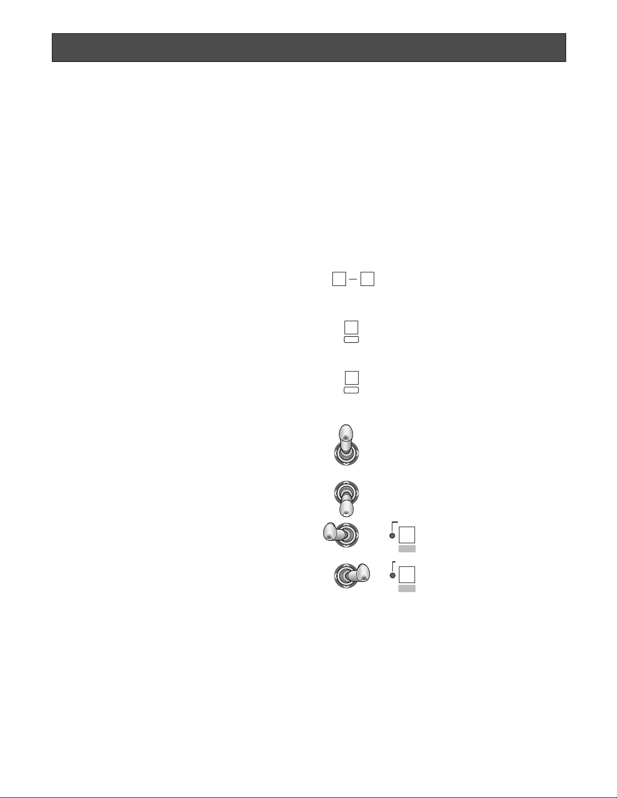
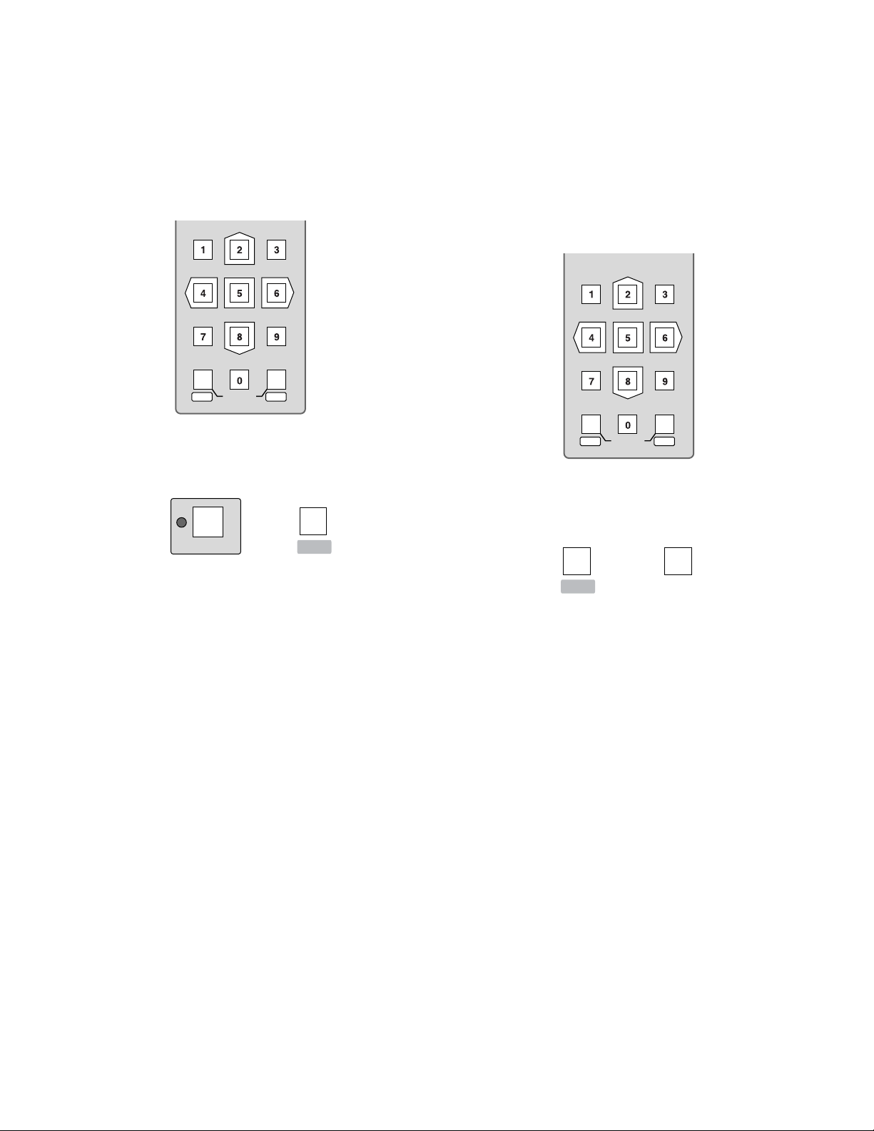
■ Buttons and Controls Used for Setup
The following buttons and joystick operations are used in
the setup operation. There are three ways to select a parameter, but the following pages only describe the selection
by use of the joystick. Instead of operating the joystick, you
can enter the number enclosed in brackets with the numeric keys or press the plus and minus buttons.
0
9
Numeric buttons: To select a parameter
To enter a password or
parameter
CAM/SET button: To confirm the selected
menu, selected parameter or entered password
To enter a submenu
MON/ESC button: To return to the previous
menu
CAM
SET
MON
ESC
Up: To select a setup menu
Down: To select a setup menu
Left: To decrease the parameter
Right: To increase the parameter
EL-ZOOM
STILL
–
+
or
or
Page 17
18
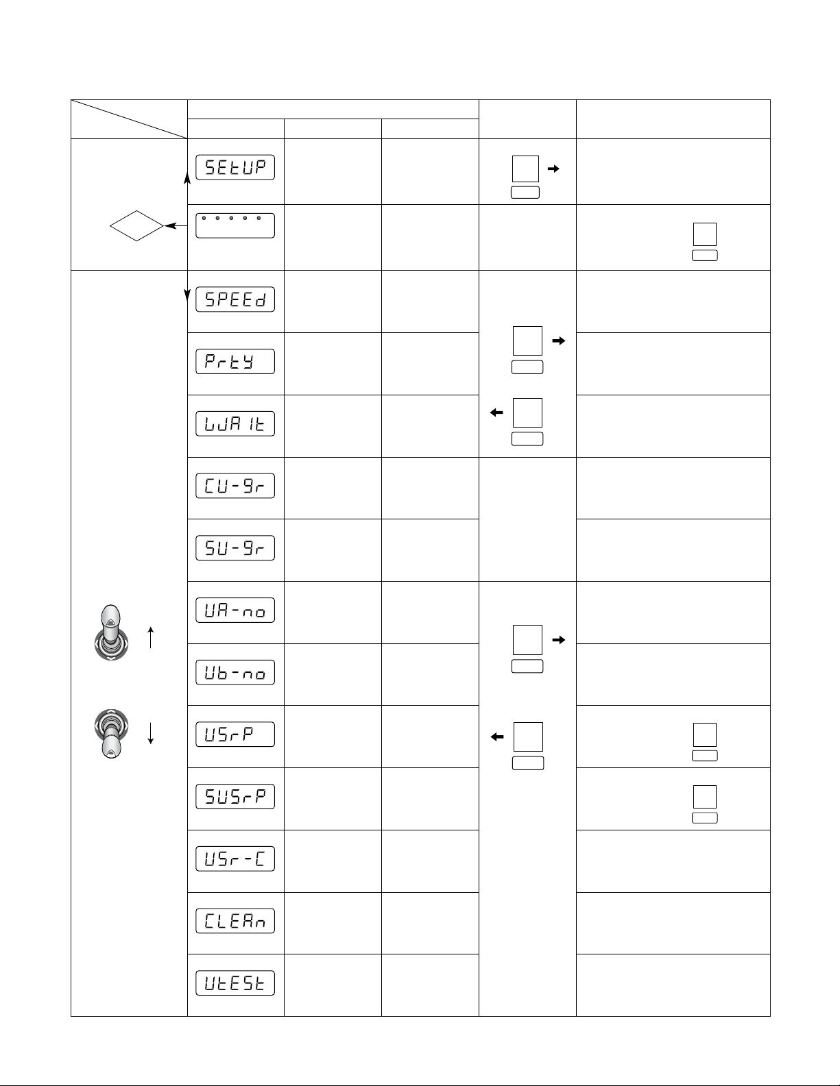
■ Setup Menus
There are 12 setup menus as shown below.
Menu
Selection
Move Joystick up
and down to select
Setup Menus
Parameter Selection (default*)
LED Display
blinking
Setup
Administrator
Password
Prompt
Speed
Parity
Wait
Controller
Unit
Group
System
Unit
Group
Unit A
Number
Unit B
Number
User
Password
Super
User
Password
User
Certification
Cleaning
Unit
Test
Initial
Display
Authorization
Baud Rate
(bps)
Press
twice
Parity Check
Wait Time
(ms)
Unit
Assignment to
Button A
Unit
Assignment to
Button B
Administrator
Password
User
Authorization
Camera
Cleaning
Unit Connection
Test
CAM
SET
CAM
SET
MON
ESC
CAM
SET
LED prompts you to enter a password
Enter a 5-digit
password, press
(12345*)
(1) 2 400 (2) 4 800 (3) 9 600*
(4) 19 200
(1) None* (2) Even
(1) Off* (2) 100 (3) 200 (4) 400
(5) 1 000
Leave as it is
Leave as it is
Enter a 5-digit
number, press
(12345*)
Reading Function
OK
No
CAM
SET
CAM
SET
Enter a 5-digit
number, press
(12345*)
(1) Off (2) On*
CAM
SET
MON
ESC
Page 18

19
● Administrator Authorization
1. Press the CAM/SET button while [SEtUP] is displayed.
The [- - - - -] prompt appears.
2. Enter a password with the numeric buttons, then press
the CAM/SET button.
The default setting is [12345].
3. [SPEED] appears when the right password is entered. If
password entry failed, the menu returns to [- - - - -].
Notes:
• We recommend that you register a new password different from “12345” in [SUSrP], and note down the registered password for future reference.
• Powering up the controller while holding down numeric
buttons 2, 4 and 5 simultaneously will reset the password to “12345”. Remember that this procedure also
resets all other menu parameters to the default settings.
● Baud Rate
In this menu, the communication speed (bps: bits per second) is selected. The communication speed should match
that of the other units connected in the communication
chain.
1. Display [SPEED] and press the CAM/SET button twice.
2. Select a parameter entering a bracket-enclosed number, e.g., (3), moving the joystick right and left, or
pressing the [+] and [–] button.
The default setting is 19 200 bps.
(1) 2 400: 2 400 bps
(2) 4 800: 4 800 bps
(3) 9 600: 9 600 bps
(4) 19 200: 19 200 bps
Note: Selecting a slower rate (e.g., 2 400 bps) will
delay the response time (e.g., the time until an activated alarm is reset).
3. Press the CAM/SET button to validate the selection.
4. Press the ESC button to go back to the previous menu.
● Parity
In this menu, the parity check mode is selected.
1. Display [PrtY] and press the CAM/SET button twice.
2. Select a parameter with the joystick.
The default setting is None.
n: None
E: Even parity
3. Press the CAM/SET button to validate the selection.
4. Press the ESC button to go back to the previous menu.
● Wait Time
In this menu a wait time is selected. The controller will
retransmit data when there is no response during the specified wait time.
1. Display [LJAit] and press the CAM/SET button twice.
2. Select a parameter with the joystick.
The default setting is Off.
(1) OFF: Off, no retransmission of data
(2) 100: 100 ms
(3) 200: 200 ms
(4) 400: 400 ms
(5) 500: 500 ms
(6) 1 000: 1 s
3. Press the CAM/SET button to validate the selection.
4. Press the ESC button to go back to the previous menu.
The following two menus should be maintained in the
default condition.
● Controller Unit-Group Address
[CU-gr] appears on the Setup menu, but leave the
default as it is.
● System Unit-Group Address
[SU-gr] appears on the Setup menu, but leave the
default as it is.
Page 19

20
● Unit A button Assignment
In this menu, a maximum of 9 system units is assigned to
numeric buttons 1-9 regardless of unit address.
This is to avoid double-digit unit addresses which can
occur in a large system with many units connected and
could confuse operators.
A frequently used system unit can be easily selected in normal operation by pressing one numeric button and then the
UNIT A button.
1. Display [UA-no] and press the CAM/SET button. The
LED displays [A1-01] while “1” following A blinks.
The first 2 digits from A1 to A9, “A numbers”, stand for
numeric buttons from 1 to 9 to be pressed prior to UNIT
A button in normal operation. The next 2 digits are the
unit address assigned in the following procedures.
The default setting is shown below.
A1-01
A2-02
A3-03
A1-04
A5-05
A6-06
A7-07
A8-08
A9-09
2. Select an “A number” entering a number from 1 to 9,
then press the CAM/SET button. The LED displays “A
number” A3 when numeric button 3 is entered for
example.
Available A numbers: 1-9
3. Press the CAM/SET button to validate the selection. The
LED displays [A3-03] while the next two digits are blinking.
4. Enter a 2-digit unit address that you wish to assign to
the “A number” (e.g., A3), then press the CAM/SET button. The LED displays [A3-99], for example, when you
enter unit address 99.
Available addresses: 01-99
5. Press the CAM/SET button to validate the selection.
Repeat above the steps 2 to 5 as needed.
6. Press the ESC button to go back to the previous menu.
● Unit B button Assignment
The UNIT B button is set up in the same way as the UNIT A
button for use in normal operation. Refer to the above
description for Unit A button Assignment.
● User Password
In this menu, a 5-digit password for user authorization is
registered.
1. Display [UsrP ] and press the CAM/SET button. The
LED displays the registered password.
2. Enter a 5-digit password with the numeric buttons.
The default setting is [12345].
Available password digits: 00000-99999
3. Press the CAM/SET button to validate the selection.
4. Press the ESC button to go back to the previous menu.
● Administrator Password
In this menu, a 5-digit password for administrator certification is registered.
1. Display [SUsrP] and press the CAM/SET button. The
LED displays the registered password.
2. Enter a 5-digit password with the numeric buttons.
The default setting is [12345].
Available password digits: 00000-99999
3. Press the CAM/SET button to validate the selection.
4. Press the ESC button to go back to the previous menu.
● User Password Certification
In this menu, password certification in normal operation is
enabled or disabled.
1. Display [USr-C] and press the CAM/SET button. The
LED displays [UC-on] or [UC-oF].
2. Select On or Off with the joystick controller.
The default setting is On.
on: Password certification enabled.
oF: Auto log-in
3. Press the CAM/SET button to confirm the selection.
4. Press the ESC button to go back to the previous menu.
Page 20

21
● Camera Cleaning
This menu is for specifying the order in which combination
cameras connected to the system are cleaned.
The camera cleaning function causes cleaning of the builtin slip rings that conduct electric signals while moving the
pan/tilt head. All combination cameras connected to the
system are cleaned in the order specified here. Picture
viewing is disabled during the cleaning process.
1. Display [CLEAn] and press the CAM/SET button. The
LED displays [no-01].
2. Use the numeric buttons to enter the number of the
camera where cleaning is to start.
The default setting is no-01.
Available camera numbers: 01-199
3. Press the CAM/SET button to start cleaning.
Two animated digits appear in the left part of the LCD
while the digits at right display the number of the camera being cleaned.
When cleaning is finished, the number of the last camera cleaned is displayed without animation.
4. Press the ESC button to go back to the previous menu.
● Unit Connection T est
This menu is for specifying the order in which data communication between system units is tested prior to operating
the system as a whole.
1. Display [UtESt] and press the CAM/SET button. The
LED displays [01-on] or [01-oF].
2. Enter the 2-digit unit number you wish to start with.
3. Press the CAM/SET button to start the test.
The digits in the left part of the LCD display the unit
number under test while 2 animated digits appear at
right.
To stop the test in progress, press the CAM/SET button.
When testing is finished, the number of the last unit tested is displayed without animation.
4. Press the CAM/SET button. Enter a 2-digit number(e.g.,
01), then press the CAM/SET button.
You can now confirm the test results of a specific unit.
When Off is displayed, check connections, switch settings, etc., of the system unit.
01-on: On, unit 01 is connected.
01-oF: Off, unit 01 is disconnected.
5. Press the ESC button to go back to the previous menu.
Page 21
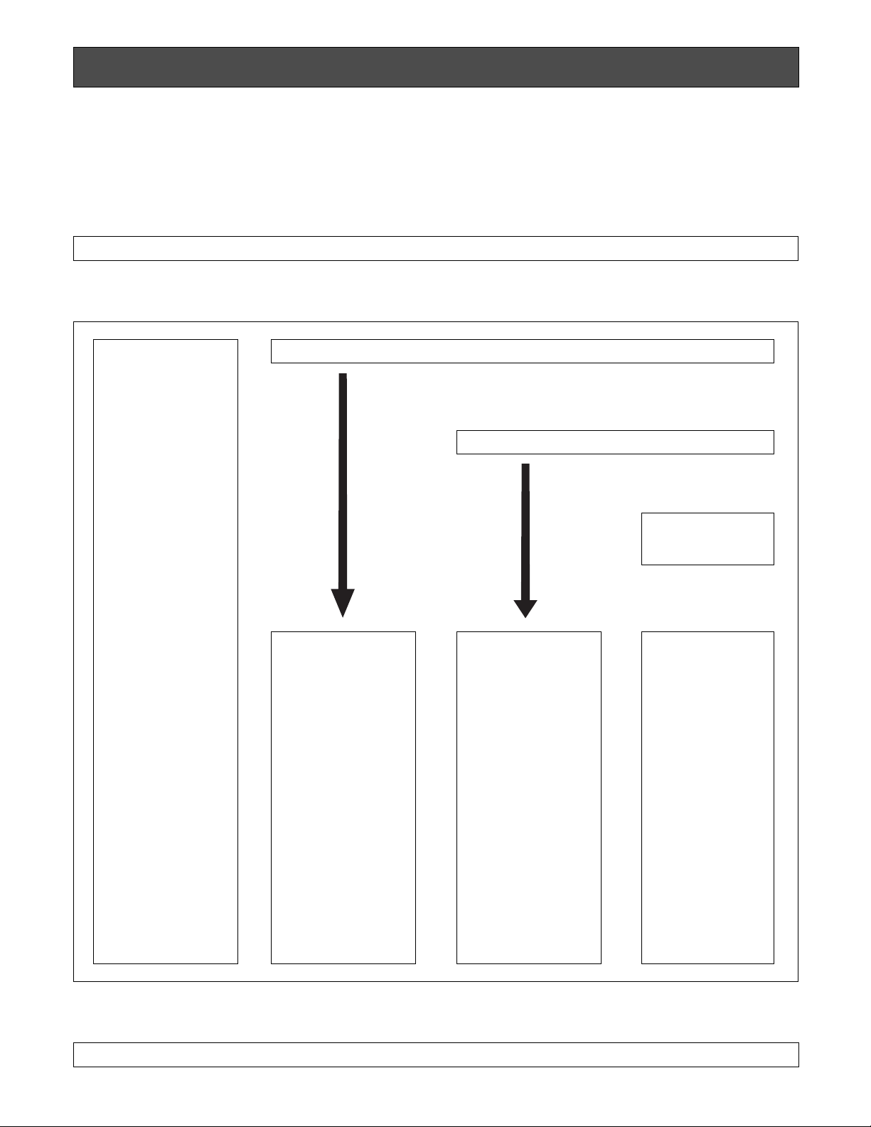
22
■ Basic Operating Flow
The operation starts with a log-in procedure. It proceeds to system unit selection, monitor selection and camera selection.
Alarm operations for the system such as alarm reset, suspension may be implemented. The operation ends with a log-out procedure.
OPERATING PROCEDURES (PS
•
Data)
LOG IN
SYSTEM UNIT SELECTION
MONITOR SELECTION
LOG OUT
SYSTEM
OPERATION
• Alarm Reset
• Alarm Suspend
• Alarm Suspend
Cancel
SYSTEM UNIT
OPERATION
• System Unit Setup
• System Function
• Alarm Recall
CAMERA
OPERATION
• Camera Setup
• Pan/Tilt (Slow)
• Iris/Focus/Zoom
• Preset Position
• Home Position
• Switching of
Colour/Black &
White
• Auto Panning
• Camera Patrol
• Camera Patrol
Stop
• Camera Patrol
Learn
• Camera Function
• Wiper/Defroster
• Auxiliary Control
1/2
CAMERA
SELECTION
d
d
d
MONITOR
OPERATION
• Switching of VTR
and CAM
• Multiscreen
Selection
• Still
• Electronic Zoom
• Sequence
• Sequence Pause
d
d
Page 22
23
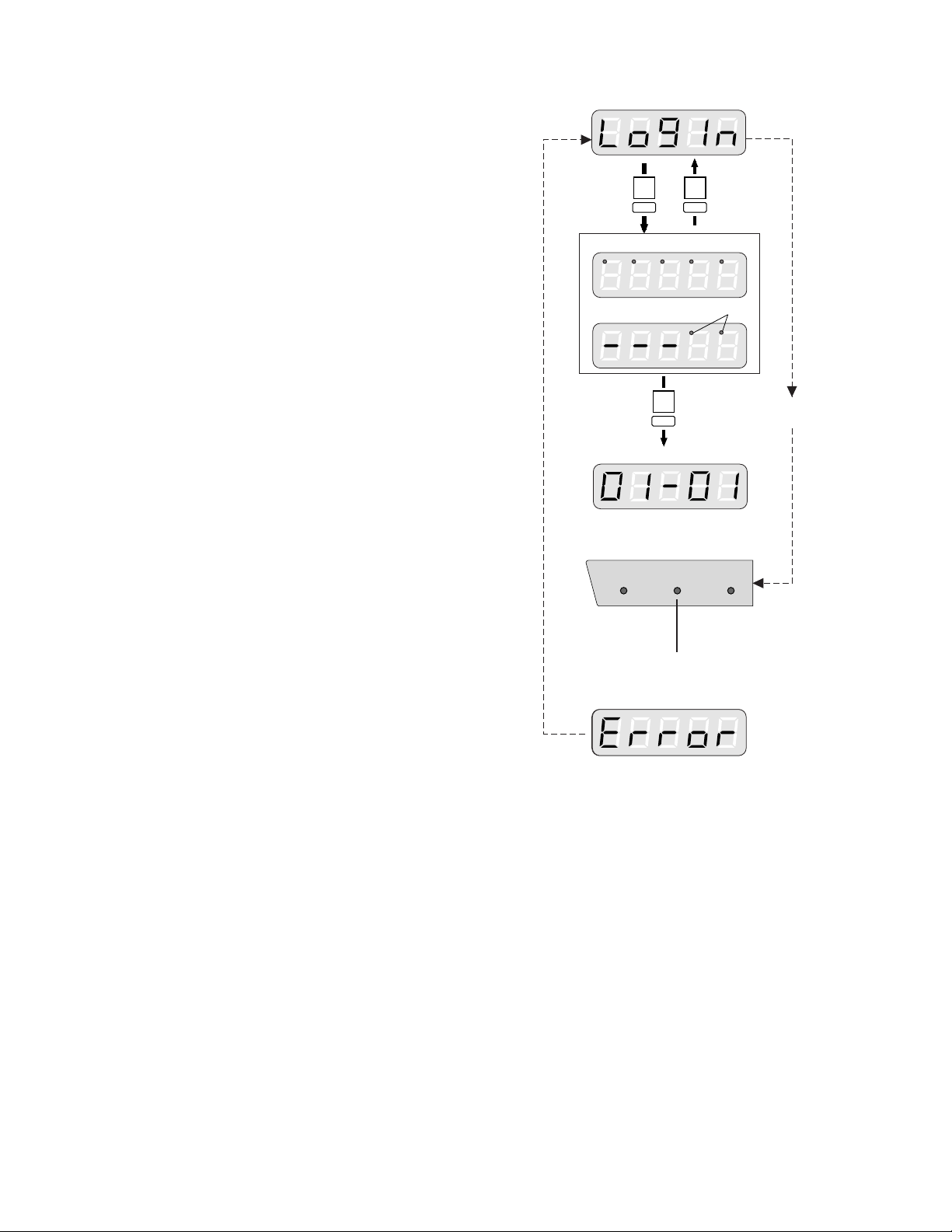
■ Log-in/Log-out
● Log-in
Right after powering up, the controller will be operable without password entry, provided user password certification is
set to Off in the setup menu.
When set to On, you will be prompted to enter your registered password. The default password is “12345”, but you
need to remember the password assigned to you by your
system administrator.
1. Insert the DC plug into the DC 9 V IN jack and connect
the AC adapter to an AC outlet.
2. The controller number, software versions and [LogIn]
appear in that order on the LED display.
The LOGIN indicator lights up. The controller is now
operable unless password certification is activated. If it
is not activated, proceed as follows.
3. Press the CAM/SET button.
4. Enter a 5-digit user password with the numeric buttons.
The initial factory setting is [12345].
5. Press the CAM/SET button.
6. If password entry for user authorization has been successful, the LOGIN indicator lights up.
The unit assigned to the UNIT A/UNIT button as number
1 is selected automatically.
If password entry has failed, [Error] appears on the display. The display returns to [LogIn].
● Log-out
1. Press the MON/ESC and CAM/SET buttons for about 2
seconds simultaneously.
2. [LogIn] appears on the display and the LOGIN indicator
goes off.
3. Disconnect the DC plug from the controller, and remove
the AC adapter from the AC outlet.
Note: If the power is not turned off after logout, the
alarm indicator and alarm suspend indicator will
display the same status as in normal operation.
SET
SET
ESC
Unauthorized
OPERATE LOGIN ALARM
SET
Ready for user password entry
Authorized
User password entry
Blink
The unit that is assigned to the UNIT A/UNIT
button as number 1 is selected automatically.
Lights after authorization
Goes off after logout
Certification
off
Page 23
24
● Selecting with UNIT A/UNIT B Button
The unit numbers (01-99) of some frequently used units can
be assigned to numeric buttons 1-9 in the setup. Units can
be divided in two groups, one assigned to the UNIT A and
the other to the UNIT B button. A frequently used system
unit can be easily selected by pressing one numeric button
and then the UNIT A or UNIT B button.
1. Enter a single digit number (1-9).
Omit this step when you wish to select unit number “1”,
as this unit is selected by default.
2. Press the UNIT A or UNIT B button while the SHIFT
indicator is off.
The selected unit address appears in the unit section of
the LED display.
The selected camera number appears in the camera
section of the LED display.
■ System Unit Selection
Connected system units can be selected either by their unit
number (01-99) or by a single-digit number (1-9) assigned
to the UNIT A or UNIT B button.
● Selecting with Unit Number
1. Enter a unit number (01-99) with the numeric buttons.
2. Press the SHIFT button to turn the shift indicator on,
then press the UNIT A/UNIT button.
The selected unit number appears in the unit section of
the LED display.
The selected camera number appears in the camera
section of the LED display.
Notes:
• To confirm the selected unit number when the monitor number appears in the unit section of the LED
display, take procedure 2 or press MON/ESC button .
• If no unit is connected, [Err] appears a few seconds
after unit selection. In such a case, confirm the unit
address and repeat the above procedure.
• If the unit address of a system unit is unknown, consult your system administrator.
• When multiple system units such as Data Multiplex
Unit are connected to the System Controller and the
UNIT A or UNIT B button is pressed, the camera
number on the controller's LED display will not
agree with the camera picture on the monitor.
In this case, select the monitor and camera as
described on the next page.
MON
LOGOUT
ESC SET
CAM
UNIT A
then
SHIFT
UNIT
MON
LOGOUT
ESC SET
CAM
UNIT A
UNIT B
or
UNIT
Page 24

25
■ Monitor Selection
A monitor is selected when multiple monitors are connected
to a system unit (e.g., a Video Multiplexer) to control such
functions as multiscreen display and electronic zoom.
1. Select the system unit connected to the monitor you
wish to control.
2. Enter a monitor number using the numeric buttons.
3. Press the MON/ESC button.
The selected monitor number appears in the monitor
section of the LED display.
The selected camera number appears in the camera
section of the LED display.
The monitor is now ready for control from the system
controller.
Notes:
• To confirm the selected monitor number, simply
take procedure 3 when the unit address appears in
the monitor section of the LED display.
• Each time the MON/ESC button is pressed, the unit
number and monitor number are displayed alternately on the LED.
• The setting is invalid if the unit in which the monitor
number has been set is not programmed.
• In the above case, repeat the same procedure after
confirming the monitor number. If you do not know
the monitor number, consult the administrator.
•When [--] appears in the monitor section of the LED
display, the selected system unit is not compatible
with the monitor selection.
• For further information, refer to the Operating Instructions for the system unit concerned.
■ Camera Selection
One of the cameras connected to the system unit is selected.
1. Select a system unit connected to the camera whose
picture you wish to view.
2. Enter a camera number using the numeric buttons.
The entered camera number appears on the LED display.
3. Press the CAM/SET button.
Note: [--] appears in the camera section of the LED dis-
play when an alarm is activated, when the multiscreen is displayed, or when a sequence mode is
running.
The following functions are available after selecting a camera.
• Pan/tilt
• Focus
• Zoom
• Iris
• Defroster ON/OFF (camera housing)
• Wiper ON/OFF (camera housing)
• Preset Position (Combination Camera)
• Home position (Combination Camera)
• Switching between colour and B/W picture
(Combination Camera)
• Auto pan (Combination Camera)
• Patrol Learn function (Combination Camera)
• Camera functions (Combination Camera)
The selected camera number can be incremented or
decremented by one if the system unit is equipped with the
camera switching feature.
1. Press the SHIFT button to turn the shift indicator on.
2. Press the EL-ZOOM/+ button to increment or the
STILL/– button to decrement the camera number.
MON
LOGOUT
ESC SET
CAM
MON CAM
LOGOUT
ESC SET
MON
ESC
Page 25

26
2. You can set a specified camera’s lens zoom automatically by moving the zoom wheel controller on the joystick controller.
Move the wheel controller to right to zoom in the image.
Move the wheel controller to left to zoom out the image.
You can also set the zoom by pressing the ZOOM
TELE/WIDE button.
Press the ZOOM TELE button to optically bring the
object closer, or press the ZOOM WIDE button to optically widen the scene.
3. Press the IRIS CLOSE button to close the iris, or the
IRIS OPEN button to open the iris.
If the IRIS CLOSE and IRIS OPEN buttons are pressed
simultaneously, the iris is reset to the default.
● Home/Preset Position
The camera moves to the preset position or back to the
home position, and the picture of the camera in that position appears on the monitor.
1. Press the HOME/PRESET button to move the camera
back to the home position.
2. Select a preset position number using the numeric buttons, then press the HOME/PRESET button to move the
camera to the position.
■ Camera Control
Cameras and their peripherals are controlled from the WVCU360CJ as follows. Some of the descriptions may not be
applicable if they refer to devices not equipped in your system.
The operating procedures on the following pages assume
that you have selected a system unit and a monitor.
● Pan/Tilt Control
Proceed as follows to control a combination camera or an
ordinary camera mounted on a pan/tilt head.
1. Move the pan/tilt head in the desired direction with the
joystick controller.
2. To slowly move the pan/tilt head, move the joystick
while holding down the SLOW button.
● Lens Control
This allows you to control a motorized lens.
1. If you are using a camera with an auto focus feature,
you can set the camera’s lens focus automatically by
pressing the top button on the joystick controller.
You can also adjust the lens focus automatically by
pressing the FOCUS NEAR and FOCUS FAR buttons
simultaneously.
If you are using a camera without an auto focus feature,
adjust the focus manually by pressing the FOCUS
NEAR or FOCUS FAR button while watching the monitor.
TELEWIDE
WIDE TELE
ZOOM
Joystick
SEQ PAUSE
SLOW
FOCUS
NEAR FAR
IRIS
CLOSE OPEN
IRIS RESET
HOME/PRESET
PROGRAM
PRESET
HOME/PRESET
MON
LOGOUT
ESC SET
CAM
PROGRAM
PRESET
Top button
AUTO FOCUS
Page 26

27
● Combination Camera Shortcuts
The shortcuts listed below are available for controlling combination cameras. For more details, refer to the Operating
Instructions included with the camera.
Selecting a PRESET position From #1 to #64
#1 [1] + [CAM FUNC]
#10 [1] + [0] + [CAM FUNC]
#64 [6] + [4] + [CAM FUNC]
AUTO PAN
ON [6] + [5] + [CAM FUNC]
OFF [6] + [6] + [CAM FUNC]
Speed Up [6] + [7] + [CAM FUNC]
Speed Down [6] + [8] + [CAM FUNC]
Setting Start Point [6] + [9] + [CAM FUNC]
Setting End Point [7] + [0] + [CAM FUNC]
Setting PAN Reverse [7] + [4] + [CAM FUNC]
AUTO MODE
MODE Off [7] + [1] + [CAM FUNC]
SEQ On [7] + [2] + [CAM FUNC]
SORT On [7] + [3] + [CAM FUNC]
ENDLESS PAN
On [7] + [6] + [CAM FUNC]
Off [7] + [7] + [CAM FUNC]
DIGITAL FLIP
On [7] + [8] + [CAM FUNC]
Off [7] + [9] + [CAM FUNC]
PROP. PAN/TILT
On [8] + [0] + [CAM FUNC]
Off [8] + [1] + [CAM FUNC]
SUPER-D2
On [8] + [4] + [CAM FUNC]
Off [8] + [5] + [CAM FUNC]
AUTO FOCUS
STOP AF On* [8] + [6] + [CAM FUNC]
STOP AF Off* [8] + [7] + [CAM FUNC]
AF On (Activate) [8] + [8] + [CAM FUNC]
HOME POSITION
Move to HOME [8] + [9] + [CAM FUNC]
B/W or C/L
B/W On* [9] + [0] + [CAM FUNC]
B/W Off* [9] + [1] + [CAM FUNC]
B/W AUTO* [9] + [2] + [CAM FUNC]
CAMERA ID
On [9] + [3] + [CAM FUNC]
Off [9] + [4] + [CAM FUNC]
AREA TITLE
NESW On [9] + [5] + [CAM FUNC]
USER On [9] + [6] + [CAM FUNC]
TITLE Off [9] + [7] + [CAM FUNC]
EL-ZOOM
On [9] + [8] + [CAM FUNC]
Off [9] + [9] + [CAM FUNC]
RESTART
Begin [1] + [0] + [0] + [CAM FUNC]
Memorize PRESET From #1 to #64**
Position #1 [1] + [0] + [1] + [CAM FUNC]
Position #10 [1] + [1] + [0] + [CAM FUNC]
Position #64 [1] + [6] + [4] + [CAM FUNC]
PATROL
PLAY [1] + [6] + [5] + [CAM FUNC]
STOP [1] + [6] + [6] + [CAM FUNC]
LEARN(Start) [1] + [6] + [7] + [CAM FUNC]
IRIS
Open [1] + [6] + [9] + [CAM FUNC]
Close [1] + [7] + [0] + [CAM FUNC]
EL-SHUTTER
On [1] + [7] + [1] + [CAM FUNC]
Off [1] + [7] + [2] + [CAM FUNC]
Speed Up [1] + [7] + [3] + [CAM FUNC]
Speed Down [1] + [7] + [4] + [CAM FUNC]
AGC
On [1] + [7] + [5] + [CAM FUNC]
Off [1] + [7] + [6] + [CAM FUNC]
SENS UP
On [1] + [7] + [7] + [CAM FUNC]
Off [1] + [7] + [8] + [CAM FUNC]
Up [1] + [7] + [9] + [CAM FUNC]
Down [1] + [8] + [0] + [CAM FUNC]
SENS UP AUTO
On [1] + [8] + [1] + [CAM FUNC]
Off [1] + [8] + [2] + [CAM FUNC]
Up [1] + [8] + [3] + [CAM FUNC]
Down [1] + [8] + [4] + [CAM FUNC]
LL SYNC phase
INC [1] + [8] + [5] + [CAM FUNC]
DEC [1] + [8] + [6] + [CAM FUNC]
PAN
180° turn [1] + [8] + [7] + [CAM FUNC]
CLEANING
On [1] + [8] + [8] + [CAM FUNC]
Off [1] + [8] + [9] + [CAM FUNC]
BW SW AUTO
30 sec. [1] + [9] + [0] + [CAM FUNC]
60 sec. [1] + [9] + [1] + [CAM FUNC]
300 sec. [1] + [9] + [2] + [CAM FUNC]
600 sec. [1] + [9] + [3] + [CAM FUNC]
Function Key Function Key
Notes:
• Shortcut operations marked with * will change parameter settings only. Actual operation takes place
when the conditions for the changed settings are met.
• When entering shortcuts marked with **, “NO REGS. ; FLIP ON” may appear on the monitor. Re-enter
the shortcut.
• Shortcuts may be ignored while PAN/TILT, ZOOM or FOCUS is in operation.
• PATROL LEARN saves only [1] through [6]+[4], [1]+[6]+[9] and [1]+[7]+[0] in the memory.
• PATROL PLAY stops when a shortcut other than [1]+[6]+[9] or [1]+[7]+[0] is entered.
Page 27

28
● Housing/AUX Control
When your system includes a camera housing, the
defroster and wiper equipped in it are controlled. When a
Receiver is installed in the system, an auxiliary device connected to it such as a buzzer or lamp will be also controlled.
8 Defroster
Press the DEF/AUX 2 button to enable or disable defroster
operation for the selected camera. The DEF/AUX 2 indicator next to the button is lit while it is in operation.
8 Wiper
Press the WIPER/AUX 1 button to enable or disable wiper
operation for the selected camera. The WIPER/AUX 1 indicator next to the button is lit while it is in operation.
Note: To prevent early wiper wear, be sure to turn off the
wiper whenever it is not needed, or before selecting
another camera for viewing.
8 Auxiliary 1/2
1. Press the SHIFT button to turn the SHIFT indicator on.
2. Press the WIPER/AUX 1 or DEF/AUX 2 button to
enable or disable the auxiliary function for the selected
camera. The respective indicator next to the button is lit
while it is in operation.
Note: Auxiliary control may be ignored while zooming,
focusing or panning/tilting is in operation.
■ Data Multiplex Unit Control
When more than one Data Multiplex Unit are connected
with the controller as shown in System Connection Example
2 on page 14, you can select a camera directly with the
camera number, without typing a system unit address.
● Setting
Camera numbers are specified by the UNIT switch or in the
setup menu for the WJ-MP204C.
For further details, refer to the manual included with the
Data Multiplex Unit.
When more than one controller is connected in the system,
remember settings are needed for the MODE DIP switch
and CONTROLLER NO. switch of the controllers as
described on page 16.
● Camera Selection
1. Press a camera number using the numeric buttons.
2. Press the CAM/SET button.
Unit Address Camera Number
of WJ-MP204C
11, 2, 3, 4
25, 6, 7, 8
3 9, 10, 11, 12
4 13, 14, 15, 16
DEF
AUX 2
WIPER
AUX 1
DEF
SHIFT
AUX 2
WIPER
AUX 1
MON
LOGOUT
ESC SET
CAM
SET
CAM
Page 28

29
■ Video Multiplexer Control
Some of the major functions equipped in a Video
Multiplexer are remotely controlled from the System
Controller. For more information, refer to the manual included with the Video Multiplexer.
The operating procedures on the following pages assume
that you have selected a system unit and a monitor.
● Multiscreen Selection
1. Press the MULTISCREEN SELECT button. The select-
ed multiscreen monitor displays a split screen.
2. Press the button repeatedly to select the number of
segments you wish the multiscreen to display. Each
time the button is pressed, the number changes as follows depending on the number of inputs (16 or 9).
16-input: 4 → 9 → 16 → 4 screen segments
9-input: 4 → 9 → 4 screen segments
● Still Picture
There are two ways of displaying still pictures on the multiscreen monitor.
8 Specific camera still
1. Select a camera number using the numeric buttons,
then press the STILL/– button. The selected camera
picture freezes on the multiscreen while the STILL/–
indicator is lit.
2. Press the STILL/– button to cancel still display mode.
8 All cameras still
1. Enter 0 with the numeric buttons, then press the
STILL/– button. All camera pictures freeze on the multiscreen while the STILL/– indicator is lit.
2. Press the STILL/– button to cancel the still display
mode.
● Electronic Zoom
A picture displayed on the monitor can be electronically
zoomed in, and the enlarged area in the picture can be
moved using the joystick.
1. Press the EL-ZOOM/+ button. The EL-ZOOM/+ indica-
tor is lit, and a plus mark [+] appears in the center of
the monitor screen.
2. Move the [+] mark into the zoom area moving the joystick.
3. Press the EL-ZOOM/+ button again to zoom.
You can move the enlarged area on the monitor using
the joystick.
4. Press the EL-ZOOM/+ button to cancel the zoom mode.
The EL-ZOOM/+ indicator goes off.
STILL
0
–
Example of Quad Picture
MULTI SCREEN SELECT
1
3 4
2
EL-ZOOM
+
STILL
–
Page 29

30
● Viewing Playback
VTR playback pictures are displayed on the selected spot
or multiscreen monitor.
1. With the connected VTR in playback mode, press the
VCR/CAM button to turn on the VCR indicator.
Playback pictures are displayed on the selected monitor.
2. Press the VCR/CAM button again to cancel viewing
playback. The VCR indicator goes off.
Note: This function is automatic when PLAYBACK
AUTO is set to ON in the Video Multiplexer setup
and the playback signal is supplied to the Video
Multiplexer. Set PLAYBACK AUTO to OFF in the
setup when you wish manual operations as
described above.
● Sequence Control
A preset sequence is displayed on the selected spot or
multiscreen monitor. The paused picture can be moved by
one step to the previous or next frame.
1. Press the SEQUENCE button. The sequence is displayed on the monitor while the SEQUENCE indicator is
lit.
2. To pause the sequence, press the SEQ PAUSE button.
3. To move the sequence one step forward, press the EL-
ZOOM/+ button.
4. To move the sequence one step back, press the
STILL/– button.
5. To cancel the sequence pause, press the SEQ PAUSE
button again.
VCR CAM
STILL
–
SEQ PAUSE
SEQUENCE
PATROL
STOP
SLOW
SEQ PAUSE
SLOW
EL-ZOOM
+
Page 30

31
■ Digital Disk Recorder Control
A Digital Disk Recorder is controlled from the System Controller using shortcuts assigned to numeric buttons.
For more information, refer to the manual included with the Digital Disk Recorder.
The operating procedures on the following pages assume that you have selected a system unit and a monitor.
● WJ-HD100 Shortcuts
The shortcuts listed below are available for controlling a digital disk recorder. For more details, refer to the Operating
Instructions included with the digital disk recorder.
Item
SHIFT
SETUP
FUNCTION
Step Playback REW.
Play/Stop Selected Alarm
Record
Show/Hide SETUP MENU
The top of the oldest record will be
accessed.
Jump to Oldest.
WV-CU360CJ
Setup Item Selection
Parameter Selection
Move Cursor Back A Step
Show/Hide Alarm History
Search Alarm History
WJ-HD100 Note
Button lock is released automatically by opening the setup menu.
Operate LCD Button.
STOP
SETUP/ESC
Hold down
2 seconds
STEP
/
PUSH– PAUSE
SET
/
/
PUSH– PAUSE
SET
/
/
STOP
SETUP/ESC
STOPPLAY
CAM
MON
ESCSET
REW/FF
/
SETUP
FUNCTION
Hold down
2 seconds
MON
ESC
ALM RESET
ALM RECALL
SHIFT
Recording
REC
SETUP
FUNCTION
SHIFT
Stop
Stop Playback
Stop Recording
STOP
SETUP/ESC
STOP
STOP
SETUP
FUNCTION
SHIFT
Playback
PLAY
SETUP
FUNCTION
SHIFT
Pause
PUSH– PAUSE
SET
/
/
SETUP
FUNCTION
SHIFT
Step Playback FWD.
PUSH– PAUSE
SET
/
/
STEP
/
PUSH– PAUSE
SET
/
/
STEP
/
SETUP
FUNCTION
SHIFT
SETUP
FUNCTION
SHIFT
Skip Playback FWD.
PUSH– PAUSE
SET
/
/
REW/FF
/
SHIFT
SETUP
FUNCTION
Skip Playback REW.
PUSH– PAUSE
SET
/
/
REW/FF
/
Jump to Latest.
The top of the latest record will be
accessed.
PUSH– PAUSE
SET
/
/
REW/FF
/
Press
JogDial
SETUP
FUNCTION
SHIFT
PUSH– PAUSE
SET
/
/
REW/FF
/
Press
JogDial
SETUP
FUNCTION
SHIFT
SETUP
FUNCTION
SHIFT
SHIFT
SETUP
FUNCTION
Exclusive use to stop playback.
Exclusive use to stop recording.
Hold down
2 seconds
Hold down
2 seconds
Press
JogDial
Press
JogDial
Page 31

32
SETUP
FUNCTION
SHIFT
● WJ-HD500A Shortcuts
The shortcuts listed below are available for controlling a digital disk recorder. For more details, refer to the Operating
Instructions included with the digital disk recorder.
DAYLIGHT SAVINGS
OFF, INT or EXT selectable
Operate LCD Button.
Item WV-CU360CJWJ-HD100 Note
DAYLIGHT
SAVINGS
SHIFT
SETUP
FUNCTION
31
Timer REC Mode
Selection
SHIFT
SETUP
FUNCTION
Button Lock OFF
Operate LCD Button.
Operate LCD Button.
Button Lock ON
SHIFT
SETUP
FUNCTION
31
SHIFT
SETUP
FUNCTION
30
Item Controller Operation Note
Step Playback FWD
Step Playback REW
Pause
Playback
Recording
Stop
Stop Playback
Stop Recording
Alarm Search OFF
Alarm Search ON
Button Lock OFF
Button Lock ON
Daylight Savings ON/OFF
Timer Mode Selection
Record List Display ON/OFF
Record Search Window ON
Equal to REC button
For both Manual Recording and Playback
Exclusive use to stop playback
Exclusive use to stop recording
Internal, External, Off
Index
Index/Shuttle
SETUP
FUNCTION
SHIFT
SETUP
FUNCTION
SHIFT
SETUP
FUNCTION
SHIFT
SETUP
FUNCTION
SHIFT
SHIFT
SETUP
FUNCTION
SHIFT
SETUP
FUNCTION
3 3
SETUP
FUNCTION
SHIFT
SETUP
FUNCTION
SHIFT
SHIFT
SETUP
FUNCTION
SHIFT
SETUP
FUNCTION
31
SHIFT
SETUP
FUNCTION
30
SHIFT
SETUP
FUNCTION
31
SHIFT
SETUP
FUNCTION
SHIFT
SETUP
FUNCTION
SHIFT
SETUP
FUNCTION
Page 32

33
Item Controller Operation Note
Screen Display ON/OFF
Group Selection
Show/Hide Alarm Log
Skip Playback FWD.
Skip Playback REW.
Record List 1 line Up
Record List 1 line Down
Record List Turn Next Page
Record List Turn Prev. Page
Playback of Selected Record
Backward Search in Window
Forward Search in Window
Increment Parameter in Window
Decrement Parameter in Window
Search Window Display ON/OFF
Alarm Log 1 line Up
Alarm Log 1 line Down
Playback of Selected Alarm
Record
Backward Search in Window
Forward Search in Window
Increment Parameter in Window
Decrement Parameter in Window
Search Window Display
Selection
Speed change 1/2, 1, 2, 5
Speed change 1/2, 1, 2, 5
Record List
Record List
Record List
Record List
Record List
Record List
Alarm Log
Alarm Log
Alarm Log
Alarm Log
Alarm Log
Time & Date, Alarm CH, OFF
SHIFT
SETUP
FUNCTION
SHIFT
SETUP
FUNCTION
SHIFT
ALM RESET
ALM RECALL
SHIFT
SETUP
FUNCTION
SHIFT
SETUP
FUNCTION
SHIFT
SETUP
FUNCTION
SHIFT
SETUP
FUNCTION
SHIFT
SETUP
FUNCTION
SHIFT
SETUP
FUNCTION
SHIFT
SETUP
FUNCTION
SHIFT
SETUP
FUNCTION
SHIFT
SETUP
FUNCTION
SHIFT
SETUP
FUNCTION
SHIFT
SETUP
FUNCTION
SHIFT
SETUP
FUNCTION
SHIFT
CAM
SET
SHIFT
EL-ZOOM
+
SHIFT
STILL
–
SHIFT
MON
ESC
Page 33

34
Item
■ Alarm Operation
When the WV-CU360CJ receives an alarm signal from a
system unit, the alarm indicator on the controller blinks.
The alarm indicator changes from blinking to steady light
when the alarm is automatically reset.
The camera number [---] appears in the camera section of
the LED display.
● Alarm Reset
1. Press the ALM RESET/ALM RECALL button.
The alarm indicator on the controller goes off.
Notes:
• Alarm reset operations including auto reset are
applied to all system units, not to a selected one.
• Alarm reset mode differs depending on the system
unit connected to the WV-CU360CJ.
• Confirm that the SHIFT button is released.
● Alarm Suspension
The alarm suspension mode is activated or deactivated.
Use this function when you do not want to be disturbed by
alarm input as for example during setup operations.
1. Press the ALM SUSPEND button. The ALM SUSPEND
indicator lights up.
Alarm input is ignored while the indicator is lit.
2. To cancel alarm suspension, press the ALM SUSPEND
button again.
Note: The alarm suspension is applied to all system
units, not to a selected one.
● Alarm Recall
The alarm event log is recalled and displayed on the monitor.
1. Select the desired system unit and monitor.
2. Press the ALM RESET/ALM RECALL button while the
SHIFT indicator is lit. The ALM RECALL indicator lights
up. The alarm log appears on the monitor.
3. To cancel the alarm recall function, press the ALM
RESET/ALM RECALL button while the SHIFT indicator
is lit.
Controller Operation Note
Copy to DVD
Copy Cancel
DVD Copy Record Display Equal to EL-ZOOM
SHIFT
SETUP
FUNCTION
SHIFT
SETUP
FUNCTION
SHIFT
SETUP
FUNCTION
ALM RESET
ALM RECALL
ALM
SUSPEND
ALM RESET
SHIFT
ALM RECALL
ALM
SUSPEND
Page 34

35
REMOTE SETUP of UNITS & CAMERAS
You can set up the system unit and the camera with the
setup menu by this controller.
You can use the controller to set up system units and cameras.
This section describes the main remote setup procedures.
Some of the descriptions may not be applicable if they refer
to devices not equipped in your system.
For further information on the default settings and operating
procedures, refer to the Operating Instructions included
with the individual units.
■ System Unit Setup
1. Select the desired system unit compatible with PS•Data
mode.
2. Press the SETUP/FUNCTION button for more than 2
seconds. The SETUP indicator lights up.
The Setup menu for the system unit appears on the
monitor.
3. To complete the setup, press the SETUP/FUNCTION
button for 2 seconds or more.
The SETUP indicator goes off.
Note: If you change the default baud rate or parity check,
the system unit setup function is disabled.
Keys used for system unit setup
■ Camera Setup
1. Select the desired camera.
2. Press the CAM SETUP/CAM FUNCTION button for 2
seconds or more to access the Camera Setup menu.
The CAM SETUP indicator lights up.
3. Move the cursor with the numeric buttons 2 (Up) or 8
(Down), then select a parameter with the buttons 6
(Right) or 4 (Left).
4. Press the CAM/SET button to execute the parameter or
enter a submenu.
5. To return to the previous menu, press the MON/ESC
button.
6. Press the CAM SETUP/CAM FUNCTION button for 2
seconds or more to complete the camera setup.
To move the cursor.
To select a parameter.
To execute the parameter or
enter a submenu
To return to the previous menu
CAM
SET
MON
ESC
EL-ZOOM
STILL
–
+
FUNCTION
SETUP
CAM FUNCTION
CAM SETUP
Example of Setup Menu for WJ-MP204C
WJ-MP204C SETUP MENU x.xx
COMMUNICATION
SYSTEM
(Example of Camera Setup menu)
*** SET UP MENU ***
PRESET 1*
MAP
HOME POSITION
SELF RETURN
AUTO MODE
AUTO PAN KEY
DIGITAL FLIP
LOCAL/REMOTE
SPECIAL1
CAMERA
RS485 SET UP
15
10MIN
AUTO PAN
SEQ
OFF
LOCAL
MON
LOGOUT
ESC SET
CAM
MON
LOGOUT
ESC SET
CAM
Page 35

36
■ Camera Patrol Learning
There are two ways of setting up camera patrol learning.
One is to use the camera setup menu and the other is to
operate the camera.
Follow the procedures below to set up while operating the
combination camera.
1. Select the desired system unit, monitor and combination camera.
2. Press the PATROL PLAY/PATROL LEARN button
while holding down the PROGRAM/CAM SETUP/CAM
FUNCTION button.
[LEARNING] appears on the monitor.
3. Operate the camera using the following controls so that
it traces a routine course most frequently patrolled. The
learning is programmed for 30 seconds for later patrol
play.
• Pan/Tilt (Joystick)
• Iris (Open/Close)
• Focus (Far/Near)
• Zoom (Tele/Wide)
• Preset Position
Note: The memorized parameters may differ somewhat
depending on the camera type. Refer to the manual
included with the camera.
4. To stop the learning, press the SEQUENCE/PATROL
STOP button while holding down the PROGRAM/CAM
SETUP/CAM FUNCTION button.
[LEARNING] disappears from the monitor.
7. Move the cursor to [SPECIAL] on the Setup menu, and
press numeric buttons 4 and 6 simultaneously for 2
seconds or more to display the special menu.
8. Move the cursor to [CAMERA RESET]* on the Setup
menu, and press buttons 4, 5 and 6 simultaneously to
reset all the functions to the defaults.
* The menu to reset the camera functions differs depend-
ing on the camera:
[SPECIAL] for the WV-CS650, [SPECIAL 2] for the WVCS854, and [END] for fixed cameras etc.
Notes:
• If camera setup is started using the buttons on the
camera, all future operations for setup must be performed using the buttons on the camera.
If camera setup is started using the System
Controller, all future operations for setup must be
performed using the same controller.
• For further information, refer to the Operating
Instructions for the selected camera.
Keys used for camera setup
To move the cursor
To select a parameter
To execute the mode or
enter a submenu
To return to the previous menu
CAM
SET
MON
ESC
8
2
4
6
PROGRAM
CAM SETUP
CAM FUNCTION
PATROL PLAY
PATROL
LEARN
LEARNING
PROGRAM
CAM SETUP
CAM FUNCTION
SEQUENCE
PATROL
STOP
Page 36

37
■ Camera Preset Position
There are two ways of presetting camera positions.
One is to use the camera setup menu of the combination
camera and the other is to operate the System Controller as
follows.
1. Select the desired system unit, monitor and camera.
2. Move the camera to a position you wish to preset, using
the joystick.
Adjust the picture using the following buttons.
• Iris (Open/Close)
• Focus (Far/Near)
• Zoom (Tele/Wide)
Note: The memorized parameters may differ somewhat
depending on the camera type. Refer to the manual
included with the camera.
3. Type a number with the numeric buttons for the preset
position. The typed number appears in the CAMERA
section of the LED display.
4. Press the HOME/PRESET/PROGRAM PRESET button
while holding down the PROGRAM/CAM SETUP/CAM
FUNCTION button.
The position and its number are memorized for later
recall.
PROGRAM
CAM SETUP
CAM FUNCTION
HOME/PRESET
PROGRAM
PRESET
MON
LOGOUT
ESC SET
CAM
Page 37

39
For WJ-FS616C Multiplexer System
Page 38

40
MAJOR OPERATING CONTROLS & THEIR FUNCTIONS
■ Front View (Template for WJ-FS616C)
System Controller
OPERATE LOCK ALARM
SPOT
AUTO/+
IRIS
CLOSE OPEN
NEAR FAR
TELE WIDE
FOCUS
ZOOM
IRIS RESET
VTR
CAM
MULTI
SCREEN
SEQUENCE
EL-ZOOM
MULTI SELECT
STILL
PRE-POSI
ALT
ALM RESET
ALM SUSPEND
FUNCTION
ALL RESET
CAMERA SET
ON OFF ON/OFF
SETUP
AUTO
FOCUS
HOME/-
UNIT
CAM
ESC SET
R
DOWN
UNIT CAMERA
For Multiplexer
WV-CU CJ
360
T/L MODE
CAMERA SITE CONTROL
AUX 2
AUX 1
!7!8!9
@0@1@2
@3@4@5
@6@7@8
@9#0
q w e r t y
u
io!0!1!2!3!4!5!6
q Operate Indicator (OPERATE)
Is lit while power is supplied to the System Controller.
w Lock Indicator (LOCK)
Is lit while operation of the System Controller and WJFS616C is prohibited by the connected computer. The
lock can be released by sending a command from the
computer.
e Alarm Indicator (ALARM)
Blinks when an alarm is activated. Blinking changes to
steady light when the alarm is automatically reset.
To turn the indicator off, press the ALM RESET button.
r LED Display (UNIT CAMERA)
LED display allowing you to confirm the number of the
system unit and camera in operation. The CAMERA
section will display “–” when operating in multiscreen or
sequence mode.
t Iris buttons (IRIS, CLOSE/OPEN)
Close or open the lens iris of cameras equipped with
the specified lens.
When these buttons are pressed at the same time, the
lens iris is reset to the factory setting.
y Zoom wheel controller
This control is used for zooming cameras equipped
with the specific lens. Moving the control to the right will
zoom in the image. Moving the control to the left will
zoom out the image.
u Joystick Controller
Used to operate the pan/tilt head manually, or to move
the cursor to the desired position in the setup menu of
the Video Multiplexer.
}: Upward
{: Downward
]: Left
[: Right
i Top button
Pressing this button will automatically set the lens focus
of a specified camera.
o Focus buttons (FOCUS, NEAR/FAR)
Adjust the lens focus of cameras equipped with the
specified lens.
Page 39

41
!0 Zoom buttons (ZOOM, TELE/WIDE)
Zoom cameras equipped with the specified lens.
!1 Auto/Increment button (AUTO/+)
Activates the auto panning function.
During the setup, this button is used to select the
desired parameter in the setup menu.
!2 Home/Decrement button (HOME/–)
Moves the camera to the home position.
During the setup, this button is used to select the
desired parameter in the setup menu.
!3 Auto Focus button (AUTO FOCUS)
Activates the auto focus function when the specified
camera with auto focus feature is selected.
!4 Camera/Set button (CAM/SET)
CAM: Selects a camera. Enter a camera number with
the numeric buttons, then press the CAM/SET button.
SET: Executes the currently highlighted setting in the
setup menu.
!5 Numeric Buttons (0 - 9)
These buttons are used for numeric input into the system, such as the number of a camera you want to
select.
!6 Unit/Escape button (UNIT/ESC)
UNIT: Selects a WJ-FS616C unit. Enter a unit number
with numeric buttons, then press the UNIT/ESC button.
ESC: Escapes from the currently highlighted selection
and return to the previous menu window in the
setup.
!7 Alternate button (ALT)
In combination with certain other buttons, activates special functions.
For example, in combination with the ALM SUSPEND,
EL-ZOOM or MULTI SELECT button, it is used to control
the VTR (VCR).
!8 Multiscreen Monitor button (MULTI SCREEN)
Selects the multiscreen monitor connected to the MULTISCREEN OUT connector of the Video Multiplexer.
The indicator lights up when the multiscreen monitor is
selected.
Note: When REC OUT of the Video Multiplexer is used
as connector for the Multiscreen 2 Monitor, this button alternately selects the Multiscreen or
Multiscreen 2 Monitor.
The indicator blinks when the Multiscreen 2 monitor
is selected.
!9 Spot Monitor button (SPOT)
Selects the spot monitor connected to the SPOT OUT
connector of the Video Multiplexer.
The indicator lights up when the spot monitor is selected.
@0 Alarm Reset button (ALM RESET)
Cancels an active alarm.
Pressing this button while the alarm function is activated will reset an alarm of the currently selected unit and
return the system to the condition before the alarm
function was activated.
Pressing it in combination with the ALT button will reset
all alarms.
@1 Sequence button (SEQUENCE)
Activates the sequence mode. In this mode, a series of
camera pictures is displayed in succession on the monitor screen for the specified duration.
The indicator lights up when this mode is selected.
@2 VTR (VCR)/Camera selection button (VTR/CAM)
Selects the camera picture or VTR (VCR) playback picture for display on the multiscreen monitor.
The indicator lights up when the VTR (VCR) mode is
selected.
Note: The above operation is not valid unless multi-
screen monitor is selected using the MULTISCREEN button.
@3 Alarm Suspend button (ALM SUSPEND)
Pressing this button for more than two (2) seconds suspends activation of the alarm without changing the current alarm mode setup.
The indicator lights up when the alarm suspension
mode is selected.
@4 Electronic Zoom button (EL - ZOOM)
Zooms the picture presently displayed on the multiscreen monitor.
@5 Multiscreen Selection button (MULTI SELECT)
Selects the multiscreen pattern to be displayed on the
multiscreen monitor while monitoring the camera picture or VTR (VCR) playback picture.
Pressing this button repeatedly will switch the screen as
follows:
Camera Picture:
4 → 7 → 9 → 10 → 13 → 16→ 4 screen segments
VTR (VCR) Playback Picture:
4 → 9 → 16→ 4 screen segments
@6 Function button (FUNCTION)
Displays the VTR (VCR) playback picture with the camera pictures on the multiscreen monitor.
The indicator lights up when the combined mode is
selected, and turns off when the playback picture is
selected.
During the setup, this button is used to select the next
page.
@7 Preset Position button (PRE - POSI)
In combination with the numeric buttons and CAM
(SET) button, moves the camera to the desired preset
position.
Page 40

42
@8 Still button (STILL)
Freezes the picture on the multiscreen monitor.
The indicator lights up when the still mode is selected.
@9 Camera Set buttons (CAMERA SET ON/OFF)
Open or close the camera setup menu on the monitor
screen.
ON: Opens the selected camera setup menu on the
monitor, if applicable.
The indicator lights up when the camera setup
menu is displayed.
OFF: Closes the camera setup menu.
#0 Set Up button (SET UP ON/OFF)
Opens or closes the WJ-FS616/FS616C setup menu on
the monitor.
Page 41

43
INSTALLA TIONS (For WJ-FS616/FS616C)
The installation should be made by qualified service personnel or system installers according to the following instructions.
CAUTION
■ System Connections
● Connection Example
The connection example shows cameras and an alarm sensor connected to the Video Multiplexer. A time lapse VTR will
record pictures for later playback. The spot monitor and multiscreen monitor will display live and playback pictures while these
devices are being operated from System Controller WV-CU360CJ.
4
8
12
16
3
7
11
15
2
6
10
14
1
5
9
13
PUSH OPEN
16
POWER
LOCK
ON
OFF
ALARM
MULTI
SCREEN
MULTISCREEN
SELECT
RESET SPOT SEQUENCE
VCR
CAM
CAMERA/PRESET POSITION
Video
Data RS-485
Video Multiplexer
WJ-FS616C
Time Lapse VCR
Personal Computer
(Software)
System Controller
WV-CU360CJ
Spot Monitor
Live 1-16ch
Multiscreen Monitor
Live 1-16ch
Playback 1-16ch
RS-232C/Wired
Alarm Sensor
AUX
Alarm
System Controller
OPERATE LOCK ALARM
SPOT
AUTO/+
IRIS
CLOSE OPEN
NEAR FAR
TELE WIDE
FOCUS
ZOOM
IRIS RESET
VTR
CAM
MULTI
SCREEN
SEQUENCE
EL-ZOOM
MULTI SELECT
STILL
PRE-POSI
ALT
ALM RESET
ALM SUSPEND
FUNCTION
ALL RESET
CAMERA SET
ON OFF ON/OFF
SETUP
AUTO
FOCUS
HOME/-
UNIT
CAM
ESC SET
UNIT CAMERA
For Multiplexer
WV-CU CJ
360
T/L MODE
CAMERA SITE CONTROL
AUX 2
AUX 1
Page 42

44
● DA TA Port Connection (For Multiplexer)
Data ports are connected with RS-485 cables among devices using the Camera Communication protocol as follows.
Note: When using cables other than those supplied, make sure to use shielded 4-wire twisted pair cable suitable for RS-485
communication.
• Internal Diagram
• Basic Connection
■ DIP Switch Setting (For Multiplexer)
An 8-bit DIP switch mounted on the rear panel specifies the communication mode, etc. The default position is marked with an
asterisk *.
SW position
OFF
Not used
On*
On
Not used
Not used
Function
ON
Bit 1
Bit 2
Bit 3
Bit 4
Bit 5
Bit 6
Bit 7
Bit 8
Operation mode
Operation mode
Operation mode
Reserved
Line termination
Administrator mode
Reserved
Data transmission
See Unit Version*
See Unit Version*
See Unit Version*
Fixed to OFF*
Off
Off*
Fixed to OFF*
Fixed to OFF*
No. No.
1 1
1
6
WJ-FS616C ← WV-CU360CJ
2 2
WJ-FS616C ← WV-CU360CJ
3 3
WJ-FS616C → WV-CU360CJ
4 4
WJ-FS616C → WV-CU360CJ
5 5
6 6
Data Flow
–
–
Name
GND
TX(B)
TX(A)
RX(B)
RX(A)
GND
Video Multiplexer
WJ-FS616C
DATA
INOUT
Termination:
ON
Controller end
TERM.
OFF
ON
RS-485 Cable
1
6
System Controller
WV-CU360CJ
DATA
Termination:
ON
TX (B)
TX (A)
RX (B)
RX (A)
0
1
9
2
8
3
7
4
6
5
DATAMODECONTROLLER No.
DC 9V IN
Page 43

45
■ Controller Number Setting
Set this switch always to 1 when using the System
Controller in a system including a Multiplexer WJFS616/FS616C.
● Switch Setting Procedures
1. Remove the DC plug from the rear of the controller.
2. Set the MODE switch referring to the table.
• The bit switches #1 to #3 should be set to positions that
match the version of the Multiplexer installed in the system.
• Bit 5 opens or terminates the communication chain. The
switch should be set to OFF when the controller is located in an intermediate position of the chain.
• Bit 6 specifies either Operator or Administrator as the
Administrator mode. Set to on when setting up the controller.
• Bits 4, 7 and 8 are reserved.
3. Set the CONTROLLER NO. switch to 1.
4. Connect the DC plug to the controller.
● Unit Version
The unit ID is defined by the upper 3 bits depending on the
software version installed in the unit.
• WJ-FS616
• WJ-FS616C
OFF
ON
12345678
MODE
0
1
9
2
8
3
7
4
6
5
CONTROLLER No.
12345678
MODE
OFF
ON
Page 44

46
SETUP PROCEDURES (For WJ-FS616/FS616C)
To display the setup menus for the WV-CU360CJ System Controller on the LED display, set the MODE switch and power up
the controller as described below.
■ Prior to Setup
Do the following before entering the setup mode.
1. Confirm that all necessary connections and switch settings are complete.
2. With the power turned off, move bit #6 of the MODE
switch on the rear to ON (administrator) position.
3. Supply power to the controller.
4. Turn on the power of cameras and other system units.
5. The LCD displays [SEtUP]. The controller is ready to
enter the setup mode.
When setup is completed, restore the switch to its original
position.
1. With the power turned off, move bit #6 of the MODE
switch on the rear to OFF (operator) position.
2. Supply power to the controller.
■ Buttons and Controls Used for Setup
The following buttons and joystick operations are used for
setup.
0
9
Numeric buttons: To select a parameter
CAM/SET button: To execute modes and
parameters
To enter a submenu
UNIT/ESC button: To return to the previous
menu
CAM
SET
UNIT
ESC
Up: To select a setup menu
Down: To select a setup menu
Left: To decrease the parameter
Right: To increase the parameter
HOME/-
AUX 1
AUTO/+
AUX 2
or
or
Page 45

47
■ Controller Setup
Set up the baud rate and parity check mode for the controller while observing the LED on the front panel.
● Administrator Authorization
1. Press the CAM/SET button while [SEtUP] is displayed.
The [- - - - -] prompt appears.
2. Enter a password with the numeric buttons, then press
the CAM/SET button.
The default setting is [12345].
3. If the password entered is valid, [SPEED] appears. If
password entry failed, the menu returns to [SEtUP].
● Baud Rate
In this menu, the communication speed (bps: bits per second) is selected. The communication speed should match
that of the WJ-FS616/FS616C.
1. Display [SPEED] and press the CAM/SET button twice.
2. Select a parameter entering a bracket-enclosed number, e.g., (3), moving the joystick to right and left, or
pressing the [+] and [–] buttons.
The default setting is 9 600 bps.
(1) 2 400: 2 400 bps
(2) 4 800: 4 800 bps
(3) 9 600: 9 600 bps
(4) 19 200: 19 200 bps
Note: Selecting a slower rate (e.g., 2 400 bps) will delay
the response time (e.g., the time until an activated
alarm is reset).
3. Press the CAM/SET button to validate the selection.
4. Press the ESC button to go back to the previous menu.
Menu
Selection
Move Joystick
up and down
to select
Setup Menus
Parameter Selection (default*)
LED Display
blinking
Setup
Administrator
Password
Prompt
Speed
Parity
Initial
Display
Authorization
Baud Rate
(bps)
Press
twice
Parity Check
CAM
SET
CAM
SET
MON
ESC
LED prompts you to enter password
Enter a 5-digit password,
press (12345*)
(1) 2 400 (2) 4 800 (3) 9 600*
(4) 19 200
(1) None (2) Even*
Reading Function
OK
No
CAM
SET
Page 46

48
● Parity
In this menu the parity check mode is selected.
1. Display [PrtY] and press the CAM/SET button twice.
2. Select a parameter with the joystick.
The default setting is Even.
n: None
E: Even parity
3. Press the CAM/SET button to validate the selection.
4. Press the ESC button to go back to the previous menu.
Page 47

49
OPERATING PROCEDURES (For WJ-FS616/FS616C)
■ Camera Selection
One of the cameras connected to the system unit is selected.
1. Enter a camera number using the numeric buttons.
The number appears on the LED display.
2. Press the CAM/SET button.
Note: [--] appears in the camera section of the LED dis-
play when an alarm is activated, when the multiscreen is displayed, or when sequence mode is
run.
The following functions of the camera are controlled.
• Pan/tilt
• Focus
• Zoom
• Iris
• Defroster ON/OFF (camera housing)
• Wiper ON/OFF (camera housing)
• Preset Position (Combination Camera)
• Home position (Combination Camera)
• Auto pan (Combination Camera)
The following additional functions can be controlled when
using the WV-CS854 or later camera models.
• Switching between colour and B/W picture
(Combination Camera)
• Patrol Learn function (Combination Camera)
• Camera functions (Combination Camera)
■ Camera Control
Cameras and their peripherals are controlled from the WVCU360CJ as follows. Some of the descriptions may not be
applicable if they refer to devices not equipped in your system.
● Pan/Tilt Control
Proceed as follows to control an ordinary camera mounted
on a pan/tilt head or a combination camera in manual or
automatic panning mode.
1. Move the pan/tilt head in the desired direction with the
joystick controller.
2. Press the AUTO/+ button to activate a preset auto panning.
● AUX Control
This allows you to control an auxiliary device such as a
buzzer or lamp connected to the Receiver or combination
camera.
8 Auxiliary 1/2
1. Press the ALT button to turn on the ALT indicator .
2. Press the AUX 1 or AUX 2 button to operate or cancel
the auxiliary function for the selected camera.
Note: For common operations to the controller and the WJ-FS616/FS616C, please refer to the manual included with the
WJ-FS616/FS616C. The following pages describe only operations different from the WJ-FS616/FS616C.
CAM
SET
UNIT
ESC SET
CAM
ALT
AUTO/+
AUX 2
HOME/-
AUX 1
Page 48

50
Note: Auxiliary control may be ignored while zooming,
focusing or panning/tilting is in operation.
■ Alarm Operation
When the WV-CU360CJ receives an alarm signal from the
WJ-FS616/FS616C, the alarm indicator blinks. The alarm
indicator changes from blinking to steady light when the
alarm is automatically reset. The camera number appears
in the camera section of the LED display.
● Alarm Reset
1. Press the ALM RESET button while the ALT indicator is
not lit. An activated alarm is reset and the alarm indicator on the controller goes off.
2. To reset all alarms issued by the multiplexers connect-
ed in a daisy chain, press the ALT button, then press
the ALM RESET buttons.
● Alarm Suspension
1. Press the ALM SUSPEND button for more than 2 seconds to suspend the alarm. The ALM SUSPEND indicator lights up.
2. Press the ALM RESET button to reset alarm suspension. The ALM SUSPEND indicator goes off.
■ VTR (VCR) Control
You can operate a VTR (VCR) connected to the Video
Multiplexer from the controller using the buttons listed
below with the ALT indicator lit.
Function
Rewind
Pause
Fast Forward
Reverse Play
Stop
Playback
T/L (timelapse) Mode
Down
Up
Recording
Logo
Note
e.g., change from 72H mode
to 24H mode
e.g., change from 24H mode
to 72H mode
ALM RESET
ALL RESET
ALM SUSPEND
ALM RESET
ALL RESET
Page 49

51
■ Camera Setup
The cameras connected to the WJ-FS616/FS616C are set
up from the controller.
Note: Make sure that the multiplexer and the controller
are set to identical communication parameters.
● General Setup
1. Select a camera pressing the numeric buttons, then
press the CAM/SET button.
2. Press the CAMERA SET ON button. The ON indicator
is lit while the CAMERA SET UP MENU is displayed on
the monitor.
3. Select a setup item by moving the joystick up and
down. Select a parameter by moving the joystick to the
right or left, then press the CAM/SET button to validate
the selection or to enter a submenu.
4. Press the UNIT/ESC button to execute the selection
and to return the menu to a higher layer.
5. Press the SEQUENCE button to enter the SPECIAL
menu.
6. Press the VTR/CAM button to reset all functions to the
defaults, or press the SEQUENCE button to reset a
selected function.
7. Press the CAMERA SET OFF button to close the camera setup menu.
● Shortcut for Preset Position Setup
A shortcut can be created for setting a camera position
without going through the whole presetting process.
Shortcuts are applicable only to cameras having the presetting function.
1. Open the PRESET menu of the camera.
2. Press the ALT button while the position setting menu is
displayed.
3. Move the camera with the joystick to the position you
wish to preset.
4. Adjust the picture with the IRIS, FOCUS and ZOOM
buttons.
5. Press the ALT button again. The preset conditions are
registered, and the joystick function reverts to moving
the cursor.
CAMERA SET
ON OFF
T/L MODE
CAM
SET
VTR
CAM
CAMERA SET
ON OFF
T/L MODE
UNIT
ESC
SEQUENCE
Page 50

53
For System 850 WJ-SX850 Matrix Switcher System
Page 51

54
MAJOR OPERATING CONTROLS & THEIR FUNCTIONS
■ Front View (Template for System 850 Matrix Switcher)
q Operate indicator (OPERATE)
Is lit while power is supplied to the System Controller.
w Link indicator (LINK)
Lights up when communication is established with the
Main CPU.
e Alarm indicator (ALARM)
Lights up when an alarm condition exists. Select the
alarm number using the numeric buttons, then press
the ALARM button and the RESET button to turn off the
indicator.
r Monitor indicator (MONITOR)
Lights up when the monitor number is displayed on the
LED display.
t LED Display
Displays the number of monitors and cameras currently
controlled.
It also displays numeric input, error status, etc.
y Camera indicator (CAMERA)
Lights up when the camera number is displayed on the
LED display.
u Busy indicator (BUSY)
Lights up when you attempt to control a monitor or camera that is already used by a higher priority operator, or
when the higher priority operator selects the camera or
monitor you are currently operating.
Operations from the System Controller are disabled
until this indicator goes off.
i Prohibited indicator (PROHIBITED)
This indicator lights up for 3 seconds when an attempt
is made to gain access to a function that is prohibited
by the partition.
o Zoom wheel controller
This control is used for zooming cameras equipped
with the specific lens. Moving the control to the right will
zoom in the image. Moving the control to the left will
zoom out the image.
AUTO FOCUS
OPERATE LINK ALARM BUSY PROHIBITED
IRIS
CLOSE OPEN
NEAR FAR
WIDE TELE
FOCUS
ZOOM
IRIS RESET
PREV
SEQ
SEQ
TOUR
GROUP
ALARM
DISARM
ACK
RESET
GROUP PRESET
NEXT
LOG OUT PAUSE STOP
F1
F2 MONITOR
CAM FUNC LOCK
OSD SERVICE
CAMERA
(ENTER)
CLEAR
(ESC)
CALL
PRESET
PROGRAM
PRESET
SHIFT
DEF OFF DEF ON
AUX2 OFF AUX2 ON
AUX1 OFF AUX1 ON
CAM IDT&D
OPE ID S-CTL ID
OSD
CAM MENU OFF CAM MENU ON
ALL RESET
MDN STATUS
WIPER
GEN
ALL
EXITBLK
VLD HALM H
VLD S SYS SALM S
AUTO
PAN
MONITOR CAMERA
For Matrix Switcher (System 850)
WV-CU CJ
360
System Controller
@1@2@3
@4@5@6
@7@8@9
#0
q w e tr y u i o
!0
!1!2!4 !3!5!6!7!8!9@0#4#3
#1 #2
Page 52

55
!0 Joystick Controller
Used to manually operate the Pan/Tilt Head, or move
the cursor in the camera menu on the active monitor
screen.
}: Upward
{: Downward
]: Left
[: Right
!1 Top button
Pressing this button will automatically set the lens focus
of a specified camera.
!2 Iris buttons (IRIS, CLOSE/OPEN)
Closes or opens the lens iris of cameras equipped with
the specified lens.
When these buttons are pressed at the same time, the
lens iris is reset to the factory default setting.
!3 Focus buttons (FOCUS, NEAR/FAR)
Adjusts the lens focus of cameras equipped with the
specified lens.
When these buttons are pressed at the same time, the
lens focus is set automatically if the specified camera
with the auto focus feature is equipped.
!4 Zoom buttons (ZOOM, WIDE/TELE)
Zoom the image in or out if the camera is equipped with
the specified lens.
!5 Program Preset button (PROGRAM PRESET)
In combination with the numeric buttons and CAMERA
(ENTER) button, saves a preset position of the camera
in a system equipped with the specified cameras.
To save a preset position, move the camera to the position to be preset and select a preset number by pressing the numeric buttons. Hold down the PROGRAM
PRESET button, then press the CAMERA (ENTER) button.
!6 Call Preset button (CALL PRESET)
In combination with the numeric buttons, moves the
pan/tilt head of the selected camera to a preset position
in a system equipped with the specified cameras.
!7 Camera/Enter button [CAMERA (ENTER)]
CAMERA: Used for camera selection. Select a camera
by pressing the corresponding numeric buttons, followed by the CAMERA (ENTER) button.
ENTER: In combination with the numeric buttons, enter
numeric input, such as operator ID and password.
It is also used to execute the currently highlighted
selection and enter a submenu of the camera
menu.
Pressing CAMERA (ENTER) while holding down the
SHIFT button will activate the auto panning function of
the selected camera (AUTO PAN).
!8 Clear/Escape button [CLEAR (ESC)]
CLEAR: Clears numeric input from the LED display.
ESC: Escapes from the currently highlighted selection
and return to the previous page of the camera
menu.
This button is also used to exit from alarm selection
mode to normal operation mode.
!9 Numeric buttons (0 - 9)
Used for numeric input into the system such as the
camera and monitor number, sequence number, preset
position, etc.
Pressing the buttons shown below while holding down
the SHIFT button will select special functions.
1: Turns off the user auxiliary 1 switch of the receiver.
(AUX1 OFF)
2: Turn on the user auxiliary 1 switch of the receiver.
(AUX1 ON)
3: Turns on the housing wiper of the camera until
these buttons are released. (WIPER)
4: Turns off the user auxiliary 2 switch of the receiver.
(AUX2 OFF)
5: Turns on the user auxiliary 2 switch of the receiver.
(AUX2 ON)
7: Turns off the housing defroster of the camera. (DEF
OFF)
8: Turns on the housing defroster of the camera. (DEF
ON)
@0 Shift button (SHIFT)
Pressing this button in combination with buttons to
which a special function has been assigned will activate these functions.
@1 Alarm button (ALARM), Disarm indicator (DISARM)
In combination with the Numeric buttons, selects an
alarm. To select an activated alarm, press the numeric
buttons, followed by the ALARM button.
Pressing this button repeatedly enables or disables the
cameras and monitor assigned to perform the alarm
activities.
The DISARM indicator next to the button is lit while
alarm activities are disabled.
@2 Alarm Acknowledge button (ACK)
Acknowledge an activated alarm. Select the alarm by
pressing the numeric buttons, followed by the ALARM
button. Select the desired alarm action number by
pressing the numeric buttons, then press the ACK button. The ACK indicator will light.
After acknowledging the alarm, press the RESET button
to reset the alarm. The ACK indicator will go off.
Page 53

56
@3 Alarm Reset button (RESET)
Cancels an activated alarm.
Press this button to reset an alarm activated in the currently active unit.
Pressing this button while holding down the SHIFT button cancels all currently activated alarms at a time (ALL
RESET).
Pressing RESET in the camera menu will reset the parameter of a selected item or open the Special camera
menu when the cursor is positioned on SPECIAL in the
menu. Pressing it while holding down the SHIFT button
will restore all factory default settings.
@4 Group Preset button (GROUP PRESET)
In combination with the numeric buttons, activates a
previously programmed Group Preset function.
Pressing this button while holding down the SHIFT button will display the Operator ID number on the LED
Display for about 3 seconds (OPE ID).
@5 Previous button (PREV)
Moves a Tour Sequence one step backward from the
step that was previously paused on the active monitor
by pressing the PAUSE button.
This button is also used to select a camera. Pressing
PREV while holding down the CAMERA (ENTER) button
will replace the currently selected camera with the next
lower camera number, if the active monitor is in Spot
mode.
Similarly pressing PREV while holding down the MONITOR button will select the next lower monitor number.
When selecting alarms, pressing PREV while holding
down the ALARM button will select the previous alarm.
Pressing this button while holding down the SHIFT button will display the Controller ID number on the LED
Display for about 3 seconds (S-CTL ID).
@6 Next button (NEXT)
Moves a Tour Sequence one step forward from the step
that was previously paused on the active monitor by
pressing the PAUSE button.
The button is also used to select a camera. Pressing
NEXT while holding down the CAMERA (ENTER) button
will replace the currently selected camera with the next
higher camera number, if the active monitor is in Spot
mode.
Similarly pressing NEXT while holding down the MONITOR button will select the next higher monitor number.
When selecting alarms, pressing NEXT while holding
down the ALARM button will select the next alarm.
@7 Log Out button (LOG OUT)
In combination with the CAMERA (ENTER) button, logs
out from the system.
To prevent a log-out error, press CAMERA (ENTER)
while holding down the LOG OUT button.
@8 Pause button (PAUSE)
Pauses a Tour or Group Sequence that is being run on
the active monitor.
Pressing PAUSE while holding down the SHIFT button
will close the camera menu on the active monitor. The
STOP indicator will go off. (CAM MENU OFF)
@9 Stop button (STOP)
Ends a Tour Sequence that is being run on the active
monitor.
To end a Group Sequence, select one of the monitors
that displays the selected sequence, then press this
button.
Pressing STOP while holding down the SHIFT button
will open the camera menu on the active monitor. The
STOP indicator will light. (CAM MENU ON)
#0 Function buttons (F1, F2)
Provide access to camera attributes and operating
functions.
F1: Reserved for future use.
F2: Pressing this button will select the mode for control-
ling selected camera functions (CAM FUNC).
#1 Group Sequence button (GROUP SEQ)
In combination with the numeric buttons, runs a Group
Sequence on the assigned monitors.
Pressing GROUP SEQ will restart a forward sequence
from the next step that was previously paused by
pressing the PAUSE button.
#2 Tour Sequence button (TOUR SEQ)
In combination with the numeric buttons, runs a Tour
Sequence on the active monitor.
Pressing TOUR SEQ will restart a forward sequence
from the next step that was previously paused by
pressing the PAUSE button.
#3 OSD (On Screen Display) button (OSD)
Displays or hide some of the information on the screen
of the selected monitor. Press the numeric buttons
shown below, then press the OSD button.
1: Clock Display (T&D)
2: Camera Title Display (CAM ID)
3: General Status Display (GEN)
5: Monitor Status Display (MON STATUS)
6: All Displays except clock (ALL)
Page 54

57
#4 Monitor/Monitor Lock/OSD service button
(MONITOR/OSD SERVICE), Lock indicator (LOCK)
Selects a monitor by entering a monitor number with the
numeric buttons, and then pressing this button.
To lock or unlock the currently selected monitor, press
this button while holding down the SHIFT button. While
the LOCK indicator is lit, other operators will be barred
from accessing the monitor.
To access OSD service, press the numeric buttons
shown below, then press this button.
1: ALMS, Alarm status
2: VLDS, Video loss detection status
3: SYS S, System status
4: ALM H, Alarm history
5: VLDH, Video loss detection history
Page 55

58
INSTALLA TIONS (For System 850)
The installation should be made by qualified service personnel or system installers according to the following instructions.
CAUTION
■ System Connections
● Connection Example
The connection example shows a large-scale system having a number of cameras, alarm sensors, monitors and so forth connected to the System 850 Matrix Switcher.
The System Controller WV-CU360CJ provides major operating functions to control the system.
Cameras Combination Cameras
Video Monitors
Time Lapse VCRs
Sensors
System 850
Matrix Switcher
System Controllers
AUTO FOCUS
OPERATE LINK ALARM BUSY PROHIBITED
IRIS
CLOSE OPEN
NEAR FAR
WIDE TELE
FOCUS
ZOOM
IRIS RESET
PREV
SEQ
SEQ
TOUR
GROUP
ALARM
DISARM
ACK
RESET
GROUP PRESET
NEXT
LOG OUT PAUSE STOP
F1
F2 MONITOR
CAM FUNC LOCK
OSD SERVICE
CAMERA
(ENTER)
CLEAR
(ESC)
CALL
PRESET
PROGRAM
PRESET
SHIFT
DEF OFF DEF ON
AUX2 OFF AUX2 ON
AUX1 OFF AUX1 ON
CAM IDT&D
OPE ID S-CTL ID
OSD
CAM MENU OFF CAM MENU ON
ALL RESET
MDN STATUS
WIPER
GEN
ALL
EXITBLK
VLD HALM H
VLD S SYS SALM S
AUTO
PAN
MONITOR CAMERA
For Matrix Switcher (System 850)
WV-CU CJ
360
System Controller
Page 56

59
● DA TA Port Connection
Data ports are connected with RS-485 cables among devices using Camera Communication protocol as follows.
Note: When using cables other than those supplied, make sure to use shielded 4-wire twisted pair cable suitable for RS-485
communication.
• Internal Diagram
• Basic Connection
No. No.
1 1
1
6
Main CPU ← WV-CU360CJ
2 2
Main CPU ← WV-CU360CJ
3 3
Main CPU → WV-CU360CJ
4 4
Main CPU → WV-CU360CJ
5 5
6 6
Data Flow
–
–
Name
GND
TX(B)
TX(A)
RX(B)
RX(A)
GND
Controller end
0
1
9
2
8
3
7
4
6
5
DATAMODECONTROLLER No.
DC 9V IN
0
1
9
2
8
3
7
4
6
5
DATAMODECONTROLLER No.
DC 9V IN
TX (B)
1
TX (A)
RX (B)
0
1
9
2
8
3
7
4
6
5
0
1
9
2
8
3
7
4
6
5
RX (A)
DATAMODECONTROLLER No.
DATAMODECONTROLLER No.
DC 9V IN
DC 9V IN
6
ETHERNET
CAMERA
SYSTEM
CROSS POINT
CONTROLLER
OSD
PERIFERAL INTERFACE (RS–232C
23
SYSTEM
CONTROLLER
DATA 6 DATA 5 DATA 4 DATA 3 DATA 2 DATA 1
)
1
REDUNDANT
CPU
Main CPU
YESNO
STANDALONE
(
RS–485
SATELLITE
MODE
SATELLITE
)
PARALLEL
SIGNAL
GND
125V 3.0A
Central Processing Unit
AC IN
Page 57

60
■ Controller Number Setting
Set this switch always to 1 when using the System
Controller in a System 850.
● Switch Setting Procedures
Set the MODE DIP switch and CONTROLLER NO. switch as
follows.
1. Remove the DC plug from the rear of the controller.
2. Set the switches as follows.
• Bit 1 should be set to OFF*.
• Bit 2 should be set to ON.
• Bit 3 should be set to OFF*.
• Bit 4 should be set to OFF*.
• Bit 5 should be set to ON* when connecting with a
System 850 in a home run (one to one) fashion.
• Bit 6 should be set to OFF* normally, or ON
(Administrator mode) when setting up the controller.
• Bit 7 should be set to ON. The baud rate is selected in
the controller setup.
• Bit 8 should be set to OFF* normally.
3. Connect the DC plug to the controller.
SW position
OFF
See below
See below
See below
Not used
On*
On
Fixed to ON
3 times
Function
ON
Bit 1
Bit 2
Bit 3
Bit 4
Bit 5
Bit 6
Bit 7
Bit 8
Operation mode
Operation mode
Operation mode
Reserved
Line termination
Administrator mode
Baud Rate Selection
Repeat Transmissions
*
*
*
*
Off
Off*
Not used
1 time*
■ DIP Switch Setting
An 8-bit DIP switch mounted on the rear panel specifies communication mode, etc. The default position is marked with an
asterisk *.
0
1
9
2
8
3
7
4
6
5
DATAMODECONTROLLER No.
DC 9V IN
0
1
9
2
8
3
7
4
6
5
CONTROLLER No.
12345678
MODE
OFF
ON
Page 58

61
SETUP PROCEDURES (For System 850)
To display the setup menus for the WV-CU360CJ System Controller on the LED display, set the MODE switch and power up
the controller as described below.
■ Prior to Setup
Do the following before entering the setup mode.
1. Confirm that all necessary connections and switch settings are complete.
2. With the power turned off, move bit #6 of the MODE
switch on the rear to ON position (Administrator mode).
3. Supply power to the controller.
4. Turn on the power of cameras and other system units.
5. The LCD displays [SEtUP]. The controller is ready to
enter the setup mode.
When setup is completed, restore the switch to its original
position.
1. With the power turned off, move bit #6 of the MODE
switch on the rear to OFF position.
2. Supply the power to the controller.
■ Buttons and Controls Used for Setup
The following buttons and joystick operations are used for
setup.
Numeric buttons: To select a parameter
CAM (ENTER) button: To execute modes
and parameters
To enter a submenu
CLEAR (ESC) button: To return to the previ-
ous menu
CAMERA
(ENTER)
AUTO
PAN
Up: To select a setup menu
Down: To select a setup menu
Left: To decrease the parameter
Right: To increase the parameter
CLEAR
(ESC)
EXIT
Operator mode
1 2345678
MODE
OFF
ON
12345678
MODE
Administrator mode
OFF
ON
0
9
DC 9V IN
Page 59

62
■ Setup Procedures
Set up the baud rate and parity check mode for the controller while observing the LED on the front panel.
Menu
Selection
Move Joystick
up and down
to select
Setup Menus
Parameter Selection (default*)
LED Display
blinking
Setup
Administrator
Password
Prompt
Speed
Parity
Initial
Display
Authorization
Baud Rate
(bps)
Press
twice
Parity Check
CAM
SET
CAM
SET
MON
ESC
LED prompts you to enter password
Enter a 5-digit password,
press (12345*)
(1) 2 400 (2) 4 800 (3) 9 600*
(4) 19 200
(1) None* (2) Even
Reading Function
OK
No
● Administrator Authorization
1. Press the CAMERA (ENTER) button while [SEtUP] is
displayed. The [- - - - -] prompt appears.
2. Enter a password using the numeric buttons, then press
the CAMERA (ENTER) button.
The default setting is [12345].
3. If the password entered is valid, [SPEED] appears. If
password entry failed, the menu returns to [SEtUP].
● Baud Rate
In this menu, the communication speed (bps: bits per second) is selected. The communication speed should match
that of the WJ-SX850.
1. Display [SPEED], and press the CAMERA (ENTER)
button twice.
2. Select a parameter entering a bracket-enclosed number, e.g., (3), moving the joystick.
The default setting is 9 600 bps.
(1) 2 400: 2 400 bps
(2) 4 800: 4 800 bps
(3) 9 600: 9 600 bps
(4) 19 200: 19 200 bps
Note: Selecting a slower rate (e.g., 2 400 bps) will
delay the response time (e.g., the time until an activated alarm is reset).
3. Press the CAMERA (ENTER) button to validate the
selection.
4. Press the CLEAR(ESC) button to return to the [SPEED]
menu.
● Parity
In this menu, the parity check mode is selected.
1. Display [PrtY] and press the CAMERA (ENTER) button
twice.
2. Select a parameter with the joystick.
The default setting is None.
n: None
E: Even parity
3. Press the CAMERA (ENTER) button to validate the
selection.
4. Press the CLEAR(ESC) button to return to the [SPEED]
menu.
Note: The baud rate and parity check mode of the WJ-
SX850 and the controller must be the same, otherwise
data communications will not function.
CAM
SET
Page 60

63
OPERATING PROCEDURES (For System 850)
■ Log-in & Log-out
● Log-in
1. Turn on the power switches of all system components.
2. Turn on the power of the WV-CU360CJ System
Controller by connecting the AC adapter to the AC outlet.
The OPERATE indicator lights up and “NO USER” will
appear on the LED display of the System Controller.
3. Enter your registered Operator ID number (up to 5 digits) using the numeric buttons, then press the [CAM-
ERA (ENTER)] button. The underline appears on the
LED display.
4. Enter your registered Password (up to 5 digits) using
the numeric buttons, then press the [CAMERA
(ENTER)] button.
If the operator ID and password entered are valid, the
LED will display “READY”.
Note: If login has failed (operator or password error), the
PROHIBITED indicator on the controller will light up and
“NO ACCESS” will blink on the LED display for about 3
seconds. Then the login procedure returns to the start.
● Log-out
1. While holding down the LOG OUT button, press the
[CAMERA (ENTER)] button .
“NO USER” is displayed on the LED display.
Note: This section describes only some important operations such as log-in, log-out, and different operations from the front
panel of the System 850. Please refer to the manual included with the System 850 for further information on camera
selection, monitor selection and so forth.
PROGRAM
CAM ID
GEN
123
AUX1 OFF
AUX1 ON
WIPER
MON STATUS
ALL
456
AUX2 OFF
AUX2 ON
7809
DEF OFF DEF ON
SHIFT
CLEAR
(
ESC
PRESET
CALL
PRESET
CAMERA
)
(
)
ENTER
AUTO
PAN
PROGRAM
CAM ID
GEN
PRESET
123
AUX1 OFF
AUX1 ON
WIPER
MON STATUS
456
AUX2 OFF
AUX2 ON
ALL
CALL
PRESET
7809
DEF OFF DEF ON
SHIFT
CLEAR
(
ESC
CAMERA
)
(
)
ENTER
AUTO
PAN
LOG OUT
CAMERA
(ENTER)
AUTO
PAN
Page 61

65
For WJ-SX150 Matrix Switcher System
Page 62

66
SETUP
SHIFT
REW/FF
STEP
AUTO FOCUS
OPERATE LINK ALARM BUSY PROHIBITED
CALL
PRESET
PROGRAM
PRESET
IRIS
CLOSE OPEN
NEAR FAR
WIDE TELE
FOCUS
ZOOM
AUTO IRIS
GROUP SEQ
PAUSE
SUSPEND
F1
CAM SETUP
ALL RESET
ACK RESET
F2
TOUR SEQ
PREV NEXT
STOP
OSD
AUTO PAN
MONITOR CAMERA
For Matrix Switcher (WJ-SX150)
WV-CU CJ
360
System Controller
RECORDER
INDEX
STOP PLAY
REC
PAUSE
CAM FUNC
CLEAR
LOG OUT
MON LOCK
DEF ON
WIPER
DEF OFF
MON (ESC)
T&D CAM ID
MON STATUS
ALL
EVENT
ALM H VLD H SYS S
CAM (SET)
MULTI SCREEN SEL
SEQUENCE
AUX2 ONAUX2 OFF
EL-ZOOM
AUX1 ONAUX1 OFF
STILL
qyuiowe rt
@1
@2
#2
#5 #1 #4
!1!8
!9@0#3#0 !6!7 !5 !4 !3!2
@3
@4
@6
@5
@9
@8
@7
!0
MAJOR OPERATING CONTROLS & THEIR FUNCTIONS
■ Front View (Template for WJ-SX150)
q Operation indicator (OPERATE)
Lights up when the controller's power is turned on.
w Link indicator (LINK)
Lights up when communication is established with the
matrix switcher.
e Alarm indicator (ALARM)
Lights up when an alarm condition exists.
r Monitor indicator (MONITOR)
Lights up when the monitor number appears on the
LED display.
t LED Display
Displays the monitor number, camera number, numeric
entry and error status, etc.
y Camera indicator (CAMERA)
Lights up when the camera number appears on the
LED display.
u Busy indicator (BUSY)
Lights up when the higher-priority operator selects the
camera or monitor you are currently operating.
Operations from the system controller are disabled until
this indicator goes off.
i Prohibited indicator (PROHIBITED)
Blinks when an operator attempts to control a monitor
(or camera) that is already used by a higher-priority
operator or the operator has done the prohibited operation.
o Zoom wheel controller
This control is used for zooming cameras equipped
with the specific lens. Moving the control to the right will
zoom in the image. Moving the control to the left will
zoom out the image.
Page 63

67
!0 Joystick
Use this joystick to manually operate cameras, camera
site accessories and a recorder, or to move the cursor
in SETUP MENU on the active monitor screen.
}:Up
{: Down
]: Left, rewind*, backward field advance*
[: Right, fast-forward*, forward field advance*
*Available after pressing the RECORDER button while
connecting to a recorder.
!1 Top button
Pressing this button will automatically set the lens focus
of a specified camera.
!2 Iris buttons (IRIS CLOSE/OPEN)
Close or open the lens iris of cameras equipped with
the specified lens.
Press the CLOSE and OPEN buttons simultaneously.
The lens iris is reset to the factory default setting.
!3 Focus buttons (FOCUS NEAR/FAR)
Adjust the lens focus of cameras equipped with the
specified lens.
Press the NEAR and FAR buttons simultaneously. The
lens focus is adjusted automatically, if the specified
auto focus camera is equipped.
!4 Zoom buttons (ZOOM WIDE/TELE)
Press these buttons to zoom the lenses equipped with
the specified cameras.
Press the WIDE and TELE buttons simultaneously. The
recording is started.
!5 Call Preset button (CALL PRESET/PROGRAM
PRESET)
To program the selected camera's preset position,
press this button in combination with the numeric buttons. (The specified cameras support this function.)
!6 Auto Pan button (AUTO PAN/CAM FUNC)
Activates the auto panning function of cameras
equipped with this feature.
To execute camera functions, press this button in combination with the numeric buttons. (The specified cameras support this function.)
!7 Clear button (CLEAR/LOG OUT)
Use this button to clear numeric input on the LED display, or exit from the ALARM HISTORY table, the VIDEO
LOSS HISTORY table, or the SYSTEM STATUS table.
To logout of the system, press this button while holding
down the SHIFT button.
!8 Camera (Set) button [CAM (SET)/WIPER]
CAM: To select a camera, press the corresponding
numeric button, followed by this button.
SET: To enter numeric input, such as operator ID and
password, press this button in combination with the
numeric buttons.
Also use this button to execute the currently highlighted selection and go into a submenu of SETUP
MENU.
WIPER: To turn on the housing wiper of the camera,
press this button while holding down the SHIFT button.
!9 Numeric buttons
Press these buttons to enter numbers into the system
such as the camera and monitor number, sequence
number, preset position, etc.
• In combination with the SHIFT button, parameter
selection in OSD (On-screen Display), operation of
the monitor status or search in a history table
become available.
• In combination with the RECORDER button, electronic zooming and multiscreen sequence are available.
@0 Monitor (Escape) button [MON (ESC)/MON LOCK]
MON: Press this button to select a monitor.
To select a monitor, press the corresponding
numeric buttons, followed by the MON (ESC) button.
ESC: Press this button to escape from the currently
highlighted selection and return to the previous
page of SETUP MENU.
MON LOCK: To prevent other operators from control-
ling the monitor, press this button while holding
down the SHIFT button. To release the lock, press
this button while holding down the SHIFT button
again.
@1 Alarm Reset button (RESET/ALL RESET)
RESET: To reset an alarm activated in the currently
active monitor, press this RESET button.
ALL RESET: To cancel all activated alarms at a time,
press this button while holding down the SHIFT button.
@2 Alarm Acknowledge button (ACK/SUSPEND)
ACK: Acknowledges an activated alarm.
To select the alarm monitor, press the ALARM button.
To select the desired alarm action number, press
the numeric buttons, then press this ACK button.
"ACK" will appear on the monitor.
To reset the alarm, press the RESET button after
acknowledging the alarm. "ACK" will go out.
SUSPEND: To suspend an activated alarm, press this
button while holding down the SHIFT button. "ALM
SUSPENDED" will appear on the monitor. To cancel
the suspension, press this button while holding
down the SHIFT button again.
Page 64

68
@3 Function 1 button (F1/CAM SETUP)
Press this button while holding down the SHIFT button
to open the camera's SETUP MENU on the active monitor.
The function as the F1 button is reserved for future use.
@4 Tour Sequence button (TOUR SEQ)
Press this button, in combination with the numeric buttons, to run a tour sequence on the active monitor.
@5 Group Sequence button (GROUP SEQ)
Press this button to select a group sequence.
To select a group, press the corresponding numeric
buttons, followed by the GROUP SEQ button.
@6 Function 2 button (F2/INDEX)
Displays date and time entry form during the recorder
mode.
@7 Next button (NEXT)
Moves a tour sequence one step forward from the step
previously paused on the active monitor.
Also selects a camera. If the active monitor is in the
spot mode, press NEXT while holding down the CAM
(SET) button, to replace the currently selected camera
with the next higher-numbered camera.
During the recorder mode, this button moves the playback image one step forward.
@8 Previous button (PREV)
Moves a tour sequence one step backward from the
step previously paused on the active monitor.
Also selects a camera. If the active monitor is in spot
mode, press PREV while holding down the CAM (SET)
button, to replace the currently selected camera with
the next lower-numbered camera.
During the recorder mode, this button moves the playback image one step forward.
@9 Recorder button (RECORDER)
To enter the recording mode, press this button.
Note: Only one operator can enter the recorder mode
at one time.
#0 Pause button (PAUSE)
Pauses a tour sequence, and the playback of the
recorded images* that is being run on the active monitor.
Also restarts the sequence from the next step forward,
or the playback of the recorded images*.
#1 Play button (PLAY)
Starts the playback of the recorded images*.
#2 Stop button (STOP)
Ends a tour sequence, or stops the playback of the
recorded images* that is being run on the active monitor.
#3 Shift button (SHIFT)
To activate these functions, press this button, in combination with buttons associated with special functions.
#4 On-screen Display button (OSD)
Toggles the currently selected display items on the
active monitor.
1: Clock display (T&D)
2: Camera title display (CAM ID)
3: Event display (EVENT)
4: Monitor status display (MON STATUS)
5: All displays (ALL)
7: ALARM HISTORY table (ALM H)
8: VIDEO LOSS STATUS table (VLD H)
9: SYSTEM STATUS table (SYS S)
#5 Setup button (SETUP)
To display the unit's SETUP MENU, press this button
while holding down the SHIFT button.
* The playback of the recorded images is possible when
a recorder is connected.
Page 65

69
INSTALLA TIONS (For WJ-SX150)
The installation should be made by qualified service personnel or system installers according to the following instructions.
CAUTION
■ System Connections
● Connection Example
Camera
16
Camera1Camera
2
Camera
3
CAMERA IN 1 to 16
ALARM IN 1 to 16
Max. 4 WV-CU360CJ System Controllers MONITOR OUT 1 to 4
WJ-SX150
Matrix Switcher
Terminal-mode
PS Data/
Terminal-mode
Matrix Switcher WJ-SX
OPERATE
OPERATE LED WILL BLINK
IF COOLING FAN MALFUNCTIONS
For Matrix Switcher (WJ-SX150)
WV-CU CJ
360
System Controller
For Matrix Switcher (WJ-SX150)
WV-CU CJ
360
System Controller
For Matrix Switcher (WJ-SX150)
WV-CU CJ
360
System Controller
For Matrix Switcher (WJ-SX150)
WV-CU CJ
360
System Controller
● DA TA Port Connection
Data ports are connected with RS-485 cables among devices.
Note: When using cables other than those supplied, make sure to use shielded 4-wire twisted pair cable suitable for RS-485
communication.
• Internal Diagram
No. No.
1 1
1
2 2
3 3
4 4
6
5 5
6 6
Data Flow
–
WJ-SX150 ← WV-CU360CJ
WJ-SX150 ← WV-CU360CJ
WJ-SX150← WV-CU360CJ
WJ-SX150 ← WV-CU360CJ
–
Name
GND
TX(B)
TX(A)
RX(B)
RX(A)
GND
Controller end
1
6
TX (B)
TX (A)
RX (B)
RX (A)
Page 66

70
● Basic Connection
360
360
360
360
■ DIP Switch Setting (Terminal-mode)
An 8-bit DIP switch mounted on the rear panel specifies communication mode, etc. The default position is marked with an
asterisk *.
When you use PS Data, refer to page 15, DIP switch setting (PS Data).
SW position
OFF
See below
See below
See below
Not used
On*
On
Fixed to ON
3 times
Function
ON
Bit 1
Bit 2
Bit 3
Bit 4
Bit 5
Bit 6
Bit 7
Bit 8
Operation mode
Operation mode
Operation mode
Reserved
Line termination
Administrator mode
Baud Rate Selection
Repeat Transmissions
*
*
*
*Fixed to OFF
Off
Off*
Not used
1 time*
Note: The DATA 4 port is compatible with PS Data (default) or Terminal-mode protocol by setting. For setting, refer to the
Operating Instructions included with the WJ-SX150.
RS485(CAMERA)
LINE
SELECT
2
4
TERM
OFF ON
DATA 3 DATA 2
DATA 4DATA HDR DATA 1
RS485(CAMERA)
WJ-SX150
PS Data/Terminal-mode
WV-CU CJ
System Controller
For Matrix Switcher (WJ-SX150)
WV-CU CJ
System Controller
For Matrix Switcher (WJ-SX150)
Terminal-mode
System Controller
For Matrix Switcher (WJ-SX150)
WV-CU CJ
WV-CU CJ
System Controller
For Matrix Switcher (WJ-SX150)
System controller x 4
0
1
9
2
8
3
7
4
6
5
DATAMODECONTROLLER No.
DC 9V IN
Page 67

71
● Switch Setting Procedures
Set the MODE DIP switch and CONTROLLER NO. switch as
follows.
1. Remove the DC plug from the rear of the controller.
2. Set the switches as follows.
• Bit 1 should be set to ON*.
• Bit 2 should be set to ON.
• Bit 3 should be set to ON*.
• Bit 4 should be set to OFF*.
• Bit 5 should be set to ON* when connecting with a WJSX150 in a home run (one to one) fashion.
• Bit 6 should be set to OFF* normally, or ON
(Administrator mode) when setting up the controller.
• Bit 7 should be set to ON. The baud rate is selected in
the controller setup.
• Bit 8 should be set to OFF* normally.
3. Connect the DC plug to the controller.
■ Controller Number Setting
Set this switch always to 1 when using the System
Controller with a WJ-SX150.
0
1
9
2
8
3
7
4
6
5
CONTROLLER No.
OFF
ON
12345678
MODE
Page 68

72
SETUP PROCEDURES (For WJ-SX150)
To display the setup menus for the WV-CU360CJ System Controller on the LED display, set the MODE switch and power up
the controller as described below.
■ Prior to Setup
Do the following before entering the setup mode.
1. Confirm that all necessary connections and switch settings are complete.
2. With the power turned off, move bit #6 of the MODE
switch on the rear to ON position. (administrator mode)
3. Supply power to the controller.
4. Turn on the power of cameras and other system units.
5. The LCD displays [SEtUP]. The controller is ready to
enter the setup mode.
When setup is completed, restore the switch to its original
position.
1. With the power turned off, move bit #6 of the MODE
switch on the rear to OFF position.
2. Supply the power to the controller.
■ Buttons and Controls Used for Setup
The following buttons and joystick operations are used for
setup.
0
9
Numeric buttons: To select a parameter
CAM (SET) button: To execute modes and
parameters
To enter a submenu
MON (ESC) button: To return to the previ-
ous menu
WIPER
CAM (SET)
PREV
NEXT
Up: To select a setup menu
Down: To select a setup menu
Left: To move the cursor to the left
Right: To move the cursor to the right
To decrease the parameter
To increase the parameter
MON LOCK
MON (ESC)
Operator mode
1 2345678
MODE
OFF
ON
12345678
MODE
Administrator mode
OFF
ON
DC 9V IN
Page 69

73
■ Setup Procedures
Set up the baud rate and parity check mode for the controller while observing the LED on the front panel.
Menu
Selection
Move Joystick
up and down
to select
Setup Menus
Parameter Selection (default*)
LED Display
blinking
Setup
Administrator
Password
Prompt
Speed
Parity
Initial
Display
Authorization
Baud Rate
(bps)
Press
twice
Parity Check
CAM (SET)
CAM (SET)
MON (ESC)
LED prompts you to enter password
Enter a 5-digit password,
press (12345*)
(1) 2 400 (2) 4 800 (3) 9 600*
(4) 19 200
(1) None* (2) Even
Reading Function
OK
No
● Administrator Authorization
1. Press the CAM (SET) button while [SEtUP] is displayed.
The [- - - - -] prompt appears.
2. Enter a password using the numeric buttons, then press
the CAM (SET) button.
The default setting is [12345].
3. If the password entered is valid, [SPEED] appears. If
password entry failed, the menu returns to [SEtUP].
● Baud Rate
In this menu, the communication speed (bps: bits per second) is selected. The communication speed should match
that of the WJ-SX150.
1. Display [SPEED], and press the CAM (SET) button
twice.
2. Select a parameter entering a bracket-enclosed number, e.g., (3), moving the joystick.
The default setting is 9 600 bps.
(1) 2 400: 2 400 bps
(2) 4 800: 4 800 bps
(3) 9 600: 9 600 bps
(4) 19 200: 19 200 bps
Note: Selecting a slower rate (e.g., 2 400 bps) will
delay the response time (e.g., the time until an activated alarm is reset).
3. Press the CAM (SET) button to validate the selection.
4. Press the MON (ESC) button to return to the [SPEED]
menu.
● Parity
In this menu, the parity check mode is selected.
1. Display [PrtY] and press the CAM (SET) button twice.
2. Select a parameter with the joystick.
The default setting is None.
n: None
E: Even parity
3. Press the CAM (SET) button to validate the selection.
4. Press the MON (ESC) button to return to the [SPEED]
menu.
Note: The baud rate and parity check mode of the WJ-
SX150 and the controller must be the same, otherwise
data communications will not function.
CAM (SET)
Page 70

74
OPERATING PROCEDURES (For WJ-SX150)
Before starting the following procedures, all system components must be turned on.
The following procedures are applicable when the system
controller is connected to the unit.
■ Log-in
This operation is skipped when the auto log-in is set to ON.
1. Turn on the power switches of all system components.
The OPERATE indicator will light up.
2. To turn on the power of the system controller, connect
the AC adapter to the AC outlet.
The LINK indicator lights up and "NO USER" appears
on the LED display of the system controller.
3. To select your registered operator ID number (1 to 16,
up to 2 digits) , press the numeric buttons, then press
the CAM (SET) button.
The underline appears on the LED display of the controller.
The factory default setting is 150.
4. To select your registered password (up to 5 digits),
press the numeric buttons, then press the CAM (SET)
button.
The factory default setting is 150.
If the operator ID and password are correct, "READY"
will appear on the LED display.
Note: If an operator ID and password error occur, the
PROHIBITED indicator on the controller will blink
and "NO ACCESS" will blink on the LED display for
about 3 seconds. Then "NO USER" appears on the
LED display. Return to step 3 and select your operator ID.
Note: If the auto log-in is set to ON, any operator can login
automatically. After the controller is turned on, "AUTO"
appears on the LED display for approximately 2 seconds, then "READY" automatically appears.
T&D CAM ID
STILL
MON STATUS
EL-ZOOM
ALM H VLD H SYS S
SEQUENCE
MON (ESC)
MON LOCK
EVENT
AUX1 ONAUX1 OFF
ALL
AUX2 ONAUX2 OFF
DEF ON
DEF OFF
CAM (SET)
WIPER
MULTI SCREEN SEL
T&D CAM ID
STILL
MON STATUS
EL-ZOOM
ALM H VLD H SYS S
SEQUENCE
MON (ESC)
MON LOCK
EVENT
AUX1 ONAUX1 OFF
ALL
AUX2 ONAUX2 OFF
DEF ON
DEF OFF
CAM (SET)
WIPER
MULTI SCREEN SEL
Page 71

75
■ Log-out
This operation is skipped when the auto log-out is set to
ON.
This function is used when an operator leaves the controller
or no longer requires access to the system.
1. To log out from the system press the CLEAR button
while holding down the SHIFT button.
"NO USER" appears on the LED display of the controller.
Notes:
• If you want to save the power consumption, disconnect the PC plug from the controller, and remove
the AC adapter from the AC outlet.
• If the auto log-out is set to ON, any operator can
logout automatically if no operation takes place for
a specific time. "NO USER" automatically appears
on the LED display.
• The time to logout is configurable through SX150
Admin Console.
■ Auto Log-in
If the auto log-in is set to ON, any operator can login automatically. After the controller is turned on, "AUTO" appears
on the LED display for approximately 2 seconds, then
"READY" automatically appears.
Auto log-in is configurable through SX150 Admin Console.
■ Auto Log-out
If the auto log-out is set to ON and no operation takes place
for a specific time, any operator can logout automatically.
"NO USER" automatically appears on the LED display.
Auto log-out and the time to logout are configurable
through SX150 Admin Console.
CALL
TOUR SEQ
NEXT
PAUSE
PAUSE
SHIFT
T&D CAM ID
STILL
MON STATUS
ALL
EL-ZOOM
ALM H VLD H SYS S
DEF OFF
SEQUENCE
MON (ESC)
MON LOCK
CAM (SET)
MULTI SCREEN SEL
EVENT
AUX1 ONAUX1 OFF
AUX2 ONAUX2 OFF
DEF ON
WIPER
PRESET
PROGRAM
PRESET
AUTO PAN
CAM FUNC
CLEAR
LOG OUT
Page 72

77
Appendix
Page 73

78
<Controller>
Power Source: 9 V DC, 400 mA (Use the supplied AC Adapter only)
Data Output/Input Port: 6-conductor modular jack (RS-485, Full Duplex) x2
Switching Functions : Camera selection, Monitor Selection/Sequence
Switching of Live and Playback/Changing the Multiscreen Picture Layout/
Still/Electronic Zoom/Sequence
Controller Number 1 to 8 (Rotary Switch)
Unit Address Selection: 1 to 99 (for PS
•
Data), 1-16 (WJ-FS616/616C)
Monitor Number Selection: 1 to 99 (for PS
•
Data)
Camera Number Selection: 1 to 199 (for PS
•
Data)
Lens Functions: Iris: Open/Close/Preset (only with DC control lens)
Focus: Near/Far/Auto Focus
Zoom: Wide/Tele
Housing: Defroster: On/Off
Wiper: On/Off
Auxiliary 1: On/Off
Auxiliary 2: On/Off
Pan/Tilt: Manual Pan: Right/Left
Manual Tilt: Up/Down
Auto Pan, Auto Sort, Auto Sequence, Random Pan, Preset Position, Home
Position, Camera Patrol
Other Camera Controls: Camera Setup
Camera Function
System Operation: Alarm (Display/Suspend/Recall/Reset)
Setup
Ambient Operating Temperature: –10˚C to +50˚C (14˚F - 122˚F)
Ambient Operating Humidity: Less than 90 %
Dimensions: 300 (W) mm x 74 (H) mm x 177 (D) mm
[11-13/16” (W) x 2-15/16” (H) x 6-15/16” (D)]
Weight: 1.3 kg (2.9 lbs.)
<AC Adapter>
Input
Power Source: 220 V to 240 V AC, 50 Hz
Power Consumption: 10 W
Output
Power Source: 9 V DC
Power Consumption: 400 mA
Dimensions and weight are approximate.
Specifications are subject to change without notice.
SPECIFICATIONS
STANDARD ACCESSORIES
AC Adapter ..................................................................... 1 pc
6-conductor Modular Cable Assembly ........................... 1 pc
Palm rest ......................................................................... 1 pc
Panel Template for WJ-FS616/616C................................1 pc
Panel Template for System 850 .......................................1 pc
Panel Template for WJ-SX150 .........................................1 pc
Page 74

79
The System Controller WV-CU360CJ can be reset to the
default settings.
1. Remove the DC plug of the AC adapter from the controller.
2. While pressing numeric buttons 2, 4 and 6 simultaneously, plug in the DC plug.
3. When all indicators light up, resetting is completed.
Note: Keep the DC plug connected to the controller
until the reset procedure is completed.
ALL RESET
1 2 3
4 6
5
7 8 9
HOME
0
ESC
PRESET
SET
PROGRAM
PRESET
Page 75

Matsushita Electric Industrial Co., Ltd.
Web Site : http://www.panasonic.co.jp/global/
N0902-0 V8QA6039AN Printed in Japan
2002 © Matsushita Communication Industrial Co., Ltd. All rights reserved.
 Loading...