

Panasonic WV-CU360C User Manual
Before attempting to connect or operate this product,
please read these instructions carefully and save this manual for future use.
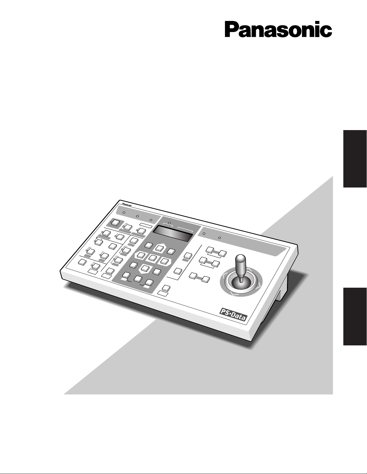
Model No. WV-CU360C
System Controller
Operating Instructions
System Controller WV-CU
360
C
O
PER
A
TE
LO
G
IN
A
LAR
M
M
O
N
IT
O
R
U
N
IT
C
AM
ER
A
BU
S
Y
PR
O
H
IBITE
D
S
H
IFT
FU
N
C
T
IO
N
C
AM
FU
N
C
TIO
N
P
RO
G
R
AM
ALM
R
E
SE
T
V
C
R
C
AM
MULTI SCREEN SELECT
STILL
–
SEQ PAUSE
SEQUENCE
SLOW
PATROL
LEARN
PROGRAM
PRESET
PATROL
STOP
ESC
SET
LOGOUT
MON
CAM
PATROL PLAY
+
A
U
X
1
W
IP
ER
H
O
M
E
/P
R
E
SE
T
AU
X
2
D
E
F
U
N
IT
B
ZO
O
M
W
ID
E
TE
LE
DOWN
L
R
UP
E
L
-Z
O
O
M
ALM RECALL
ALM
S
U
SP
E
ND
A
U
TO
FO
C
U
S
FAR
N
E
AR
U
N
IT
A
U
N
IT
B/W
SETUP
CAM SETUP
CLOSE
IRIS
OPEN
IRIS RESET
AUTO FOCUS
8
9
7
0
4
5
6
2
3
1
ENGLISH
FRANÇAIS
2
The serial number of this product may be found on the bottom of the unit.
You should note the serial number of this unit in the space
provided and retain this book as a permanent record of your
purchase to aid identification in the event of theft.
Model No.
Serial No.
WARNING:
To reduce the risk of fire or electric shock, do not expose this appliance to rain or moisture.
The lightning flash with arrowhead symbol, within an equilateral triangle, is
intended to alert the user to the presence of uninsulated "dangerous voltage"
within the product's enclosure that may
be of sufficient magnitude to constitute a
risk of electric shock to persons.
The exclamation point within an equilateral triangle is intended to alert the user
to the presence of important operating
and maintenance (servicing) instructions
in the literature accompanying the appliance.
CAUTION: TO REDUCE THE RISK OF ELECTRIC SHOCK,
DO NOT REMOVE COVER (OR BACK).
NO USER-SERVICEABLE PARTS INSIDE.
REFER SERVICING TO QUALIFIED SERVICE PERSONNEL.
CAUTION
RISK OF ELECTRIC SHOCK
DO NOT OPEN
SA 1965
SA 1966
NOTE: This equipment has been tested and found to comply
with the limits for a Class A digital device, pursuant to Part
15 of the FCC Rules. These limits are designed to provide
reasonable protection against harmful interference when the
equipment is operated in a commercial environment. This
equipment generates, uses, and can radiate radio frequency
energy and, if not installed and used in accordance with the
instruction manual, may cause harmful interference to radio
communications.
Operation of this equipment in a residential area is likely to
cause harmful interference in which case the user will be
required to correct the interference at his own expense.
FCC Caution: To assure continued compliance, (example use only shielded interface cables when connecting to computer or peripheral devices). Any changes or modifications
not expressly approved by the party responsible for compliance could void the user’s authority to operate this equipment.
For U.S.A
Caution:
Before attempting to connect or operate this product,
please read the label on the bottom.
ENGLISH VERSION

3
IMPORTANT SAFETY INSTRUCTIONS
1) Read these instructions.
2) Keep these instructions.
3) Heed all warnings.
4) Follow all instructions.
5) Do not use this apparatus near water.
6) Clean only with dry cloth.
7) Do not block any ventilation openings. Install in accordance with the manufacturer's instructions.
8) Do not use near any heat sources such as radiators, heat registers, stoves, or other apparatus (including amplifiers) that
produce heat.
9) Do not defeat the safety purpose of the polarized or grounding-type plug. A polarized plug has two blades with one wider
than the other. A grounding-type plug has two blades and a third grounding prong. The wide blade or the third prong are
provided for your safety. If the provided plug does not fit into your outlet, consult an electrician for replacement of the
obsolete outlet.
10) Protect the power cord from being walked on or pinched particularly at plugs, convenience receptacles and the points
where they exit from the apparatus.
11) Only use attachments/accessories specified by the manufacturer.
12) Use only with the cart, stand, tripod, bracket, or table specified by the manufacturer, or sold with the apparatus. When a
cart is used, use caution when moving the cart/apparatus combination to avoid injury from tip-overs.
13) Unplug this apparatus during lightning storms or when unused for long periods of time.
14) Refer all servicing to qualified service personnel. Servicing is required when the apparatus has been damaged in any way,
such as power-supply cord or plug is damaged, liquid has been spilled or objects fallen into the apparatus, the apparatus
has been exposed to rain or moisture, does not operate normally, or has been dropped.
ENGLISH
S3125A

4
CONTENTS
IMPORTANT SAFETY INSTRUCTIONS ............................ 3
PREFACE .......................................................................... 5
FEATURES ........................................................................ 5
PRECAUTIONS ................................................................. 5
MAJOR OPERATING CONTROLS & THEIR FUNCTIONS
.... 6
■ Rear View & AC Adapter ............................................ 6
INSTALLATIONS ............................................................... 7
■ Template Mounting .................................................... 7
■ Rear Panel Switch Setting (Summary) ....................... 8
Chapter 1
For Panasonic Security Data (PS
•
Data) Systems ........ 9
MAJOR OPERATING CONTROLS & THEIR FUNCTIONS
.... 10
■ Front View (Template for PS
•
Data) .............................10
INSTALLATIONS (PS
•
Data) .............................................. 13
■ System Connections .................................................. 13
■ DIP Switch Setting (PS
•
Data) ..................................... 15
■ Controller Number Setting (PS
•
Data) .........................16
CONTROLLER SETUP PROCEDURES (PS
•
Data) ............ 17
■ Prior to Setup ............................................................. 17
■ Buttons and Controls used in Setup........................... 17
■ Setup Menus .............................................................. 18
OPERATING PROCEDURES (PS
•
Data) ........................... 22
■ Basic Operating Flow.................................................. 22
■ Login/Logout............................................................... 23
■ System Unit Selection ................................................ 24
■ Monitor Selection ....................................................... 25
■ Camera Selection ....................................................... 25
■ Camera Control .......................................................... 26
■ Data Multiplex Unit Control ........................................ 28
■ Video Multiplexer Control ........................................... 29
■ Digital Disk Recorder Control .................................... 31
■ Alarm Operation ......................................................... 34
REMOTE SETUP of UNITS & CAMERAS .......................... 35
■ System Unit Setup ...................................................... 35
■ Camera Setup ............................................................ 35
■ Camera Patrol Learning ............................................. 36
■ Camera Preset Position .............................................. 37
Chapter 2
For WJ-FS616C Multiplexer System ............................. 39
MAJOR OPERATING CONTROLS & THEIR FUNCTIONS
.... 40
■ Front View (Template for WJ-FS616C) ....................... 40
INSTALLATIONS (For WJ-FS616C) .................................. 43
■ System Connections .................................................. 43
■ DIP Switch Setting ...................................................... 44
■ Controller Number Setting ......................................... 45
SETUP PROCEDURES (For WJ-FS616C) ......................... 46
■ Prior to Setup ............................................................. 46
■ Buttons and Controls used in Setup .......................... 46
■ Controller Setup ......................................................... 47
OPERATING PROCEDURES (For WJ-FS616C) ................ 49
■ Camera Selection ....................................................... 49
■ Camera Control .......................................................... 49
■ Alarm Operation ......................................................... 50
■ VTR (VCR) Control ..................................................... 50
■ Camera Setup ............................................................ 51
Chapter 3
For WJ-SX350 Matrix Switcher System ........................ 53
MAJOR OPERATING CONTROLS & THEIR FUNCTIONS
.... 54
■ Front View (Template for WJ-SX350) ......................... 54
INSTALLATIONS (For WJ-SX350) .................................... 57
■ System Connections .................................................. 57
■ DIP Switch Setting (For WJ-SX350) ........................... 58
■ Controller Number Setting ......................................... 59
CONTROLLER SETUP PROCEDURES (For WJ-SX350) .. 60
■ Prior to Setup ............................................................. 60
■ Buttons and Controls used in Setup .......................... 60
■ Setup Procedures ...................................................... 61
OPERATING PROCEDURES (For WJ-SX350) .................. 62
■ Login/Logout .............................................................. 62
■ Lens Control (Auto Focus Operation) ........................ 62
■ Pan/Tilt Control (Camera Position Operation) ............ 62
■ Pan/Tilt Control (Auto/Random Panning) ................... 63
■ Camera Housing Control ........................................... 63
Chapter 4
For WJ-SX850 Matrix Switcher System ........................ 65
MAJOR OPERATING CONTROLS & THEIR FUNCTIONS
.... 66
■ Front View (Template for System 850) ....................... 66
INSTALLATIONS (For System 850) .................................. 70
■ System Connections .................................................. 70
■ DIP Switch Setting ...................................................... 72
■ Controller Number Setting ......................................... 72
SETUP PROCEDURES (For System 850) ......................... 73
■ Prior to Setup ............................................................. 73
■ Buttons and Controls used in Setup .......................... 73
■ Setup Procedures ...................................................... 74
OPERATING PROCEDURES (For System 850) ................ 75
■ Log-in & Log-out ........................................................ 75
Appendix ......................................................................... 77
SPECIFICATIONS ............................................................. 78
STANDARD ACCESSORIES ............................................. 78
ALL RESET ....................................................................... 79

5
PREF ACE
The System Controller WV-CU360C is designed for setup
and operation of cameras and other system units installed
in a surveillance system.
The controller is compatible with the Panasonic Security
Data (PS
•
Data) protocol by default, but DIP switches are
provided to select the conventional communication protocol
used with the Video Multiplexer WJ-FS616C, Matrix
Switcher WJ-SX350 or WJ-SX850. Exchangeable templates
are supplied to adapt the names printed on the buttons to
the functions of the unit you wish to control.
You can operate a whole system from the controller, for
example, by selecting cameras and monitors, watching
monitor screens and indicators, and controlling pan/tilt, lens
and other camera functions.
FEATURES
Main features
• Camera channel selection
• Monitor Selection
• Alarm (Display/Suspend/Recall/Reset)
• Camera and system unit setup
Camera controls
• Lens functions: Iris/Focus/Auto Focus/Zoom
• Housing: Defroster/Wiper/Auxiliary 1, 2
• Pan/Tilt: Slow Pan/Slow Tilt/Auto Pan/Auto Sort/Auto
Sequence/Random Pan/Preset/Home/Camera Patrol
In a PS
•
Data or a WJ-FS616 system
• Switching of Live pictures and Playback/Changing the
Multiscreen Picture layout/Electronic Zoom/Sequence
• System Unit Selection
PRECAUTIONS
• Refer all work related to the installation of this
product to qualified service personnel or system
installers.
• Do not attempt to disassemble the appliance.
To prevent electric shock, do not remove screws or
covers.
There are no user-serviceable parts inside. Contact
qualified service personnel for maintenance.
• Handle the appliance with care.
Do not strike or shake, as this may damage the appliance.
• Do not expose the appliance to water or moisture,
nor try to operate it in wet areas.
Take immediate action if the appliance becomes wet.
Turn the power off and refer servicing to qualified service personnel. Moisture may damage the appliance
and cause electric shock.
• Do not use strong or abrasive detergents when
cleaning the appliance body.
Use a dry cloth to clean the appliance when it is dirty.
When the dirt is hard to remove, use a mild detergent
and wipe gently.
• Do not operate the appliance beyond its specified
temperature, humidity or power source ratings.
Do not use in the appliance in an extreme environment
where high temperature or high humidity exists.
Use the appliance at temperatures within –10˚C - +50˚C
(14˚F - 122˚F) and a humidity below 90 %. The input
power source for this appliance is 120 V AC 60 Hz by
use of the AC Adapter supplied.
• Do not use any AC adapter other than the one
supplied.
6
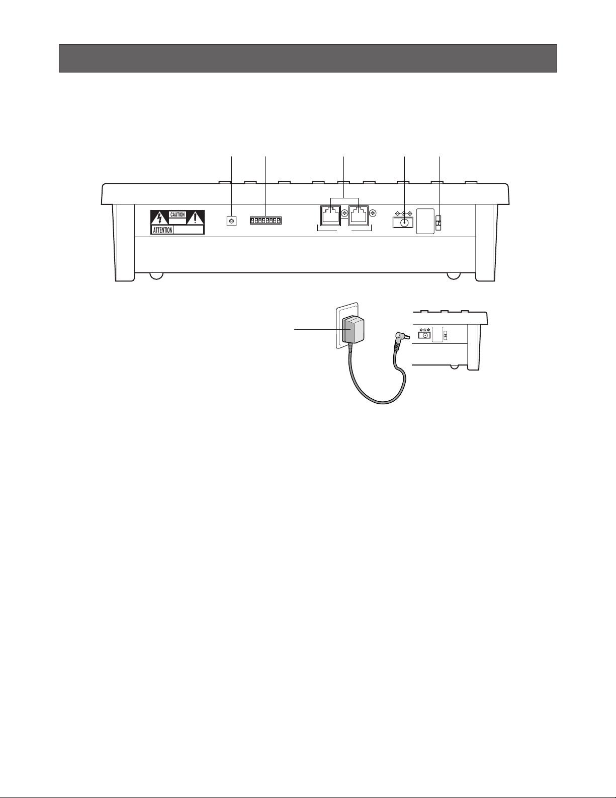
MAJOR OPERATING CONTROLS & THEIR FUNCTIONS
■ Rear View and AC Adapter
DC 9V IN
DATAMODE
RISK OF ELECTRIC
SHOCK. DO NOT OPEN
RISQUE DE CHOCS ELECTROUES
NE PAS OUVRIR
0
9
8
7
6
5
4
3
2
1
r te
CONTROLLER No.
w
q
q Controller Number Switch (CONTROLLER No.)
This switch is used to assign a controller number to the
System Controller to identify it in a system comprising
multiple System Controllers (See page 14). A system
may comprise up to four controllers.
w Mode Selection Switches (MODE)
The DIP switches are used to set communication parameters for the System Controller.
e Data Ports (DATA)
These ports are used to exchange control data with the
connected system units via the supplied RS-485 cable.
r DC 9 V Input Jack (DC 9V IN)
Jack for the DC plug of the supplied AC adapter.
t Clamp
The clamp fastens the power cord to the AC adapter.
y AC Adapter
Caution:
Use only the supplied AC adapter to feed DC 9 V to a
System Controller.
Note: Disconnect the plug from the controller before
setting the controller number switch or mode selection switch, and reconnect it when finished. The
new settings will take effect when the power is
turned on.
DC 9V IN
y
7
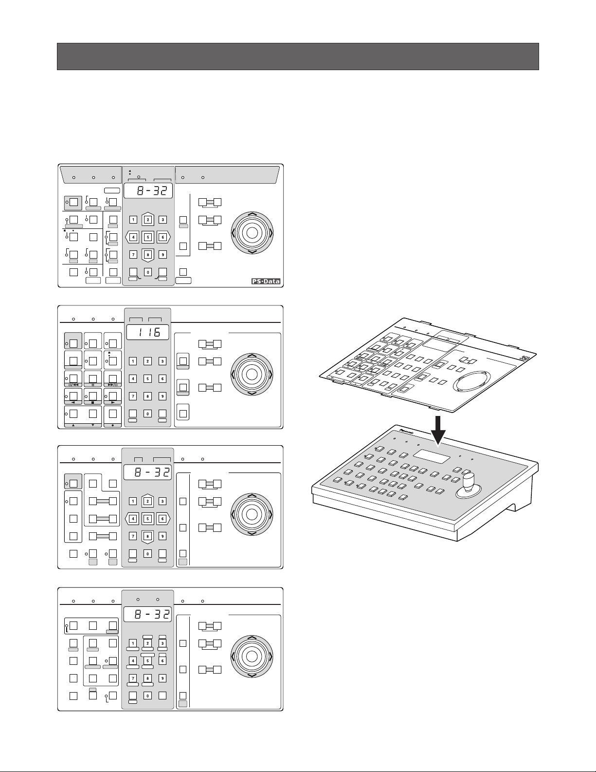
INSTALLA TIONS
■ Template Mounting
The system controller is provided with four templates
including one for PS
•
Data system that is placed (not taped
yet) on the surface of the controller when shipped from the
factory.
1. Select the correct template for your system.
• Select the PS
•
Data template when your system
includes any of the following:
Video Multiplexer (WJ-FS309/316)
Digital Disk Recorder (WJ-HD100/500A)
Data Multiplex Unit (WJ-MP204C)
• Select the template marked “For Multiplexer” if your
system includes a WJ-FS616C Video Multiplexer.
• Select the template marked “For Matrix Switcher” if your
system includes a WJ-SX350 Matrix Switcher.
• Select the template marked “For Matrix Switcher
(System SX850)” if your system includes a WJ-SX850
Matrix Switcher.
2. Peel off the tape, and fix the template in the guide slots
on the front panel of the controller.
OPERATE LOGIN ALARM
CAM SETUP
PROGRAM
PROGRAM
PRESET
UNIT A
IRIS
CLOSE OPEN
NEAR FAR
WIDE TELE
FOCUS
ZOOM
AUTO FOCUS
IRIS RESET
AUTO
SETUP
ALM SUSPEND
FUNCTION
CAM FUNCTION
MULTI SCREEN SELECT
DEF
WIPER
EL-ZOOM
SHIFT
ALM RESET
VCR CAM
STILL
–
+
ALM RECALL
PATRO L
LEARN
PATRO L
STOP
AUX 1
AUX 2
B/W UNIT
SEQ PAUSE
SLOW
SEQUENCE
PATROL PLAY
HOME/PRESET
UNIT B
MON
CAM
LOGOUT
ESC SET
UP
LR
DOWN
BUSY PROHIBITED
MONITOR
UNIT
CAMERA
System Controller
WV-CU C
360
AUTO FOCUS
OPERATE LINK ALARM BUSY PROHIBITED
IRIS
CLOSE OPEN
NEAR FAR
WIDE TELE
FOCUS
ZOOM
IRIS RESET
PREV
SEQ
SEQ
TOUR
GROUP
ALARM
DISARM
ACK
RESET
GROUP PRESET
NEXT
LOG OUT PAUSE STOP
F1
F2 MONITOR
CAM FUNC LOCK
OSD SERVICE
CAMERA
(ENTER)
CLEAR
(ESC)
CALL
PRESET
PROGRAM
PRESET
SHIFT
DEF OFF DEF ON
AUX2 OFF AUX2 ON
AUX1 OFF AUX1 ON
CAM ID
OPE ID S-CTL ID
OSD
CAM MENU OFF CAM MENU ON
ALL RESET
MDN STATUS
WIPER
GEN
ALL
EXITBLK
VLD HALM H
VLD S SYS SALM S
AUTO
PAN
UP
LR
DOWN
For Matrix Switcher (System 850)
WV-CU C
360
CAMERA SITE CONTROL
System Controller
MONITOR CAMERA
SEQ
HISTORY
AUTO FOCUS
OPERATE LOGIN ALARM BUSY PROHIBITED
AUX
IRIS
CLOSE OPEN
NEAR FAR
TELE WIDE
FOCUS
ZOOM
IRIS RESET
BACK
-1 CAM
DEC
+1 CAM
INC
FWD
BACK
ALT PAUSE FUNCTION
ACK/RESET FWD
ALL RESET
RECALL
STATUS
PRESET
POSI
PAN
MON
CAM
ESC SET
CAM
POSI
UP
LR
DOWN
MONITOR CAMERA
For Matrix Switcher
WV-CU C
360
CAMERA SITE CONTROL
System Controller
SETUP
CAM
MENU
System Controller
OPERATE LOCK ALARM
SPOT
AUTO/+
IRIS
CLOSE OPEN
NEAR FAR
TELE WIDE
FOCUS
ZOOM
IRIS RESET
VTR
CAM
MULTI
SCREEN
SEQUENCE
EL-ZOOM
MULTI SELECT
STILL
PRE-POSI
ALT
ALM RESET
ALM SUSPEND
FUNCTION
ALL RESET
CAMERA SET
ON OFF ON/OFF
SETUP
AUTO
FOCUS
HOME/-
UNIT
CAM
ESC SET
UP
LR
DOWN
UNIT CAMERA
For Multiplexer
WV-CU C
360
T/L MODE
CAMERA SITE CONTROL
AUX 2
AUX 1
OPERATE
LOCK
ALARM
AUTO/+
IRIS
C
L
O
S
E
O
P
EN
N
E
AR
FA
R
TE
LE
W
ID
E
FOCUS
ZOOM
SPOT
MULTI SELECT
VTR
CAM
ALT
FUNCTION
ALM RESET
ALM SUSPEND
ALL RESET
S
E
Q
U
E
N
C
E
PRE-POSI
EL-ZOOM
MULTI
SCREEN
IRIS RESET
CAMERA SET
SET UP
STILL
ON/OFF
OFF
ON
AUTO
FOCUS
HOME/-
U
N
IT
CAM
ESC
SET
CAMERA SITE CONTRIL
UP
L
R
D
O
W
N
CAMERA
UNIT
System Controller
For Multiplexer
WV
-
CU
AUX 2
AUX 1
T/L MODE
2
5
8
0
3
6
9
1
4
7
8
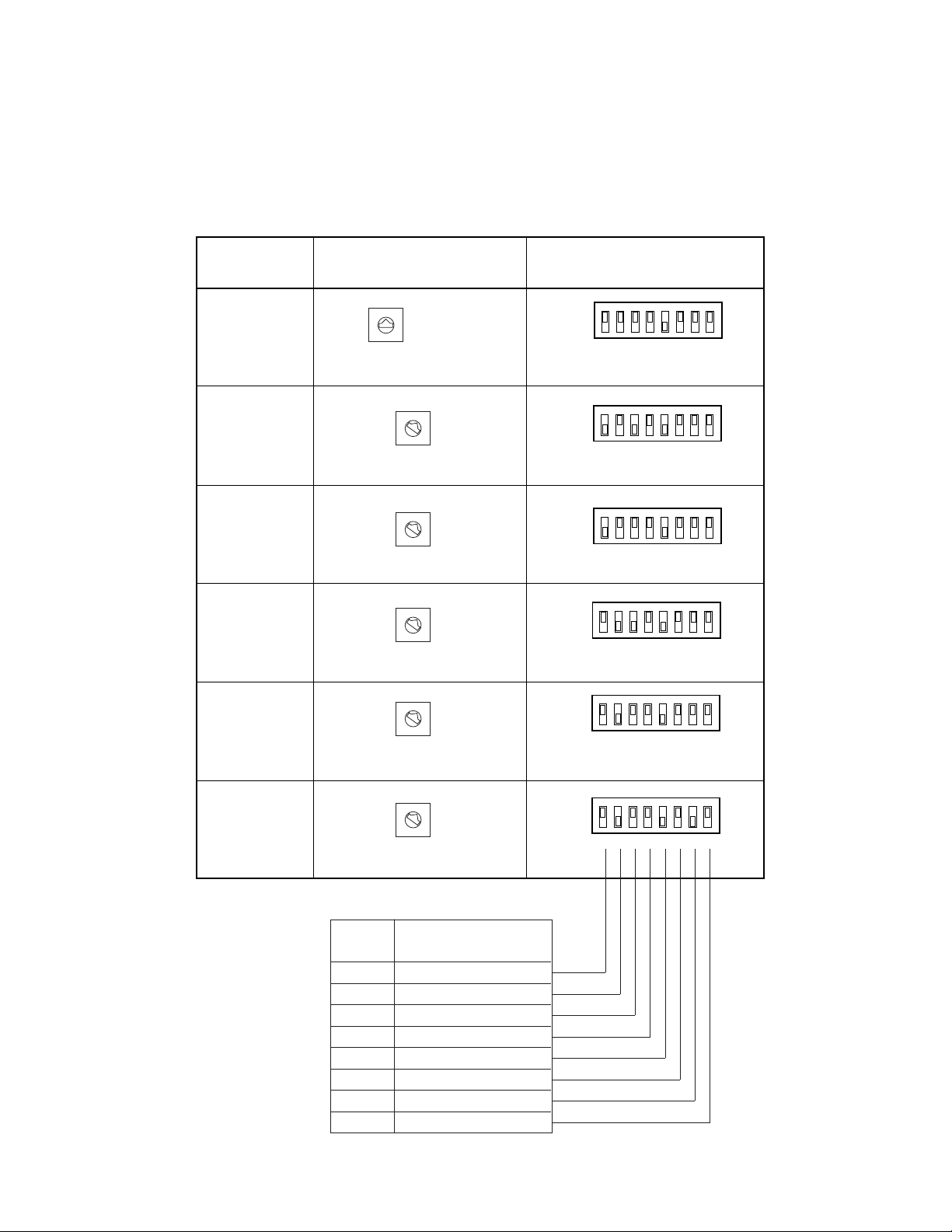
■ Rear Panel Switch Setting (Summary)
An 8-bit DIP switch and a rotary switch mounted on the rear of the controller specify the system unit ID and parameters for
communication. Switch settings depend on your system configuration such as a PS
•
Data system, WJ-FS616C Multiplexer system, WJ-SX350 Matrix Switcher system or System 850. A summary of switch positions is shown below. For detailed information
refer to the description of switch settings provided for each system.
MODE
12345678
OFF
ON
0
9
8
7
6
5
4
3
2
1
CONTROLLER No.
System
Controller No. SW
MODE DIP SW
PS•Data
MODE
12345678
OFF
ON
WJ-FS616C
MODE
12345678
OFF
ON
CONTROLLER No.
WJ-FS616
MODE
12345678
OFF
ON
CONTROLLER No.
WJ-SX350
(Ver. 6.00
or later)
MODE
12345678
OFF
ON
CONTROLLER No.
WJ-SX350
(Ver. 1.xx)
MODE
12345678
OFF
ON
CONTROLLER No.
System 850
WJ-SX850
0
9
8
7
6
5
4
3
2
1
CONTROLLER No.
#1
#1
#1
#1
#1
0
9
8
7
6
5
4
3
2
1
0
9
8
7
6
5
4
3
2
1
0
9
8
7
6
5
4
3
2
1
0
9
8
7
6
5
4
3
2
1
See page 16
Function
Bit 3
Bit 2
Bit 1
Bit 4
Bit 5
Bit 6
Bit 7
Bit 8
System Unit ID
System Unit ID
System Unit ID
Reserved
Line termination
Operation mode
Baud rate selection
Data transmission mode

9
Panasonic Security Data (PS•Data) Systems

10
MAJOR OPERATING CONTROLS & THEIR FUNCTIONS
■ Front View (Template for PS•Data)
q Operate indicator (OPERATE)
Is lit while power is supplied to the System Controller.
w Login indicator (LOGIN)
Lights up when communication is established with
PS
•
Data compatible system units.
e Alarm indicator (ALARM)
Blinks when an alarm is activated.
Blinking changes to steady light when the alarm is automatically reset.
To turn the indicator off, press the Alarm Reset button.
r Monitor/Unit indicator ( MONITOR/ UNIT)
When this indicator lights up, the monitor number is displayed. When it goes off, the unit address is displayed.
t LED Display
LED display allowing you to confirm the monitor or unit
number and the number of the currently controlled
camera.
It also displays numeric input, error status, etc.
The monitor or unit number is displayed when initial
communication is established.
y Busy indicator (BUSY)
Lights up when you attempt to control a system unit or
camera that is already used by a higher priority operator, or when a higher priority operator selects the camera or system unit you are currently operating.
Operations from the System Controller are disabled
until this indicator goes off.
u Prohibited indicator (PROHIBITED)
Lights up when an attempt is made to access a function
that is prohibited to the operator level.
i Joystick Controller (UP/DOWN/L/R)
Used to manually operate the pan/tilt head, or move the
cursor in the setup menu on the active monitor screen.
The joystick can also be moved in 8 directions.
Holding down the joystick in the desired position will
keep the cursor moving continuously in the setup menu.
(See page 17.)
UP: Upward
DOWN: Downward
L: Left
R: Right
OPERATE LOGIN ALARM
CAM SETUP
PROGRAM
PROGRAM
PRESET
UNIT A
IRIS
CLOSE OPEN
NEAR FAR
WIDE TELE
FOCUS
ZOOM
AUTO FOCUS
IRIS RESET
AUTO
SETUP
ALM SUSPEND
FUNCTION
CAM FUNCTION
MULTI SCREEN SELECT
DEF
WIPER
EL-ZOOM
SHIFT
ALM RESET
VCR CAM
STILL
–
+
ALM RECALL
PATROL
LEARN
PATROL
STOP
AUX 1
AUX 2
B/W UNIT
SEQ PAUSE
SLOW
SEQUENCE
PATROL PLAY
HOME/PRESET
UNIT B
MON
CAM
LOGOUT
ESC SET
UP
LR
DOWN
BUSY PROHIBITED
MONITOR
UNIT
CAMERA
System Controller
WV-CU C
360
@6
@5
@0
!8
!9
@7
#0
@9
@8
wqertyu i
!1 !0 o!4!5!6!7@3
@4
!3!2@1
@2
#2
#1

11
o Iris buttons (IRIS, CLOSE/OPEN)
Close or open the lens iris of cameras equipped with
the specified lens.
When these buttons are pressed simultaneously, the
lens iris is reset to the factory default setting.
!0 Focus buttons (FOCUS, NEAR/FAR)
Adjust the lens focus of cameras equipped with the
specified lens.
When these buttons are pressed simultaneously, the
lens focus is set automatically if the specified camera is
used.
!1 Zoom buttons (ZOOM, WIDE/TELE)
Zoom the image in or out if the camera is equipped with
the specified lens.
!2 Unit A/UNIT button (UNIT A/UNIT)
Selects a specific system unit in a multiple unit system.
To select a unit, press this button after entering the unit
number with the numeric button. To confirm a unit number, press this button after pressing the SHIFT button.
The selected unit address appears on the LED display.
The unit that is assigned to number 1 can be selected
by pressing this button.
!3 Unit B button (UNIT B)
Selects a specific system unit in a multiple unit system.
To select a unit, press this button after entered the unit
number with the numeric button. The selected unit
address appears on the LED display.
Just pressing this button will select the system unit
assigned the number 1.
!4 Home/Preset/Programme Preset button
(HOME/PRESET/PROGRAM PRESET)
Returns a specific camera to its home position.
In combination with the numeric buttons, this button is
also used to recall a preset position assigned to a specific camera.
Pressing it while holding down the Programme/Camera
Setup/Camera Function button will programme the preset position.
!5 Numeric buttons (0-9)
These buttons are used for numeric input, such as camera, monitor and unit numbers, and preset positions.
!6 Camera/Set button (CAM/SET)
CAM: Used for camera selection. To select a camera,
enter the desired camera number with the numeric
buttons, and then press this button.
SET: Executes the currently highlighted setting in the
setup menu.
Pressing this button together with the MON/ESC button
for approximately 2 seconds will log out from the system.
!7 Monitor/Escape button (MON/ESC)
MON: Used for monitor selection and confirmation. To
select a monitor, enter the desired monitor number
with the numeric buttons, and then press this button. The selected monitor number appears on the
LED display.
To confirm a monitor number, simply press this button.
ESC: Used to escape from the currently highlighted
selection and return to the previous menu of the
setup menu.
Pressing this button together with the CAM/SET button
for approximately 2 seconds will log out from the system.
!8 Programme/Camera Setup/Camera Function button
(PROGRAM/CAM SETUP/CAM FUNCTION)
Programmes camera patrol learning and preset position
functions.
Pressing this button for 2 seconds or more will open the
camera setup menu. Pressing it in combination with the
numeric buttons after pressing the shift button will execute camera functions.
The LED next to the button is lit during the camera
setup operation.
!9 Setup/Function button (SETUP/FUNCTION)
Pressing this button for 2 seconds or more will open the
setup menu of a system unit.
When the SHIFT indicator is lit, it provides access to the
functions of the system unit. Enter a function number
with the numeric keys, then press this button.
The LED next to the button is lit during the setup operation.
@0 Shift button (SHIFT)
Shifts the button function between the normal and the
shift mode shown in half-tone print under the button on
the template. The LED next to the button is lit in the
shift mode.
@1 Auto Panning/Black and White button (AUTO/B/W)
Activates the auto panning function of cameras provided with this feature. Pressing this button in the shift
mode will change the camera picture from color to
black and white for better viewing in a dark place.
AUTO PAN ON or combination camera function:
Simply press this button, or press numeric button 1
followed by this button.
AUTO SORT ON: Press numeric button 2 followed by
this button.
AUTO SEQ ON: Press numeric button 3 followed by
this button.
RANDOM PAN ON: Press numeric button 4 followed by
this button.

12
@2 Defroster/Auxiliary 2 button (DEF/AUX 2)
Activates the housing defroster of cameras provided
with this feature. Pressing this button in the shift mode
will turn on the AUX 2 function controlling accessories
connected to the cameras or the system.
The LED next to the button is lit while the defroster or
AUX 2 function operates.
@3 Wiper/Auxiliary 1 button (WIPER/AUX 1)
Activates the housing wiper of cameras provided with
this feature. Pressing this button in the shift mode will
turn on the AUX 1 function controlling accessories connected to the cameras or the system.
The LED next to the button is lit while the wiper or AUX
1 function operates.
@4 Patrol Play/Patrol Learn button (PATROL PLAY/
PATROL LEARN)
Starts the camera patrol play. While holding down the
Programme/Camera setup/Camera Function button,
pressing this button will start to programme the camera
patrol learning.
@5 Alarm Suspend button (ALM SUSPEND)
Suspends or allows the alarm process.
The LED next to the button is lit while the alarm suspension mode operates.
@6 Alarm Reset/Alarm Recall button (ALM RESET/ALM
RECALL)
Resets system alarm when the alarm function is active.
Pressing this button in the SHIFT mode will recall the
alarm logs (record of alarms activated in the past).
Select a monitor, and then press this button to display
the alarm logs on the monitor screen. Pressing this button after pressing the shift button again will cancel the
function.
The LED next to the button is lit while Alarm Recall
mode is activated.
@7 Multiscreen Selection button (MULTI SCREEN
SELECT)
Selects the number of segments into which the multiscreen is split on the selected monitor connected to the
MULTISCREEN OUT terminal of the Video Multiplexer.
@8 VCR/Camera Selection button ( VCR/ CAM)
Changes the display on the multiscreen monitor
between the live picture of a camera and the playback
picture of a recording device. The LED next to the button is lit while VCR is selected.
@9 Electronic Zoom/Increment button (EL-ZOOM/+)
Zooms the camera picture or VCR playback picture displayed on the multiscreen monitor.
Pressing this button in the shift mode will move the
camera sequence one step forward from the step previously paused while a system unit provided with SEQ
PAUSE (e.g., a Video Multiplexer) is selected.
Pressing this button in the shift mode will select the picture of camera with the next higher number for display
on the monitor while a system unit connected with cameras (e.g., a Data Multiplex Unit) is selected.
The LED next to the button is lit while Electronic Zoom
mode is selected.
#0 Still/Decrement button (STILL/–)
Freezes the camera picture or VCR playback picture on
the multiscreen monitor.
Pressing this button in the shift mode will move the
camera sequence one step backward from the step
previously paused while a system unit (e.g., a Video
Multiplexer) provided with SEQ PAUSE is selected.
Pressing this button in the shift mode will select the picture of the camera with the next lower number for display on the monitor while a system unit connected with
cameras (e.g., a Data Multiplex Unit) is selected.
The LED next to the button is lit while a still picture is
displayed.
#1 Sequence/Patrol Stop button (SEQUENCE/PATROL
STOP)
Runs or stops a preset sequence in which a series of
camera pictures is displayed in succession on the monitor screen for the specified duration. Pressing it while
holding down the Programme/Camera Setup/Camera
Function button will stop programming of camera patrol
learning.
The LED next to the button is lit while a sequence runs.
#2 Sequence Pause/Slow button (SEQ PAUSE/SLOW)
Pauses a sequence running on the selected monitor. In
this mode, a series of camera pictures is displayed in
pause on the monitor screen for the specified duration.
Pressing this button while moving the joystick controller
will decrease the pan/tilt speed.
13
INSTALLA TIONS (PS•Data)
The installation should be made by qualified service personnel or system installers according to the following instructions.
CAUTION
■ System Connections
● Connection Example
Example 1 shows 8 cameras connected to 2 Data Multiplex Units (WJ-MP204C), to a Video Multiplexer (e.g., WJ-FS316) and a
Digital Disk Recorder (e.g., WJ-HD100). The WV-CU360C controls these system units through RS-485 communication while
pictures are viewed on the monitors.
SIGNAL
GND
ALARM/REMOTE
OUT
IN
VIDEO
16 15 14 13 12 11 10 9 8
16 15 14 13 12 11 10 9 8
7654 21
76543321
PLAY IN
REC OUT
SPOT OUT
DATA
CAMERA
SW IN
MULTI
SCREEN OUT
SD RD
IN IN
CAMERA RS485
ABABG
VS/VDSPOT DATA
ALARM / REMOTE
MODE
SIGNAL GND
4321
OUT OUTINOUT
4321
TR
IN IN
CAMERA RS485
ABABG
VS/VDSPOT DATA
ALARM / REMOTE
MODE
SIGNAL GND
4321
OUT OUTINOUT
4321
Camera No. 1
Camera No. 2
Camera No. 3
Camera No. 4
Camera No. 5
Camera No. 6
Camera No. 7
Camera No. 8
VS/VD INPUT
Unit Address 1Unit Address 2
WJ-MP204C
WJ-MP204C
WJ-FS316
WJ-HD100
Unit Address 3
Unit Address 4
Video Signal
6-conductor Modular Cable (supplied)
Termination ON
MODE
VS/VD OUTPUT
4-Line
Monitor No. 1
Monitor No. 2
Panasonic Security
Data mode
Termination OFF
Panasonic Security
Data mode
4-Line
MODE
VD OUT
RS-485 Signal
(Panasonic Security
Data Mode)
SIGNAL GND
ALARM
SERIES
RECORD
TIME
ADJUST
REMOTE
MODEDATARS-232CVIDEO
OUT
IN
OUT
IN
AUDIO
MONITOR OUT
(PLAY)
CAMERA
SW OUT
G
G
G
POWER
ON
OFF
JOG-CLICK
JOG-LEFT
JOG-RIGHT
ALARM SEARCH
STEP
REW/FF
STOP/SETUP
PLAY
REC
OUT
PLAY OUT
REC OUT
AUTO OFF OUT
DISK END OUTINOUTINRECALL
(EXT REC)
OUT
RECOVER OUT
RESET IN
IN
PLAY INPLAY
VIDEO IN REC OUT
RS-485 Cable
Branch
Cable
Up to four WV-CU360C
can be used in a system.
DC 9V IN
DATAMODECONTROLLER No.
0
9
8
7
6
5
4
3
2
1
0
9
8
7
6
5
4
3
2
1
Keep in OFF position
Keep in OFF position
Termination ON
Set to OFF position
(for operator mode)
Controller No. 1
Refer to DIP switch setting on page 15
CONTROLLER No.
14
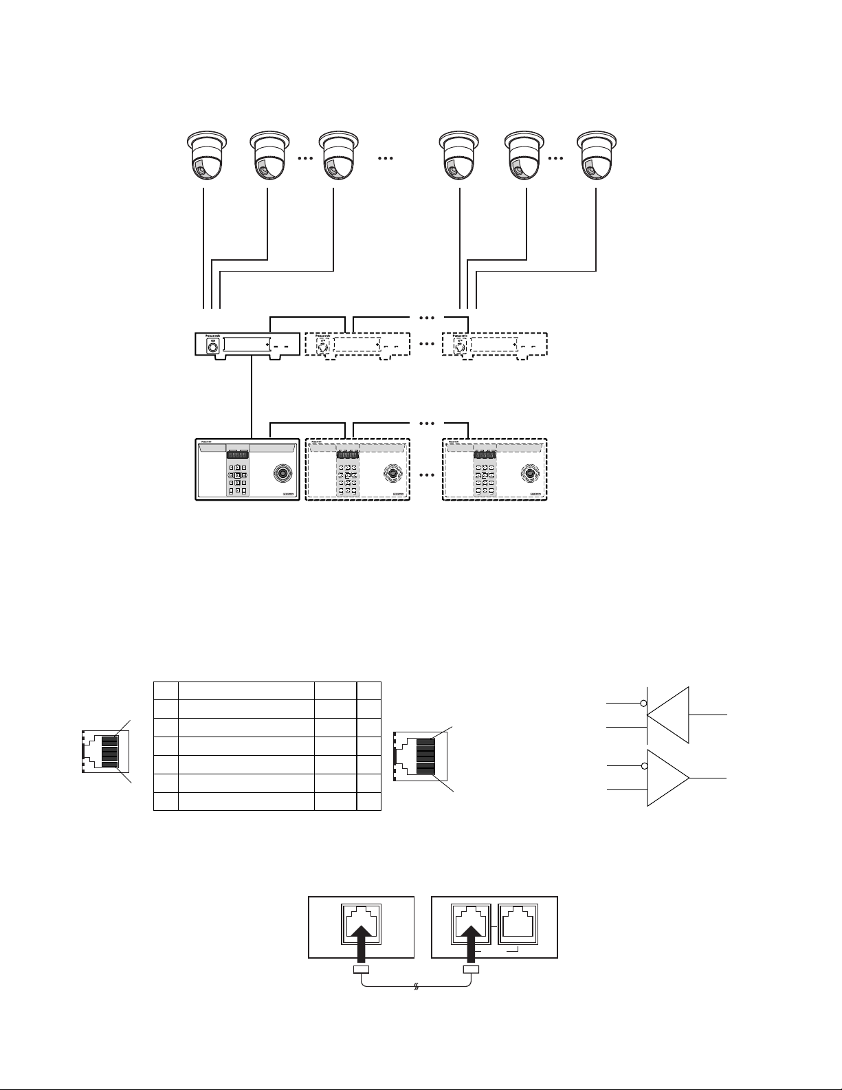
● DATA Port Connection (PS•Data)
Data ports are connected with RS-485 cables among devices using the PS•Data protocol as follows.
Notes: When using cables other than those supplied, make sure to use shielded 4-wire twisted pair cable suitable for RS-485
communication.
• Internal Diagram
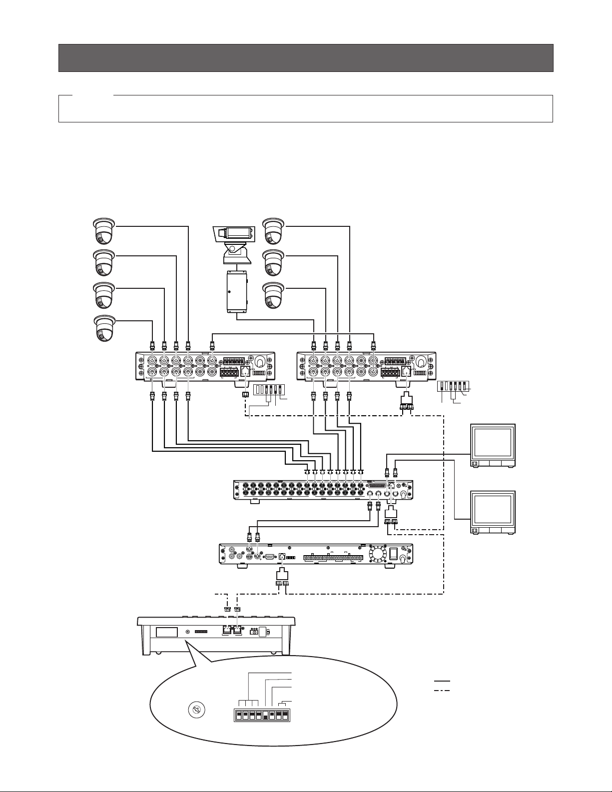
• Basic Connection
Example 2 shows 4 Data Multiplex Units connected with 16 combination cameras, and 4 System Controllers.
System Controller
WV-CU
360
System Controller
WV-CU
360
UP
LR
DOWN
System Controller
WV-CU
360
Data Multiplex Unit WJ-MP204C Data Multiplex Unit WJ-MP204 Data Multiplex Unit WJ-MP204
WJ-MP204C
WV-CU360C
4 cameras can be connected to one Data Multiplex Unit
UP
LR
DOWN
UP
LR
DOWN
Up to 4 Data Multiplex Units
Up to 4 System Controllers
Channel 1 Channel 2 Channel 4 Channel 13 Channel 14 Channel 16
Unit
address 1
Controller
No. 1
Controller No. 2 Controller No. 4
Unit
address 2
Unit
address 4
See page 16 for MODE switch and
CONTROLLER NO. switch settings.
No. No.
1 1
1
2 2
3 3
4 4
6
5 5
6 6
Data Flow
–
WJ-MP204C ← WV-CU360C
WJ-MP204C ← WV-CU360C
WJ-MP204C → WV-CU360C
WJ-MP204C → WV-CU360C
–
Termination:
ON
Name
GND
TX(B)
TX(A)
RX(B)
RX(A)
GND
Data Multiplex Unit
WJ-MP204C
DATA
Controller end
RS-485 Cable
1
6
System Controller
WV-CU360C
DATA
TX (B)
TX (A)
RX (B)
RX (A)
Termination:
ON
15
SW position
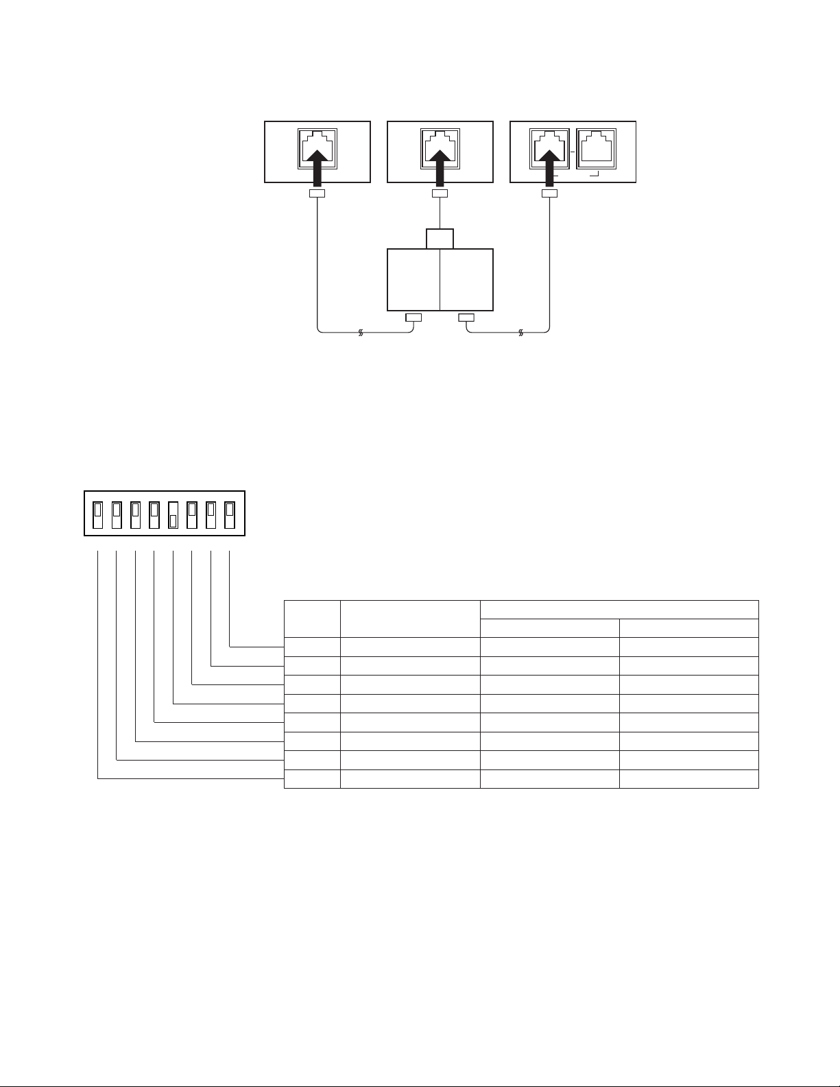
• Daisy Chain Connection
■ DIP Switch Setting (PS•Data)
An 8-bit DIP switch mounted on the rear panel specifies the communication mode, etc. The default position is marked with an
asterisk *.
OFF
Not used
Function
ON
Bit 6
Bit 7
Bit 8
Bit 5
Bit 4
Bit 3
Bit 2
Bit 1
Operation mode
Baud rate selection
Data transmission mode
Line termination
Reserved
System Unit Version
System Unit Version
System Unit Version
Operator*
Fixed to OFF*
Fixed to OFF*
Off
Fixed to OFF*
Fixed to OFF*
Fixed to OFF*
Fixed to OFF*
Administrator
Not used
Not used
On*
Not used
Not used
Not used
1. Remove the DC plug from the rear of the controller.
2. Set the switch referring to the table.
3. Connect the DC plug to the controller.
Notes:
• Bits 1 - 4 are reserved.
• Bit 5 opens or terminates the communication chain. The switch should be set to OFF when the controller is located in an
intermediate position.
• Bit 6 specifies the operation mode, Operator or Administrator. The switch should be set to Administrator when setting up
the controller. Remember to set this switch to the right position after completion of the setup operation.
• Bits 7 and 8 are used in the OFF position.
Video Multiplexer
WJ-FS309 (WJ-FS316)
Termination:
ON
RS-485
Cable
Data Multiplex Unit
WJ-MP204C
Termination:
OFF
DATA
Branch
Cable
System Controller
WV-CU360C
DATA DATA
Termination:
ON
RS-485
Cable
OFF
ON
12345678
MODE

16
● MODE Switch Setting for System Example 2
The MODE switch needs to be set prior to operating a system connected as shown in Example 2.
Bit 3 should be set to OFF.
Bit 5 should be set to OFF when the controller is placed
in an intermediate position, or set to ON when it is connected at the chain end.
■ Controller Number Setting (PS•Data)
A 10-position rotary switches provided on the rear for specifying the unit number of the WV-CU360C controller in a
PS
•
Data system.
1. Remove the DC plug from the rear of the controller.
2. Use a screw driver to rotate the switch so that the arrow
comes to the number you wish.
3. Connect the DC plug to the controller.
Notes:
• Set the switch to #1 when a single controller is used in
the system.
• Specify a unique number for each controller when connecting multiple controllers in the system. One controller within the multiple controller system must be
assigned the number 1.
• Positions #0 and #9 are reserved and cannot be used.
Controller No. Switch of WV-CU360C Controller No.
0 Reserved
11
22
33
44
55
66
77
88
9 Reserved
OFF
ON
12345678
0
1
9
2
8
3
7
4
6
5
CONTROLLER No.

17
CONTROLLER SETUP PROCEDURES (PS
•
Data)
To display the setup menus for the WV-CU360C System Controller on the LED display, set the MODE switch and power up the
controller as described below.
■ Prior to Setup
Do the following before entering the setup mode.
1. Confirm that all necessary connections and switch settings are complete.
2. With the power turned off, move bit #6 of the MODE
switch on the rear to ON (administrator) position.
3. Supply power to the controller.
4. Turn on the power of cameras and other system units.
5. The LCD displays [SEtUP]. The controller is ready to
enter the setup mode.
When setup is completed, restore the switch to its original
position.
1. With the power turned off, move bit #6 of the MODE
switch on the rear to OFF (operator) position.
2. Supply power to the controller.
■ Buttons and Controls used for Setup
The following buttons and joystick operations are used in
the setup operation. There are three ways to select a parameter, but the following pages only describe the selection
by use of the joystick. Instead of operating the joystick, you
can enter the number enclosed in brackets with the numeric keys or press the plus and minus buttons.
0
9
Numeric buttons: To select a parameter
To enter a password or
parameter
CAM/SET button: To confirm the selected
menu, selected parameter or entered password
To enter a submenu
MON/ESC button: To return to the previous
menu
CAM
SET
MON
ESC
DOWN
LR
UP
LR
UP
DOWN
R
UP
DOWN
LR
Up: To select a setup menu
Down: To select a setup menu
Left: To decrease the parameter
Right: To increase the parameter
EL-ZOOM
STILL
–
+
or
or
18
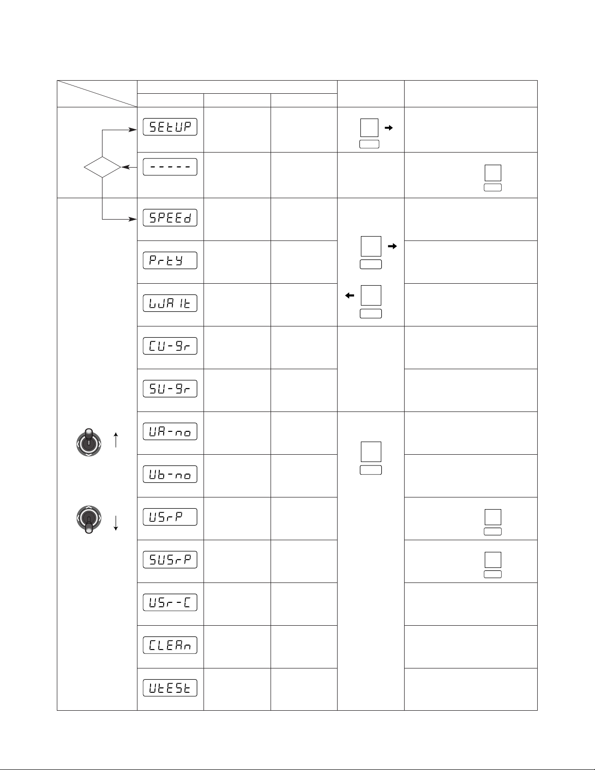
■ Setup Menus
There are 12 setup menus as shown below.
Menu
Selection
Move Joystick up
and down to select
Setup Menus
Parameter Selection (default*)
LED Display
blinking
Setup
Administrator
Password
Prompt
Speed
Parity
Wait
Controller
Unit
Group
System
Unit
Group
Unit A
Number
Unit B
Number
User
Password
Super
User
Password
User
Certification
Cleaning
Unit
Test
Initial
Display
Authorization
Baud Rate
(bps)
Press
twice
Parity Check
Wait Time
(ms)
Unit
Assignment to
Button A
Unit
Assignment to
Button B
Administrator
Password
User
Authorization
Camera
Cleaning
Unit Connection
Test
CAM
SET
CAM
SET
MON
ESC
CAM
SET
LED prompts you to enter a password
Enter a 5-digit
password, press
(12345*)
(1) 2 400 (2) 4 800 (3) 9 600*
(4) 19 200
(1) None* (2) Even
(1) Off* (2) 100 (3) 200 (4) 400
(5) 1 000
Leave as it is
Leave as it is
Enter a 5-digit
number, press
(12345*)
Reading Function
OK
No
DOWN
LR
UP
LR
CAM
SET
CAM
SET
Enter a 5-digit
number, press
(12345*)
(1) Off (2) On*
CAM
SET

19
● Administrator Authorization
1. Press the CAM/SET button while [SEtUP] is displayed.
The [- - - - -] prompt appears.
2. Enter a password with the numeric buttons, then press
the CAM/SET button.
The default setting is [12345].
3. [SPEED] appears when the right password is entered. If
password entry failed, the menu returns to [- - - - -].
Notes:
• We recommend that you register a new password different from “12345” in [SUSrP], and note down the registered password for future reference.
• Powering up the controller while holding down numeric
buttons 2, 4 and 5 simultaneously will reset the password to “12345”. Remember that this procedure also
resets all other menu parameters to the default settings.
● Baud Rate
In this menu, the communication speed (bps: bits per second) is selected. The communication speed should match
that of the other units connected in the communication
chain.
1. Display [SPEED] and press the CAM/SET button twice.
2. Select a parameter entering a bracket-enclosed number, e.g., (3), moving the joystick right and left, or
pressing the [+] and [–] button.
The default setting is 19 200 bps.
(1) 2 400: 2 400 bps
(2) 4 800: 4 800 bps
(3) 9 600: 9 600 bps
(4) 19 200: 19 200 bps
Note: Selecting a slower rate (e.g., 2 400 bps) will
delay the response time (e.g., the time until an activated alarm is reset).
3. Press the CAM/SET button to validate the selection.
4. Press the ESC button to go back to the previous menu.
● Parity
In this menu, the parity check mode is selected.
1. Display [PrtY] and press the CAM/SET button twice.
2. Select a parameter with the joystick.
The default setting is None.
n: None
E: Even parity
3. Press the CAM/SET button to validate the selection.
4. Press the ESC button to go back to the previous menu.
● Wait Time
In this menu a wait time is selected. The controller will
retransmit data when there is no response during the specified wait time.
1. Display [LJAit] and press the CAM/SET button twice.
2. Select a parameter with the joystick.
The default setting is Off.
(1) OFF: Off, no retransmission of data
(2) 100: 100 ms
(3) 200: 200 ms
(4) 400: 400 ms
(5) 500: 500 ms
(6) 1 000: 1 s
3. Press the CAM/SET button to validate the selection.
4. Press the ESC button to go back to the previous menu.
The following two menus should be maintained in the
default condition.
● Controller Unit-Group Address
[CU-gr] appears on the Setup menu, but leave the
default as it is.
● System Unit-Group Address
[SU-gr] appears on the Setup menu, but leave the
default as it is.

20
● Unit A button Assignment
In this menu, a maximum of 9 system units is assigned to
numeric buttons 1-9 regardless of unit address.
This is to avoid double-digit unit addresses which can
occur in a large system with many units connected and
could confuse operators.
A frequently used system unit can be easily selected in normal operation by pressing one numeric button and then the
UNIT A button.
1. Display [UA-no] and press the CAM/SET button. The
LED displays [A1-01] while “1” following A blinks.
The first 2 digits from A1 to A9, “A numbers”, stand for
numeric buttons from 1 to 9 to be pressed prior to UNIT
A button in normal operation. The next 2 digits are the
unit address assigned in the following procedures.
The default setting is shown below.
A1-01
A2-02
A3-03
A1-04
A5-05
A6-06
A7-07
A8-08
A9-09
2. Select an “A number” entering a number from 1 to 9,
then press the CAM/SET button. The LED displays “A
number” A3 when numeric button 3 is entered for
example.
Available A numbers: 1-9
3. Press the CAM/SET button to validate the selection. The
LED displays [A3-03] while the next two digits are blinking.
4. Enter a 2-digit unit address that you wish to assign to
the “A number” (e.g., A3), then press the CAM/SET button. The LED displays [A3-99], for example, when you
enter unit address 99.
Available addresses: 01-99
5. Press the CAM/SET button to validate the selection.
Repeat above the steps 2 to 5 as needed.
6. Press the ESC button to go back to the previous menu.
● Unit B button Assignment
The UNIT B button is set up in the same way as the UNIT A
button for use in normal operation. Refer to the above
description for Unit A button Assignment.
● User Password
In this menu, a 5-digit password for user authorization is
registered.
1. Display [UsrP ] and press the CAM/SET button. The
LED displays the registered password.
2. Enter a 5-digit password with the numeric buttons.
The default setting is [12345].
Available password digits: 00000-99999
3. Press the CAM/SET button to validate the selection.
4. Press the ESC button to go back to the previous menu.
● Administrator Password
In this menu, a 5-digit password for administrator certification is registered.
1. Display [SUsrP] and press the CAM/SET button. The
LED displays the registered password.
2. Enter a 5-digit password with the numeric buttons.
The default setting is [12345].
Available password digits: 00000-99999
3. Press the CAM/SET button to validate the selection.
4. Press the ESC button to go back to the previous menu.
● User Password Certification
In this menu, password certification in normal operation is
enabled or disabled.
1. Display [USr-C] and press the CAM/SET button. The
LED displays [UC-on] or [UC-oF].
2. Select On or Off with the joystick controller.
The default setting is On.
on: Password certification enabled.
oF: Password certification disabled.
3. Press the CAM/SET button to confirm the selection.
4. Press the ESC button to go back to the previous menu.

21
● Camera Cleaning
This menu is for specifying the order in which combination
cameras connected to the system are cleaned.
The camera cleaning function causes cleaning of the builtin slip rings that conduct electric signals while moving the
pan/tilt head. All combination cameras connected to the
system are cleaned in the order specified here. Picture
viewing is disabled during the cleaning process.
1. Display [CLEAn] and press the CAM/SET button. The
LED displays [no-01].
2. Use the numeric buttons to enter the number of the
camera where cleaning is to start.
The default setting is no-01.
Available camera numbers: 01-199
3. Press the CAM/SET button to start cleaning.
Two animated digits appear in the left part of the LCD
while the digits at right display the number of the camera being cleaned.
When cleaning is finished, the number of the last camera cleaned is displayed without animation.
4. Press the ESC button to go back to the previous menu.
● Unit Connection Test
This menu is for specifying the order in which data communication between system units is tested prior to operating
the system as a whole.
1. Display [UtESt] and press the CAM/SET button. The
LED displays [01-on] or [01-oF].
2. Enter the 2-digit unit number you wish to start with.
3. Press the CAM/SET button to start the test.
The digits in the left part of the LCD display the unit
number under test while 2 animated digits appear at
right.
To stop the test in progress, press the CAM/SET button.
When testing is finished, the number of the last unit tested is displayed without animation.
4. Press the CAM/SET button. Enter a 2-digit number(e.g.,
01), then press the CAM/SET button.
You can now confirm the test results of a specific unit.
When Off is displayed, check connections, switch settings, etc., of the system unit.
01-on: On, unit 01 is connected.
01-oF: Off, unit 01 is disconnected.
5. Press the ESC button to go back to the previous menu.
22
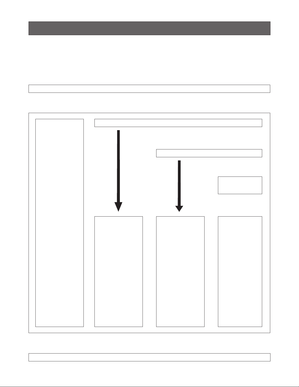
■ Basic Operating Flow
The operation starts with a log-in procedure. It proceeds to system unit selection, monitor selection and camera selection.
Alarm operations for the system such as alarm reset, suspension may be implemented. The operation ends with a log-out procedure.
OPERATING PROCEDURES (PS
•
Data)
LOG IN
SYSTEM UNIT SELECTION
MONITOR SELECTION
LOG OUT
SYSTEM
OPERATION
• Alarm Reset
• Alarm Suspend
• Alarm Suspend
Cancel
SYSTEM UNIT
OPERATION
• System Unit Setup
• System Function
• Alarm Recall
CAMERA
OPERATION
• Camera Setup
• Pan/Tilt (Slow)
• Iris/Focus/Zoom
• Preset Position
• Home Position
• Switching of
Color/Black &
White
• Auto Panning
• Camera Patrol
• Camera Patrol
Stop
• Camera Patrol
Learn
• Camera Function
• Wiper/Defroster
• Auxiliary Control
1/2
CAMERA
SELECTION
d
d
d
MONITOR
OPERATION
• Switching of VCR
and CAM
• Multiscreen
Selection
• Still
• Electronic Zoom
• Sequence
• Sequence Pause
23
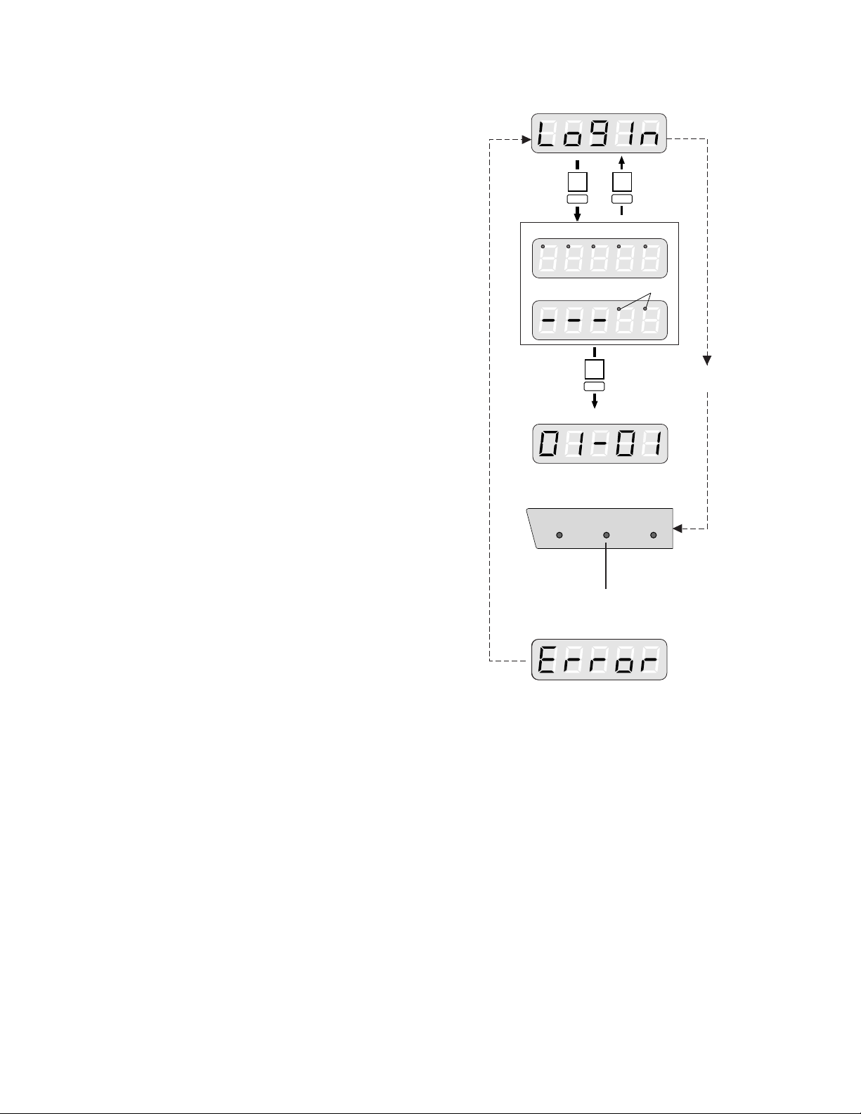
■ Login/Logout
● Log In
Right after powering up, the controller will be operable without password entry, provided user password certification is
set to Off in the setup menu.
When set to On, you will be prompted to enter your registered password. The default password is “12345”, but you
need to remember the password assigned to you by your
system administrator.
1. Insert the DC plug into the DC 9 V IN jack and connect
the AC adapter to an AC outlet.
2. The controller number, software versions and [LogIn]
appear in that order on the LED display.
The LOGIN indicator lights up. The controller is now
operable unless password certification is activated. If it
is not activated, proceed as follows.
3. Press the CAM/SET button.
4. Enter a 5-digit user password with the numeric buttons.
The initial factory setting is [12345].
5. Press the CAM/SET button.
6. If password entry for user authorization has been successful, the LOGIN indicator lights up.
The unit assigned to the UNIT A/UNIT button as number
1 is selected automatically.
If password entry has failed, [Error] appears on the display. The display returns to [LogIn].
● Log Out
1. Press the MON/ESC and CAM/SET buttons for about 2
seconds simultaneously.
2. [LogIn] appears on the display and the LOGIN indicator
goes off.
3. Disconnect the DC plug from the controller, and remove
the AC adapter from the AC outlet.
Note: If the power is not turned off after logout, the
alarm indicator and alarm suspend indicator will
display the same status as in normal operation.
SET
SET
ESC
Unauthorized
OPERATE LOGIN ALARM
SET
Ready for user password entry
Authorized
User password entry
Blink
The unit that is assigned to the UNIT A/UNIT
button as number 1 is selected automatically.
Lights after authorization
Goes off after logout
Certification
off

24
● Selecting with UNIT A/UNIT B Button
The unit numbers (01-99) of some frequently used units can
be assigned to numeric buttons 1-9 in the setup. Units can
be divided in two groups, one assigned to the UNIT A and
the other to the UNIT B button. A frequently used system
unit can be easily selected by pressing one numeric button
and then the UNIT A or UNIT B button.
1. Enter a single digit number (1-9).
Omit this step when you wish to select unit number “1”,
as this unit is selected by default.
2. Press the UNIT A or UNIT B button while the SHIFT
indicator is off.
The selected unit address appears in the unit section of
the LED display.
The selected camera number appears in the camera
section of the LED display.
■ System Unit Selection
Connected system units can be selected either by their unit
number (01-99) or by a single-digit number (1-9) assigned
to the UNIT A or UNIT B button.
● Selecting with Unit Number
1. Enter a unit number (01-99) with the numeric buttons.
2. Press the SHIFT button to turn the shift indicator on,
then press the UNIT A/UNIT button.
The selected unit number appears in the unit section of
the LED display.
The selected camera number appears in the camera
section of the LED display.
Notes:
• To confirm the selected unit number when the monitor number appears in the unit section of the LED
display, take procedure 2 or press MON/ESC button .
• If no unit is connected, [Err] appears a few seconds
after unit selection. In such a case, confirm the unit
address and repeat the above procedure.
• If the unit address of a system unit is unknown, consult your system administrator.
• When multiple system units such as Data Multiplex
Unit are connected to the System Controller and the
UNIT A or UNIT B button is pressed, the camera
number on the controller's LED display will not
agree with the camera picture on the monitor.
In this case, select the monitor and camera as
described on the next page.
MON
LOGOUT
ESC SET
CAM
UNIT A
then
SHIFT
UNIT
MON
ESC SET
CAM
LOGOUT
UNIT A
UNIT B
or
UNIT
 Loading...