

Page 1
ND400_Basic.book 1 ページ 2008年4月8日 火曜日 午後3時59分
Network Disk Recorder
Installation Guide
Model No. WJ-ND400
1
2
3
4
5
6
7
8
9
Before attempting to connect or operate this product,
please read these instructions carefully and save this manual for future use.
Page 2
ND400_Basic.book 2 ページ 2008年4月8日 火曜日 午後3時59分
We declare under our sole responsibility that the product to which this
declaration relates is in conformity with the standards or other normative
documents following the provisions of Directives 2006/95/EC and
Preface
2004/108/EC.
Wir erklären in alleiniger Verantwortung, daß das Produkt, auf das sich
diese Erklärung bezieht, mit der folgenden Normen oder normativen
Dokumenten übereinstimmt. Gemäß den Bestimmungen der Richtlinie
2006/95/EC und 2004/108/EC.
WARNING:
• This apparatus must be earthed.
• Apparatus shall be connected to a main socket outlet with a protective earthing connection.
• The mains plug or an appliance coupler shall remain readily
operable.
• To prevent fire or electric shock hazard, do not expose this
apparatus to rain or moisture.
• The apparatus should not be exposed to dripping or splashing
and that no objects filled with liquids, such as vases, should be
placed on the apparatus.
• All work related to the installation of this product should be made
by qualified service personnel or system installers.
• The connections should comply with local electrical code.
CAUTION:
Before attempting to connect or operate this product, please
read the label on the bottom.
CAUTION:
An ALL-POLE MAINS SWITCH with a contact separation of at
least 3 mm in each pole shall be incorporated in the electrical
installation of the building.
CAUTION
The lightning flash with arrowhead symbol,
within an equilateral triangle, is intended to
alert the user to the presence of uninsulated
"dangerous voltage" within the product's
enclosure that may be of sufficient magnitude to constitute a risk of electric shock to
persons.
The exclamation point within an equilateral
triangle is intended to alert the user to the
presence of important operating and maintenance (servicing) instructions in the literature accompanying the appliance.
Power disconnection. Unit with or without ON-OFF switches
have power supplied to the unit whenever the power cord is
inserted into the power source; however, the unit is operational
only when the ON-OFF switch is in the ON position. Unplug the
power cord to disconnect the main power for all units.
Nous déclarons sous note seule responsabilité que le produit auquel se
réfère la présente déclaration est conforme aux normes ou autres
documents normatifs conformément aux dispositions des directives
2006/95/CE et 2004/108/CE.
Nosotros declaramos bajo nuestra única responsabilidad que el
producto a que hace referencia esta declaración está conforme con las
normas u otros documentos normativos siguiendo las estipulaciones de
las directivas 2006/95/CE y 2004/108/CE.
Noi dichiariamo sotto nostra esclusiva responsabilità che il prodotto a
cui si riferisce la presente dichiarazione risulta conforme ai seguenti
standard o altri documenti normativi conformi alle disposizioni delle
direttive 2006/95/CE e 2004/108/CE.
Wij verklaren als enige aansprakelijke, dat het product waarop deze
verklaring betrekking heeft, voldoet aan de volgende normen of andere
normatieve documenten, overeenkomstig de bepalingen van Richtlijnen
2006/95/EC en 2004/108/EC.
Vi erklærer os eneansvarlige for, at dette produkt, som denne
deklaration omhandler, er i overensstemmelse med standarder eller
andre normative dokumenter i følge bestemmelserne i direktivene
2006/95/EC og 2004/108/EC.
Vi deklarerar härmed värt fulla ansvar för att den produkt till vilken
denna deklaration hänvisar är i överensstämmelse med
standarddokument, eller andra normativa dokument som framställs i
direktiv nr. 2006/95/EC och 2004/108/EC.
Ilmoitamme yksinomaisella vastuullamme, että tuote, jota tämä ilmoitus
koskee, noudattaa seuraavia standardeja tai muita ohjeellisia asiakirjoja,
jotka noudattavat direktiivien 2006/95/EC ja 2004/108/EC säädöksiä.
Vi erklærer oss alene ansvarlige for at produktet som denne erklæringen
gjelder for, er i overensstemmelse med følgende normer eller andre
normgivende dokumenter som følger bestemmelsene i direktivene
2006/95/EC og 2004/108/EC.
For U.K.
FOR YOUR SAFETY PLEASE READ THE FOLLOWING TEXT CAREFULLY.
This appliance is supplied with a moulded three pin mains plug for your
safety and convenience.
A 5 amp fuse is fitted in this plug.
Should the fuse need to be replaced please ensure that the replace-
ment fuse has a rating of 5 amp and that it is approved by ASTA or BSI
to BS1362.
Check for the ASTA mark
fuse.
If the plug contains a removable fuse cover you must ensure that it is
refitted when the fuse is replaced.
If you lose the fuse cover the plug must not be used until a replacement
cover is obtained.
A replacement fuse cover can be purchased from your local Panasonic
Dealer.
IF THE FITTED MOULDED PLUG IS UNSUITABLE FOR THE SOCKET OUTLET IN YOUR HOME THEN THE FUSE SHOULD BE
REMOVED AND THE PLUG CUT OFF AND DISPOSED OF SAFELY.
THERE IS A DANGER OF SEVERE ELECTRICAL SHOCK IF THE
CUT OFF PLUG IS INSERTED INTO ANY 13 AMP SOCKET.
If a new plug is to be fitted please observe the wiring code as shown
below.
If in any doubt please consult a qualified electrician.
WARNING: This apparatus must be earthed.
The wires in this mains lead are coloured in accordance with the following code.
As the colours of the wire in the mains lead of this appliance may
not correspond with the coloured markings identifying the terminals in
your plug, proceed as follows.
The wire which is coloured green-and-yellow must be connected to
the terminal in the plug which is marked with the letter E or by the earth
symbol
The wire which is coloured blue must be connected to the terminal
in the plug which is marked with the letter N or coloured black.
The wire which is coloured brown must be connected to the terminal in the plug which is marked with the letter L or coloured red.
How to replace the fuse
Open the fuse compartment with
a screwdriver and replace the fuse
and fuse cover.
Green-and-yellow: Earth
Blue: Neutral
Brown: Live
or coloured green or green-and-yellow.
or the BSI mark on the body of the
IMPORTANT
FUSE
2
Page 3
ND400_Basic.book 3 ページ 2008年4月8日 火曜日 午後3時59分
For U.S.A.
The model number and serial number of this product may be
found in the unit. You should note the model number and
serial number of this unit in the space provided and retain this
book as a permanent record of your purchase to aid identification in the event of theft.
Model No.
Serial No.
For Canada
This Class A digital apparatus complies with Canadian ICES-
003.
For U.S.A.
NOTE: This equipment has been tested and found to comply
with the limits for a Class A digital device, pursuant to Part 15
of the FCC Rules. These limits are designed to provide
reasonable protection against harmful interference when the
equipment is operated in a commercial environment.
This equipment generates, uses, and can radiate radio
frequency energy and, if not installed and used in accordance
with the instruction manual, may cause harmful interference
to radio communications.
Operation of this equipment in a residential area is likely to
cause harmful interference in which case the user will be
required to correct the interference at his own expense.
FCC Caution: To ass
use only shielded interface cables when connecting to
computer or peripheral devices). Any changes or modifica-
tions not expressly approved by the party responsible for
compliance could void the user's authority to operate this
equipment.
ure continued compliance, (example -
3
Page 4
ND400_Basic.book 4 ページ 2008年4月8日 火曜日 午後3時59分
4
Page 5

ND400_Basic.book 5 ページ 2008年4月8日 火曜日 午後3時59分
Contents
Preface
Preface.............................................................................................................................................................. 7
About these Operating Instructions................................................................................................................... 7
System Requirements for a PC ........................................................................................................................ 8
Trademarks and Registered Trademarks ......................................................................................................... 8
Network Security............................................................................................................................................... 8
Precautions ....................................................................................................................................................... 9
Major Operating Controls and Their Functions .................................................................11
Front View....................................................................................................................................................... 11
Inside the Front Cover .................................................................................................................................... 13
Rear View ....................................................................................................................................................... 15
Using the Brace ......................................................................................................................................... 15
Description of Functions
Outline of Functions .............................................................................................................16
HDD ................................................................................................................................................................ 16
Mega Pixel Camera Compatibility and Capacity........................................................................................ 16
Replace HDDs ........................................................................................................................................... 16
HDD Space Management.......................................................................................................................... 16
HDD Fault Tolerance System .................................................................................................................... 17
Encrypting Data Recorded on the HDDs ................................................................................................... 17
Recording and Playing Images ....................................................................................................................... 18
Stable recording and playback of images .................................................................................................. 18
Setting Schedules ...................................................................................................................................... 18
Event Functions ......................................................................................................................................... 18
List of Functions......................................................................................................................................... 19
Setup Menu List ......................................................................................................................................... 19
Network........................................................................................................................................................... 20
Remote Operation ..................................................................................................................................... 20
Network Security Function ......................................................................................................................... 20
SD Memory Recording............................................................................................................................... 21
Maintenance (Version Upgrade)................................................................................................................ 21
Installation and Setup
Getting Started ......................................................................................................................22
Setup Procedure ............................................................................................................................................. 22
Setting up the Rack ..............................................................................................................23
Rack Mounting ................................................................................................................................................ 23
Rack mounting positions ................................................................................................................................. 24
Connections ..........................................................................................................................25
Connecting the PC and the Camera ............................................................................................................... 25
1 Port Operation ........................................................................................................................................ 25
2 Port Operation ........................................................................................................................................ 26
Example of Connectivity with 1 Port Operation.......................................................................................... 27
Example of Connectivity with 2 Port Operation.......................................................................................... 29
Connecting the Extension Unit........................................................................................................................ 31
5
Page 6

ND400_Basic.book 6 ページ 2008年4月8日 火曜日 午後3時59分
Contents
About Connectors.................................................................................................................32
Using the Alarm/Control connector ................................................................................................................. 32
Pin Assignments ........................................................................................................................................ 32
Connectivity for Emergency Recording...................................................................................................... 33
Connectivity for Switching to External Recording ...................................................................................... 33
Auto Adjustment Time Function Connection 1........................................................................................... 33
Auto Adjustment Time Function Connection 2........................................................................................... 34
Connectivity for Control Output .................................................................................................................. 34
Uninterruptible Power Supply (UPS) Connectivity..................................................................................... 35
Using the Alarm Connector ............................................................................................................................. 36
Pin Assignments ........................................................................................................................................ 36
Alarm Connectivity ..................................................................................................................................... 37
Alarm/Control connector and Alarm Connector Timing and Polarity .............................................................. 38
Power Supply ........................................................................................................................39
Turning On the Power ..................................................................................................................................... 39
Turning Off the Power..................................................................................................................................... 39
During Recording ....................................................................................................................................... 39
During Playback......................................................................................................................................... 39
Using the Front Panel for Operations .................................................................................40
Basic Operations............................................................................................................................................. 40
Checking System Information ......................................................................................................................... 41
Checking the IP Address ................................................................................................................................ 42
Setting the IP Address .................................................................................................................................... 43
Configuring the Settings for Each Item ...................................................................................................... 43
Setting and Canceling Key Lock ..................................................................................................................... 43
HDD Unit......................................................................................................................................................... 44
Handling the HDD ........................................................................................................................................... 45
Installing HDDs .......................................................................................................................................... 46
Installing HDDs by unit............................................................................................................................... 47
Removing HDDs ........................................................................................................................................ 48
Removing HDDs by unit............................................................................................................................. 50
Setting the HDD's Operation Mode............................................................................................................ 51
HDD Error Recovery (During RAID Operation)............................................................................................... 52
Replacing Faulty HDD during RAID Operation .......................................................................................... 53
Rebooting........................................................................................................................................................ 54
Attachments
Troubleshooting....................................................................................................................55
Problems......................................................................................................................................................... 55
Specifications........................................................................................................................57
WJ-ND400 ...................................................................................................................................................... 57
Accessories...........................................................................................................................58
Standard Accessories ..................................................................................................................................... 58
Index.......................................................................................................................................59
6
Page 7

ND400_Basic.book 7 ページ 2008年4月8日 火曜日 午後3時59分
Preface
The Network Disk Recorder (WJ-ND400) is for recording images and audio from network surveillance cameras to a hard disk (hereafter HDD). It
is possible to connect up to 64 cameras over a network.
Also, it is possible to access and operate the recorder via a network from the web browser on a computer (hereafter PC). A maximum of 16 PCs
can be connected (via a network).
• The network settings for the PC need to be done to do settings and operations from the PC. A web browser must also be installed.
About these Operating Instructions
There are four manuals, they include the Installation Guide, Setup Instructions (PDF file), Operating Instructions (PDF file), and the Quick
Reference Guide.
• Installation Guide : How to configure required settings and connect the equipment.
• Setup Instructions (PDF file) : How to configure required settings and connect the equipment to perform operations
from a PC over a network.
• Operating Instructions (PDF file) : How to perform operations from a PC.
• Quick Reference Guide : Basic settings and frequently used functions.
®
Reader is required to read the “Operating Instructions” and the “Setup Instructions” on the provided CD-ROM. When the Adobe® Reader
Adobe
is not installed on the PC, download the latest Adobe
®
Reader from the Adobe web site and install it.
In this manual and on the screen, the ND400 and the recorder are shown as WJ-ND400.
Refer to the "readme.txt" file on the CD-ROM bundled with the recorder for information about the versions and types of separately available
software and cameras supported.
The following abbreviations are used in this document.
Microsoft
Microsoft
®
Windows Vista® Business (32-bit) is called Windows Vista®.
®
Windows® XP Professional SP2, and Microsoft® Windows® XP Home Edition SP2 are called Windows® XP.
7
Page 8

ND400_Basic.book 8 ページ 2008年4月8日 火曜日 午後3時59分
System Requirements for a PC
It is recommended to operate this unit using a PC that meets the following system requirements.
• OS : Microsoft® Windows Vista® Business (32-bit)
®
:Microsoft
Windows ® XP Professional SP2
:Microsoft® Windows ® XP Home Edition SP2
• OS Language : English, French, Spanish, German, Italian, Russian, Chinese
®
• CPU : Pentium
4 3.0 GHz or faster
• Memory : 1 GB or more (512 MB or more is required when using Microsoft
• Monitor : Resolution: 1 024 x 768 pixels or more
Color: 24-bit True color or better
•Network interface : 10/100/1 000 Mbps Ethernet port x1
®
• Web Browser : Windows
:Microsoft
Internet Explorer® 7.0
®
Internet Explorer® 6.0 SP2
• Audio interface : Sound card (when using the audio function)
• Other : CD-ROM drive: It is necessary to read the operating instructions and use the software on the provided
CD-ROM.
®
9.0c or later
®
Reader®: It is necessary to read the operating instructions on the provided CD-ROM.
*Microsoft
:DirectX
:Adobe
®
Internet Explorer® 6.0 SP2 is required when using Microsoft® Windows® XP Professional SP2 or Microsoft® Windows® XP Home
Edition SP2.
*
*
®
Windows® XP.)
*
Important:
• When using a PC that does not meet the above requirements, displaying of images may become slow or the web browser may become
inoperable.
• Audio may not be heard if a sound card is not installed on a PC. Audio may be interrupted depending on the network environment.
®
• Refer to "Notes on Vista
" (PDF) for further information about system requirements for a PC and precautions when using Microsoft
Windows Vista®.
Trademarks and Registered Trademarks
•Adobe Reader is a trademark or registered trademark of Adobe Systems Incorporated in the USA and other countries.
• Microsoft, Windows, Windows Vista, Internet Explorer, ActiveX and Direct X are trademarks or registered trademarks of Microsoft Corporation
in the USA and other countries.
• Intel and Pentium are trademarks or registered trademarks of Intel Corporation and its subsidiaries in the USA and other countries.
• RSA is a registered trademark of RSA Security Inc. BSAFE is a registered trademark of RSA Security in the USA and other countries.
• Other names of companies and products contained in these operating instructions may be trademarks or registered trademarks of their
respective owners.
Network Security
As you will use this product connected to a network, your attention is called to the following security risks.
1. Leakage or theft of information through this product
2. Use of this product for illegal operations by persons with malicious intent
3. Interference with or stoppage of this product by persons with malicious intent
It is your responsibility to take precautions such as those described below to protect yourself against the above network security risks.
• Use this product in a network secured by a firewall, etc.
• If this product is connected to a network that includes PCs, make sure that the system is not infected by computer viruses or other malicious
entities (using a regularly updated anti-virus program, anti-spyware program, etc.).
• Protect your network against unauthorized access by restricting users to those who log in with an authorized user name and password.
• Apply measures such as user authentication to protect your network against leakage or theft of information, including image data,
authentication information (user names and pass
words), alarm mail information, FTP server information and DDNS server information.
®
8
Page 9

ND400_Basic.book 9 ページ 2008年4月8日 火曜日 午後3時59分
Precautions
z Refer all work related to the installation of this product to
qualified service personnel or system installers.
z Do not operate the unit beyond their its specified
temperature, humidity, or power source ratings.
Use the unit at temperatures between +5 ºC - +45 ºC {41 ºF - 113
ºF} and where the humidity is between 5 % - 90 %.
The input power source for NTSC model is 120 V AC 60 Hz, for
PAL model is 220 V - 240 V AC 50 Hz.
Performance and lifetime of hard disk drives are easily affected
by heat (used at high temperature) characteristically. It is
recommended to use this unit at temperatures between +20 ºC +30 ºC {68 ºF - 86 ºF}.
z POWER switch
The POWER switch is located on the rear of the unit. Even
though the POWER switch is set to "OFF", the power supply will
not be cut. To cut the power supply, unplug the power plug of the
unit from the AC outlet. When using the power supply control
unit, turn off the power of the power supply control unit.
z Built-in backup battery
Before the first use, charge the built-in backup battery (lithium
battery) by turning on the power for 48 hours or more.
If it is not charged enough, in a case where the power goes
down, the internal clock may keep bad time or the operative
condition may be different to that before the electric power
failure.
The built-in battery life is approximately 5 years as an indication
of replacement. (This is just an indication of replacement. We are
not providing any guarantee of the built-in battery lifetime.
Replacement cost of the built-in battery is not covered by the
warranty even if it needs to be done within the warranty period.)
Ask the dealer where you purchased the unit when replacement
of the battery is required.
z Hard disk drives
Hard disk drives are vulnerable to vibration. Handle them with
care.
It is possible to damage them if they are moved while their
motors are still running. Do not move them just after turning their
power on or off (for around 30 seconds).
⋅ A lifetime of hard disk drives is limited by use.
It is recommended to replace them after around 18 000 hours
of operation to prevent data loss from disk failures.
Write error may occur frequently after around 20 000 hours of
operation and the head and motor deterioration may occur
and will reach their lifetime after 30 000 hours of operation
when they have been used at the recommended ambient
temperature (approx. +25 ºC {77 ºF}).
When hard disk drive trouble occurs, replace it immediately.
Consult your dealer for servicing.
⋅ Hard disk drives are precise devices. Do not leave them
where the temperature is high and humid.
⋅ Do not touch the connector of the removable hard disk by
hand directly to protect the hard disk drive from static
electricity.
⋅ Take notice of the following for the removed hard disks.
⋅ Do not leave them where the temperature is high and
humid. It may cause condensation.
⋅ Place them where the temperature is between 0 ºC {32 ºF}
and 30 ºC {86 ºF} and humidity is between 20 - 40 % when
they are not used for a long time (six months or more).
Consult your dealer for further information.
⋅ Operate them for around an hour at least once every six
months when they are not used for a long time.
⋅ When placing them stacked, do not stack more than four
disks.
z Heat dissipation
Refer to the following to prevent fire and malfunction of the unit.
⋅ Do not block the ventilation openings in the cover to prevent
the unit from overheating. Maintain the unit periodically to
prevent dust from blocking openings.
⋅ Clear a space of more than 5 cm {1.97 "} from both sides, the
top, and the rear of the unit.
⋅ A lifetime of the cooling fan is limited by use.
z Grounding
Confirm that the wire is connected from the SIGNALGND
terminal to earth ground.
A grounding connection must be made before connecting the
power plug of the unit to the main power supply.
When disconnecting the grounding wire, make sure that the
power plug of the unit is disconnected from the main power
supply.
z Avoid placin
If the unit is placed near noise sources such as fluorescent
lamps, noises may be produced. In this case, rewire avoiding the
noise sources, or move the unit to the place far from them.
z Places to avoid
Do not place the unit in the following places:
⋅ Places exposed to direct sunlight
⋅ Places subject to having strong vibration or impact
⋅ Near magnetic field sources such as a television or speakers
⋅ Place where condensation forms easily, where temperature
changes greatly, humid places
⋅ Steamy and oily places such as kitchens
⋅ Places which are not level
g the unit near noise sources
z Cleaning
Turn the power off when cleaning the unit. Otherwise it may
cause injuries.
Do not use strong or abrasive detergents when cleaning the unit
body.
Use a dry cloth to clean the unit when it is dirty.
When the dirt is hard to remove, use a mild detergent and wipe
gently.
9
Page 10

ND400_Basic.book 10 ページ 2008年4月8日 火曜日 午後3時59分
z Indication label
Refer to the indication label placed on the surface of the unit as to
the indications of equipment classification and power source, etc.
z Handle the unit with care.
Do not strike or shake, as this may damage the unit.
z Do not strike or give a strong shock to the unit.
It may cause damage or allow water to enter the unit.
z Place the unit horizontally on a level surface.
Do not place the unit in an upright position. When stacking
multiple units, clear a space of more than 5 cm {1.97 "} from both
sides, the top, the bottom and the rear of the units.
z Avoid placing receptacles that contain liquids such as water
near the unit.
If liquid spills onto the unit, it may cause fire or an electric shock.
z Prevent condensation from forming on the surface of the
hard disk.
If this happens, do not turn on the power of the recorder and
leave the recorder for around 2 hours.
Wait until the dew evaporates in any of the following cases:
⋅ The recorder is placed in an extremely humid place.
⋅ The recorder is placed in a room where a heater has just
been turned on.
⋅ The recorder is moved from an air-conditioned room to a
humid and high-temperature room.
⋅ When the unit has not been used for a certain period, turn on
the power of the unit (approximately once a week), and
perform recording/playback to prevent interferences with
functions.
⋅ We recommend that you make a note of your settings and
save them. This will help when you are required to change
the system configuration, or when unexpected trou
failure occurs.
⋅ Distributing, copying, disassembling, reverse compiling,
reverse engineering, and also exporting in violation of export
laws of the software provided with this product, is expressly
prohibited.
ble or
z MPEG-4 Visual patent portfolio license
This product is licensed under the MPEG-4 Visual patent portfolio
license for the personal and non-commercial use of a consumer
for (i) encoding video in compliance with the MPEG-4 Visual
Standard ("MPEG-4 Video") and/or (ii) decoding MPEG-4 Video
that was encoded by a consumer engaged in a personal and
non-commercial activity and/or was obtained from a video
provider licensed by MPEG LA to provide MPEG-4 Video. No
license is granted or shall be implied for any other use. Additional
information including that relating to promotional, internal and
commercial uses and licensing may be obtained from MPEG LA,
LLC. See http://www.mpegla.com.
z GPL/LGPL
⋅ This product includes software based on GNU General
Public License (GPL) and a Lesser General Public License
(LGPL).
⋅ Customers can duplicate, distribute, and modify the source
code of the relevant software according to the GPL and
LGPL.
⋅ For detailed information about the relevant software, refer to
the "readme.txt" file in the "GPL/LGPL" folder on the CDROM included with the main unit.
⋅ Please note that Panasonic cannot respond to questions
regarding the source code.
10
Page 11
ND400_Basic.book 11 ページ 2008年4月8日 火曜日 午後3時59分
Major Operating Controls and Their Functions
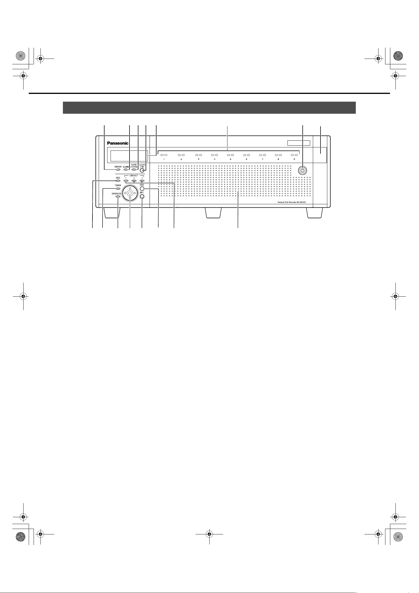
Front View
(1) Error indicator [ERROR]
Blinks when errors or problems with the recorder's operation
occur.
Blinks red : System errors
Blinks orange : Temperature is too high or low.
Cooling fan stopped, etc.
(2) Alarm indicator [ALARM]
Blinks : Alarm has occurred
Lights : Alarm output stopped
Off : Alarm is resolved or no alarm has
occurred
Refer to the Operating Instructions (PDF file) for more
information about alarms.
(3) Alarm suspension indicator
[ALARM SUSPEND]
Lights : Alarm suspend stopped
Off : Alarm is not suspended
Refer to the Operating Instructions (PDF file) for more
information about alarm suspension.
(4) Buzzer stop button [BUZZER STOP]
Use to turn off the buzzer after an alarm or error occurs.
Refer to the Operating Instructions (PDF file) for more
information about alarms and errors.
(5) LCD
Displays the recorder's status (errors etc.) and functions that
are operated using the buttons on the front panel.
(6)(5)(3)(2) (7)(1) (4)
(8)
(16)(15)(9) (10) (11) (12) (13) (14)
(6) HDD indicators ("HDD1" to "HDD9")
HDD access indicator (right side)
Indicates the access status and problems of the HDD.
When errors occur on an HDD in RAID5/RAID6 mode,
the indicator lights or blinks red.
Blinks green : Accessing HDD
Off : Not accessing HDD
Lights red : Errors have occurred on the internal
HDD
(Data can be recovered by replacing
HDD.)
• When in RAID5 mode, the first HDD
has errors
• When using RAID6, the first two
HDDs have errors.
Blinks red : Errors have occurred on the internal
Lights orange and
red
(Alternately)
The indicators display the status of the drives from HDD1 to
HDD9, but if a system errors occur, each indicator has the
same display.
HDD
(Data cannot be recovered even if
HDD is replaced)
• When in RAID5 mode, the second
HDD has errors
• When in RAID6 mode, the third HDD
has errors
: Recovering data from drive in RAID5/
RAID6 mode.
(This indicator looks orange during
high-speed processing.)
11
Page 12

ND400_Basic.book 12 ページ 2008年4月8日 火曜日 午後3時59分
Major Operating Controls and Their Functions
Important:
• When the HDD indicators light red in the RAID5/RAID6 mode,
quickly replace the HDD where the errors occurred. Contact
your dealer for information on replacing HDDs.
⋅ RAID5 mode:
Data cannot be recovered when two or more HDD
indicators are lighting or blinking red.
⋅ RAID6 mode:
Data cannot be recovered when three or more HDD
indicators are lighting or blinking red.
HDD status indicator (left side)
Shows the operating status of the HDDs.
Lights green : HDD power [On]
(HDD formatted)
Blinks green : HDD for playback only
(only for playback, recording not
possible)
Blinks orange : Formatting HDD
Lights red : HDD format failed
Off : HDD power [Off]
HDD is not connected or not
recognized
(14) Escape button [ESC]
Use to return to the previous screen when doing operations
on the LCD.
(15) Link indicators [LINK/ACT]
Camera Link indicator [LINK/ACT1]
Lights or blinks when linked with camera.
Lights green : When a camera port connection is
established
Blinks green : Receiving data
PC Link indicator [LINK/ACT2]
Lights or blinks when connected to a PC (PC and camera
when one port used).
Lights green : When a client PC port connection is
established
Blinks green : Receiving data
Reserved Link indicator [LINK/ACT3]
This indicator is for future extension (off).
(16) Front cover
Open to add, or replace HDD units and to configure HDD
operations (Single/RAID5/RAID6).
Keep it closed and locked during normal operations.
(7) Key hole
Use to open and close the front cover.
Keep the key in a safe place.
Lock : Turn key to left
Open : Turn key to right
(8) Maintenance port
Use for service when connected directly to a PC. Normally, it
is not used.
Note:
• Use a straight cable to connect a PC directly to the
maintenance port.
(9) Recording indicator [REC]
Lights : Recording
Off : Recording finished.
(10) Timer indicator [TIMER]
Lights : When a schedule is set
Blinks : Schedule recording in-progress
(11) Operate indicator [OPERATE]
Lights : Power [On]
Off : Power [Off]
(12) Arrow buttons (up, down, left, or right)
Use to move the cursor on the LCD and for direct input of
values.
(13) Set button [SET]
Use to set items on the LCD.
12
Page 13
ND400_Basic.book 13 ページ 2008年4月8日 火曜日 午後3時59分
Major Operating Controls and Their Functions
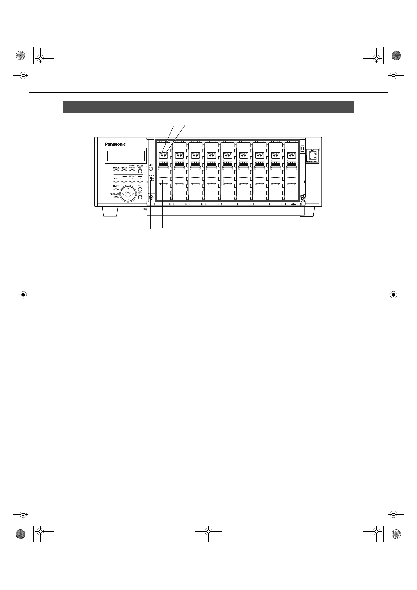
Inside the Front Cover
(1)
(2)
(3) (4)
(5)
(6) (7)
(1) USE button [USE]
Used when adding or replacing an HDD or changing the
operating mode of the HDD.
Installing or
removing an HDD
HDD operation
mode
Change
: You can install or remove the HDD by
holding down the button for at least 2
seconds, waiting for the buzzer to
sound, and using the front panel
buttons and LCD operations.
: The settings become effective after
setting the [RAID] switch and turning
on the Power switch while holding
down the [USE] button to boot up.
Remember to hold down the [USE]
button until the buzzer sounds.
(2) HDD unit
HDD in special canister.
Add and replace HDDs by using the LCD on the front panel.
Refer to page 45 for details. Contact your dealer for
information on purchasing and replacing HDDs.
(3) HDD status indicator [STS]
Shows the operating status of the HDDs.
Lights green : HDD power [On]
(Formatted)
Blinks green : HDD for playback only
Blinks orange : Formatting HDD
Lights red : HDD format failed
Off : HDD power [Off]
(only for playback, recording not
possible)
HDD is not connected or not
recognized.
(4) HDD access indicator [A/F]
Indicates the access status and problems with the HDD.
When errors occur on an HDD in RAID5/RAID6 mode, the
indicator lights or blinks red.
Blinks green : Accessing HDD
Off : Not accessing HDD
Lights red : Errors have occurred on HDD
(Data can be recovered by replacing
HDD)
• When in RAID5 mode, the first HDD
has errors
• When using RAID6, the first two
HDDs have errors.
Blinks red : Errors have occurred on HDD
(Data cannot be recovered even if
HDD is replaced)
• When in RAID5 mode, the second
HDD has errors
• When in RAID6 mode, the third HDD
has errors
Alternating colors
(Orange/red)
: Recovering data from drive in RAID5/
RAID6 mode.
(This indicator looks orange during
high-speed processing.)
13
Page 14

ND400_Basic.book 14 ページ 2008年4月8日 火曜日 午後3時59分
Major Operating Controls and Their Functions
(5) HDD bay slots
Up to 9 HDD can be installed (one HDD unit is installed at the
factory).
Note:
• Limiting factors for the RAID5/RAID6 mode.
RAID5 mode : The RAID5 mode can be used when
more than three HDDs are installed.
RAID6 mode : The RAID6 mode can be used when
(6) RAID mode switch [RAID]
Switches the HDD operational mode (Single, RAID5, or
RAID6).
The settings become effective after setting the HDD
operation mode with the [RAID] switch and turning on the
power while holding down the [USE] button to boot up.
S : SINGLE mode (default)
R5 : RAID5 mode
R6 : RAID6 mode
more than four HDDs are installed.
Important:
• The HDD operation mode cannot be changed once the
system is operating. Recorded data may not be read correctly
when the mode is changed after the system is operating.
(7) Removal knob
Used when replacing the HDD units.
14
Page 15
ND400_Basic.book 15 ページ 2008年4月8日 火曜日 午後3時59分
Major Operating Controls and Their Functions
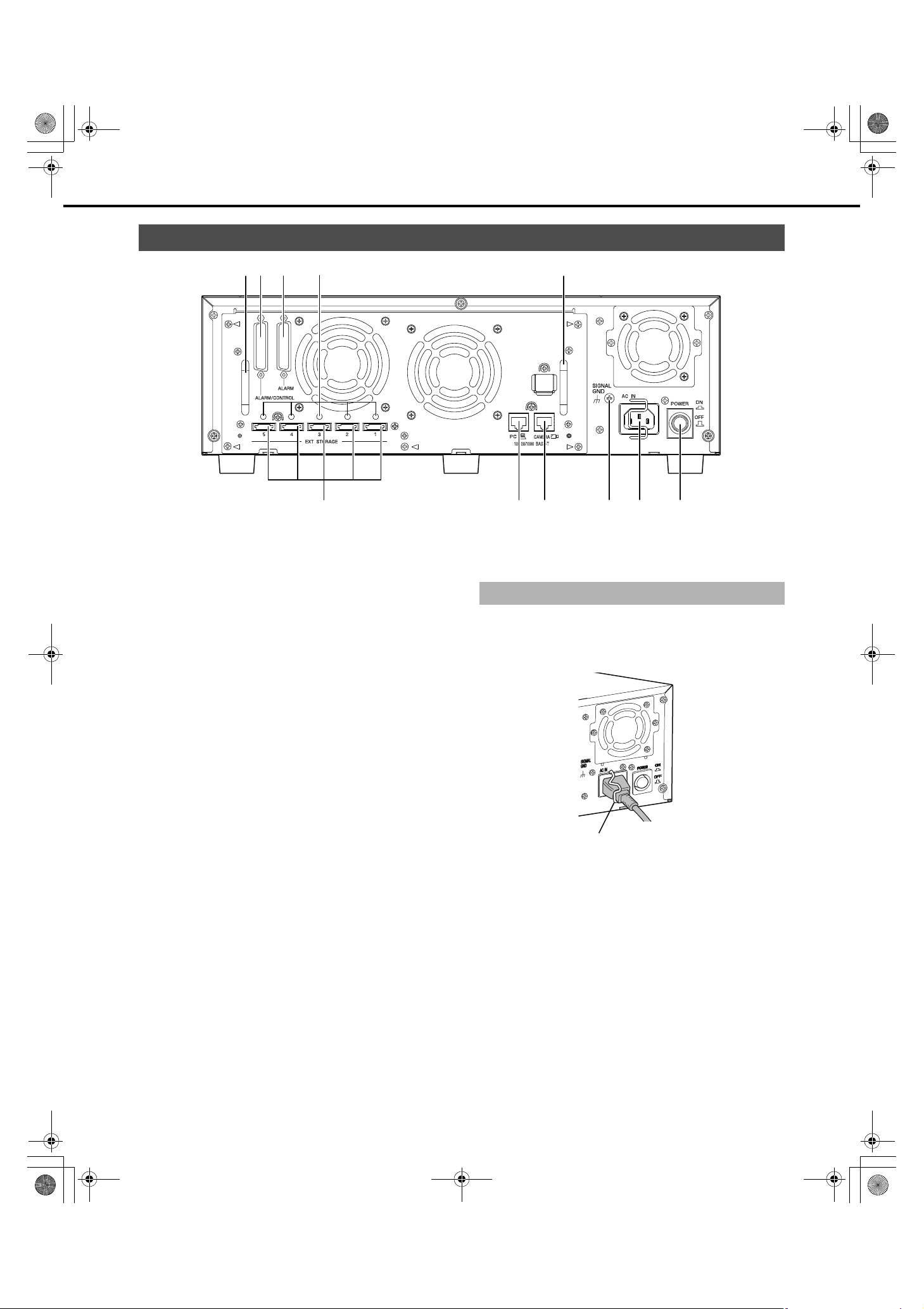
Rear View
(1)(2) (3) (1)
(4)
(1) Handle for Maintenance
Loosen the 5 screws indicated by the triangles and grip these
handles to pull off the panel when replacing the fan or doing
other maintenance work.
(2) Alarm/Control connector [ALARM/
CONTROL], D-Sub 25 pin
Use to connect alarm devices (buzzers or indicators),
external devices, control switches controlled by the recorder.
(3) Alarm connector [ALARM], D-sub 25 pin
Use to connect alarm-related devices such as a sensor or a
door switch.
(9) (10)(8)(7)(6)(5)
(10) Power switch [POWER]
Turns the power on. Press it again to turn the power off and
end operations.
Using the Brace
Secure the power cord with the brace.
1 Lock the power cord in place by lifting and latching the
brace.
(4) Cable clamp fixing holes
Install the cable clamp (provided with the extension unit) to
secure the connection cables.
For details refer to the manual for the extension unit (WJ-
HDE400).
(5) External storage connector [EXT STORAGE]
Use to connect the (WJ-HDE400) extension unit and the
recorder with the connection cable (provided with the
extension unit).
(6) Client PC port [PC]
Use to connect a PC, 10BASE-T, 100BASE-TX, or
1000BASE-T network.
(7) Camera port [CAMERA]
Use to connect a camera, 10BASE-T, 100BASE-TX, or
1000BASE-T network.
(8) Signal GND terminal [SIGNAL GND]
Use as a ground when the recorder's Signal GND terminal is
connected to another device's Signal GND terminal. Static or
other noise related problems may occur if a ground is not
connected.
(9) Power cord Inlet [AC IN]
Connect the provided power cord here. The power plug is a
two prong plug with a ground terminal.
Brace
15
Page 16
ND400_Basic.book 16 ページ 2008年4月8日 火曜日 午後3時59分
Description of Functions
Outline of Functions
HDD
Mega Pixel Camera Compatibility and
Capacity
The recorder can record high-definition images (mega pixel camera
images) in SXGA (1280 x 960) JPEG four times that of the existing
VGA (640 x 480). This makes it possible to record a wide angle of
view and to zoom in without fuzziness to check things.
Display on 21 in PC monitor
SXGA (1280 x 960) pixels
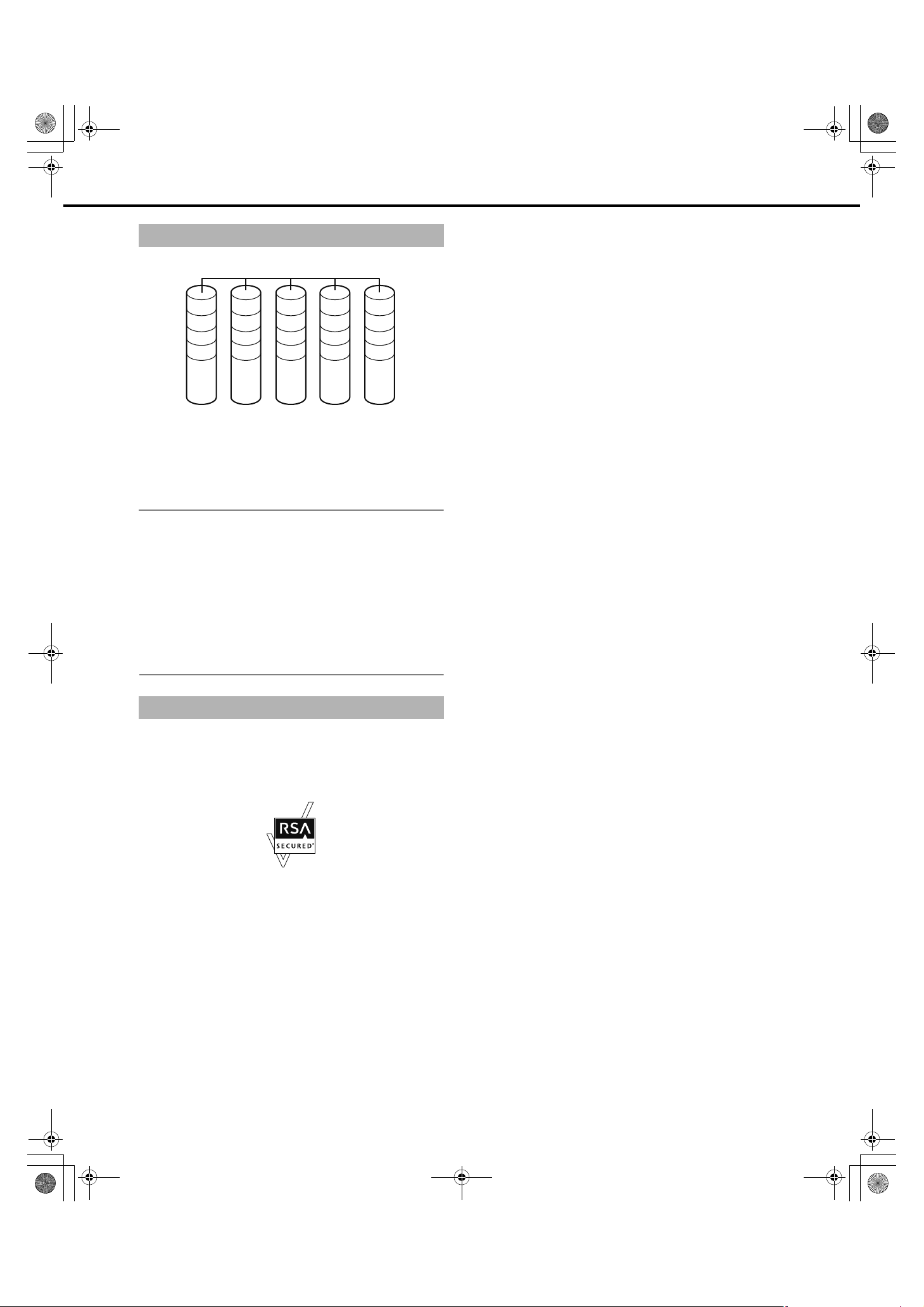
You can install up to 9 HDDs to record high-quality images for long
periods of time. Plus, you can add up to 5 extension units.
Conventional VGA
(640 x 480) pixels
Replace HDDs
Replacement is Easy
You can install and remove HDDs by opening the front panel.
If more than two HDDs are installed, replacement can be done
without stopping recording. Instructions are shown on the LCD to
reduce misoperations, and make maintaining and replacing HDDs
easy.
Use the special HDD canister provided to install the HDD.
The HDD unit is an HDD that is in the special canister. The HDD
units can be easily installed or removed from the HDD bay slots
inside the front cover.
* Contact your dealer for information on purchasing and replacing
HDDs.
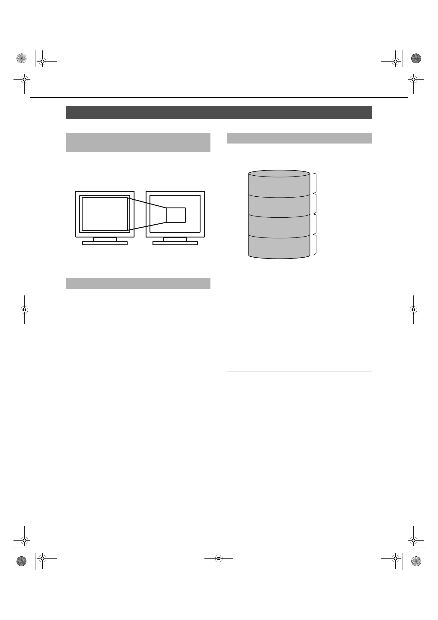
HDD Space Management
The HDDs in the recorder are virtually divided in the 4 image areas
shown below (refer to the Setup Instructions (PDF file)).
You can set only one area for each HDD.
Normal Recording Area
Event Recording Area
Pre-event Recording
Area
Copy Area
Yo u can check the remaining capacity
for each area on the Setup menu.
(1) Normal Recording Area
Area for recording except events.
Manual recording/schedule recording/SD memory data
(2) Event Recording Area
Area for recording when events occur.
Post-event recording/emergency recording
(3) Pre-event Recording Area
Area for pre-event recording.
(4) Copy area
Area where copied data is saved.
Note:
• The HDD provided in the recorder at the factory is initialized as
normal recording area. Unformatted HDDs inserted into the
recorder are automatically initialized as normal recording area.
• Recording/playback is not possible if only the Pre-event
Recording Area and the Copy Area are created. Create either
one normal recording area or event recording area.
• If a normal recording area is not created, manual and schedule
recordings are recorded to the event recording area. Also, if an
event recording area is not created, event and emergency
recordings are recorded to the normal recording area.
(1)
(2)
(3)
(4)
16
Page 17
ND400_Basic.book 17 ページ 2008年4月8日 火曜日 午後3時59分
HDD Fault Tolerance System
RAID 6
Outline of Functions
A 1
A 2
A 3
P 4
The RAID function makes it possible to improve the HDD's tolerance
to errors.
This product is equipped with the RAID6 mode that can recover
image data when two HDDs fail, in addition to the RAID5 mode that
can recover image data (RAID6 has two sets of error correcting
code data). This prevents loss of recorded image data on large
volume HDDs (refer to the Setup Instructions (PDF file).
B 1
B 2
P 3
Q 4
C 1
P 2
Q 3
A 4
P 1
Q 2
B 3
B 4
Q 1
C 2
C 3
C 4
Note:
• To use the RAID5 mode you need to connect 3 or more HDDs,
the RAID6 mode requires 4 or more HDDs.
• Theoretical volume when RAID5 mode enabled
Theoretical volume = HDD with smallest capacity in the unit x
(number of HDDs in the unit −1)
• Theoretical volume when RAID6 mode enabled
Theoretical volume = HDD with smallest capacity in the unit x
(number of HDDs in the unit −2)
• The capacity of the HDDs that are installed may be a few
percents smaller.
Encrypting Data Recorded on the HDDs
The image and audio data recorded on the HDDs is encrypted. The
image and audio data on the HDDs cannot be played except on the
recorder.
®
The recorder uses RSA
BSAFE™ software from RSA Security Inc.
17
Page 18
ND400_Basic.book 18 ページ 2008年4月8日 火曜日 午後3時59分
Outline of Functions
Recording and Playing Images
Stable recording and playback of images
High through put is achieved by separating the camera port and the
client PC port. In addition to acquiring extremely stable images, you
can connect a maximum of 64 cameras and 16 client PCs,
depending on your network.
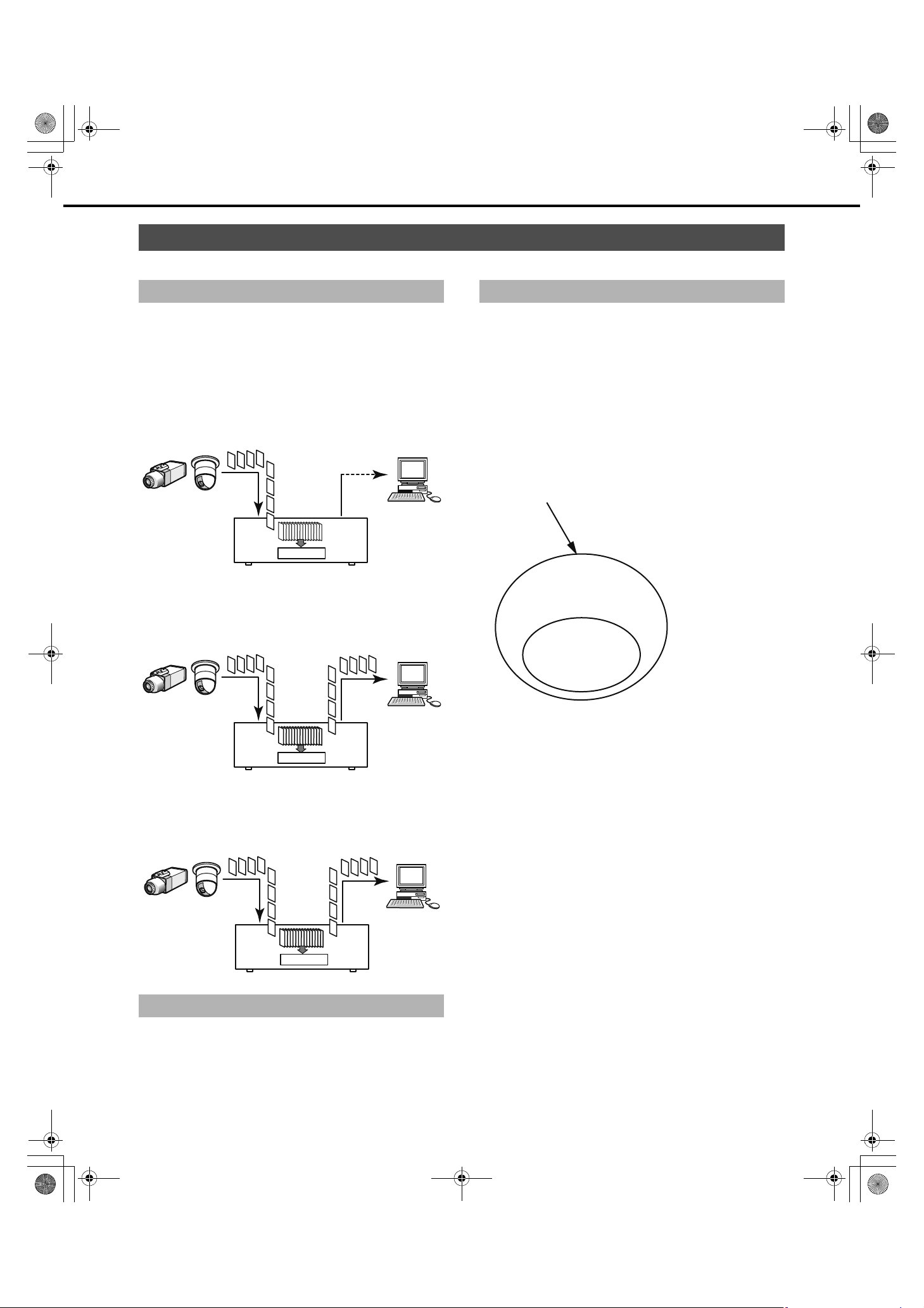
Recording
Camera images from network cameras are recorded on the
recorder. One Network Disk Recorder can record images from a
maximum of 64 cameras. JPEG, M-JPEG, and MPEG-4 images are
supported.
Image data
Network camera
HDD
Recorder
Playback
Images recorded on the HDD of the recorder are sent to and
displayed on a PC. One Network Disk Recorder can send images to
a maximum of 16 PCs.
Image data
PC
Event Functions
About Events
Events are things that trigger special operations by the recorder.
The event function includes terminal alarms, site alarms, and
command alarms.
For example, if a camera sends a site alarm, the recorder receives
the alarm and an event occurs.
About event operations
Event operations are the operations done when an event occurs.
Event operations include, depending on the settings, recording
images, recording logs, sending external notification (mail
notification, LED, buzzers, FTP transmission and others). Here,
operations that send external notifications are called alarms.
Events
(Terminal alarms, site alarms,
and command alarms)
Event operations
-Event recording
-Log
Alarm
-Mail notification
-LED
-Buzzer
-FTP transmission
Alarm operations are
included in event
operations.
Recording of events
is event recording,
not alarm recording.
Network camera
HDD
Recorder
PC
Accessing Live Images
Images from network cameras can be sent live to PCs via the
recorder. Images from a maximum of 64 network cameras can be
sent simultaneously to a maximum of 16 PCs.
Image data
Network camera
HDD
Recorder
PC
Setting Schedules
Schedules can be made so each day can be divided into six time
zones, each of which can be programmed separately. Up to 8
different programs can be created. It is possible to set the recording
rate, event recording time, and other items for each program.
Image of event/alarm operations
The recorder starts an event according to the settings when the
following events occur.
• Terminal Alarm : Signals from door sensors or other
external devices are transmitted through
the alarm input connector on the rear
panel of the recorder.
• Command Alarm : Receives command alarms from PCs via a
network.
• Site Alarm : Receives the Panasonic alarm protocol
from network cameras.
18
Page 19

chap2.fm 19 ページ 2008年4月8日 火曜日 午後5時20分
Outline of Functions
Event operations include the following.
• Start recording images
Recording is done according to the recording duration and rate
settings on the settings menu. The images from a camera before
an event occurs can be recorded and linked to the event (prerecord event).
• Display alarm messages
A pop-up screen appears to indicate an event has occurred.
• Alarm indicator blinks
Alarm indicator on the front of the recorder blinks.
• Buzzer sounds
The buzzer sounds according to the settings on the settings
menu.
• The camera goes to its preset position.
The camera moves to a pre-registered preset position.
• Notification email sent when event occurs
Alarm mail (notification of the time and date of an event) is sent to
registered email addresses when an event occurs. An image can
be attached to this email. Up to 4 addresses can be registered to
receive the alarm mail.
List of Functions
Live Monitoring
• Alarm signal output from the Alarm/Control connector on the rear
panel of the recorder (Alarm output)
When an event occurs, a signal is output from the Alarm
connector on the rear panel of the recorder to sound an alarm
etc.
• Event log is recorded.
When an event occurs, the type of event and the time it occurred
are recorded in an event log.
• Images recorded during events are transmitted to an FTP server.
When an event occurs, images are recorded from when the
event starts for a set period of time and are automatically
transmitted to an FTP server.
• A PC is notified of an alarm according to Panasonic alarm
protocol settings.
When an event or error occurs, a PC is automatically notified
regarding event or error information according to the [Panasonic
alarm protocol] settings. Install the software (option) on the PC
designated to receive and display event or error notification.
Refer to the "readme.txt" file on the CD-ROM for details about the
software.
Function Description
1-screen Live images from cameras (including audio) are displayed on one screen.
4-screen Live images from a camera are displayed on multi-screen.
Sequential display Images from multiple cameras are shown in preset sequence on the screen.
The camera can be operated from the recorder when one screen is displayed (refer to the Operating
Instructions (PDF file)).
Recording
Function
Emergency recording 1 Recording is done when an emergency occurs.
Event post recording 2 Recording is automatically done after various events occur.
Manual recording 3 Recording of images and audio can be started and stopped manually.
Schedule recording 4 Recording is done automatically during a set time period.
Pre-event recording 5 Recording is automatically done before various events occur.
* Order of priority: Images are recorded in the highest priority mode if more than one mode is enabled.
Order of
priority
*
Description
Setup Menu List
Refer to the Setup Instructions (PDF file) for information about the settings menu list.
19
Page 20

chap2.fm 20 ページ 2008年4月8日 火曜日 午後4時10分
Outline of Functions
Network
Remote Operation
The recorder and cameras connected to it can be operated from a
PC on the network.
Enabled functions
When monitoring images from a camera with pan and tilt function.
Function Description
Pan & tilt Adjust the cameras horizontal and vertical
Zoom Zoom in/out the image.
Focus Adjust the focus point of the image.
Brightness Adjust the lens iris. (brightness)
Preset
operations
Auto Select the camera's automatic mode function.
position.
Registers the preset position of camera and moves
the camera to the registered preset positions.
Network Security Function
The recorder has two network security functions.
Limit access with user authentication/host
authentication
Turn on the user and host authentication to limit users that can
access the recorder.
Limit access by changing HTTP ports
Illegal access from port scanning is prevented by changing the
HTTP port number.
• To improve security even more
To improve network security, use a router to divide the subnet,
make two layers of IP address authentication with the recorder
and router. If the recorder is connected to a network that is not
secure, you can improve security by inserting a VPN between the
recorder and the host PC.
Important:
• Network security settings vary depending on the LAN the
recorder is connected to and the service provider and other
various settings. Contact the network administrator to discuss
network security.
Connection Examples
IP address:
192.168.0.1
subnet mask:
255.255.255.0
Router
WAN*
PC
IP address:
192.168.0.100
subnet mask:
255.255.255.0
Default gateway:
192.168.0.1
*Wide Area Network
You can improve network security by using a firewall for packet and
protocol filtering.
IP address:
192.168.1.1
subnet mask:
255.255.255.0
Router
Recorder
IP address:
192.168.1.250
subnet mask:
255.255.255.0
Default gateway:
192.168.1.1
Connection Examples
IP address:
192.168.0.1
subnet mask:
255.255.255.0
Router
PC
IP address:
192.168.0.100
subnet mask:
255.255.255.0
Default gateway:
192.168.0.1
IP address:
192.168.1.1
subnet mask:
255.255.255.0
Router
WAN*
Switching hub
*Wide Area Network
Firewall
Recorder
IP address:
192.168.1.250
subnet mask:
255.255.255.0
Default gateway:
192.168.1.1
20
Page 21

ND400_Basic.book 21 ページ 2008年4月8日 火曜日 午後3時59分
SD Memory Recording
If the connection with the camera is broken within the time set in the
program in the recorder, images are recorded on the SD memory
card in the camera.
Recording Rate Setting
SD memory recording can only be set when the camera supports it
and the compression format is set to M-JPEG.
The recording rate for SD memory recording can be set for each
camera channel. The time SD memory recording starts depends on
the recording rate setting (refer to the Setup Instructions (PDF file)).
Acquiring images stored on the SD memory card
The images are acquired from the SD memory card and recorded on
the HDD.
You can confirm if data is being acquired from the SD memory in the
"Status display".
SD memory data acquisition is done once an hour at 15 minutes
past the hour.
Outline of Functions
Maintenance (Version Upgrade)
You can upgrade the recorder's software with your browser.
Contact your dealer for information about upgrading the software.
21
Page 22

ND400_Basic.book 22 ページ 2008年4月8日 火曜日 午後3時59分
Installation and Setup
Getting Started
Setup Procedure
The procedure to start operations is shown below.
1 Rack Mounting
2 Connections
3 Power On
4 Installing HDDs
5 Recorder Network Settings
6 PC Network Settings
Mount the recorder into the rack (page 23).
Go to step 2 if you are not using a rack.
Connect the recorder to the various devices (page 25).
Turn on the recorder (page 39).
When using extension units, turn on all extension units before turning on
the recorder.
Install the HDDs in the recorder (page 46).
Unformatted HDDs inserted into the recorder are automatically initialized.
Also, set the HDD operation mode as necessary (page 51).
Use the buttons on the recorder's front panel to do the network settings
(refer to the Setup Instructions (PDF file)).
Change the PC's network settings to match the recorder's settings (refer to
the Setup Instructions (PDF file)).
7 Initialize HDDs
8 Camera Network Settings
9 Setup
10 Start Operations
When necessary
Replace HDDs
To change HDD space management, display disk configuration and
initialize the HDD from the settings menu on the recorder as needed (refer
to the Setup Instructions (PDF file)).
Open the PC settings menu from the PC and do the network settings (refer
to the Setup Instructions (PDF file)).
Set up the functions that you need (refer to the Setup Instructions (PDF
file)).
You can change or format HDDs while the recorder is [On].
22
Page 23

Rack
chap3.fm 23 ページ 2008年4月8日 火曜日 午後5時22分
Setting up the Rack
Rack Mounting
Install the recorder into an EIA standard compliant rack.
EIA standard compliant
product
(locally procured)
Note:
• Installation in a rack requires four M5 x 12 screws.
1 Remove the 5 rubber feet from the underside of the
recorder.
Use a screwdriver to remove the screws holding the rubber
feet.
: an EIA-standard 19"rack, depth
550 mm or more
4 Install the recorder in the rack.
Secure using the rack mounting screws.
Rack mounting screws (M5 x 12, locally procured)
Important:
• Ensure that the temperature inside the rack does not exceed
45 ºC {113 ºF}.
• During installation, we recommend installing a fan to keep the
temperature in the rack below 30 ºC {86 ºF}.
• When installing the recorder in the rack, leave a space of
1 unit (44 mm {1.73"}) above and below each unit.
• Leave space between racks and ensure proper ventilation
around the racks.
Remove rubber feet
2 Attach the handle for rack mounting bracket to the rack
mounting brackets.
Use the four handle fixing screws for rack mounting bracket
and washers to secure them.
Handle fixing screws for
rack mounting bracket
Washer
Rack mounting bracket
Washer
Handle for rack mounting bracket
3 Attach the rack mounting bracket to both sides of the
recorder.
Secure them using the six rack mounting bracket fixing
screws.
mounting bracket fixing screws (provided)
Handle for rack
mounting bracket
Rack mounting brackets (provided)
Handle for rack
mounting bracket
23
Page 24

ND400_Basic.book 24 ページ 2008年4月8日 火曜日 午後3時59分
Setting up the Rack
Rack mounting positions
When connecting multiple extension units (WJ-HDE400) to the recorder, place the recorder in the center of the rack.
Connect the recorder and the extension unit with the connection cable (1 m {39.4 "}) included with the extension unit.
Extension unit
(unit number 5)
Extension unit
(unit number 4)
Connection cable
(provided with extension unit)
Requires 1 Unit
Requires 1 Unit
Network Disk
Recorder
Extension unit
(unit number 1)
Extension unit
(unit number 2)
Extension unit
(unit number 3)
Requires 1 Unit
Requires 1 Unit
Requires 1 Unit
Cable coil example
At least 10 cm
Round cable coil
Note:
• Install the recorder in the center of the rack, if using a rack. If you install the recorder at the top or bottom of the rack, the cable may not be
long enough.
• When installing the recorder in the rack, leave a space of 1 unit (44 mm {1.73 "}) above and below each unit.
• Secure the connection cables to the extension unit using the cable clamp provided.
If the connection is poor, the system may become unstable and unable to record images.
• Keep the cables as short as possible. Looped cables or large distances between pieces of equipment may cause malfunctions. Also, do not
bend the cables more than 90º, wind the cables in a coil (10 cm {3.94 "} in diameter).
• Refer to the Setup Instructions (PDF file) to check the unit numbers of connected extension units.
24
Page 25

ND400_Basic.book 25 ページ 2008年4月8日 火曜日 午後3時59分
Connections
This sections explains how to connect the PC, cameras, and extension units. The types of cables and other hardware depend on how each setup
is done. Before starting installation work, check to make sure you have everything you need.
Connecting the PC and the Camera
Connect the PC and the camera to the recorder using a HUB. The recorder is connected to the HUB via a LAN cable (straight). You can connect
the PC and camera using either 1 port or 2 port operation.
Important:
• Use a LAN straight cable to connect the recorder and PCs via a hub.
• Do not use a LAN cross cable to connect the recorder and PCs. Using a LAN cross cable for continuous operation may result in incorrect
display and playback because depending on the type of PC transmission may not be steady.
Connectivity Advantages Ports Used
1-port
Operation
2-port
Operation
Used when the PC and camera are on the same network and they directly access
each other without passing through the recorder.
Used when the PC and camera are on different networks and the PC cannot access
the camera directly.
1 Port Operation
Using a HUB for Direct Connection
The PC connects to the camera using the Client PC port on the rear of the recorder.
Network camera
HUB
PC
LAN cable
(Not provided: 10BASE-T /
100BASE-TX / 1 000BASE-T
category 5e, straight (NTSC model) /
category 7, straight (PAL model))
Client PC port
Camera port
Client PC port
PC
Recorder
Camera images input through the client PC port are sent to the PC from the same client PC port.
25
Page 26

ND400_Basic.book 26 ページ 2008年4月8日 火曜日 午後3時59分
Connections
2 Port Operation
Using a HUB for Direct Connection
The PC connects to the camera using the camera port and the client PC port on the rear of the recorder.
Network camera
PC
Camera images input through the camera port are sent to the PC from the client PC port.
Important:
• Connect the camera to the camera port and the PC to the client PC port.
Connect the devices correctly. Otherwise, the transmission rate may be lowered.
PC
HUB
LAN cable
(Not provided: 10BASE-T /
100BASE-TX / 1 000BASE-T
category 5e, straight (NTSC model) /
category 7, straight (PAL model))
Recorder
HUB
26
Page 27

ND400_Basic.book 27 ページ 2008年4月8日 火曜日 午後3時59分
Example of Connectivity with 1 Port Operation
Connecting to a PC over ADSL
Connections
PC
Network camera
ADSL router
(Commercially available)
HUB
LAN cable
(Not provided: 10BASE-T /
100BASE-TX / 1 000BASE-T
category 5e, straight (NTSC model) /
category 7, straight (PAL model))
Recorder
ADSL line
PC
WAN
(Internet)
Note:
• MPEG-4 video may not be displayed when using a router. Consult your network administrator about router settings.
27
Page 28

ND400_Basic.book 28 ページ 2008年4月8日 火曜日 午後3時59分
Connections
Connecting multiple units to the recorder
Network camera
PC
PC
HUBHUB
LAN cable
(Not provided: 10BASE-T /
100BASE-TX / 1 000BASE-T
category 5e, straight (NTSC model) /
category 7, straight (PAL model))
Recorder (1) Recorder (area 1)
LAN cable
(Not provided: 10BASE-T /
100BASE-TX / 1 000BASE-T
category 5e, straight (NTSC model)
category 7, straight (PAL model))
28
Page 29

ND400_Basic.book 29 ページ 2008年4月8日 火曜日 午後3時59分
Example of Connectivity with 2 Port Operation
Connecting to a PC over ADSL
Network camera
HUB
Connections
Recorder
HUB
ADSL router
(Commercially available)
PC
ADSL line
LAN cable
(Not provided: 10BASE-T /
100BASE-TX / 1 000BASE-T
category 5e, straight (NTSC model) /
category 7, straight (PAL model))
WAN
(Internet)
PC
29
Page 30

ND400_Basic.book 30 ページ 2008年4月8日 火曜日 午後3時59分
Connections
Connecting multiple units to the recorder
HUB HUB
Network camera Network camera
Recorder (1) Recorder (area 1)
LAN cable
(Not provided: 10BASE-T /
100BASE-TX / 1 000BASE-T
category 5e, straight (NTSC model) /
category 7, straight (PAL model))
HUB
PC
LAN cable
(Not provided: 10BASE-T /
100BASE-TX / 1 000BASE-T
category 5e, straight (NTSC model) /
category 7, straight (PAL model))
PC
30
Page 31

ND400_Basic.book 31 ページ 2008年4月8日 火曜日 午後3時59分
Connections
Connecting the Extension Unit
You can connect a maximum of 5 extension units to a single recorder. Connect the recorder and the extension unit with the connection cable
included with the extension unit.
Connect as follows when connecting multiple extension units (WJ-HDE400) or adding a new connection. Also, be sure to read the user manual
for the extension unit.
Secure connection cable
Attach a cable clamp
for each connection cable.
Connection Cable
(provided with extension unit)
5
4
Connection cable (provided with extension unit)
Extension unit (unit number 1)
32
Extension unit (unit number 5)
Extension unit (unit number 4)
1
Network Disk Recorder
Extension unit (unit number 2)
Extension unit (unit number 3)
Important:
• Connecting extension units requires the included connection cable.
• Secure the connection cables to the extension unit using the cable clamp provided. If the connection is poor or the connector is not secure,
the system may become unstable and unable to record images.
31
Page 32

ND400_Basic.book 32 ページ 2008年4月8日 火曜日 午後3時59分
About Connectors
Using the Alarm/Control connector
You can use emergency recording and auto adjustment time functions when alarm equipment like a buzzer or indicator which is mounted
externally.
Create the connector by referring to the pin assignments.
Pin Assignments
The pin assignments are different for other Network Disk Recorders. Connect using the following chart.
13 1
ALARM/CONTROL
25
14
Pin
Number
1 Alarm input 8 Event action will be performed according to the
2 Alarm input 9
3 Alarm input 10
4 Alarm input 11
5 Alarm input 12
6 Alarm input 13
7 Alarm input 14
8 Alarm input 15
9 Alarm input 16
10 Network error output Signal output upon detection of a broken Ethernet
11 Alarm reset input Canceling the alarm display Non-voltage make contact input 5V
12 Emergency recording input Starting emergency recording signal input
13 Signal ground
14 Signal ground
15 Available disk space
warning output
16 HDD error output Signal output upon detection of a HDD error
17 Camera error output Signal output upon detection of a camera error
18 Error output Signal output upon detection of a unit error
19 Power outage recovery
completion output
20 Time adjustment input/
output
21 Alarm output Alarm signal output at an event occurrence Open collector output 24 V DC max.,
Name Description of Operation Remarks
Non-voltage make contact input 5V
settings.
link.
Signal output upon DHCP IP address expiration.
Signal output for available disk space warning of
the recording/copy area
Signal output upon completion of outage
processing
The time of this unit is adjusted to the preset time
according to the signal input. This signal output is
then generated for the setting time of this unit.
Time of all other units is adjusted to the setting
time of this unit.
pull-up 150 kΩ
Open collector output 24 V DC max.,
100 mA
pull-up 150 kΩ
Open collector output 24 V DC max.,
100 mA
High (+5 V - +12 V, 6.3 mA max.)
52 kΩ 5 V pull-up, Output current –100
mA/Non-voltage make contact input
100 mA
32
Page 33

ND400_Basic.book 33 ページ 2008年4月8日 火曜日 午後3時59分
About Connectors
Pin
Number
22 Alarm suspension input The state of alarm suspension is assumed
23 Outage detection input Start of outage processing according to the signal
24 External recording mode
switching input
25 +5 V output +5 V output 200 mA max.
Name Description of Operation Remarks
according to the signal input.
input.
Changeover to the external recording mode
Non-voltage make contact input 5V
pull-up 150 kΩ
Connectivity for Emergency Recording
Turning [On] the external switch starts emergency recording.
Emergency recording operations differ depending on the [Emergency rec.] settings accessed through the Setup menu (refer to Setup Instructions
(PDF file)).
(Signal ground)
(Emergency recording input)
13 12
External switch
ALARM/CONTROL
Connectivity for Switching to External Recording
Turning [On] the external switch, records by switching the program.
Set the recording program in [Time table setup (Ext.)] under [Time table] on the settings menu (refer to Setup Instructions (PDF file)).
(Signal ground)
(External recording mode switching)
13 24
External switch
ALARM/CONTROL
Auto Adjustment Time Function Connection 1
When settings menu - [Basic] - [Time & date] - [Auto adjustment time] is set to [Master]
[Time Adjust Output] is available and the time on other devices is synchronized with the recorder.
When the time set under [Activation time] is reached, a signal is output from the Time adjustment input/output (pin no. 20).
Terminal for other devices
Front panel
LED monitor
output
(Signal ground)
(Time adjustment output)
2013
ALARM/CONTROL
Signal ground
Alarm output
Alarm restore output
Recording
Alarm recording
Buzzer output
Time adjustment output
Temperature warning output
Series recording output
System error output
Time adjustment input
Alarm Input
Sensor input
Alarm reset input
Signal ground
Series recording input
Disk
33
Page 34

ND400_Basic.book 34 ページ 2008年4月8日 火曜日 午後3時59分
About Connectors
Auto Adjustment Time Function Connection 2
When settings menu - [Basic] - [Time & date] - [Auto adjustment time] is set to [Slave]
[Time Adjust Input] is available and the time on the recorder is synchronized with the other devices.
15 minutes before or after the set [Activation time] if a signal output from another device is input to the Adjustment Time I/O, the time on the
recorder is set to the [Activation time].
Example:
When the [Activation time] is set to 15:00
• A signal is received at 2:50:00 pm → Set to 3:00:00 pm
• A signal is received at 3:14:45 pm → Set to 3:00:00 pm
• A signal is received at 3:20:00 pm → Time is not adjusted.
Terminal for other devices
Front panel
LED monitor
output
(Signal ground)
(Time adjustment input)
2013
Disk
Signal ground
Time adjustment input
Alarm Input
Sensor input
Alarm reset input
Signal ground
Series recording input
Alarm output
Alarm restore output
Recording
Alarm recording
Buzzer output
Time adjustment output
Temperature warning output
Series recording output
System error output
ALARM/CONTROL
Important:
• When [Auto adjustment time] is set to [Slave], time adjustment is not performed during emergency recording and event recording.
Connectivity for Control Output
Connecting alarm equipment like the buzzer and indicator to pins 15 to 18 sounds the buzzer, lights the indicator and indicates operating status
when a signal is output.
An example of HDD error output (pin 16) is shown below.
(Signal ground)
(HDD error output)
1613
ALARM/CONTROL
Alarm equipment
Relays etc.*
*Attached when necessary.
34
Page 35

ND400_Basic.book 35 ページ 2008年4月8日 火曜日 午後3時59分
About Connectors
Uninterruptible Power Supply (UPS) Connectivity
This section explains how to connect an Uninterruptible Power Supply (hereafter UPS) as part of your power outage countermeasures.
When the recorder receives a power outage detection signal from the UPS, it begins its internal power off sequence (process to stop recording to
protect the recorder).
After the internal power off sequence is complete, a signal is output from the Power outage recovery completion output to the UPS and the
recorder is then ready to turn off power.
Recorder
13 23 19
ALARM/CONTROL
(Signal ground)
(Outage detection input)
(Power Outage recovery complection output)
Power cord
(Signal ground)
(Detection)
(Shutdown)
Uninterruptible
Power Supply
(UPS)
*
Refer to the instruction
manual for the UPS
you are using.
To electric outlet
Important:
• Be sure to use a UPS that provides a sine-wave output.
Do not use a UPS that provides a square wave. Doing so may damage the recorder.
35
Page 36

ND400_Basic.book 36 ページ 2008年4月8日 火曜日 午後3時59分
About Connectors
Using the Alarm Connector
Used to connect alarm-related devices such as a sensor or a door switch.
Create the connector by referring to the pin assignments.
Pin Assignments
The pin assignments are different for other Network Disk Recorders. Connect using the following chart.
113
ALARM
25
Pin
Number
1 Alarm input 17 Event action will be performed according to
2 Alarm input 18
3 Alarm input 19
4 Alarm input 20
5 Alarm input 20
6 Alarm input 22
7 Alarm input 23
8 Alarm input 24
9 Alarm input 1
10 Alarm input 2
11 Alarm input 3
12 Alarm input 4
13 Signal ground
14 Signal ground
15 Alarm input 25 Event action will be performed according to
16 Alarm input 26
17 Alarm input 27
18 Alarm input 28
19 Alarm input 29
20 Alarm input 30
21 Alarm input 31
22 Alarm input 32
23 Alarm input 5
24 Alarm input 6
25 Alarm input 7
Name Description of Operation Remarks
the settings.
the settings.
14
Non-voltage make contact input 5 V pullup 150 kΩ
Non-voltage make contact input 5 V pullup 150 kΩ
36
Page 37

ND400_Basic.book 37 ページ 2008年4月8日 火曜日 午後3時59分
About Connectors
Alarm Connectivity
When a signal is input to Alarm Inputs 1 through 32 (Alarm connector pins 1 through 12 and 15 through 25, Alarm/Control connector pins 1
through 9), recording and camera images are shown according to the settings.
When alarm devices such as a buzzer or indicator are installed externally, connect them to the Alarm output (Alarm/Control connector pin 21).
Alarm equipment
Relays etc.*
*Attached when
necessary.
Sensor
(Signal ground)
(Alarm output)
(Alarm input 1)
9
ALARM
13
21
ALARM/CONTROL
(Signal ground)
Door security
switch
(Alarm input 17)
114
37
Page 38

ND400_Basic.book 38 ページ 2008年4月8日 火曜日 午後3時59分
About Connectors
Alarm/Control connector and Alarm Connector Timing and Polarity
Connectors Active Time Remarks
Alarm input 100 ms or more L active
Alarm output The time set on the setup menu L active
Network error output Until the network error is cleared, or until the [ERR] button on
Alarm reset input 100 ms or more L active
Emergency recording input 100 ms or more L active
Available disk space warning output From the time of the error occurrence until the time of the
HDD error output From the time of the error occurrence until the time of the
Camera error output From the time of the error occurrence until the time of the
Error output From the time of the error occurrence until the time of the
Time adjustment input/output Input: 100 ms or more
Alarm suspension input 100 ms or more L active, judged level
External recording mode switching 100 ms or more L active
Outage detection input 5 s or more L active
Power outage recovery completion
output
*The error output timing is set under [Basic] on the settings menu (refer to the Setup Instructions (PDF file)).
the operation window (browser) is clicked.
error output duration
error output duration
error output duration or the camera is reset
error output duration
Output: 1 s
10 s or more H active
*
*
*
*
L active
L active
L active
L active
L active
Input/Output:
L active
Note:
• During L active (Low active), the logic is enabled when the signal's voltage level is Low.
• During H active (High active), the logic is enabled when the signal's voltage level is High.
38
Page 39

ND400_Basic.book 39 ページ 2008年4月8日 火曜日 午後3時59分
Power Supply
Turning On the Power
Turn on the recorder.
1 Insert the power plug to an outlet.
120 V AC, 60 Hz for NTSC model
220 V - 240 V AC, 50 Hz for PAL model
• Make sure the power source matches the power
requirement of the model in use.
2 Turn on the [POWER] switch on the rear of the recorder.
• The operate indicator lights and recorder/HDD check
(system check) begins.
• During system check, [WJ-ND400] appears on the LCD.
Also, [Don't turn off] is displayed, followed by [System
Checking].
• The Time display format screen appears when the system
check is complete (page 40).
Important:
• When using extension units (WJ-HDE400), turn on all
extension units before turning on the recorder.
Turning Off the Power
Turn off the recorder.
Important:
• When the recorder is not in use for an extended period of
time, unplug the power plug.
• Be sure to turn the power on and operate once a week to
check recording and playback functionality.
During Recording
1 Set [Basic] - [Basic] - [Recording] on the settings menu
to [Off] and stop all recording (refer to the Setup
Instructions (PDF file)).
2 Turn off the [POWER] switch on the rear of the recorder
after checking that the HDD indicators are off.
The operate indicator goes off.
Note:
• Do not forget to start recording when you turn on the power.
During Playback
1 Click the [STOP] button on the [HDD] tab to stop
playback (refer to the Operating Instructions (PDF file)).
2 Turn off the [POWER] switch on the rear of the recorder
after checking that the HDD indicators are off.
The operate indicator goes off.
39
Page 40

ND400_Basic.book 40 ページ 2008年4月8日 火曜日 午後3時59分
Using the Front Panel for Operations
Basic Operations
Operate the recorder using the LCD and the buttons on the front panel. The LCD changes as follows when you press the arrow buttons (up or
down).
Date display screen
The date, time and internal temperature (reference value) are displayed. Refer to the
Setup Instructions (PDF file) for more information.
(Temperature will be displayed in Fahrenheit for
NTSC model, e.g. "90 ºF")
System Information Screen
Information about the recorder system is displayed. You can check device information
such as the software version, hardware version, MAC address, and serial number.
Refer to page 41 for more information.
IP Address Information Screen
Displays settings related to the network connection. You can check various network
settings such as the IP address or subnet mask. Refer to page 42 for more
information.
IP Address Settings Screen
You can configure settings related to the network connection. You can set various
network settings such as the IP address or subnet mask. Refer to page 43 for more
information.
Key Lock Settings Screen
You can lock the buttons on the front panel to prevent them from being operated.
Refer to page 43 for more information.
Change HDD Operation Screen
For adding or removing HDDs. Refer to page 45 for more information.
This screen appears only when the [USE] button is pressed.
Manual Reboot Screen
For rebooting the recorder. Refer to page 54 for more information.
40
Page 41

ND400_Basic.book 41 ページ 2008年4月8日 火曜日 午後3時59分
Using the Front Panel for Operations
Checking System Information
For checking information (software version, hardware version, MAC address, or serial number) about the recording system. Check the settings by
switching between screens using the following operations.
The LCD changes as follows when using the arrow buttons (up or down). Also, pressing the arrow buttons (left or right) from [PT#1 MAC address]
switches between the PT#2 and PT#3 screens.
[SET]
[ESC]
41
Page 42

ND400_Basic.book 42 ページ 2008年4月8日 火曜日 午後3時59分
Using the Front Panel for Operations
Checking the IP Address
You can check the DHCP, IP address, subnet mask, gateway*, and HTTP port* for each port. The following ports are displayed: Camera port: PT
#1, Client PC port (PC port): PT #2, and the Maintenance port: PT#3.
Use the arrow buttons (left or right) to switch between ports.
*Gateway and HTTP port settings are checked under the client PC port (PT #2).
The following shows the initial default values for the recorder network settings.
Item Camera port Client PC port Maintenance port
DHCP − OFF −
IP address 192.168.0.250 192.168.1.250 192.168.2.250
Subnet mask 255.255.255.0 255.255.255.0 255.255.255.0
Gateway − 192.168.1.1 −
HTTP port − 80 −
Check the settings by switching between screens using the following operations.
The LCD changes as follows when using the arrow buttons (up or down).
[SET]
[ESC]
42
Page 43

ND400_Basic.book 43 ページ 2008年4月8日 火曜日 午後3時59分
Using the Front Panel for Operations
Setting the IP Address
Settable items are the same as those in "Checking the IP Address (page 42)".
Configure the settings for each item by switching between screens using the following operations. When the cursor is ">", use the arrow buttons
(up or down) to switch between screens. The cursor is shown with an under bar (_).
The ports are displayed as follows: Camera port: PT #1, Client PC port: PT #2, and Maintenance port: PT #3.
Use the arrow buttons (left or right) to switch between ports.
Gateway and HTTP port settings are configured under the client PC port (PT #2).
The LCD changes as follows when using the arrow buttons (up or down).
[SET]
[ESC]
Important:
•Always configure the network settings for the ports using different subnet masks. Using the same subnet mask may result in improper
network communication.
Configuring the Settings for Each Item
1 Click the [SET] button when the cursor is [>].
The cursor moves to the number area.
• When the cursor is ">" and you press the arrow buttons
(left or right), the PT #2 and PT #3 screens are displayed
and you can select other ports.
2 Move the cursor using the arrow buttons (up or down)
and enter values using (up or down).
3 Press the [ESC] button to move the cursor to ">" and
check the settings.
Setting and Canceling Key Lock
You can lock the buttons on the front panel to prevent them from being operated. Press the [SET] button on the Key Lock Setting screen to lock
the keys. [Keylock Enabled] is displayed. Then, it returns to the display format screen.
[SET]
To cancel the key lock, enter the password (default: 12345) on the Password Entry screen. You can change the password on the settings menu.
Refer to the Setup Instructions (PDF file) for more information.
43
Page 44

chap3.fm 44 ページ 2008年4月8日 火曜日 午後5時21分
Using the Front Panel for Operations
HDD Unit
Use the HDD canister provided to install the HDD.
The HDDs can be easily installed or removed from the HDD slots
inside the front cover.
Contact your dealer for information on purchasing, installing, and
replacing HDDs.
HDD Canister HDD
Anti-static mat
1 Install the HDD into the special canister and use the four
screws to fasten both sides of the HDD.
The torque for tightening the screws is 0.49 N•m (5 kgf•cm)
(use a torque driver)
HDD fixing screws for HDD canister
HDD fixing screws for HDD canister
2 Use the two screws to fasten the bottom of the HDD.
The torque for tightening the screws is 0.49 N•m (5 kgf•cm)
(use a torque driver)
Important:
• HDDs are precise devices. Before starting work, refer to "Hard
disk drives (page 9)" for information on how to handle HDDs.
Also, note the following precautions.
⋅ Do not subject them to vibration or impact.
⋅ To install HDDs, use a torque driver and tighten the screws
to the specified torque.
⋅ Before touching an HDD, ground yourself against a metal
object to eliminate any static electricity. Always hold the
HDDs by the sides when carrying them.
⋅ Use an anti-static mat and wristband when installing or
replacing HDDs.
⋅ To prevent static electricity, do not touch the parts.
⋅ At the time of purchase, the HDD unit and canisters are
packaged in exclusive cushion.
The HDD units and canisters may be damaged by fall or
vibration. When transporting the unit, remove these parts
from the unit and package again.
HDD fixing screws for HDD canister
44
Page 45

ND400_Basic.book 45 ページ 2008年4月8日 火曜日 午後3時59分
Handling the HDD
Install the HDD unit provided (page 46).
The HDDs can be easily installed or removed from the HDD bay slots inside the front cover.
Contact your dealer for information on purchasing, installing, and replacing HDDs.
Important:
• HDDs are precise devices. Note the following precautions when handling them.
⋅ Do not subject them to vibration or impact.
⋅ Before touching an HDD, ground yourself against a metal object to eliminate any static electricity. Always hold the HDDs by the sides
when carrying them.
⋅ To prevent damage to components from static electricity, do not touch the parts or connectors on top of the HDDs.
• Contact your dealer for information on compatible HDDs.
Operation is only guaranteed with recommended HDDs.
• All the HDDs must be the same model.
Even if the capacity is the same, the space may be smaller by a few percent if the HDD models are different.
•Always install the HDDs in order starting with HDD 1.
(Disk slots in order from 1 to 9, starting on the left)
• In RAID5 or RAID6 modes, do not change the position of the HDD after starting operation.
Recorded data may not be read correctly if they are changed.
Using the Front Panel for Operations
Item Reference Page
Installation For individual HDD units Installing HDDs page 46
For extension units
Remove For individual HDD units Removing HDDs page 48
For extension units
Mode setting All units Setting the HDD's Operation Mode page 51
Replacement &
recovery
*Extension unit is required for installation as a unit.
In single mode Installing HDDs
In RAID mode
Error Recovery
*
*
Installing HDDs by unit page 47
Removing HDDs by unit page 50
page 46
Removing HDDs
HDD error recovery
(In RAID mode)
page 48
page 52
45
Page 46

ND400_Basic.book 46 ページ 2008年4月8日 火曜日 午後3時59分
Using the Front Panel for Operations
Installing HDDs
You can install HDDs from the recorder while it is in operation.
1 Insert the key (included) into the key hole and turn it to
the right while pressing gently to open the front cover.
(1)
(2)
2 Insert the HDD units into the HDD bay slots while
checking each HDD number marked on the HDD bay
slots.
Press the HDD unit's removal knob down and lift the lever,
and then insert it all the way into the disk slot.
(1) Hook the HDD unit's tab securely on the
HDD bay slot.
(2) Press the lever down and push the HDD
unit until the removal knob clicks.
3 The HDD is automatically recognized.
• While the HDD is being recognized, the HDD status
indicator blinks orange.
Once the HDD is recognized, the HDD status indicator
lights green or blinks.
• The HDD is automatically formatted if it is not
preformatted.
The HDD status indicator lights green after formatting is
complete.
• Preformatted HDDs are recognized for playback only. In
this case, the HDD status indicator blinks green. Follow
the instructions from step 4 to use the HDD for recording.
Note:
• The HDD status indicator may light green before blinking
orange when an HDD is inserted.
4 Press the [USE] button for over 2 seconds.
A buzzer sounds.
Press the front panel buttons according to the directions on
the LCD.
5 Press the arrow buttons (up or down) on the front panel
until [HDD Operate] appears on the screen.
(2)
(1)
6 Press the [SET] button.
7 Press the arrow buttons (up or down) on the front panel
until [Link HDD] appears on the screen.
(1)
8 Select [YES] with the arrow buttons (left or right) and
then press the [SET] button.
9 Select the device where you installed the HDD
(Recorder: MAIN, Extension unit x: EXTx) with the arrow
buttons (up or down) and press the [SET] button.
10 Select the device where you installed the HDD with the
arrow buttons (up or down) and press the [SET] button.
46
Page 47

ND400_Basic.book 47 ページ 2008年4月8日 火曜日 午後3時59分
Using the Front Panel for Operations
11 Select [YES] with the arrow buttons (left or right) and
then press the [SET] button.
The HDD is recognized for recording.
Press the [SET] button to return to the display format screen.
12 Close the front cover and lock it by lightly pressing and
turning the key to the left.
Keep the key in a safe place.
(2)
(1)
13 Check the available disk space.
Check the following content related to the HDD under [Disk
information] on the settings menu. Refer to the Setup
Instructions (PDF file) for more information.
• HDD capacity
• HDD remaining capacity
• Hour meter
• Disk operation mode
• Date range of video recorded on the HDD
Installing HDDs by unit
All the HDDs in one extension unit can be linked to operate at the
same time. For details refer to the operating instructions for the
extension unit.
1 Install the HDD units in the extension unit.
Install the HDDs in the extension unit according to steps 1 to
2 in "Installing HDDs (page 46)" to install HDDs.
Repeat steps 1 to 2 to install multiple HDD units.
Note:
• When installing HDD units, each HDD unit must be recognized.
(Follow Step 1 and 2)
Additional HDD units will not be recognized while the first unit is
being recognized.
2 The HDD is automatically recognized.
• While the HDD is being recognized, the HDD status
indicator blinks orange.
Once the HDD is recognized, the HDD status indicator
lights green or blinks.
• The HDD is automatically formatted if it is not
preformatted.
The HDD status indicator lights green after formatting is
complete.
• Preformatted HDDs are recognized for playback only. In
this case, the HDD status indicator blinks green. Follow
the instructions from step 3 to use the HDD for recording.
3 Press the [USE] button for over 2 seconds.
A buzzer sounds.
Press the front panel buttons according to the directions on
the LCD.
Note:
• HDDs cannot be added while in RAID5 or RAID6 mode.
The RAID function will not start even if an HDD is installed
(linked) in an empty disk slot.
4 Press the arrow buttons (up or down) on the front panel
until [HDD Operate] appears on the screen.
5 Press the [SET] button.
6 Press the arrow buttons (up or down) on the front panel
until [Link EXT] appears on the screen.
47
Page 48

ND400_Basic.book 48 ページ 2008年4月8日 火曜日 午後3時59分
Using the Front Panel for Operations
7 Select [YES] with the arrow buttons (left or right) and
then press the [SET] button.
8 Select the number of the extension unit where you
installed the HDD with the arrow buttons (up or down)
and press the [SET] button.
9 Select [YES] with the arrow buttons (left or right) and
then press the [SET] button.
All the HDDs installed in the extension unit are recognized for
recording.
Press the [SET] button to return to the display format screen.
10 Close the front cover of the extension unit and lock it by
lightly pressing and turning the key to the left.
Removing HDDs
You can remove HDD units from the recorder while it is in operation.
1 Insert the key (included) into the key hole and turn it
while pressing in gently to open the front cover.
(1)
(2)
2 Press the [USE] button for over 2 seconds.
A buzzer sounds.
Press the front panel buttons according to the directions on
the LCD.
(2)
(1)
11 Check the available disk space.
Check the following content related to the HDD under [Disk
information] on the settings menu. Refer to the Setup
Instructions (PDF file) for more information.
• HDD capacity
• HDD remaining capacity
• Hour meter
• Disk operation mode
• Date range of video recorded on the HDD
3 Press the arrow buttons (up or down) on the front panel
until [HDD Operate] appears on the screen.
4 Press the [SET] button.
5 Press the arrow buttons (up or down) on the front panel
until [Remove HDD] appears on the screen.
6 Select [YES] with the arrow buttons (left or right) and
then press the [SET] button.
7 Select the HDD to be removed (Recorder: MAIN,
Extension unit: EXT) with the arrow buttons (up or down)
and then press the [SET] button.
8 Select the HDD to be removed with the arrow buttons (up
or down) and then press the [SET] button.
48
Page 49

ND400_Basic.book 49 ページ 2008年4月8日 火曜日 午後3時59分
Using the Front Panel for Operations
9 Select [YES] with the arrow buttons (left or right) and
then press the [SET] button.
The HDD stop process begins and the HDD status indicator
blinks orange.
The HDD status indicator goes out once the HDD stop
process is complete.
• If you stop the HDD during recording, recording switches
to another HDD. Images are not recorded for a few
seconds while recording switches. If another HDD is not
available, recording stops.
Press the [SET] button to return to the display format screen.
10 Remove the HDD unit.
(1) Press the knob on the HDD unit.
(2) Open the lever.
(3) Remove the HDD unit.
Remove the HDD carefully so you do not bump it (be
careful not to drop it).
(1)
12 Check the disk information.
Check the following content related to the HDD under [Disk
information] on the settings menu. Refer to the Setup
Instructions (PDF file) for more information.
• HDD capacity
• HDD remaining capacity
• Hour meter
• Disk operation mode
• Date range of video recorded on the HDD
Note:
• You cannot remove HDDs by opening the front panel while
operating in RAID5 or RAID6 mode.
• Refer to page 53 when replacing HDDs with errors.
(3)
(2)
(2)
11 Close the front cover and lock it by lightly pressing and
turning the key to the left.
Keep the key in a safe place.
(2)
(1)
49
Page 50

ND400_Basic.book 50 ページ 2008年4月8日 火曜日 午後3時59分
Using the Front Panel for Operations
Removing HDDs by unit
The HDDs in one extension unit can be removed simultaneously.
For details refer to the operating instructions for the extension unit.
1 Insert the key (included) into the key hole on the front
cover of the extension unit and turn it while pressing in
gently to open the front cover.
(1)
(2)
2 Press the [USE] button for over 2 seconds.
A buzzer sounds.
Press the front panel buttons according to the directions on
the LCD panel.
3 Press the arrow buttons (up or down) on the front panel
until [HDD Operate] appears on the screen.
8 Select [YES] with the arrow buttons (left or right) and
then press the [SET] button.
The extension unit stop process begins and all the HDD
status indicators blink orange.
All the HDD status indicators go off once the stop process is
complete.
• If you stop the extension unit during recording, recording
switches to the HDD in another device. Video is not
recorded for a few seconds while recording switches. If
another HDD is not available, recording stops.
Press the [SET] button to return to the display format screen.
9 Make sure that all the HDD status indicators on the
extension unit are out and then remove the HDD unit.
(1) Press the knob on the HDD unit.
(2) Open the lever.
(3) Remove the HDD unit.
Remove the HDD carefully so you do not bump it (be
careful not to drop it).
(1)
4 Press the [SET] button.
5 Press the arrow buttons (up or down) on the front panel
until [Remove EXT] appears on the screen.
6 Select [YES] with the arrow buttons (left or right) and
then press the [SET] button.
7 Select the extension unit (EXTx) to be removed with the
arrow buttons (up or down) and then press the [SET]
button.
(3)
(2)
(2)
10 Close the front cover of the extension unit and lock it by
lightly pressing and turning the key to the left.
Keep the key in a safe place.
(2)
(1)
50
Page 51

ND400_Basic.book 51 ページ 2008年4月8日 火曜日 午後3時59分
Using the Front Panel for Operations
11 Check the disk information.
Check the following content related to the HDD under [Disk
information] on the settings menu. Refer to the Setup
Instructions (PDF file) for more information.
• HDD capacity
• HDD remaining capacity
• Hour meter
• Disk operation mode
• Date range of video recorded on the HDD
Note:
• You cannot remove individual HDDs by opening the front panel
while operating in RAID5 or RAID6 mode.
• Refer to page 53 when replacing HDDs with errors.
Setting the HDD's Operation Mode
Sets the HDD operation mode.
The initial setting is set to [SINGLE mode].
This setting is not necessary to use the single mode as it is set up.
1 Turn off the recorder.
Turn off the power according to "Turning Off the Power
(page 39)".
2 Turn on any extension units first if any are connected.
3 Insert the key (included) into the key hole and turn it
while pressing in gently to open the front cover.
(1)
(2)
4 Sets the operation mode with the [RAID] switch.
S : SINGLE mode (default)
R5 : RAID5 mode
R6 : RAID6 mode
[USE] button
[RAID] switch
5 Hold down the [USE] button and turn on the power to
boot up.
• The settings are enabled at bootup. Continue to press the
[USE] button until the buzzer sounds.
Important:
• The HDD operation mode cannot be changed once the
system is operating. Recorded data may not be read correctly
if the mode is changed after the system is operating.
51
Page 52

ND400_Basic.book 52 ページ 2008年4月8日 火曜日 午後3時59分
Using the Front Panel for Operations
HDD Error Recovery (During RAID Operation)
When errors occur during RAID5 or RAID6 operation, the HDD errors in the following table are displayed.
When one HDD has errors ([1down]) in RAID5 mode, the data on the remaining HDDs can be read and recovery is possible.
When two HDDs have errors ([2down]) in RAID6 mode, the data on the remaining HDDs can be read and recovery is possible.
When any errors occur on an HDD, replace the effected HDD as soon as possible.
For details refer to the operating instructions for the extension unit.
*Contact your dealer for information on replacing HDDs.
Important:
• RAID5 mode
Data cannot be recovered when two or more HDDs have errors ([2 down]) or when an HDD has errors during recovery.
• RAID6 mode
Data cannot be recovered when three or more HDDs have errors ([3 down]) or when an HDD has errors during recovery.
Data source During HDD error (malfunction) During recovery
Recorder/
Extension
unit
Recorder [Error Log]
LCD • RAID 1 DOWN:
HDD access indicator Lights red:
Refer to the Operating
Instructions (PDF file) for
more information.
[1down]
• RAID 2 DOWN:
[2down]
• RAID 3 DOWN (only while in RAID6
mode):
[3down]
Errors have occurred on HDD
(Data can be recovered by replacing the
HDD)
• When in RAID5 mode, the first HDD has
errors
• When using RAID6, the first two HDDs
have errors
Blinks red:
Errors have occurred on HDD
(Data cannot be recovered even if HDD is
replaced)
• When in RAID5 mode, the second HDD
has errors
• When in RAID6 mode, the third HDD
has errors
• RAID 1 DOWN
Recorder: MAIN RAIDm 1 DOWN
Extension unit: EXTu RAIDm 1 DOWN
• RAID 2 DOWN
Recorder: MAIN RAIDm 2 DOWN
Extension unit: EXTu RAIDm 2 DOWN
• RAID 3 DOWN
Recorder: MAIN RAID6 3 DOWN
Extension unit: EXTu RAID6 3 DOWN
Note:
• Only extension units are shown.
Alternating orange/red
HDD being recovered in RAID5/RAID6
RAID recovery failure
• Recorder
MAIN RAIDm RECOVERY FAILURE
• Extension unit
EXTu RAIDm RECOVERY FAILURE
m: Operational mode
u: Unit number
52
m: Operational mode
u: Unit number
Page 53

ND400_Basic.book 53 ページ 2008年4月8日 火曜日 午後3時59分
Using the Front Panel for Operations
Replacing Faulty HDD during RAID
Operation
When one HDD errors ([1down]) in RAID5 mode, the data on the
remaining HDDs can be read and recovery is possible.
When two HDDs errors ([2down]) in RAID6 mode, the data on the
remaining HDDs can be read and recovery is possible.
Important:
• Do not turn off the power until RAID is recovered. Data
recovery may not be done normally when the power is turned
off.
Note:
• When errors (1down) occur in RAID6 mode, quickly execute
error recovery.
(1) Hook the HDD unit's tab securely on the
HDD bay slot.
(2) Press the lever down and push the HDD
unit until the removal knob clicks.
(1)
(1)
(2)
3 The HDD is automatically recognized and recovery
starts. When recovery starts, the HDD access indicator
blinks orange and red.
1 Replace units that have an HDD access indicator that
lights or blinks red.
(1) Press the knob on the HDD unit.
(2) Open the lever.
(3) Remove the HDD unit.
Remove the HDD carefully so you do not bump it (be
careful not to drop it).
(1)
(3)
(2)
(2)
2 Use the HDD numbers for the HDD bay slots as a
guideline when inserting the new HDD unit into the
empty slot.
Press the HDD unit's removal knob down and lift the lever,
and then insert it all the way into the disk slot.
4 When errors are recovered, the HDD access indicator
goes off or lights green.
When two HDDs have errors in RAID6 mode, data recovery
of the second HDD starts after the first HDD.
53
Page 54

ND400_Basic.book 54 ページ 2008年4月8日 火曜日 午後3時59分
Using the Front Panel for Operations
Rebooting
Press the [SET] button on the Manual Reboot screen to display the Manual Reboot ACCEPT screen. Select [YES] and press the [SET] button to
reboot.
[SET]
54
Page 55

ND400_Basic.book 55 ページ 2008年4月8日 火曜日 午後3時59分
Attachments
Troubleshooting
Problems
Before requesting service, check the following items. Contact your dealer if the problem does not appear here, if the problem is not resolved by
these remedies, or if you have any questions about settings and installation.
Problem Check item/remedy Page
Make sure that the power plug is firmly connected to the electric outlet. -
Power is not turn on.
Make sure supplied power cord is firmly connected to the equipment. page 39
Alarms are not activated.
The [ERROR] indicator lights orange.
Temperature is too high, stop operation
as soon as possible.
Extension unit is not recognized.
(When an extension unit is connected)
Check if signals are input to the alarm/control connectors and alarm
connectors on the rear panel.
Check if the alarm connectors are correctly set. page 38
Fan has malfunctioned and stopped.
Contact your dealer.
Make sure that nothing is blocking the vents in front or the fan on the rear. page 9
Internal temperature is too low or too high.
Install the product within the ambient operating temperature.
When the [ERROR] indicator lights orange, the internal temperature may be
high.
Make sure that dust has not collected on the vents.
Make sure that the cable provided with the extension unit is being used. page 31
Make sure that the connection cable is not loose. page 31
Was the extension unit turned on before the main unit?
Reboot the system and turn on the extension unit first.
If you are using a breaker or other system to turn on the power to the entire
system simultaneously, make sure that all the devices are connected to the
same power source.
page 32
page 36
-
page 9
-
page 39
-
HDD is not recognized.
The HDD status indicator does not
light.
HDD status indicator lights, but HDD is
not recognized.
HDD indicator lights or blinks red
If you are using UPS (uninterrupted power supply), connect all the devices
to the same UPS.
Make sure the HDD unit is firmly inserted into the disk slot. page 46
Have you insert another HDD unit while the first unit was being recognized?
Remove the unrecognized HDD unit and try again.
HDD has errors. -
Link the HDD again. page 46
Make sure that the HDD units are installed in order from HDD 1 to 9.
Surely install the HDD units in order starting with HDD 1.
HDD has troubles in RAID5/RAID6 mode.
The indicator of the first HDD with error lights, and the indicators of other
HDDs with errors blink.
-
page 46
page 46
page 53
55
Page 56

ND400_Basic.book 56 ページ 2008年4月8日 火曜日 午後3時59分
Troubleshooting
Problem Check item/remedy Page
Make sure the HDD unit is firmly inserted into the disk slot. page 53
The HDD you are trying to recover data from has errors. -
Cannot recover data after replacing
HDDs
(In RAID5/RAID6 mode)
HDD indicator lights orange and red
alternately even though recording or
playback is not done.
Make sure that the capacity of the replaced HDD is not smaller than the
original HDD.
Even if the capacity is the same, the space may be smaller by a few percent
if the HDD models are different. All the HDDs must be the same model.
Also, use a replacement HDD that has equal or greater capacity than the
original.
Make sure that data is not recovered in RAID5/RAID6 mode. page 52
page 45
The power cord insulation is damaged.
The power cord, AC inlet or the power
plug are hot during use.
The power cord gets warm or hot if bent
or pulled during use.
[EXTu ERR INITIAL ERR] is displayed
on the LCD.
u: Unit number
The power cord, AC inlet or the power plug is damaged.
If you continue to use it, a fire or an electric shock may occur.
Unplug the power cord immediately, and refer servicing to qualified service
personnel.
After the extension unit is initialized, reconnect the extension unit.
-
-
-
Installation
Guide for
expansion
units
56
Page 57

ND400_Basic.book 57 ページ 2008年4月8日 火曜日 午後3時59分
Specifications
WJ-ND400
● General Specifications
Power source NTSC model: 120 V AC, 60 Hz
PAL model: 220 V - 240 V AC, 50 Hz
Power consumption 170 W
Ambient operating
temperature
Ambient operating
humidity
Maximum operating
altitude
Dimensions 430 mm (W) x 132 mm (H) x 400 mm (D) {16-15/16" (W) x 5-3/16" (H) x15-12/16" (D)}
Weight When 1 HDD is
+5 ºC to +45 ºC {41 °F - 113 °F}
5 % to 90 % (non condensing)
2 000 m {6 562 feet} above sea level
(excluding rubber feet and projections)
installed
When 9 HDDs are
installed
14 kg {30.9 lbs}
20 kg {44.15 lbs}
● HDD (One HDD is provided at the factory. Contact your dealer to purchase additional HDD.)
HDD
Type/function
3.5" HDD x 1(Up to 9 HDDs)
RAID5 mode available (only when 3 or more HDDs are installed)
RAID6 mode available (only when 4 or more HDDs are installed)
● Input/output
External storage High-speed serial interface, 1.5 Gbps (theoretical value), x5
*1
Alarm/Control connector Alarm input 8-16
Alarm connector Alarm input 1-7
Client PC port 10BASE-T/100BASE-TX/1000BASE-T (RJ-45)
Camera port 10BASE-T/100BASE-TX/1000BASE-T (RJ-45)
Maintenance port 10BASE-T (RJ-45)
*1 No voltage make contact input +5 V pull-up, 150 kΩ
*2 Maximum output of open collector is DC 24 V, 100 mA
*3 High (+5 V to +12 V, max. 6.3 mA)
*4 52 kΩ +5-V pull-up, output current -100 mA, no voltage make contact input
*5 Max. 200 mA
Emergency recording input
Camera error output
adjustment input/output
Alarm suspension input
switching
(D-sub 25-pin)
*1
, Network error output*2, Alarm reset input*1,
, +5 V output*5
*1
, Alarm input 17-32*1 (D-sub 25-pin)
*1
, Available disk space warning output*2, HDD error output*2,
*2
, Error output*2, Power outage recovery completion output*3, Time
*4
, Alarm output*2,
*1
, Power outage detection input*1, External recording mode
57
Page 58

ND400_Basic.book 58 ページ 2008年4月8日 火曜日 午後3時59分
Accessories
Standard Accessories
• CD-ROM *......................................................................... 1 pc.
• Installation Guide (this book) ............................................ 1 pc.
• Quick Reference Guide .................................................... 1 pc.
• Warranty (Only for NTSC model) .................................... 1 pc.
* The CD-ROM contains the operating instructions (PDFs).
The followings are for installation:
• Hard disk unit.................................................................... 1 pc.
•Power cord (NTSC model) ............................................... 1 pc.
•Power cord (PAL model) .................................................. 2 pcs.
• Key ................................................................................... 2 pcs.
•Label................................................................................. 1 pc.
• Rack mounting brackets ................................................... 2 pcs.
• Rack mounting brackets fixing screw ............................... 6 pcs.
• Handle for rack mounting bracket..................................... 2 pcs.
• Handle fixing screw for rack mounting bracket................. 4 pcs.
• Washer ............................................................................. 4 pcs.
• HDD canister .................................................................... 8 pcs.
• HDD fixing screw for HDD canister .................................. 48 pcs.
58
Page 59

ND400_Basic.book 59 ページ 2008年4月8日 火曜日 午後3時59分
Index
1 port operation ............................................................................................. 25
1 000BASE-T ................................................................................................ 25
100BASE-TX ................................................................................................. 25
10BASE-T ..................................................................................................... 25
2 port operation ............................................................................................. 26
A
Accessing Live Images..................................................................................18
Active time..................................................................................................... 38
ADSL ....................................................................................................... 27
Alarm connectivity .........................................................................................37
Alarm input .................................................................................................... 38
Alarm mail ..................................................................................................... 19
Alarm messages............................................................................................ 19
Alarm output .................................................................................................. 32
Alarm suspension input ........................................................................... 33
Alarm connector ......................................................................................36, 38
Alarm/Control connector..........................................................................32, 38
C
Camera port ............................................................................................ 15
Change HTTP ports ......................................................................................20
Client PC port.......................................................................................... 18
Command alarms .......................................................................................... 18
Control output................................................................................................ 34
Control terminals ........................................................................................... 38
D
Date and time................................................................................................ 40
DHCP ............................................................................................................ 42
Display 1 live screen ..................................................................................... 19
Display 4 live screens.................................................................................... 19
D-SUB ........................................................................................................... 15
E
EIA standard.................................................................................................. 23
Emergency rec. ............................................................................................. 33
Emergency recording area ............................................................................ 16
Error Recovery .............................................................................................. 52
ESC ............................................................................................................... 12
Event function................................................................................................ 18
Event log ....................................................................................................... 19
Extension unit................................................................................................ 31
External recording ......................................................................................... 33
F
FTP server..................................................................................................... 19
G
Gateway .................................................................................................. 42
GNU .............................................................................................................. 10
GPL ............................................................................................................... 10
H
Hard disk unit ................................................................................................ 16
HDD................................................................................................... 16
HDD error output............................................................................... 32
HDD fault tolerance....................................................................................... 17
HDD recorded data ....................................................................................... 17
HDD replacement.............................................................................. 16
HDD unit............................................................................................ 14
High-definition images ................................................................................... 16
Host ............................................................................................................... 20
Host authentication........................................................................................ 20
HTTP port.......................................................................................... 20
HUB............................................................................................................... 25
I
IP address ......................................................................................... 20
J
JPEG ....................................................................................................... 16
K
Key Lock........................................................................................................ 43
L
LAN ............................................................................................................... 25
LGPL ............................................................................................................. 10
Limit access................................................................................................... 20
LINK/ACT ...................................................................................................... 12
LINK/ACT1 .................................................................................................... 12
LINK/ACT2 .................................................................................................... 12
Live monitoring .............................................................................................. 19
Live sequence display ................................................................................... 19
M
Maintenance.................................................................................................. 21
Maintenance port........................................................................................... 42
Manual Reboot .............................................................................................. 54
Master ........................................................................................................... 33
Mega pixel camera ........................................................................................ 16
MPEG-4......................................................................................................... 18
, 45,
, 34,
, 45,
, 16,
, 42,
, 42,
,
,
,
,
,
,
N
Network error output ................................................................................32
Network security ............................................................................................20
P
Pan & tilt ........................................................................................................20
Pin assignments ...................................................................................... 32
Post-event recording......................................................................................19
29
38
26
25
43
52
38
53
44
43
43
18
Power outage detection .................................................................................35
Pre-event recording .......................................................................................19
Preset operations...........................................................................................20
R
RAID5 ............................................................................................................52
RAID6 ............................................................................................................52
Rebooting ......................................................................................................54
Recording rate setting....................................................................................21
Remote ..........................................................................................................20
S
Schedule recording ........................................................................................19
SD Memory Recording ..................................................................................21
Security Function ...........................................................................................20
Setting Schedules ..........................................................................................18
SIGNAL GND terminal...................................................................................15
Site alarms.....................................................................................................18
Slave..............................................................................................................34
Subnet mask............................................................................................ 20
Switch external recording mode ....................................................................33
SXGA.............................................................................................................16
T
Terminal alarms .............................................................................................18
U
Uninterruptible Power Supply ........................................................................35
Unit .......................................................................................................... 47
UPS ...............................................................................................................35
Use authentication .........................................................................................20
V
VGA ...............................................................................................................16
VPN router .....................................................................................................20
,
38
,
36
,
42
,
50
59
Page 60

©
,
e
ND400_Basic.book 60 ページ 2008年4月8日 火曜日 午後3時59分
2008
3TR005548AAA
AM0408-0
Information for Users on Collection and Disposal of Old Equipment and used Batteries
These symbols on the products, packaging, and/or accompanying documents mean that used electrical and electronic products
and batteries should not be mixed with general household waste.
For proper treatment, recovery and recycling of old products and used batteries, please take them to applicable collection points
in accordance with your national legislation and the Directives 2002/96/EC and 2006/66/EC.
By disposing of these products and batteries correctly, you will help to save valuable resources and prevent any potential negativ
effects on human health and the environment which could otherwise arise from inappropriate waste handling.
For more information about collection and recycling of old products and batteries, please contact your local municipality, your
waste disposal service or the point of sale where you purchased the items.
Penalties may be applicable for incorrect disposal of this waste, in accordance with national legislation.
For business users in the European Union
If you wish to discard electrical and electronic equipment, please contact your dealer or supplier for further information.
[Information on Disposal in other Countries outside the European Union]
These symbols are only valid in the European Union. If you wish to discard these items, please contact your local authorities or
dealer and ask for the correct method of disposal.
Note for the battery symbol (bottom two symbol examples):
Cd
This symbol might be used in combination with a chemical symbol. In this case it complies with the requirement set by the
Directive for the chemical involved.
For U.S., Canadian and Puerto Rican fields:
Panasonic System Solutions Company,
Unit Company of Panasonic Corporation of North America
www.panasonic.com/business/
For customer support, call 1.800.528.6747
Three Panasonic Way 2H-2, Secaucus, New Jersey 07094
Panasonic Canada Inc.
5770 Ambler Drive, Mississauga,
Ontario, L4W 2T3 Canada (905)624-5010
http://www.panasonic.ca
For European and other fields:
Matsushita Electric Industrial Co., Ltd.
Osaka, Japan
http://panasonic.net
Importer’s name and address to follow EU rules:
Panasonic Testing Centre
Panasonic Services Europe GmbH
Winsbergring 15, 22525 Hamburg F. R. Germany
Panasonic Sales Company
Division of Panasonic Puerto Rico Inc.
San Gabriel Industrial Park 65th Infantry Ave. KM. 9.5
Carolina
P. R . 0 0 9 85(809)750-4300
2008 Matsushita Electric Industrial Co., Ltd. All Rights Reserved. 3TR005548AAA AM0408-0
Printed in Japan
 Loading...