

Page 1

Before attempting to connect or operate this product,
please read these instructions carefully and save this manual for future use.
The model number is abbreviated in some descriptions in this manual.
Network Disk Recorder
Setup Instructions
Model No. WJ-ND300A
WJ-ND300A/G
300
A
LA
R
M
A
LA
R
M
S
U
S
PE
N
D
E
D
E
R
R
OR
TI
M
E
R
R
E
C
1
-
O
PE
RA
TE
L
H
D
D
1
H
D
D
2
H
D
D 3
H
D
D
IN
K
/
A
C
T-2
4
E
S
C
S
E
T
P
U
L
L
N
e
tw
o
r
k
Dis
c
Re
c
o
r
d
e
r
WJ
-
ND
300
A
Page 2

CONTENTS
Preface ............................................................................................................................ 3
Features ...................................................................................................................... 3
About these Operating Instructions ............................................................................. 4
System Requirements for a PC ................................................................................... 4
Trademarks and Registered Trademarks ................................................................... 4
Abbreviations .............................................................................................................. 5
Terms Used in these Operating Instructions ............................................................... 5
Operations Flow .............................................................................................................. 7
Performing the Network Settings ..................................................................................... 8
Performing the Network Settings of this Unit .............................................................. 8
Performing the Network Settings of a PC ................................................................... 10
About the Network Security of this Unit ........................................................................... 13
Equipped Security Functions ...................................................................................... 13
For Enhanced Security ................................................................................................ 13
Display the Operation Window ........................................................................................ 14
About the Operation Window .......................................................................................... 16
Top Page ..................................................................................................................... 16
[Control] Tab ............................................................................................................... 17
[Cam Select] Tab ........................................................................................................ 18
[Setup] Tab (Quick) ..................................................................................................... 19
[Setup] Tab (Advanced) .............................................................................................. 20
Status Display Area ..................................................................................................... 21
Playback Point Operation Area ................................................................................... 23
[HDD] Tab ................................................................................................................... 23
[CAM] Tab ................................................................................................................... 25
Setup Menu (Quick) ........................................................................................................ 26
Setup Menu (Quick) Chart .......................................................................................... 26
Basic Operation with the Setup Menu (Quick) ............................................................ 26
Display/System Settings [Display Setup] .................................................................... 28
Camera Network Settings and Group Settings [Camera Setup] ................................. 30
[Rec & Event Setup] .................................................................................................... 31
Perform the Settings for Network [Network Setup] ..................................................... 35
Setup Menu (Advanced) Chart ........................................................................................ 37
Setup Menu (Advanced) Item List ............................................................................... 37
Basic Operation with the Setup Menu (Advanced) ..................................................... 40
Perform the Settings for the System [System] ............................................................ 42
Functions for Recording [Recording] ........................................................................... 46
Functions for Events [Event] ....................................................................................... 49
Settings for the Recording/Event Schedule [Schedule] .............................................. 53
Settings Relating to Cameras [Camera] ...................................................................... 60
Settings for Communication with other Devices [Comm] ............................................ 64
Settings Relating to the User Authentication [User Mng.] ........................................... 75
Settings for Maintenance [Maintenance] ..................................................................... 82
About the Hard Disk Drives ............................................................................................. 89
Summary of the RAID 5 function (Redundant Arrays for Independent Disks,
independent data disks with distributed parity blocks) ................................................ 89
Display the HDD DISK MENU ..................................................................................... 90
Initialize the Hard Disk Drive [Format] ......................................................................... 92
Remove the Hard Disk Drive from the System Logically [Remove] ............................ 96
Troubleshooting ............................................................................................................... 97
2
Page 3

Preface
Features
The Network Disk Recorders WJ-ND300A series are designed for use within a surveillance system, and perform
recordings and playbacks pictures from network cameras in the system.
The network disk recorder is a recording device using a hard disk drive to record camera pictures instead of using
video tapes so that pictures recorded by repeated overwriting will not experience deterioration of the recorded picture quality.
Up to 32 cameras can be connected via a network and it is possible to record their camera pictures. It is possible to
perform the settings or operate the WJ-ND300A (this unit) using a web browser installed on a PC connected to a
network. Up to 8 PCs (web browsers) can access this unit concurrently and it is possible to perform the settings and
operate this unit.
"WJ-ND300A" is the generic name of the network disk recorders WJ-ND300A series.
Various Recording Functions
• Multi-recording
It is possible to perform multiple recordings using a single network disk recorder even if the operating environments are different, for example, recording pictures of cameras in different places at different times.
• Schedule recording
It is possible to perform recording automatically at a scheduled time on a designated day of a week. It is also
possible to perform recording at a different recording rate according to time range.
• Emergency recording
In the case of an emergency, emergency recordings will be given a higher priority than other recording modes by
operating an external switch.
• External timer recording
It is possible to perform recording automatically using an external timer.
• Event recording
At an event occurrence, such as an alarm signal is supplied, the recording mode (quality and recording rate) can
be changed to high quality to record pictures.
Downloading/Transmitting Images
It is possible to download (save) the currently displayed image in the web browser window onto the hard disk of a
PC. By establishing an FTP server, it is possible to transmit images to the designated FTP server periodically. When
an event occurs, it is possible to transmit images from the camera installed in the place where the alarm occurred.
Event Notification Function
When an event occurs, it is possible to send e-mails to designated addresses to notify of the event occurrence.
It is also possible to send an e-mail with an image recorded when the event occurred.
Security Function and Reliability
• User authentication function (registration of ID and password) allows users access to predetermined selection of
the available functions. Up to 32 users can be registered.
• Host authentication function restricts devices from operating this unit if their IP addresses are not registered.
• If a hard disk crashes, the RAID 5 function prevents any recorded pictures loss.
About these Operating Instructions
There are 3 sets of operating instructions for the WJ-ND300A as follows.
• Installation Guide (book)
• Operating Instructions (PDF)
• Setup Instructions (PDF, these operating instructions)
3
Page 4

These "Setup Instructions" contain descriptions of how to perform the required settings to operate this unit using a
PC via a network and descriptions for installations such as how to connect the unit to other devices.
The network settings of the unit will be different depending on the settings of the LAN or the Internet service provider
to which the unit is to be connected.
Refer to an administrator of each network for further information about the respective network.
Refer to the "Installation Guide" for descriptions about available functions by operating this unit using the buttons on
the front panel. Refer to the "Operating Instructions" on the provided CD-ROM for descriptions of how to operate this
unit from a PC.
Adobe®Reader is required to read these operating instructions (PDF) on the provided CD-ROM. When the Adobe
Reader is not installed on the PC, download the latest Adobe®Reader from the Adobe web site and install it.
"WJ-ND300A" or "ND300A" shown in the illustrations used in these operating instructions indicate this unit or the
WJ-ND300A series.
Refer to "readme.txt" on the provided CD-ROM for further information including the dedicated software, its version,
and compatible cameras.
®
System Requirements for a PC
It is recommended to operate this unit using a PC that meets the following system requirements. If using a PC that
does not meet the following system requirements, it may cause problems such as slow imaging or the browser
becomes inoperable.
OS: Microsoft®Windows Vista®32-bit
Microsoft®Windows®XP Home Edition SP2*
Microsoft®Windows®XP Professional SP2*
OS Language: English, French, Spanish, German, Italian, Russian, Chinese
CPU: Pentium®4 3.0 GHz or faster
Memory: 512 MB or more (A minimum of 1 GB memory is required when using Microsoft®Windows
Vista®.)
Monitor: Resolution: 1 024 x 768 pixels or more
Color: 24-bit True color or better
Network interface: 10/100 Mbps Ethernet port x1
Web browser: Microsoft®Internet Explorer®6.0 SP2
* Windows®Internet Explorer®7.0 is required when using Microsoft®Windows Vista®(32-bit).
Other: CD-ROM drive: It is necessary to read the operating instructions and use the software on the
provided CD-ROM.
DirectX®9.0c or later
Adobe®Reader®: It is necessary to read the operating instructions on the provided CD-ROM.
Notes:
• When using a PC that does not meet the above requirements, displaying of images may become slow or the web
browser may become inoperable.
• Audio may not be heard if a sound card is not installed on a PC. Audio may be interrupted depending on the network environment.
• Refer to "Notes on Vista
when using Microsoft
®
" (PDF) for further information about system requirements for a PC and precautions
®
Windows Vista®.
Trademarks and Registered Trademarks
• Microsoft, Windows, Windows Vista, Internet Explorer, ActiveX and DirectX are either registered trademarks or
trademarks of Microsoft Corporation in the United States and other countries.
• Intel and Pentium are trademarks or registered trademarks of Intel Corporation or its subsidiaries in the United
States and other countries.
• Adobe and Reader are either registered trademarks or trademarks of Adobe Systems Incorporated in the United
States and/or other countries.
4
Page 5

• Other names of companies and products contained in these operating instructions may be trademarks or registered trademarks of their respective owners.
Abbreviations
The following abbreviations are used in these operating instructions.
Microsoft®Windows Vista®is described as Windows Vista.
Microsoft®Windows®XP Professional SP2 and Microsoft®Windows® XP Home Edition SP2 are described as
Windows XP.
Terms Used in these Operating Instructions
HDD
Refers to a hard disk drive (mass storage medium). The unit records camera pictures on a hard disk rather than on
video tape.
Recording rate (ips, I-Frame)
Refers to the unit that determines the smootheness with which the recorded images are played back. "ips" is used to
express the number of frames recorded per second. The higher the number, the smoother the movement, but the
available recording time becomes shorter. "I-Frame" is used to express the refresh interval set on the camera.
Resolution
Resolution refers to the degree of fineness and quality of the camera pictures recorded by this unit. This unit displays the resolution in number of dots. For example, if the number of horizontal dots is 720 and the number of vertical dots is 480, the display reads 720 x 480.
M-JPEG
A video codec that compresses video fields from the camera into independent JPEG images sequentially by query
from the unit.
Network load will be reduced comparing with the method that obtains JPEG images independently from the camera.
However, the transmission rate will fluctuate depending on the state of the camera.
Some cameras phrase this video codec as just "JPEG".
Manual recording
Function for starting and stopping recording manually by clicking the recording button or recording stop button.
Schedule recording
Function for starting and stopping recording automatically at a preset time.
Event recording
Function for starting recording automatically when an event occurs.
Event recordings are divided into pre recordings (pictures before the event occurs) and post recordings (pictures
after the event occurs).
Emergency recording
Function for performing priority recording in emergency situations, etc. through an external switch connected to the
unit.
SD memory recording/SD memory data
Function featured in some Panasonic’s cameras that saves images on the SD memory card on the camera when
communication with the camera failed in the period set for the schedule recording of this unit. Images saved by the
SD memory recording are described as "SD memory data" on these operating instructions. The recording time of SD
memory data will be displayed based on the clock of the camera.
5
Page 6

External recording mode
Function for changing the time schedule through an external switch connected to this unit. While the switch is turned
on, recording is performed according to the time schedule specified for external recording.
Event
An event is a phenomenon which triggers a specific operation (event operation) in the unit. Events are divided into
terminal alarm, command alarm, and site alarm.
Event Action
Event action refers to a specific operation performed when an event occurs. Event operations are divided into ALM
(Alarm Mode), ADM (Activity Detection Mode), and are selectable. In ALM, the occurrence of an event is announced
by screen display, LED, or buzzer (Alarm Operation). In ADM, the occurrence of an event is not announced, but the
unit starts event recording, performs the preset operations, and enters the event into the event log. In OFF mode,
the unit only enters the event into the event log.
Sequence
Sequence refers to automatically changing the displayed camera picture in a preset sequence. Sequence display is
possible while the unit displays live pictures.
Electronic zoom
Function for enlarging live and playback pictures. While the camera uses the camera zoom function to enlarge pictures, the electronic zoom function enlarges the picture electronically in the unit and displays it.
Camera control
Camera control refers to controlling the functions of the combination cameras connected to the unit. These functions
include Pan/Tilt, Zoom, Focus, Brightness, Preset Operations (moving the camera to a preset horizontal/vertical
position), and Auto (for example, automatic panning).
A-B repeat playback
Function for playing back repeatedly between a set start point (A) and an end point (B) in playback mode.
HDD safety mode
Function for turning off the power supply to the HDD to prevent damage of the HDD due to vibration and shock if the
unit is mounted in or dismounted from the rack with the power turned on.
Disk config
When an HDD is replaced, removed, or added, the HDDs need to be newly configured. Disk config refers to the
menu for performing these HDD settings.
RAID (RAID5)
This stands for Redundant Arrays of Inexpensive Disks. It refers to a technology to implement a high-speed largecapacity and high-reliability disk unit by distributing access to multiple HDDs. If trouble occurs in one of the HDDs,
the data on the faulty HDD can be recovered based on the error correction data recorded on the other HDDs.
(RAID5 is used when 3 or more HDDs are connected. If trouble occurs simultaneously in 2 or more HDDs, the data
of the faulty HDD cannot be recovered.)
System Administrator
This refers to a person who has the responsibility and authority to operate the unit and perform settings.
6
Page 7
Operations Flow
The operation flow of this unit is as follows.
z
x
c
Rack Mounting
➜
Connections
➜
Startup
➜
Install the unit in the rack.
Refer to the Installation Guide for further information
about rack mounting.
Refer to the provided Installation Guide for further information about connections.
Turn on the power of the unit.
For further information, refer to the Installation Guide.
v
b
n
m
Network settings of this unit
(page 8)
➜
Network settings of the PC
(page 10)
➜
Format (initialize) hard disk drives
(page 92)
➜
Display the camera setup menu and
perform the network settings of
cameras. (page 30)
➜
Operate the buttons on the front panel of the unit to perform the network settings of the unit.
Change the TCP/IP setting of the PC to conform to the
settings of this unit.
Display the disk configuration menu and format the
hard disk drives.
Refer to the Setup Instructions (PDF) for descriptions of
how to display the camera setup menu.
,
Setup (pages 26 - 88)
➜
Start operation
Perform the required settings on the setup menu to
start operation.
7
Page 8

Performing the Network Settings
With the following network environment, it is not necessary to perform the network settings. It is possible to perform
the settings or operate this unit using a web browser after completing the connection.
IP Address: 192.168.1.2 - 192.168.1.249, 192.168.1.251 - 192.168.1.254
Subnet mask: 255.255.255.0
Gateway Address: 192.168.1.1
When the network settings are different from the settings above, perform the network settings of this unit and the
PC.
It is necessary to display the camera setup menu to perform the network settings of cameras. It is possible to display
the camera setup menu on the "NW Camera Setup" menu of the setup menu ("Camera" – "NW Camera Setup").
Performing the Network Settings of this Unit
Perform the following settings relating to network.
Operate the buttons on the front panel of the unit to perform the network settings of the unit. The settings items will
be displayed on the LCD.
• DHCP
• IP Address
• Subnet mask
• Gateway
• HTTP port
The default network settings of each port are as follows.
Camera port Client PC port Maintenance port
DHCP
IP address
Subnet mask
Gateway
HTTP port
Important:
Network settings for each port (IP address, etc.) should be on a different subnet. Otherwise, network communication may be failed.
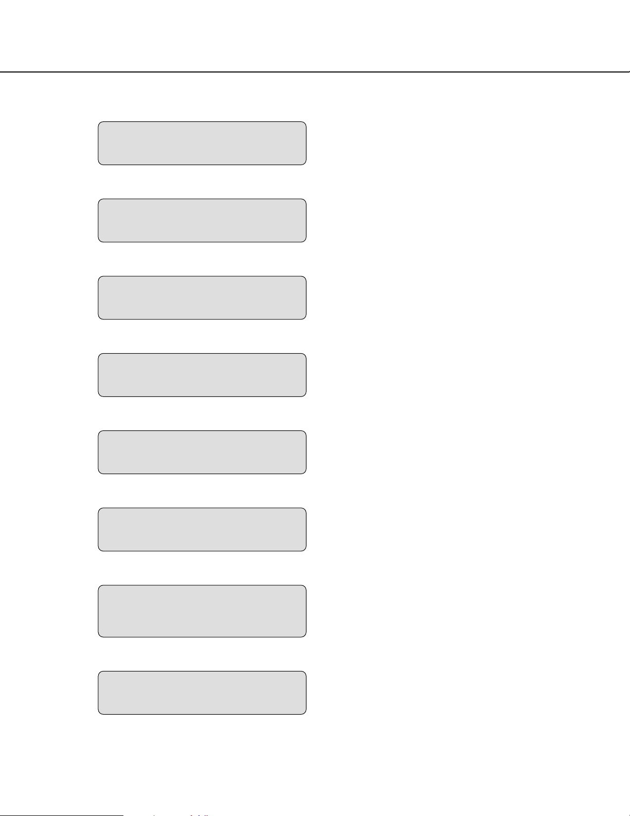
Screenshot 1
Start operation when the standby display is displayed
on the LCD.
OFF
192.168.0.250
255.255.255.0
192.168.1.1
–
OFF
192.168.1.250
255.255.255.0
80
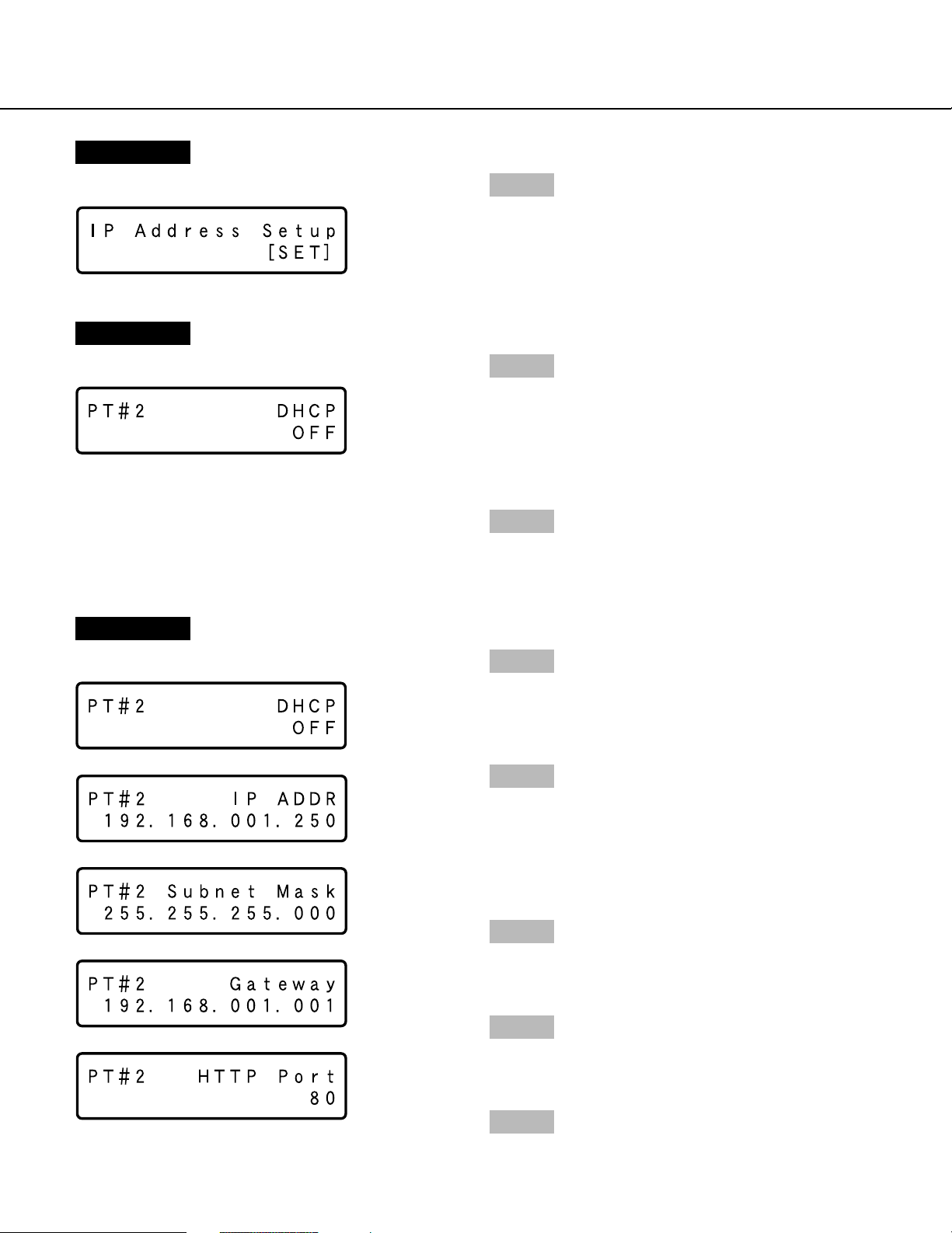
Step 1
Display the IP address setup display by pressing the
arrows button (C or D).
–
192.168.2.250
255.255.255.0
–
–
8
Page 9
>
–
Screenshot 2
The IP address setup display will be displayed.
Screenshot 3
The DHCP Setup window will be displayed.
Step 2
Press the [SET] button.
Step 3
Select the desired network port by pressing the arrows
button (A or B).
PT#1: Camera port
PT#2: Client PC port
PT#3: Maintenance port
Step 4
Display the desired settings item by pressing the arrows
button (C or D).
Screenshot 4
The setup item display for each item will be displayed.
>
–
>
–
>
–
>
–
Step 5
After confirming that the cursor is positioned on "l",
press the [SET] button, and move the cursor to the
number area.
Step 6
Set the value as follows. The cursor appears as a "_"
(underscore).
To move the cursor: Press the arrows button (A) or
(B).
To input values: Press the arrows button (C) or (D).
Step 7
After setting the value, press the [ESC] button to move
the cursor on "l" and finalize the setting.
Step 8
To set the next item, press the arrows button (C) or (D)
to change the menu screen.
>
–
Step 9
Repeat steps 5 – 7 to set other items.
9
Page 10
Performing the Network Settings of a PC
Change the TCP/IP setting of the PC to conform to the settings of this unit.
It is required to set the IP address of the PC to "192.168.1.XX (a number from 2 to 254 except 250)" to access this
unit.
In these operating instructions, the settings are performed on Windows XP as examples. Refer to the operating
instructions of the respective OS for further information.
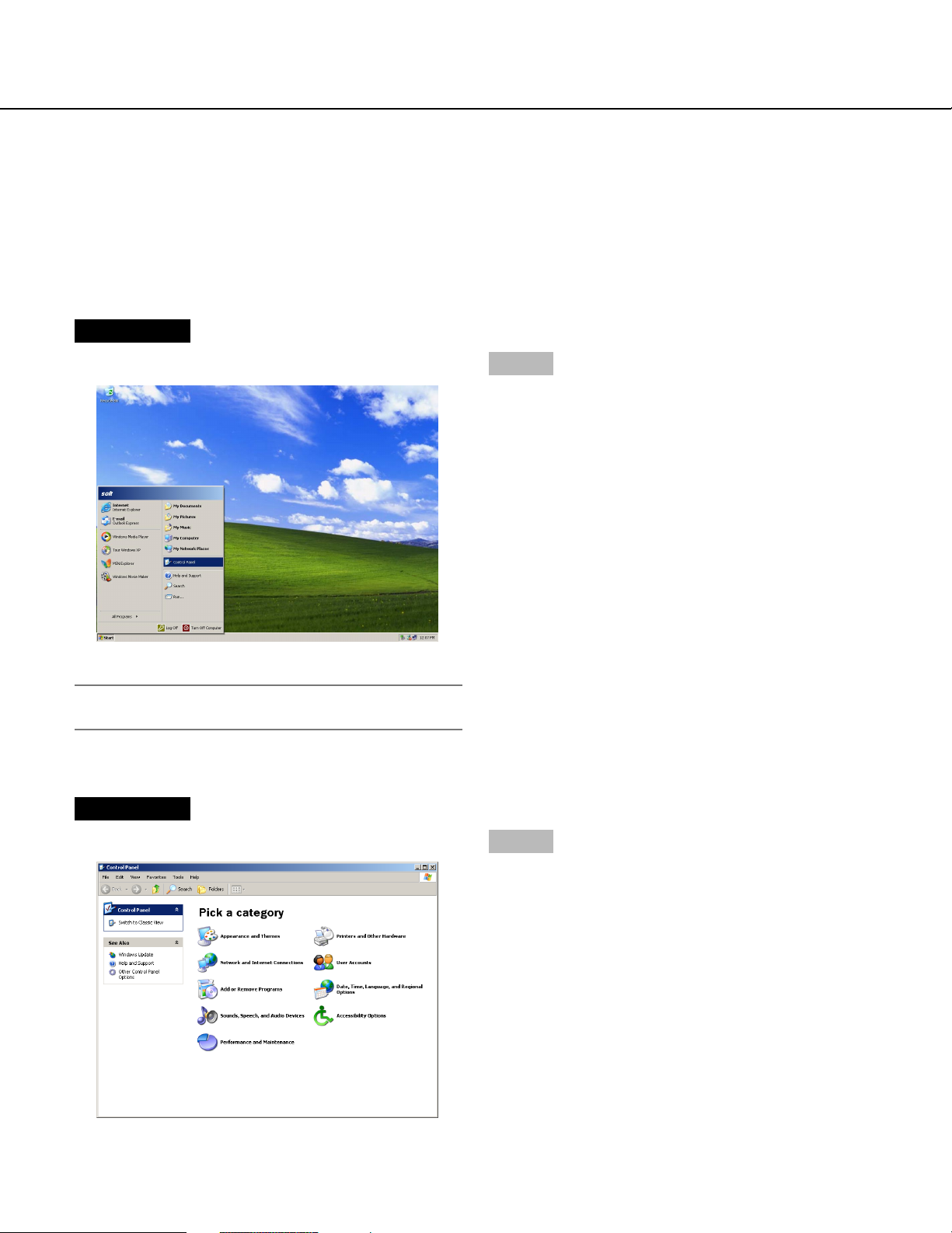
Screenshot 1
Start just after the PC is started up.
Step 1
On the taskbar, click "Start", and then click the "Control
Panel".
Important:
Log in to the PC as an administrator.
Screenshot 2
The control panel will be displayed.
Step 2
Click the "Network and Internet Connections" icon.
10
Page 11
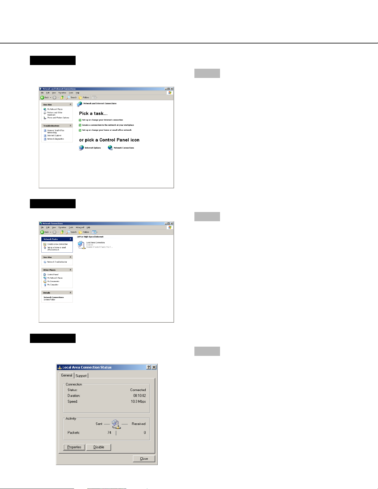
Screenshot 3
The "Network and Internet Connections" window will be
displayed.
Screenshot 4
The "Network Connections" window will be displayed.
Step 3
Click "Network Connections".
Step 4
Double click "Local Area Connection".
Screenshot 5
The "Local Area Connection Status" window will be displayed.
Step 5
Click "Properties".
11
Page 12
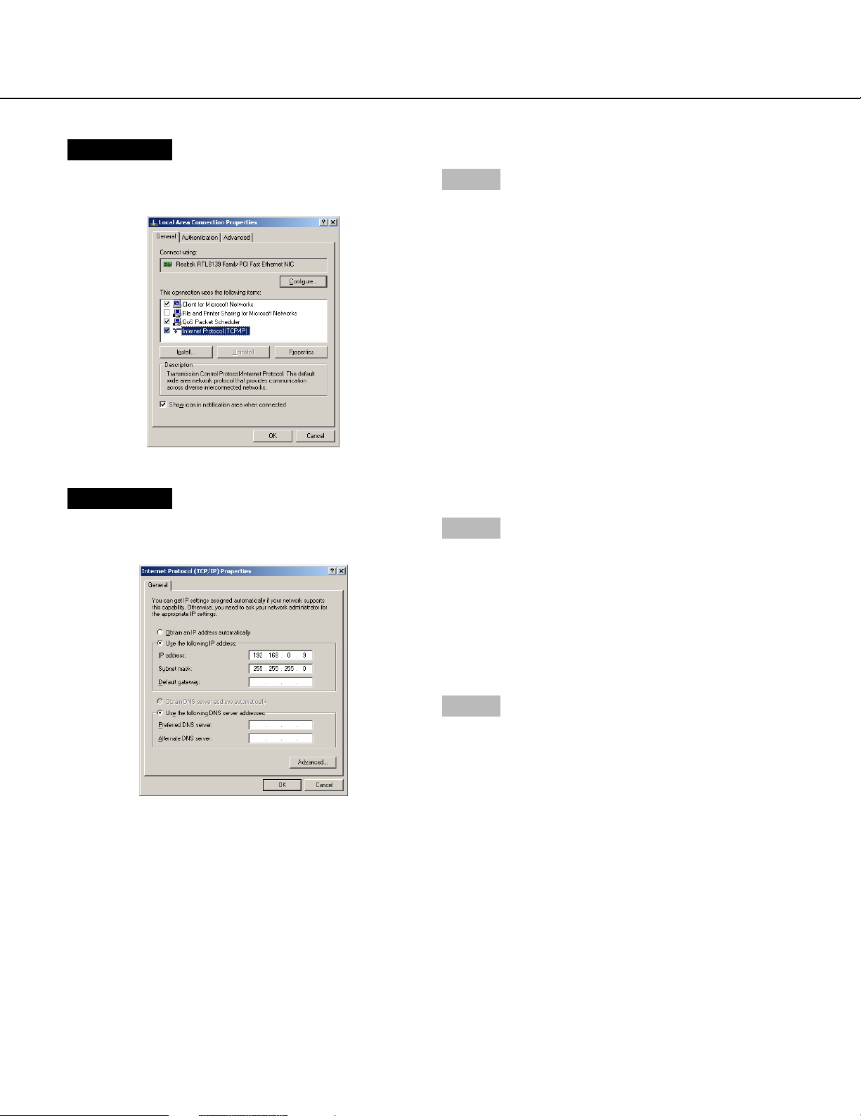
Screenshot 6
The "Local Area Connection Properties" window will be
displayed.
Screenshot 7
The "Properties" window of "Internet Protocol (TCP/IP)"
will be displayed.
Step 6
Click "Internet Protocol (TCP/IP)", and then click
"Properties".
Step 7
Click "Use the following IP address" and enter the IP
address and the subnet mask as follows;
• IP address: 192.168.1.100
• Subnet mask: 255.255.255.0
Depending on the network configuration, it may be necessary to set the "Default gateway". Refer to a system
administrator for further information.
12
Step 8
Click the "OK" button and close the window.
Page 13
About the Network Security of this Unit
Equipped Security Functions
q Access restrictions by the host authentication and the user authentication
It is possible to restrict users from accessing this unit by setting the host authentication and/or the user authentication to on. (page 75)
w Access restrictions by changing the HTTP port
It is possible to prevent illegal access such as port scanning, etc. by changing the HTTP port number. (page 65)
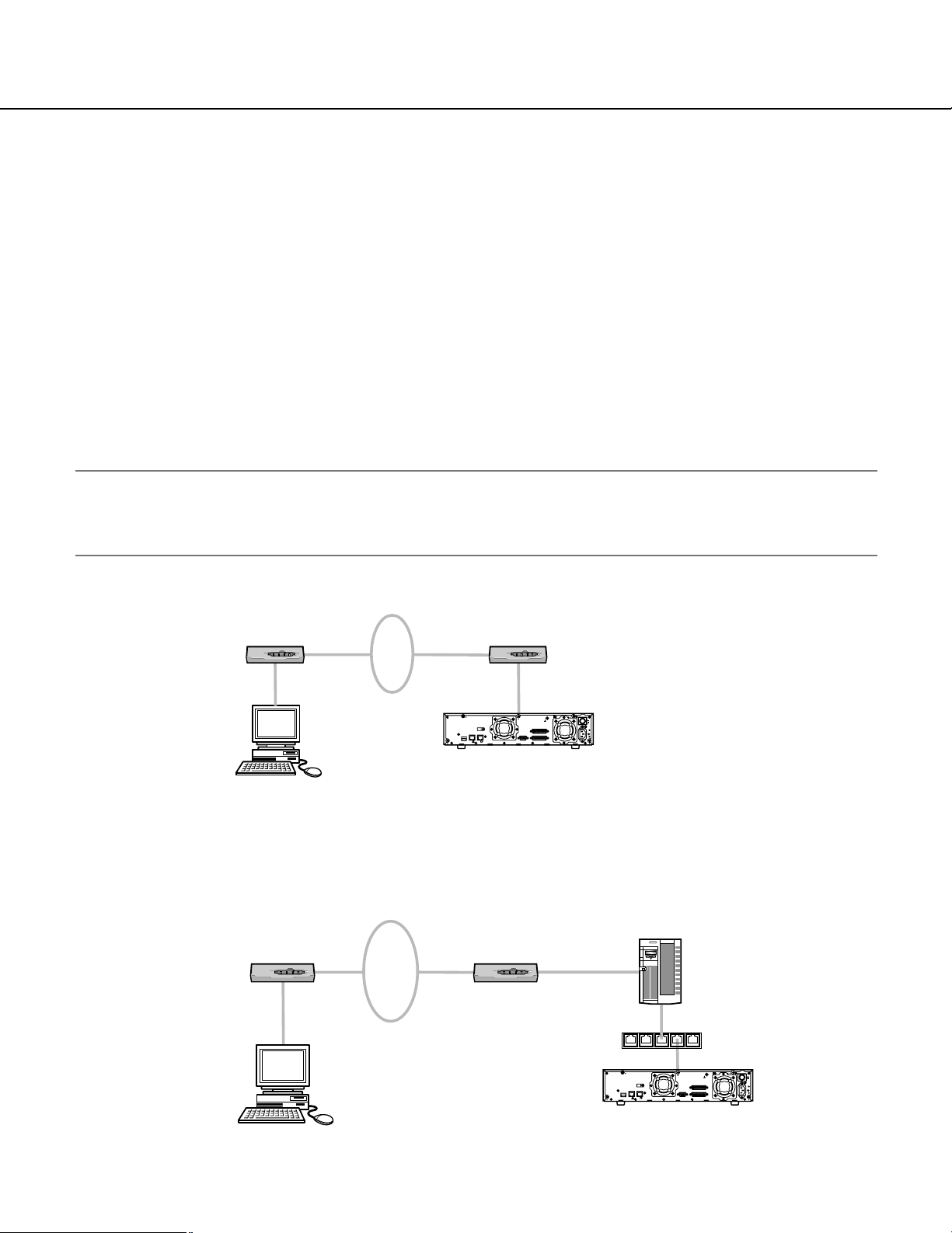
For Enhanced Security
Divide the subnet using a router to enhance the network security by double authentications of IP addresses using
this unit and a router. When required to connect this unit with a network without enhanced security, connect the unit
after the network security is enhanced, such as by installing a VPN (Virtual Private Network) device, etc.
Important:
The settings of the unit will be different depending on the settings of the LAN or the Internet service provider to
which the unit is to be connected. Refer to an administrator of each network for further information about the
respective network.
[Connection example]
Router Router
IP Address: 192.168.0.1
Subnet Mask: 255.255.255.0
IP Address: 192.168.0.100
Subnet Mask: 255.255.255.0
Default Gateway: 192.168.0.1
IBM PC/AT Compatible
WAN*
* Stands for Wide Area Network
10/100BASE-T
21
EXT STORAGE
PC
CAMERA
This unit
IP Address: 192.168.1.1
Subnet Mask: 255.255.255.0
POWER
SIGNAL GND
ALARM
SERIAL
ALARM/CONTROL
ON
OFF
AC IN
IP Address: 192.168.1.250
Subnet Mask: 255.255.255.0
Default Gateway: 192.168.1.1
Installing a firewall to use the packet filtering and the protocol filtering functions can better enhance the network
security.
[Connection example]
Firewall
IP Address: 192.168.0.1
Subnet Mask: 255.255.255.0
IP Address: 192.168.0.100
Subnet Mask: 255.255.255.0
Default Gateway: 192.168.0.1
Router Router
WAN*
* Stands for Wide Area Network
IBM PC/AT Compatible
IP Address: 192.168.1.1
Subnet Mask: 255.255.255.0
EXT STORAGE
10/100BASE-T
21
CAMERA
PC
This unit
Switching hub
POWER
SIGNAL GND
ALARM
ALARM/CONTROL
SERIAL
ON
OFF
AC IN
IP Address: 192.168.1.250
Subnet Mask: 255.255.255.0
Default Gateway: 192.168.1.1
13
Page 14
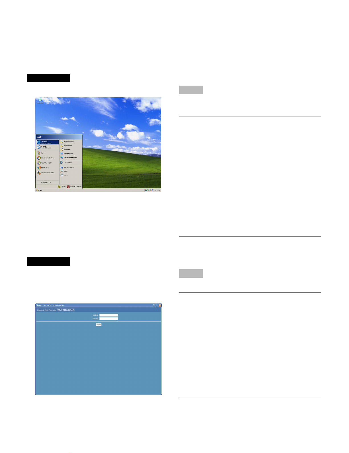
Display the Operation Window
To display the operation window to operate the unit from the web browser installed on the PC, proceed as follows.
Screenshot 1
Start just after the PC is started up.
Step 1
After the browser starts, enter the IP address set to this
unit in the address box, and press the enter key.
Important:
• Refer to a system administrator for the set IP
address of this unit.
• It is impossible to access this unit from a PC without
a registered IP address when "ON" is selected for
"Host Authentication" on the "Basic Setup" of "User
Mng." menu.
Refer to a system administrator for further information.
• Do not attach "0" before the numbers when entering
IP address.
Example
Correct: 192.168.0.50
Wrong: 192.168.0.050
• If a message is displayed on the information bar,
see page 101.
Screenshot 2
The user authentication window will be displayed.
This window will not be displayed when "OFF" is selected for "User Authentication" on the "Basic Setup" of
"User Mng." menu.
Step 2
Enter the user ID and password registered on this unit.
Important:
• Refer to a system administrator for the set user
name and password.
Refer to page 77 for the descriptions of how to register users.
• The default administrator name and password are
as follows.
USER ID: ADMIN
Password: 12345
• To enhance the security, change the password for
an administrator before running the unit. It is recommended to change the password for the administrator periodically. Refer to page 76 for descriptions of
how to change the password.
14
Page 15
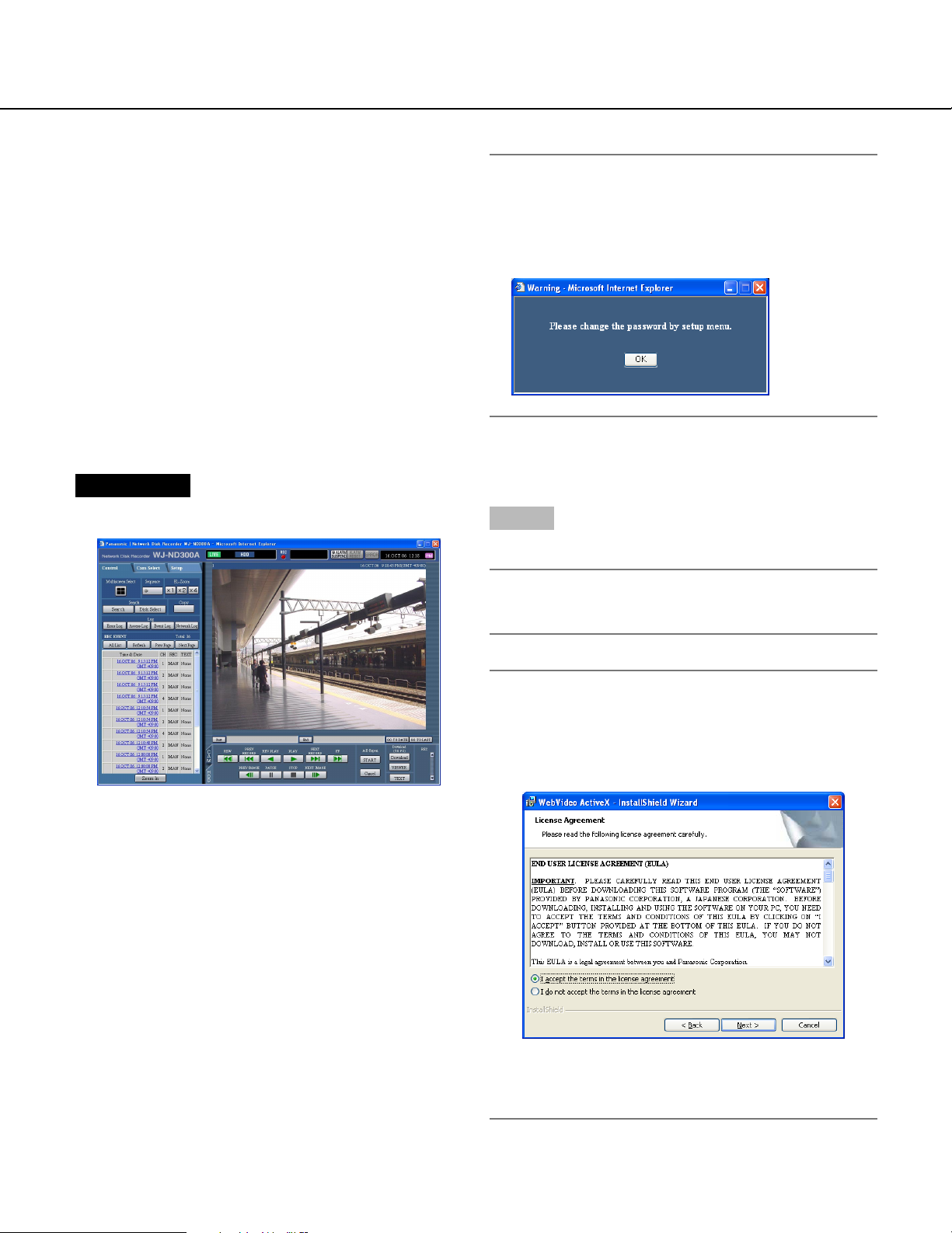
Screenshot 3
The top page will be displayed.
Important:
When the unit is being operated without changing
the default administrator name and password, the
pop-up window saying that it is recommended to
change the password will be displayed.
Step 3
Click the buttons or the tabs for operations.
Important:
If a message is displayed on the information bar,
see page 101.
Note:
When the top page is displayed for the first time, the
install wizard of the ActiveX control required to display images from the camera will be displayed.
Follow the instructions of the wizard.
• When the install wizard is displayed again even
after completing the installation of the ActiveX,
restart the PC.
15
Page 16
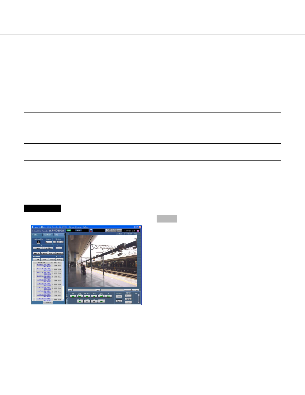
About the Operation Window
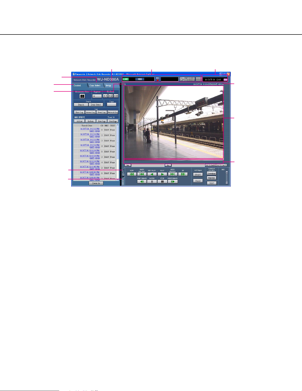
Top Page
[Setup] tab Status display area Current time display area
[Cam Select] tab
[Control] tab
Camera title
[CAM] tab
Time and date of the
selected camera
Playback image
display area
Playback point
operation area
[HDD] tab
[Control] tab (page 17)
This tab is for performing operations such as searching
for recorded pictures on an HDD and copying recorded
pictures into the copy area of the HDD. From this tab,
you can also perform the functions of the camera picture switcher such as changing the display of camera
live pictures to quad or sequence display. Search
results or log information will also be displayed on this
page.
[Cam Select] tab (page 18)
The switcher functions such as switching camera channels are operable on this page.
[Setup] tab (pages 19 and 20)
Operations for setup of this unit can be performed on
this tab. Using the setup menu (Quick) and the setup
menu (Advanced)
Status display area (Page 21)
Current status such as playback status or recording status will be displayed.
Playback image display area
Recorded images and live images will be displayed. The
setup menu will be displayed while setting up.
The camera title is displayed at the top left of the picture
and the time (current camera time for live pictures and
recorded time for recorded pictures) at the top right.
Clicking the camera title during quad display will display
the clicked picture on a single screen.
Playback point operations area (page 23)
It is possible to mark playback points or skip to the latest recorded image.
[HDD] tab (page 23)
Operation for recorded images such as playback or
downloading (saving) recorded images can be performed on this page.
[CAM] tab (page 25)
Perform the camera operations such as zooming, focusing, auto functions, etc. on this panel.
Current time display area
Current time will be displayed.
16
Page 17
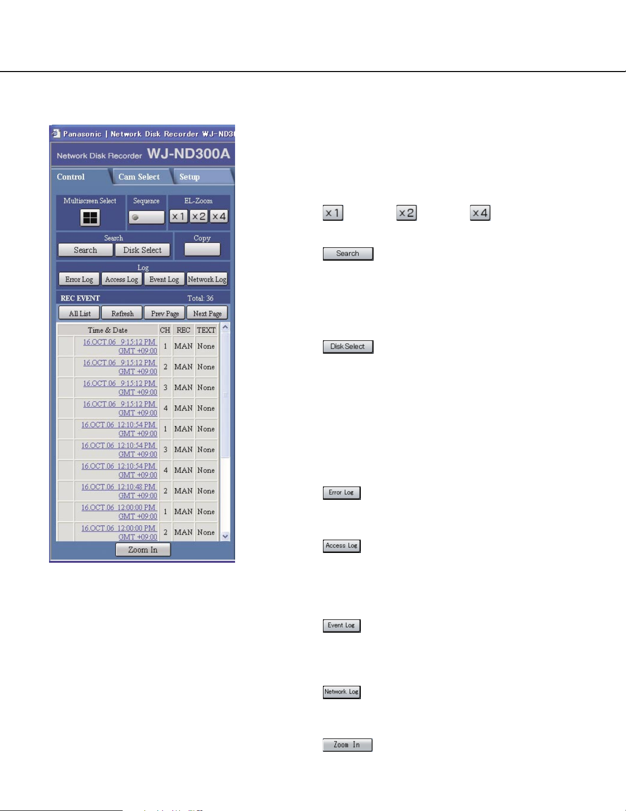
[Control] Tab
The lamp on the button lights (green) during sequence
operation.
[EL-Zoom] box
Camera images will be displayed in the proportion of the
clicked zoom ratio button.
:1x :2x :4x
[Search] box
[Search] button: The recording event
search will be displayed. Use this button to search
the recorded images. (Refer to the Operating
Instructions (PDF).)
Search results will be displayed in list form in the log
display area. (Refer to the Operating Instructions
(PDF).)
[Disk Select] button: The disk select window will be displayed. Use this button to select a
disk to be played/searched. (Refer to the Operating
Instructions (PDF).)
[Multiscreen Select] box
Up to 4 camera images can be displayed simultaneously on a 4-Screen.
Each time the button is clicked, the camera picture is
changed to quad display according to the settings made
in [System] – [Basic Setup] – [Monitor Display] of the
setup menu (Advanced).
[Sequence] box
Camera images to be displayed will be switched by
clicking this button. Camera images will be displayed
sequentially according to the settings performed in
advance.
[Copy] box
The copy window will be displayed by clicking this button. This window is used to copy recorded images into
the copy area of the HDD.
[Log] box
[Error Log] button: The error logs of this unit
will be displayed. Logs will be displayed in list form
in the log display area.
[Access Log] button: The time when logged
in/out for this unit, the user ID, and the IP address
will be displayed.
Logs will be displayed in list form in the log display
area.
[Event Log] button: The event logs (event
occurrence times and their details) will be displayed.
Logs will be displayed in list form in the log display
area.
[Network Log] button: The network error logs
will be displayed.
Logs will be displayed in list form in the log display
area.
[Zoom In]: Enlarges the live camera image
and playback picture.
17
Page 18
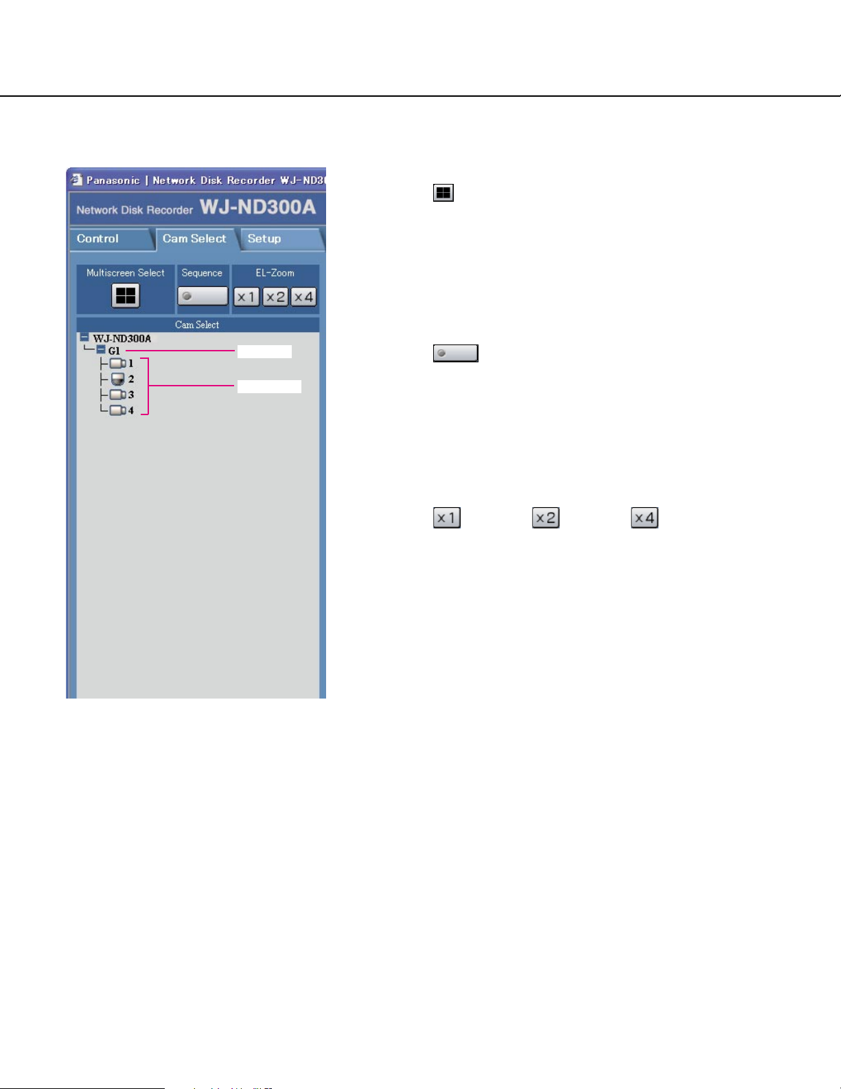
[Cam Select] Tab
Group title
Camera title
[Multiscreen Select] box
Multiscreen button:
Up to 4 camera images can be displayed simultaneously on a multi-screen.
Each time the button is clicked, the camera picture is
changed to quad display according to the settings made
in [System] – [Basic Setup] – [Monitor Display] of the
setup menu (Advanced).
[Sequence] box
Sequence button:
Camera images to be displayed will be switched by
clicking this button. Camera images will be displayed
sequentially according to the settings performed in
advance.
[EL-Zoom] box
Camera images will be displayed in the proportion of the
clicked zoom ratio button.
:1x :2x :4x
[Cam Select] box
Clicking the camera title will display a list of cameras
connected to the unit.
Images from the selected camera channel will be displayed on the image display area by clicking one of
camera names.
18
Page 19
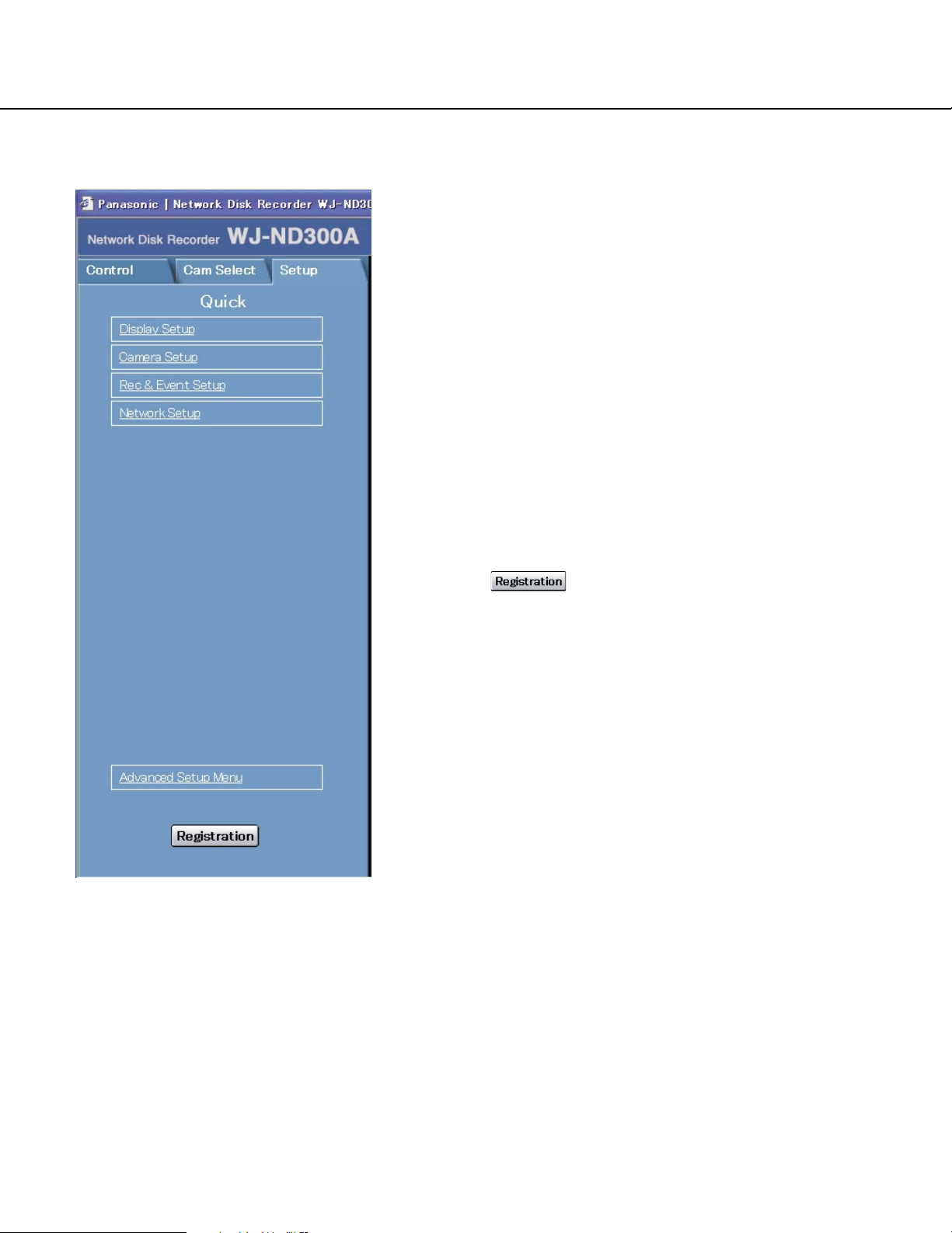
[Setup] Tab (Quick)
Display Setup
This button is for performing basic settings such as
date, time, and language display. Refer to page 28 for
further information.
Camera Setup
This button is for performing camera network settings
and group settings. Refer to page 30 for further information.
Rec & Event Setup
Performs the basic settings for recording operation and
for event action. Refer to page 31 for further information.
Network Setup
Settings for a network can be performed. Refer to page
35 for further information.
[Registration] button
Applies the settings to this unit. Click this button to complete the setting after editing on the setup menu.
19
Page 20
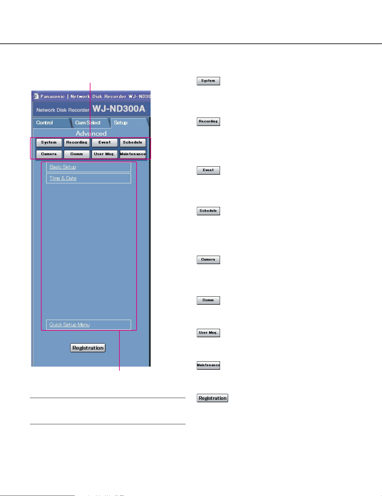
[Setup] Tab (Advanced)
Main menu
[System] button
The menu for the required system settings to activate
this unit will be displayed. Refer to page 42 for further
information.
[Recording] button
The menu for the recording settings will be displayed.
Perform the basic settings for recording and the settings
for emergency recording. Refer to page 46 for further
information.
[Event] button
Displays the setting menu for event actions of each
event type (site alarm, terminal alarm and command
alarm). Refer to page 49 for further information.
[Schedule] button
The menu for the settings of the recording schedule
(performs recording/event action by designating the
time and a day of the week) will be displayed. Refer to
page 53 for further information.
[Camera]
This button is for performing camera network settings,
group settings and sequence operation settings.
Refer to page 60 for further information.
Submenu
Important:
When the settings are applied, all users who have
logged in to this unit will be forcibly logged out.
[Comm] button
The menu for basic network settings will be displayed.
Refer to page 64 for further information.
[User Mng.] button
Displays a menu for registering user information. Refer
to page 75 for further information.
[Maintenance] button
The menu for the settings of the hard disk will be displayed. Refer to page 82 for further information.
[Registration] button
Applies the settings to this unit. Click this button to complete the setting after editing on the setup menu.
20
Page 21
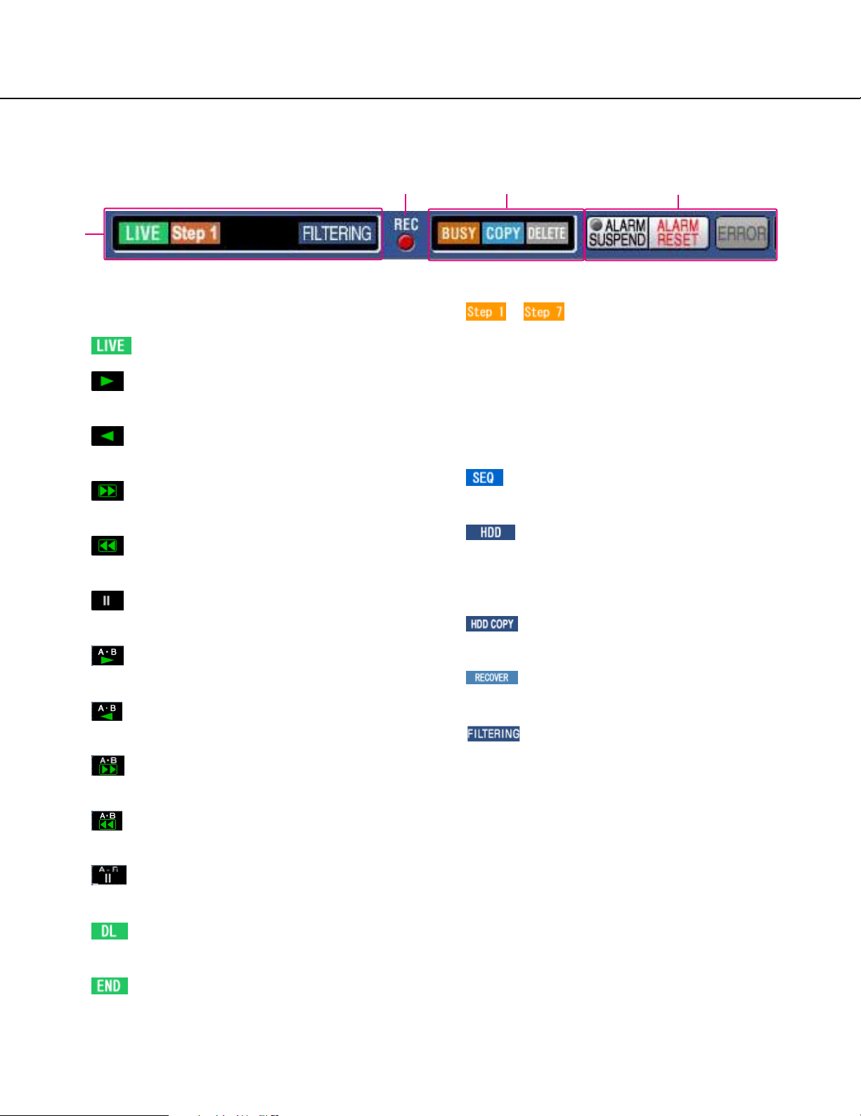
Status Display Area
q
q The status of live/playback image will be
displayed.
(LIVE]:
Indicates that a live image is being displayed.
(Playback):
Indicates that a playback image is being displayed.
(Reverse playback):
Indicates that a reverse playback image is being
displayed.
(Fast playback):
Indicates that a fast playback image is being displayed.
(Fast reverse playback):
Indicates that a fast reverse playback image is
being displayed.
(Pause):
Indicates that a paused image is being displayed.
:
Indicates that the A-B repeat playback mode is
active.
:
Indicates that the A-B repeat reverse playback
mode is active.
:
Indicates that the A-B repeat fast playback mode
is active.
:
Indicates that the A-B repeat fast reverse playback mode is active.
:
Indicates that the A-B repeat pause mode is
active.
[DL]:
Indicates that the playback images are currently
being downloaded.
[END]:
Indicates that download of the playback images
has ended.
w
e
– [Step 1] – [Step 7]:
Indicates the playback speed.
Step 1: Normal playback speed
Step 2: Approx. 4x playback speed
Step 3: Approx. 8x playback speed
Step 4: Approx. 16x playback speed
Step 5: Approx. 32x playback speed
Step 6: Approx. 48x playback speed
Step 7: Approx. 96x playback speed
[SEQ]:
Indicates that the sequence display is currently
being performed.
[HDD]:
Indicates that playback of a recorded image
stored in the normal recording area or the event
recording area of the built-in hard disk of this unit
is currently being selected.
[HDD COPY]:
Indicates that the HDD copy area is currently
being selected.
[RECOVER]:
Indicates that RAID recovery is currently being
performed.
[FILTERING]:
Indicates that the recording event list is filtered.
Refer to the Operating Instructions (PDF) for further information about filtering of the recording
event list.
w Indicator
The status of recording will be displayed.
When lit red: Indicates that recording is being per-
formed.
When not lit: Indicates that recording is not being
performed.
r
21
Page 22

e Indicates the following statuses:
[BUSY]:
Indicates that the camera is not operable
because a user with higher priority is currently
operating that camera.
[COPY]:
Indicates that copying is being performed.
[DELETE]:
Indicates that deletion of a recorded image is
being performed.
r Indicates information about events and errors.
[ALARM SUSPEND]:
Clicking this button will temporarily disable alarm
detection. (Refer to the Operating Instructions
(PDF).)
[ALARM SUSPEND]:
This indication will be displayed while an alarm is
being suspended.
[ALARM RESET]:
Indicates an event occurrence. The alarm display
action will be canceled by clicking this button.
(Refer to the Operating Instructions (PDF).)
[ALARM RESET]:
Indicates no event occurrence.
[ERROR]:
Indicates an error occurrence.
Refer to the Operating Instructions (PDF) for further information about error.
[ERROR]:
Indicates no error occurrence.
22
Page 23
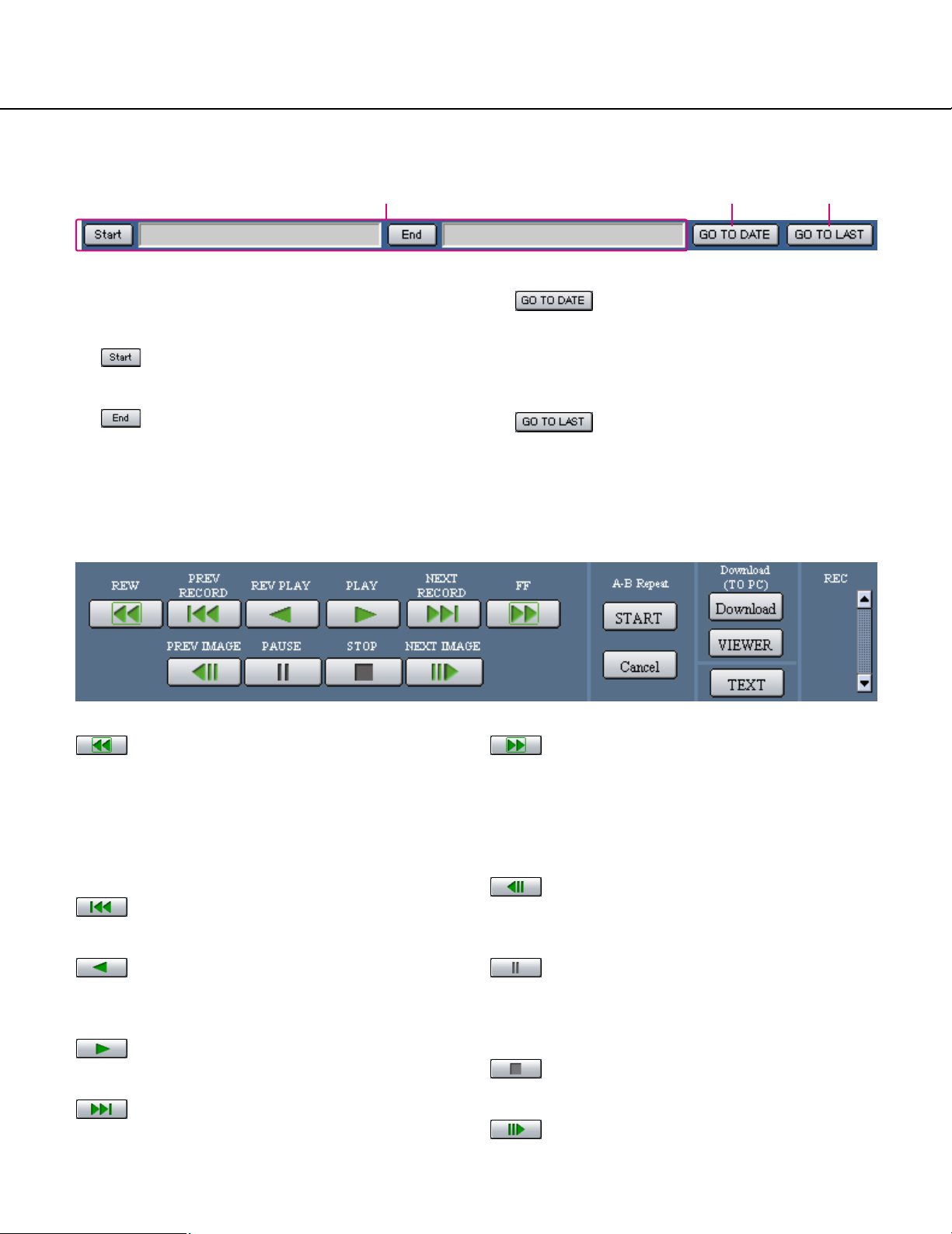
Playback Point Operation Area
q w e
q Indicates the start time and the end time of a down-
load or a A-B repeat. (Refer to the Operating
Instructions (PDF).)
[Start] button
Indicates the start time for the time and date of
the image to be downloaded.
[End] button
Indicates the end time for the time and date of
the image to be downloaded.
[HDD] Tab
[REW] button
Fast reverse playback will be performed. Playback
speed for fast reverse playback will be changed in the
following order each time this button is clicked: Step2
(Approx. 4x) → Step3 (Approx. 8x) →
Step4 (Approx. 16x) → Step5 (Approx. 32x) →
Step6 (Approx. 48x) → Step7 (Approx. 96x)
[PREV RECORD] button
Skips to the previous recorded image and plays it.
w [GO TO DATE] button
Indicates the time and date of a marked point. Use
this button to designate the desired time and date of
a recorded image to be played. (Refer to the
Operating Instructions (PDF).)
e [GO TO LAST] button
Skips to the latest recorded time of a recorded
image from the currently displayed camera channel
and plays it.
[FF] button
Fast playback will be performed. Playback speed will be
changed in the following order each time this button is
clicked: Step2 (Approx. 4x) → Step3 (Approx. 8x) →
Step4 (Approx. 16x) → Step5 (Approx. 32x) →
Step6 (Approx. 48x) → Step7 (Approx. 96x)
[PREV IMAGE] button
The previous frame will be displayed when this button is
clicked during playback/pausing.
[REV PLAY] button
Reverse playback of a recorded image will be performed.
[PLAY] button
Playback of a recorded image will be performed.
[NEXT RECORD] button
Skips to the next recorded image and plays it.
[PAUSE] button
Playback will be stopped when this button is clicked during playback. Playback will be resumed when this button is clicked during pausing.
[STOP] button
Stops playback and displays a live image.
[NEXT IMAGE] button
The next frame will be displayed when this button is
clicked during playback/pausing.
23
Page 24
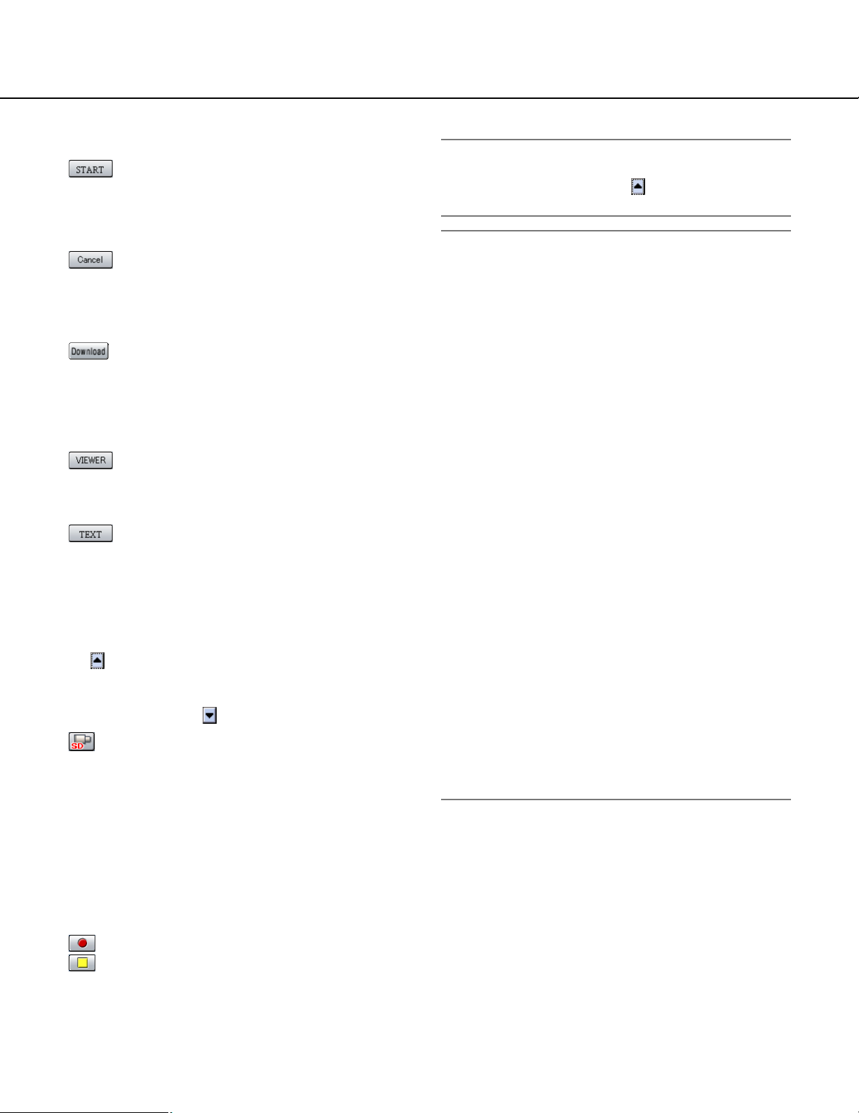
[A-B Repeat] box
The A-B repeat playback will be performed.
[START] button
Starts repeated playback of images between the A-B
repeat start/end points.
Date and time of the A-B start/end points will be displayed in the playback position operations area.
[Cancel] button
The A-B repeat playback will be canceled.
[Download (TO PC)] box
Downloads the image currently playing to a PC.
[Download] button
Displays the download setting window for downloading images.
Date and time of the download start/end points will
be displayed in the playback position operations
area.
[VIEWER] button
Clicking this button will start downloading the viewer
software that can play downloaded images.
[TEXT] button
The attached text information will be displayed when
this button is clicked during pausing.
[REC] box
The recording button, the recording stop button and the
SD memory data obtain button will be displayed when
the button is clicked.
Displaying the recording button, the recording stop button and the SD memory data obtain button will be
unavailable when the button is clicked.
SD memory data obtain button: Obtains
recorded images on the SD memory card on the
camera. The letters "SD" on this button will be displayed
in red when there are recorded images on the SD
memory card. The letters "SD" on this button will be
displayed in blue when there is no recorded image on
the SD memory card. When this button is clicked while
the letters "SD" are displayed in blue, the unit will check
if there is any recorded image on the SD memory card
or not. When a recorded image is found, the letters "SD"
on the SD memory data obtain button will turn red.
Recording button: Starts manual recording.
Recording stop button: Stops manual recording.
Important:
• To display the recording button and the recording
stop button, hold down the button until they are
displayed.
Note:
When played image is in MPEG-4 format, results
from operating the some buttons will be as follows.
[GO TO DATE] button: Playback sometimes may
start from a point several seconds after the designated time and date.
[REV PLAY] button: Some frames of recorded
images will not be displayed. Reverse playback
will be performed with the set refresh interval of
the camera.
[PLAY] button (during playback): When the
[PLAY] button is clicked during playback, images
will be skipped for several seconds. (Playback
will starts from a point several seconds after the
current point.)
[PREV IMAGE] button: Some frames of recorded
images will not be displayed. Reverse frame play
will be performed with the set refresh interval of
the camera.
[FF]/[REW] button: Some frames of recorded
images will not be displayed. Fast playback/fast
reverse playback will be performed with the set
refresh interval of the camera.
[START] button (in the [A-B Repeat] box): Black
screen may be displayed when the A-B repeat
playback is performed.
[Download] button (during playback): Download
may start from a point several seconds later than
the designated start time and may end at a point
several seconds after the designated end time
when downloading MPEG-4 images.
24
Page 25
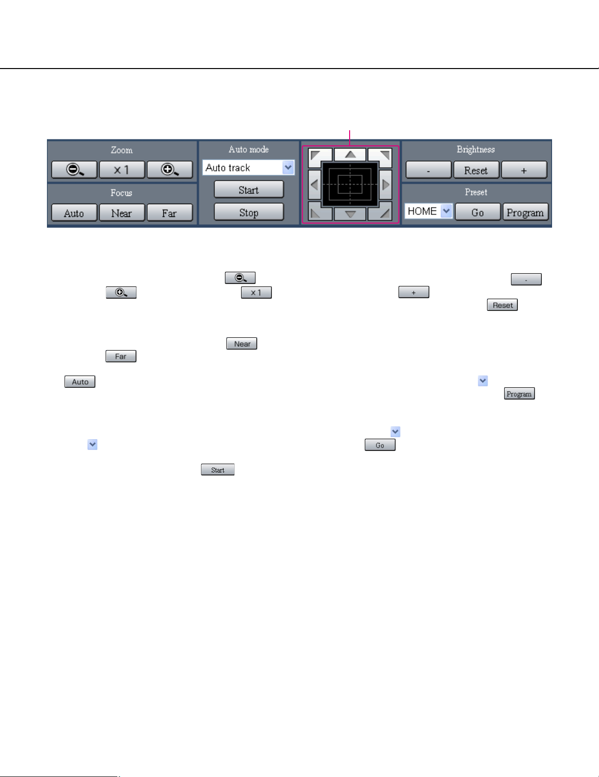
[CAM] Tab
Control pad/buttons
[Zoom] box
Zooming can be adjusted by clicking the [Wide]
button or the [Tele] button. Click the
button to reset zoom.
[Focus] box
Focusing can be adjusted by clicking the [Near]
button or the [Far] button.
The auto focus function can be performed by clicking
the [Auto] button.
[Auto mode] box
This box allows users to select the auto mode function
and operate the camera.
Click the button to select the auto mode function
(Auto Track, Auto Pan, Preset Sequence, Sort, or
Patrol) of the camera, and click the [Start] button.
Control pad/buttons
Clicking the buttons around the control pad can move
(pan/tilt) a camera in the clicked direction. Clicking
inside the control pad also can adjust the vertical/horizontal position (pan/tilt) of the displayed image.
Panning/tilting speed will be faster if a clicked point gets
farther from the center point of the control pad.
[Brightness] box
The brightness can be adjusted by clicking the
[Close] button or the [Open] button. It is possible
to reset the set brightness by clicking the [Reset]
button.
[Preset] box
This box allows users to register the current camera
direction on a specified preset position. Aim the camera
at a direction to be registered, click the button to
select a preset number (1-256), and click the
[Program] button.
Move the camera to the preset position registered in
advance. Click the button to select the preset number
and click the [Go] button.
25
Page 26
Setup Menu (Quick)
Performing each setting item on the setup menu should be completed in advance to operate this unit.
The setup menu operations are performed from the [Setup] tab.
Using the setup menu (Quick) and the setup menu (Advanced). First, check the settings items of the setup menu
(Quick) and perform the settings. When more detailed settings are required, perform the settings on the setup menu
(Advanced). Refer to page 37 for further information about the setup menu (Advanced).
The following are available on the setup menu (Quick).
Setup Menu (Quick) Chart
Setup items
Display Setup
Camera Setup
Rec & Event Setup
Network Setup
Description
Perform the display settings such as the display position of the camera
title and time, and the settings for other basic operations of this unit.
For performing camera network settings and group settings.
Perform the basic settings for recording operation and for event action.
Settings for a network can be performed.
Basic Operation with the Setup Menu (Quick)
Screenshot 1
Start operation from the top page.
Step 1
Click the [Setup] tab.
Page
28
30
31
35
26
Page 27
Screenshot 2
The setup menu (Quick) will be displayed.
Menu
Screenshot 3
The settings page of the selected menu will be displayed in the image display area.
Step 2
Click an item on the setup menu (Quick).
Note:
When "ADVANCED" is selected for "REC Type" of
"Rec & Event Setup" on the setup menu (Quick)
(page 32) the setup menu (Advanced) will be displayed when the [Setup] tab is clicked. In this case,
click "Quick Setup Menu". The top page of the setup
menu (Quick) will be displayed.
Step 3
Perform the settings for each item.
Click the [SET] button after completing the settings.
When the [CLEAR] button is clicked, the contents of the
settings will be cleared.
Step 4
To complete the settings, click the [Registration] button.
→ The settings will be applied.
Important:
• If the settings are applied, all login users will be
forcibly logged out.
• The settings will not be applied by clicking the [SET]
button in step 3. To apply the settings, click the
[Registration] button on the setup menu (Advanced).
• Recording is interrupted for about 4 seconds after
changing the settings and clicking the [Registration]
button.
• If an unnecessary status bar or scroll bar is displayed in the popup window, see page 101.
27
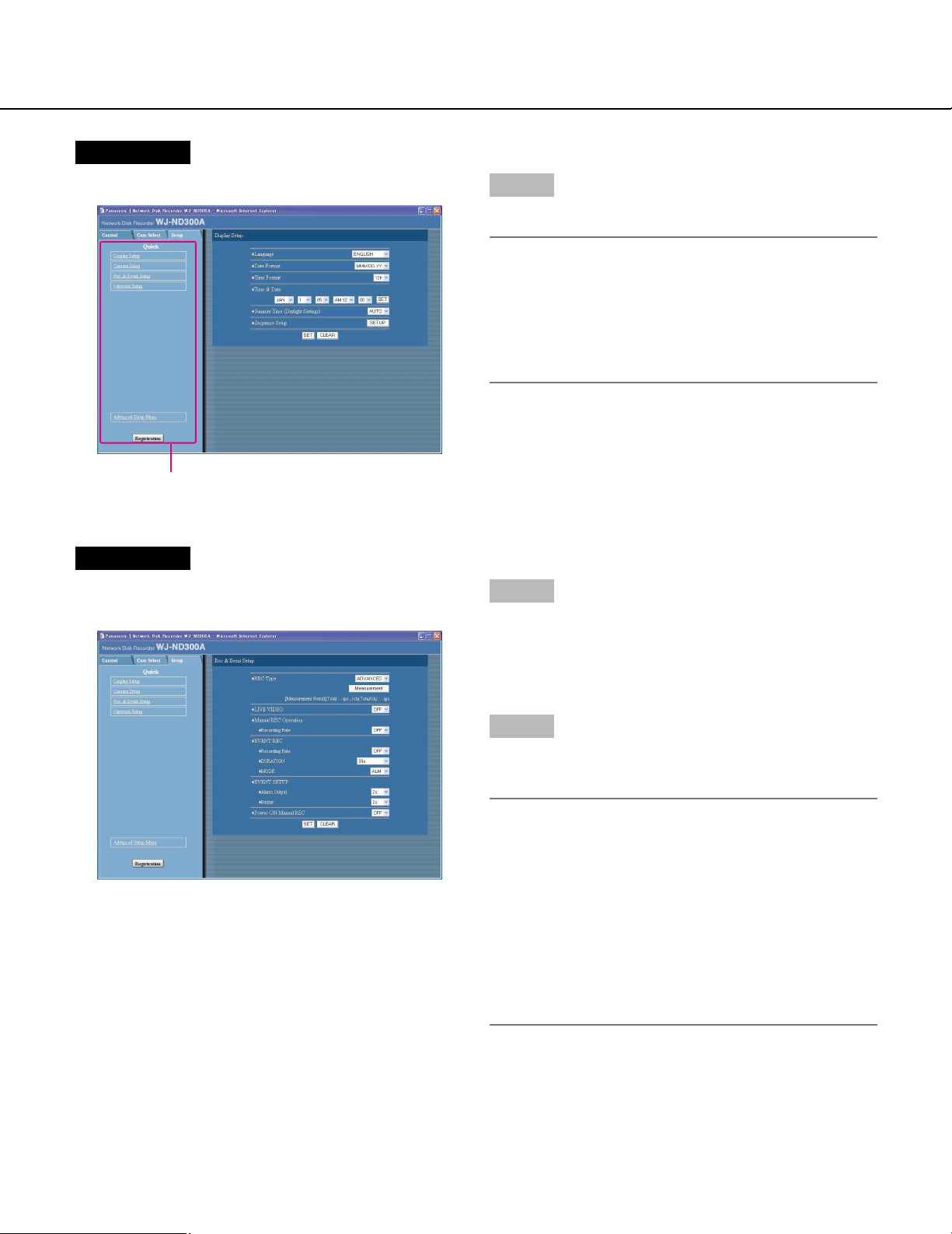
Page 28
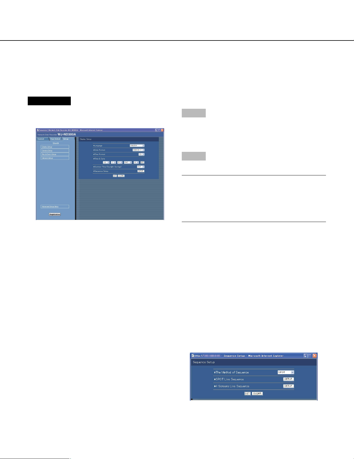
Display/System Settings [Display Setup]
Perform the time and date, display settings such as the time and date display, the camera title display, the sequential display and the language setting.
Screenshot 1
Click "Display Setup" on the setup menu (Quick) to display the display settings window.
Step 1
Perform the settings for each item. Refer to the following for further information about the settings for each
item.
Step 2
Click the [SET] button after completing the settings.
Important:
Live images will turn to black screen and recording
will not be performed for around 4 seconds just after
changing the time and date settings such by editing
the time and date settings or by shifting to/from summertime.
Setup items
■ Language
Select the display language for the web browser from
the following.
JAPANESE/ENGLISH/FRANÇAIS/ESPAÑOL/
DEUTSCH/ITALIANO/RUSSIAN/CHINESE
■ Date Format
Select a date format to be displayed from the following.
Example: (Ex. April 1, 2007)
YY.MM.DD: 07.04.01
MMM.DD.YY: APR.1.07
DD.MMM.YY: 1.APR.07
■ Time Format
Select a time format to be displayed from the following.
(Example for 3 o’clock in the afternoon)
12h: 3:00:00PM
24h: 15:00:00
■ Time & Date
Adjust the current time and date.
Select numbers for year, month, day, hour, minute and
second, and click the [SET] button on the right.
■ Summer Time (Daylight Savings)
Perform the settings for summer time from the following.
OUT: Does not function.
AUTO: Applies summer time in accordance with the set-
ting of summer time. (Refer to pages 44 and 45 for
the descriptions of how to perform the settings.)
■ Sequence Setup
Perform the settings for the sequential display of live
images.
The following window will be displayed when the
[SETUP] button is clicked.
28
Page 29
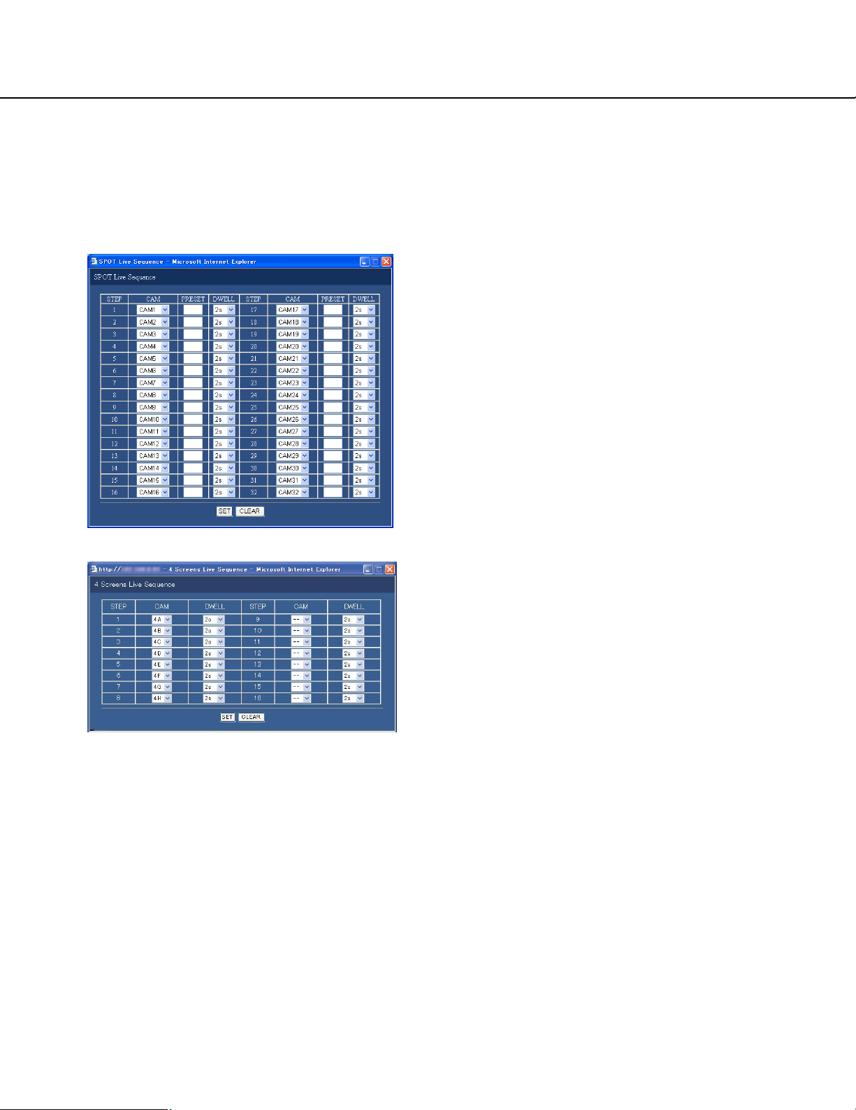
Select "SPOT" or "4 Screens" as the sequence.
Clicking the [SET] button for the selected sequence will
display the following window for setting the various
items. Click the [SET] button after completing the settings, and close the window by clicking the [×] button at
the top right of the window.
[PRESET]
Enter a camera preset position (blank, 1 to 256). When
no position is entered (blank), the camera does not
move to any preset position.
[DWELL]
Select an interval time to go to the next sequential step
from 1 - 30 seconds (in 1 second intervals).
[CAM]
Select a camera image to be displayed at each step
from the following.
--: Skips the selected step.
CAM1 - 32: Displays an image from the selected cam-
era channel on a single screen.
4A - 4H: Switches the images of the preset camera
groups (A – H) of 4 channels in sequence on a 4Screen, starting from A.
Camera groups can be set from [System] – [Basic
Setup] – [Monitor Display] on the setup menu
(Advanced) (page 42).
29
Page 30
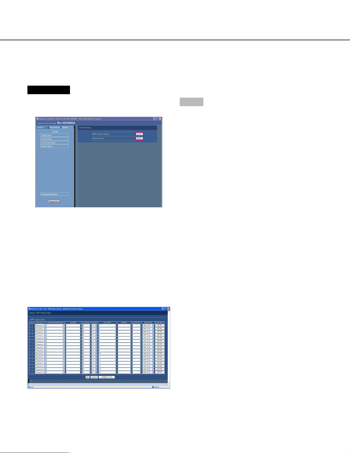
Camera Network Settings and Group Settings [Camera Setup]
Performs network settings such as camera IP address and port number, and group settings.
Screenshot 1
Click "Camera Setup" on the setup menu (Quick) to display the camera setting window.
Step 1
Click the [SETUP] button and perform the settings for
each item.
Refer to the following for further information about the
settings for each item.
Setup items
■ NW Camera Setup
Perform the network camera settings such as the camera IP address and the port number. The following window will be displayed when the [SETUP] button is
clicked.
Click the [SET] button after completing the settings, and
close the window by clicking the [×] button at the top
right of the window.
[Manufacturer]
Select the manufacturer of the camera.
[MODEL/COMPRESSION]
Select a camera number and image compression
method.
[ADDRESS]
Enter an IP address. Enter up to 255 alphanumeric
characters.
[Port Number]
Set the http port number used by the camera. A number
from 1 - 65535 is available.
[GROUP]
Select the group to which the camera is assigned (G1 G8).
[CAM TITLE]
Set the camera title displayed on the [Cam Select] tab,
etc. Enter up to 16 alphanumeric characters except the
following: ! $ % ' < = > @ [ \ ] ^ _ ` { | } ~
30
Page 31

[USER ID]
Set the user ID for accessing the cameras and logging
in. Enter up to 32 alphanumeric characters.
[PASSWORD]
Set the password for accessing the cameras and logging in. Enter up to 32 alphanumeric characters.
[TIME ZONE]
Displays the time zone of the camera.
[CAM SETUP]
Clicking the [SETUP] button of the desired camera will
open the camera setting menu. Opening the camera
setting menu is possible only if [Comm] – [Basic Setup]
- [Port Forwarding] on the setup menu (Advanced) is set
to "ON".
■ Group Setup
Displays the group title of the camera. The following
window will be displayed when the [SETUP] button is
clicked.
Click the [SET] button after completing the settings, and
close the window by clicking the [×] button at the top
right of the window.
Displays the group title of the camera. Enter up to 16
alphanumeric characters except the following: ! $ % ' <
= > @ [ \ ] ^ _ ` { | } ~
Available characters are the same as for the camera
title.
[Rec & Event Setup]
Perform the settings for the basic recording and the settings for event actions of each event type (site alarm, terminal
alarm and command alarm).
Screenshot 1
Click "Rec & Event Setup" on the setup menu (Quick) to
display the recording & event setup window.
Step 1
Perform the settings for each item.
Refer to the following for further information about the
settings for each item.
Step 2
Click the [SET] button after completing the settings.
31
Page 32

Setup items
■ REC Type
Select "QUICK" or "ADVANCED" for validation of the recording settings.
QUICK: The recording settings set on the setup menu (Quick) will be validated when recording.
ADVANCED: The recording settings set on the setup menu (Advanced) will be validated when recording.
It is possible to check if the set recording rate and transmission rate are available for the network in use by clicking
the [Measurement] button. It will take around 90 seconds to check. In the process of measurement, recording and
copying will stop.
When the set rate is displayed red, recording/transmission may be failed with the set rate.
Notes:
• When "QUICK" is selected, the setup menu (Quick) will be displayed by clicking the [Setup] tab. When
"ADVANCED" is selected, the setup menu (Advanced) will be displayed by clicking the [Setup] tab.
• When "QUICK" is selected, the following setup items of "Schedule" (Advanced) will not function. When it is necessary to function the following items, select "ADVANCED".
Submenu
Time Table
Program
Special Days
* To perform the schedule recording, perform the settings for "Time Table" and "Program".
• When "QUICK" is selected, MPEG-4 live image will not be displayed and recording will not be performed.
Check if the result value (total value of the maximum network speed of each camera) is below the maximum network
speed of the unit (50 Mbps as indication).
When the result value is beyond the maximum network speed of the unit (50 Mbps as indication)
(Example: 50 Mbps < 60 Mbps (result value))
When the result value is beyond the maximum network speed of the unit (50 Mbps as indication), refer each rate for
"LIVE VIDEO", "MANUAL REC", "SCHEDULE REC" and "EVENT REC". Then, lower the higher rate among them or
lower image quality to diminish the network traffic from the camera. Click the [Measurement] button to check if the
result value is below the maximum network speed. Repeat this procedure until the result value becomes less than
50 Mbps (as indication).
Setup items Status
"FTP SEND BY PERIODIC TIMER" Disabled
"WARNING REPORT MAIL" Disabled
"FTP ALARM SENDING" Disabled
"ALARM MESSAGE" Functions normally (Fixed to "ON".)
"Panasonic Alarm Protocol" Disabled
"ALARM MAIL" Disabled
Program 1 - 4 The settings performed on the setup menu
(Advanced) will not be validated.
The settings performed on the setup menu
(Quick) will be validated. *
Disabled
32
Page 33

Important
• When the result value is beyond the maximum network speed of the unit, the following may occur due to the
heavy network traffic:
• Some images to be recorded may not be done.
• Some live images to be displayed may not be done.
• Some alarms to be issued may not be done.
• Operational response may become slow.
• The main unit may restart.
• Even when the result value is below the network speed (50 Mbps as indication), the above problems may occur
depending on number of the connected cameras and PCs.
• Network traffic changes every moment. In any circumstances, the result value should be less than the maximum
network speed of the unit (50 Mbps).
JPEG resolution/image
quality
Equivalent to VGA/Low
Number of the
connected cameras
10
Transmission rate
(LIVE VIDEO)
10 ips
Recording rate (*1)
10 ips
Number of the
connected PCs
*2
*25 ips10 ips16Equivalent to VGA/Low
*23 ips3 ips32Equivalent to VGA/Low
*1: Each recording rate for "MANUAL REC", "SCHEDULE REC" and "EVENT REC"
*2: Operation using 2 PCs with a web browser or operation using a single PC with the dedicated software (option)
Notes:
• Click the [Measurement] button after setting the recording rate/transmission rate by clicking the [SET] button.
• Do not change the settings in the process of the measurement.
• In the process of the measurement, recording, playback, live image display and copying will stop. Other users
currently accessing the unit will forcibly be logged out. They need to log in the unit after the measurement.
• The result value is the reference value. Depending on the network traffic, different result value may be displayed
even when the [Measurement] button is clicked without changing the settings.
• Depending on the network traffic or other causes, the following may occur.
• Live images are not transmitted as configured
• Images are not recorded as configured
• Response of the web browser becomes slow
• The web browser is disconnected
• Recording is not carried out
We make no guarantee for any damages incurred by recording malfunction or error occurrence regardless of
what the cause may be.
33
Page 34

■ LIVE VIDEO
Set the transmission rate of live images from cameras.
The following are available for the transmission rate.
OFF/0.1 ips/0.2 ips/0.3 ips/0.5 ips/1 ips/2 ips/3 ips/
5 ips/10 ips/15 ips
■ Manual REC Operation
Perform the recording rate for manual recording.
The following are available for "Recording Rate".
OFF/0.1 ips/0.2 ips/0.3 ips/0.5 ips/1 ips/2 ips/3 ips/
5 ips/10 ips/15 ips
■ EVENT REC
Set the recording rate, recording duration and the event
action mode when an event (site alarm, terminal alarm,
command alarm) occurs.
The following are available for "Recording Rate".
OFF/0.1 ips/0.2 ips/0.3 ips/0.5 ips/1 ips/2 ips/3 ips/
5 ips/10 ips/15 ips
The following are available for "Time" (recording duration).
1 s - 10 s (in 1 second intervals)/20 s/30 s/1 min 10 min (in 1 minute intervals)/20 min/30 min/40 min/
50 min/ 60 min
MANUAL: Recording will be performed while alarm sig-
nals (site alarm, terminal alarm, command alarm)
are being supplied.
CONTINUE: Recording will not stop until the [ALARM
RESET] button is clicked.
Notes:
• When "MANUAL" is selected for "Time" (recording
duration), recording will be performed for at least 8
seconds at an event occurrence as long as the
alarm is not canceled.
• Pre-event recording will not be performed.
■ EVENT SETUP
Perform the settings for the alarm output duration and
the buzzer sound duration at an event (site alarm, terminal alarm or command alarm) occurrence.
The following are available for alarm output duration.
When OFF is selected, the alarm output will not be supplied.
(s: second, min: minute)
1 s - 30 s (in 1 second intervals)/40 s/50 s/1 min/2 min/
3 min/4 min/5 min
EXT: The alarm output will continue until the [ALARM
RESET] button is clicked.
OFF: No alarm output is supplied.
REC: The alarm output will be supplied during recording
is being performed.
The following are available for "Buzzer" (buzzer sound
duration).
When OFF is selected, a buzzer will not sound.
1 s - 30 s (in 1 second intervals)/40 s/50 s/1 min/2 min/
3 min/4 min/5 min
EXT: The buzzer will continue until the [ALARM
RESET] button is clicked.
OFF: The buzzer will not sound.
REC: The buzzer will sound only during recording is
being performed.
■ Power ON Manual REC
Select ON or OFF to determine whether or not to start
recording when the power is turned on by the connected
external timer (or the switch).
ON: Manual recording will start automatically after com-
pleting the system check.
OFF: Manual recording will not start automatically after
completing the system check.
The following are available for the event action mode.
Refer to the Operating Instructions (PDF) for further
information about each event action mode.
ADM (Activity Detection Mode): Performs recording,
preset function and writing an event log at an event
occurrence. Other event actions will not be performed.
ALM (Alarm Mode): Performs recording, preset func-
tion and writing an event log, supplying the alarm
output and sounding the buzzer according to the settings for "Event Setup".
OFF: Performs only recording of the event log. Other
event actions will not be performed.
34
Page 35

Perform the Settings for Network [Network Setup]
Basic settings for a network connection can be performed with this menu.
Screenshot 1
Click the "Network Setup" on the setup menu (Quick).
The "Network Setup" window will be displayed.
Step 1
Perform the settings for each item.
Refer to the following for further information about the
settings for each item.
Step 2
Click the [SET] button after completing the settings.
Setup items
■ NW Link down detection
Select "ON" or "OFF" to enable or disable the network
line disconnection detection for the CAMERA/client PC
port on the rear of the unit.
ON: Detects if the disconnection of the network line
connected to the CAMERA/client PC port occurs.
OFF: Does not detect the network line disconnection.
■ HTTP Port Number
Specify the HTTP port number to be used to send
images from the unit. A number from 1 - 65535 is available.
It is unnecessary to change it for normal use.
Notes:
• Depending on the network settings of the LAN or
Internet service provider, network communication
may not be established if the http port number has
been changed. In this case, refer to the administrator of the network.
• The following port numbers and the port numbers
used for the FTP port, the site alarm settings, and
the port forwarding are unavailable for the HTTP
port number.
20, 21, 23, 25, 42, 53, 67, 68, 69, 79, 80, 105, 110,
123, 161, 162, 546, 547, 995, 10001, 10002, 10003,
10004, 10005, 10006, 10007
■ FTP Port Number
Specify the FTP port number to be used.
Note:
The following port numbers and the port numbers
used for the HTTP port, the site alarm settings, and
the port forwarding are unavailable for the FTP port
number.
20, 23, 25, 42, 53, 67, 68, 69, 79, 80, 105, 110, 123,
161, 162, 546, 547, 995, 10001, 10002, 10003, 10004,
10005, 10006, 10007
35
Page 36

■ Port Setup
Perform the settings for the following items for each
port.
[DHCP]
Select ON or OFF to determine whether or not to use
the DHCP server.
Select "ON" to obtain an IP address, a subnet mask and
a gateway address from the DHCP server. Set to "OFF"
when entering the addresses above manually.
ON: Uses the DHCP server.
OFF: Does not use the DHCP server.
[IP Address]
When "OFF" is selected for "DHCP", enter an IP
address. For this unit, enter 4 units from the decimal
numbers (0-254).
[Subnet Mask]
Enter a subnet mask according to the network configuration when OFF is selected for "DHCP".
[Gateway]
Enter the IP address of the gateway according to the
network environment when "OFF" is selected for
"DHCP".
[Line Speed]
The following are available for "Line Speed".
AUTO: Line speed will be applied automatically.
10-HALF: 10 Mbps semi duplex
10-FULL: 10 Mbps full duplex
100-HALF: 100 Mbps semi duplex
100-FULL: 100 Mbps full duplex
Note:
When the setup menu is closed after changing the
line speed, the unit will automatically restart.
Important:
Set the same line speed for all recorders, PCs and
hubs in use.
Recommended line speed: 100-FULL (100 Mbps
full-duplex)
For example, when "AUTO" is selected for a hub
and "100 Mbps-FULL" is selected for a recorder, display/record/playback of images may not be performed correctly.
36
Page 37

Setup Menu (Advanced) Chart
Performing each setting item on the setup menu should be completed in advance to operate this unit.
The setup menu is operable on this tab.
Using the setup menu (Quick) and the setup menu (Advanced). First, check the settings items of the setup menu
(Quick) and perform the settings. When more detailed settings are required, perform the settings on the setup menu
(Advanced). Refer to page 26 for further information about the setup menu (Quick).
The following are available on the setup menu (Advanced).
Setup Menu (Advanced) Item List
Setup menu Description Page
System
Basic Setup Perform the settings for the basic operations of this unit.
Time & Date Settings for the current time and for displaying the time and date
can be performed.
Recording
REC Setup Basic recording setup can be performed with this menu.
Emergency REC Settings for emergency recording such as the recording time and
recording rate can be performed on this menu.
Event
Basic Setup Settings for an event action can be performed with this menu.
Terminal Setup Set event actions to be performed at a terminal alarm occur-
rence.
Site Alarm Setup Set event actions to be performed at a site alarm occurrence.
Command Alarm Set event actions to be performed at a command alarm occur-
rence.
Schedule
Time Table Create timetables for each day of the week, and assign a pro-
gram to each timetable.
Program Create recording programs on this menu. Up to 4 programs can
be created. Settings for recording actions such as the recording
rate for each camera channel can be performed for each pro-
gram with this menu.
42
43
46
48
49
50
51
52
57
53
Special Days Assign timetables to special days aside from other days of the
week.
Camera
NW Camera Setup Perform the network camera settings such as the camera IP
address and the port number.
Group Setup Displays the group title of the camera.
Sequence Setup Perform the settings for the sequential display of live images.
59
60
62
62
37
Page 38

Setup menu Description Page
Comm
Basic Setup Settings for a network can be performed. Settings for a network
connection such as settings of the IP address and gateway
address can be performed.
DNS Setup Basic network DNS settings can be performed with this menu.
Settings relating to the DNS settings such as the domain name
can be performed.
DDNS Setup Basic network DDNS settings can be performed with this menu.
Determine to enable or disable DDNS, or perform the settings of
the registered user IDs.
Proxy Setup Basic network proxy settings can be performed with this menu.
Determine whether or not to use the proxy server, and perform
the settings such as the server address settings, etc.
SNMP Setup Perform the settings for the SNMP. Perform the settings for the
status check of the unit, etc. by connecting the SNMP manager.
NTP Setup Perform the settings when adjustment of the time is required to
be set with the NTP server such as when setting the NTP server
address.
FTP Setup Perform the settings for the FTP server. Settings for transmitting
images from a camera connected to this unit to a designated
FTP server periodically can be performed with the "FTP Setup"
menu.
64
66
67
68
69
70
71
Mail Setup Perform the settings to send e-mails to addresses registered in
advance at an event or error occurrence.
Panasonic Alarm protocol It is possible to send a message to addresses registered in
advance using "Panasonic Alarm Protocol" when an event or a
problem occurs. To receive messages using this function, the
optional software is necessary.
User Mng.
Basic Setup Configure whether to enable or disable the user authentication
and the host authentication.
Administrator Edit Edit information of the registered administrators such as the
administrator name, password, the default screen, etc.
User Regist. Perform the settings for user registration and user authentication.
User name, password and operational level can be set.
User Edit/Delete Correction or deletion of user information can be performed.
Host Regist. Perform the settings for the host authentication by registering
PCs (hosts) allowed to access this unit via a network.
Operational levels and IP addresses of PCs can be set.
Host Edit/Delete Correction or deletion of host information can be performed.
User Level Functions operable in each user level can be set.
73
74
75
76
77
78
78
79
80
38
Page 39

Setup menu Description Page
Maintenance
Product Information Versions of the software, the hardware (this unit) , MAC address,
temperature inside the unit and software version of the connected extension unit will be displayed.
Disk Information Hard disk information such as available capacity of the built-in
hard disk or an extension unit will be displayed.
Partition Information Available disk space size of the normal area, the event area, the
copy area and the pre-recording areas will be displayed.
Network Information Network information such as IP addresses of the connected
devices, network line speed, the maximum network speed will be
displayed.
Disk End Mode Perform the settings for action when running out of hard disk
space.
HDD Capacity Warning If the available hard disk capacity reaches a specified level, a
warning will be displayed.
Data Delete Data on the hard disk/external recording device will be deleted.
Save/Load Contents of settings for this unit will be saved or loaded.
Config It is possible to check the status of each recording area on the
hard disk drive, and to perform the settings of the hard disk dri-
ves including the initialization (formatting).
82
83
84
85
86
86
87
88
90
39
Page 40

Basic Operation with the Setup Menu (Advanced)
Screenshot 1
Start operation from the top page.
Screenshot 2
The setup menu (Advanced) will be displayed.
Step 1
Click the [Setup] tab.
Step 2
Click the desired setup menu (Advanced).
Main menu
Note:
When "QUICK" is selected for "REC Type" of "Rec &
Event Setup" (page 32) the setup menu (Quick) will
be displayed by clicking the [Setup] tab. In this case,
it is possible to display the setup menu (Advanced)
by clicking "Advanced Setup Menu".
40
Page 41

Screenshot 3
The submenus respective to the clicked button on the
setup menu (Advanced) will be displayed.
Submenu
Screenshot 4
The settings page of the selected submenu will be displayed in the image display area.
Step 3
Click the desired submenu on the setup menu
(Advanced).
Step 4
Perform the settings for each item.
Click the [SET] button after completing the settings.
When the [CLEAR] button is clicked, the contents of the
settings will be cleared.
Step 5
To complete the settings, click the [Registration] button.
→ The settings will be applied.
Important:
• If the settings are applied, all login users will be
forcibly logged out.
• The settings will not be applied by clicking the [SET]
button in step 4 yet. To apply the settings, click the
[Registration] button on the setup menu (Advanced).
41
Page 42

Perform the Settings for the System [System]
Perform the settings for the system of this unit.
Perform the basic settings for the system [Basic Setup]
Perform the settings for the basic operations of this unit.
Screenshot 1
Click the [System] button in the setup menu (Advanced)
and then click "Basic Setup". The "Basic Setup" window
will be displayed.
Step 1
Perform the settings for each item.
Refer to the following for further information about the
settings for each item.
Step 2
Click the [SET] button after completing the settings.
Setup items
■ Language
Select a language to be displayed on the web browser
from the following.
JAPANESE/ENGLISH/FRANÇAIS/ESPAÑOL/
DEUTSCH/ITALIANO/RUSSIAN/CHINESE
■ PASSWORD LOCK
It is possible to lock the buttons on the front panel to
make them unusable. It is necessary to set the password to be used to release the key lock when setting the
key lock.
When the key lock is set once, the buttons on the front
panel will be locked automatically if no operation is performed for around one minute, even after the key lock is
released.
ON: Turn on the key lock function.
OFF: Turn off the key lock function.
Enter up to 5 numbers for the password.
Default password: 12345
Important:
Only the "LV1" user can perform the key lock settings. Refer to page 80 for further information about
the user level.
■ Monitor Display
It is possible to allocate camera channels to each section of a 4-Screen when displaying images on a 4Screen. It is necessary to perform the settings of the
camera group for the sequential display on a 4-Screen
(4A-4H).
The following window will be displayed when the
[SETUP] button is clicked. It is possible to allocate 4
camera channels to each section (4A-4H). The section
where the camera title is displayed will be the image
display section to display images of the respective camera channel.
42
Page 43

■ GO TO LAST before
Select a time to be skipped to when the [GO TO LAST]
button is clicked during playback from the following.
5 s/10 s/30 s/1 min/5 min
■ Buzzer (Error)
Perform the settings for sounding a buzzer at an error
occurrence.
OFF: A buzzer will not sound at an error occurrence.
1 s - 30 s (in 1 second intervals)/40 s/50 s/1 min/3 min/
4 min/5 min (in 1 minute intervals):
The buzzer that started sounding at an error occurrence will sound for the selected period.
EXT: The buzzer will start sounding when a trouble
occurs and it will keep on sounding until the [ALARM
RESET] button is clicked.
■ Shutdown Time
Determine when the safe shutdown starts after a power
outage alert signal is supplied to this unit.
10 s/20 s/30 s/1 min/2 min/3 min/4 min/5 min
Perform the settings for the time and date [Time & Date]
Perform the settings for the time and date.
Screenshot 1
Click the [System] button in the setup menu (Advanced)
and then click "Time & Date". The "Time & Date" window will be displayed.
Step 1
Perform the settings for each item.
Refer to the following for further information about the
settings for each item.
Step 2
Click the [SET] button after completing the settings.
43
Page 44

Setup items
■ Date Format
Select a date format to be displayed from the following.
(Ex. April 1, 2007)
YY.MM.DD: 07.04.01
MMM.DD.YY: APR.01.07
DD.MMM.YY: 01.APR.07
■ Time Format
Select a time format to be displayed from the following.
(Example for 3 o’clock in the afternoon)
12h: 3:00:00PM
24h: 15:00:00
■ Time & Date
Adjust the current time and date.
Select numbers for the year, month, day, hour and
minute, and then click the [SET] button.
Important:
Live images will turn to black screen and recording
will not be performed for around 4 seconds just after
changing the time and date settings such by editing
the time and date settings or by shifting to/from summertime.
Important:
• Recording will not be performed for around 4 seconds when changing the present time (accurate
within ±5 seconds) using the time adjustment input
(pin no.20).
• When "SLAVE" is selected, this function works differently depending on the recording status. For further information, refer to page 20 of the installation
Guide (book).
■ Summer Time (Daylight Savings)
Perform the settings for summer time from the following.
During summertime, the time will be displayed with an
asterisk (*).
OUT: Does not function.
AUTO: Applies summer time automatically in accor-
dance with the settings for switching to summer time
(Refer to the following).
■ TIME ZONE
Displays the time zone of the camera.
■ Auto Adjust Time
Select a method of auto clock adjustment from the following.
OFF: Does not adjust time automatically.
SLAVE: Receives a signal from the MASTER unit and
adjusts the clock.
MASTER: Supplies a from the ALARM/CONTROL con-
nector on the rear panel signal to the other connected devices and the other devices will adjust their
clocks with reference to the clock of this unit.
[Time]
When "MASTER" is selected for "Auto Adjust Time", set
the clock for a signal to be supplied from the ALARM/
CONTROL connector (time adjustment I/O, pin. no. 20)
of the ALARM/CONTROL connector on the rear panel
of the unit. When "SLAVE" is selected, set the time
when the unit receives a signal from the MASTER unit
and adjust the clock.
44
Page 45

■ Summer Time (Daylight Savings) Table
Set the start (ON)/end (OFF) date and time for summer
time.
The following window will be displayed when the
[SETUP] button is clicked. Click the [SET] button after
completing the settings, and close the window by clicking the [×] button at the top right of the window.
Enter the start time and date and the end time and date
of summer time. Enter the last 2 digits of the year.
Up to 10 times and dates for switching to summer time
can be set.
45
Page 46

Functions for Recording [Recording]
Perform the settings for recording. Perform the basic settings for recording and the settings for emergency recording.
Basic settings for recording [REC Setup]
Perform the basic settings for recording.
Screenshot 1
Click the [Recording] button in the setup menu
(Advanced) and then click "REC Setup". The "REC
Setup" window will be displayed.
Step 1
Perform the settings for each item.
Refer to the following for further information about the
settings for each item.
Step 2
Click the [SET] button after completing the settings.
Setup items
■ REC Type
Select "QUICK" or "ADVANCED" for validation of the recording settings.
QUICK: The recording settings set on the setup menu (Quick) will be validated when recording.
ADVANCED: The recording settings set on the setup menu (Advanced) will be validated when recording.
Notes:
• When "QUICK" is selected, the setup menu (Quick) will be displayed by clicking the [Setup] tab. When
"ADVANCED" is selected, the setup menu (Advanced) will be displayed by clicking the [Setup] tab.
• When "QUICK" is selected, the following setup items of "Schedule" (Advanced) will not function. When it is necessary to function the following items, select "ADVANCED".
Submenu
Time Table
Setup items Status
"FTP SEND BY PERIODIC TIMER" Disabled
"WARNING REPORT MAIL" Disabled
"FTP ALARM SENDING" Disabled
"ALARM MESSAGE" Functions normally (Fixed to "ON".)
"Panasonic Alarm Protocol" Disabled
"ALARM MAIL" Disabled
46
Page 47

Submenu Setup items Status
Program
Special Days
* To perform the schedule recording, perform the settings for "Time Table" and "Program".
• When "QUICK" is selected, MPEG-4 live image will not be displayed and recording will not be performed.
■ Recording
Select ON or OFF to record or not record.
OFF: No recording will be performed.
ON: Recording will be performed.
Important:
When OFF is selected for this setting, no recordings will be performed. Select ON for normal use except when
required to stop recording forcibly such as when a problem occurred with the unit.
■ Power ON Manual REC
Select ON or OFF to determine whether or not to start recording when the power is turned on by the connected
external timer (or the switch).
OFF: Manual recording will not start automatically after completing the system check.
ON: Manual recording will start automatically after completing the system check.
Program 1 - 4 The settings performed on the setup menu
(Advanced) will not be validated.
The settings performed on the setup menu
(Quick) will be validated. *
Disabled
47
Page 48

Settings for emergency recording [Emergency REC]
Perform the settings for emergency recording such as the recording time or recording rate. Refer to the provided
operating instructions for further information about emergency recording.
camera channel such as the recording rate or image
Screenshot 1
Click the [Recording] button in the setup menu
(Advanced) and then click "Emergency REC". The
"Emergency REC" window will be displayed.
quality.
The following are available for "Recording Rate". When
OFF is selected for a specified camera channel, images
from a camera channel set to OFF will not be recorded.
OFF/1 ips/2 ips/3 ips/5 ips/10 ips/15 ips/ALL/I-Frame
Note:
The available value differs depending on the selected image compression method. The compression
method can be set on the "MODEL/COMPRESSION" setting of the setup menu ("Camera" – "NW
Camera Setup" – "MODEL/COMPRESSION").
■ SD MEMORY REC
Set the recording rate for the SD memory recording for
each channel. Refer to page 55 for further information
about the SD memory recording.
The following recording rates are available for "SD
MEMORY REC". When OFF is selected, the SD memory recording will not be performed for the respective
channel.
OFF/0.1 ips/0.2 ips/0.3 ips/0.5 ips/1 ips
Step 1
Perform the settings for each item.
■ Recording Duration
Perform the settings for emergency recording such as
the recording time and recording actions.
The following are available for the recording time.
1 s - 10 s (in 1 second intervals)/20 s/30 s/1 min 10 min (in 1 minute intervals)/20 min/30 min/40 min/
50 min/ 60 min
MANUAL: Recording will continue while the external
switch is being held down.
CONTINUE: Recording will not stop until the [ALARM
RESET] button is clicked.
Note:
When "MANUAL" is selected, recording will be performed for at least 8 seconds.
■ Recording Rate
Perform the settings for emergency recording for each
Notes:
• The recording rate setting for "SD MEMORY REC" is
available only for cameras with the SD memory
recording function and their image compression
method is set to "M-JPEG".
• The recording rate for "SD MEMORY REC" should
be less than the recording rate set for the emergency recording.
• When the camera in use is WJ-NT304/WJ-NT314,
recording will be performed at 0.2 ips even when
"0.5ips" or "1ips" is selected for the recording rate for
"SD MEMORY REC".
Important:
When the emergency recording is triggered while
communication with the camera is not established,
the SD memory recording will not be performed.
Step 2
Click the [SET] button after completing the settings.
Important:
Recording will not be performed for around 4 seconds just after the emergency recording.
48
Page 49

Functions for Events [Event]
Perform the settings for event actions of each event type (site alarm, terminal alarm and command alarm). Refer to
the provided operating instructions for further information about each event type.
Basic settings for event actions [Basic Setup]
Perform the settings relating to event actions such as the alarm output duration and the buzzer sound duration of
each camera channel at an event occurrence (site alarm, terminal alarm, command alarm).
Screenshot 1
Click the [Event] button in the setup menu (Advanced)
and then click "Basic Setup". The "Basic Setup" window
will be displayed.
Step 1
Perform the settings for each item.
■ Alarm Output
Select the alarm output duration.
The following are available for alarm output duration.
OFF: No alarm output is supplied.
1 s - 30 s (in 1 second intervals)/40 s/50 s/1 min/2 min/
3 min/4 min/5 min
EXT: The alarm output will continue until the [ALARM
RESET] button is clicked.
REC: The alarm output will be supplied during recording
is being performed.
■ Buzzer
Select ON or OFF to set whether or not to sound the
buzzer at an event occurrence. The following are available for buzzer sound duration.
OFF: The buzzer will not sound.
1 s - 30 s (in 1 second intervals)/40 s/50 s/1 min/2 min/
3 min/4 min/5 min
EXT: The buzzer will continue until the [ALARM
RESET] button is clicked.
REC: The buzzer will sound only during the event
recording is being performed.
Step 2
Click the [SET] button after completing the settings.
49
Page 50

Settings relating to the terminal alarm [Terminal Setup]
Set event actions at a terminal alarm occurrence for each camera channel.
Screenshot 1
Click the [Event] button in the setup menu (Advanced)
and then click "Terminal Setup" to display the "Terminal
Setup" window.
Step 1
Perform the settings for the following items for each terminal alarm channel.
[REC CAM]
Performs the settings for a camera channel used for
recording.
[PRESET]
Enter a preset position (blank, 1-256) to which the camera will move at a terminal alarm occurrence for each
terminal.
When no position is entered (blank), the camera does
not move to any preset position.
[Output Terminal]
Select the output terminal (--, TRM1-TRM16) that outputs alarm signals at a terminal alarm occurrence.
When "--" is selected, alarm signals will not be output.
Step 2
Click the [SET] button after completing the settings.
50
Page 51

Perform the settings for site alarm [Site Alarm Setup]
Perform the settings relating to the site alarm such as the setting to validate or invalidate the original alarm from
cameras, the port number used for receiving the original alarm, and the event actions for each camera channel at an
original alarm occurrence.
Screenshot 1
Click the [Event] button in the setup menu (Advanced)
and then click "Site Alarm Setup" to display the "Site
Alarm Setup" window.
Step 1
Perform the settings for each item.
■ Site Alarm
Select "ON" or "OFF" whether to validate or invalidate
the site alarm.
ON: Validates the site alarm.
OFF: Invalidates the site alarm.
■ Port Number (from Camera)
Designate the port number to be used for receiving the
site alarm.
■ Site Alarm Setup
Perform the settings for the following items for each
camera channel.
[REC CAM]
Performs the settings for a camera channel currently
used for recording.
[PRESET]
Enter a preset position (blank, 1-256) to which the camera will move at an alarm occurrence.
When no position is entered (blank), the camera does
not move to any preset position.
[Output Terminal]
Select the output terminal (--, TRM1-TRM16) that outputs alarm signals at an alarm occurrence. When "--" is
selected, alarm signals will not be output.
Step 2
Click the [SET] button after completing the settings.
51
Page 52

Perform the settings for command alarm [Command Alarm]
Set event actions at a command alarm occurrence for each camera channel.
Screenshot 1
Click the [Event] button in the setup menu (Advanced)
and then click "Command Alarm" to display the
"Command Alarm" window.
Step 1
Perform the settings for the following items for each
command alarm channel.
[REC CAM]
Performs the settings for a camera channel used for
recording.
[PRESET]
Enter a preset position (blank, 1-256) to which the camera will move at an alarm occurrence.
When no position is entered (blank), the camera does
not move to any preset position.
[Output Terminal]
Select the output terminal (--, TRM1-TRM16) that outputs alarm signals at an alarm occurrence. When "--" is
selected, alarm signals will not be output.
Step 2
Click the [SET] button after completing the settings.
52
Page 53

Settings for the Recording/Event Schedule [Schedule]
Perform the settings for the recording schedules by designating a day of the week and time.
It is possible to divide a day into 6 time zones and create a schedule by assigning programs to each time zone. Up
to 4 programs can be created. Perform the settings for programs such as recording rate, recording duration, etc.
It is possible to create special days apart from the normal schedule, and a recording program of another day of the
week can be switched to a special day’s program automatically.
Flowchart on how to create a schedule
Follow the procedures below to create schedules.
Creating a program
Create a timetable.
Assign a program to a timetable.
(page 53)
(page 57)
(page 57)
Creating a recording program [Program]
Up to 4 recording programs can be created by performing the settings for each camera such as resolution, image
quality, bandwidth control, etc.
Screenshot 1
Click the [Schedule] button in the setup menu
(Advanced) and then click "Program" to display the
"Program" window.
Step 1
Click the respective [SETUP] button for the desired program to create a recording program.
53
Page 54

Screenshot 2
The "Program Setup" window will be displayed.
Setup items
Step 2
Perform the settings for each item.
Refer to the following for further information about the
settings for each item.
When the [camera 17-32] button is clicked, the setting
window for camera 17-32 will be displayed.
Step 3
Click the [SET] button after completing the settings, and
close the window by clicking the [×] button at the top
right of the window.
■ Copy the Other Program Setup
When it is necessary to copy the settings of the other
program, select the desired program (source of the settings) and click the [Copy] button.
Important:
Only the currently displayed page (the selected program) can be copied.
■ RECORDER SETUP
Perform the settings such transmission rate of "LIVE
VIDEO" for each camera channel, and recording rate of
each recording type, etc.
[LIVE VIDEO]
Select the transmission rate of live images.
When OFF is selected, live image transmission will not
be performed.
OFF/0.1 ips/0.2 ips/0.3 ips/0.5 ips/1 ips/2 ips/3 ips/
5 ips/10 ips/15 ips/ALL/I-Frame
[MANUAL REC]
Select the recording rate for manual recording.
OFF/0.1 ips/0.2 ips/0.3 ips/0.5 ips/1 ips/2 ips/3 ips/
5 ips/10 ips/15 ips/ALL/I-Frame
OFF: Manual recording will not be performed.
[EVENT REC]
Performs the settings for the recording rate and recording duration for pre-event recording and post-event
recording.
The following are available for "RATE" (recording rate).
0.1 ips/0.2 ips/0.3 ips/0.5 ips/1 ips/2 ips/3 ips/5 ips/
10 ips/15 ips/ALL/I-Frame
OFF: No recording will be performed.
Important:
• Perform the camera settings as follows for pre-event
recording in MPEG-4.
• Refresh interval: 1 sec. or more
• Bit rate per client: 4 096 kbps or less
Failure to observe the above may cause the recording duration of the recorded data to be different from
the set recording duration for the pre-event recording.
• Depending on the network environment or the size
of images to be recorded, the recording duration of
the recorded data may not be exactly same as set
recording duration for the pre-event recording.
• Depending on the timing of an event occurrence, the
recording duration of the recorded data may not be
exactly same as set recording duration for the postevent recording.
[SCHEDULE REC]
Select the recording rate for schedule recording from
the following.
OFF/0.1 ips/0.2 ips/0.3 ips/0.5 ips/1 ips/2 ips/3 ips/
5 ips/10 ips/15 ips/ALL/I-Frame
OFF: Schedule recording will not be performed.
54
Notes:
• "ALL" is unavailable for the recording rate of preevent recording when the compression method of
the camera is MPEG-4.
Page 55

• When the image compression method of the camera
is "MPEG-4" or when selecting "0.5 ips" or less for
the recording rate, it is necessary to select "10 s" or
longer for the recording duration.
The following recording duration can be set.
• Pre-event recording (PRE-EVENT)
1 - 10 s (in 1-second interval)/20 s/30 s/1 - 10 min
(in 1-minute interval)/20 - 60 min (in 10 minutes
intervals)
• Post-event recording (POST-EVENT)
1 - 10 s (in 1-second interval)/20 s/30 s/1 - 10 min
(in 1-minute interval)/20 - 60 min (in 10-minutes
interval)
MANUAL: Recording will be performed while alarm
signals (site alarm, terminal alarm, command
alarm) are being supplied.
CONTINUE: Recording will not stop until the
[ALARM RESET] button is clicked.
Note:
When "MANUAL" is selected for "DURATION"
(recording duration), recording will be performed for
at least 8 seconds at an event occurrence as long as
the alarm is not canceled.
■ SD MEMORY REC
Set the recording rate for the SD memory recording for
each channel.
The following recording rates are available for "SD
MEMORY REC". When OFF is selected, the SD memory recording will not be performed for the respective
channel.
OFF/0.01 ips/0.02 ips/0.03 ips/0.05 ips/0.1 ips/0.2 ips/
0.3 ips/0.5 ips/1 ips
Notes:
• The recording rate setting for "SD MEMORY REC" is
available only for cameras with the SD memory
recording function and their image compression
method is set to "M-JPEG".
• When the camera in use is WJ-NT304/WJ-NT314,
recording will be performed at 0.2 ips even when
"0.5ips" or "1ips" is selected for the recording rate for
"SD MEMORY REC".
■ About the SD memory recording
The SD memory recording is the function of some
Panasonic’s cameras that saves images on the SD
memory card on the camera when communication with
the camera failed in the period set for the schedule
recording of this unit.
For example, when "0.1 ips" is selected for the recording rate for "SD MEMORY REC", images will be recorded on the SD memory card on the camera if no request
(image inquiry) is made from the unit to the camera in
the period of 10 seconds (equivalent to 0.1 ips*) or more
during the time range set for a schedule.
* The start time of the SD memory recording differs
depending on the set recording rate.
There are two ways to obtain recorded images from the
SD memory card; automatic obtainment by adjusting
time length between schedules and manual obtainment
by clicking the SD memory data obtain button.
When time length between the set schedules is longer
than 30 minutes, images recorded by the SD memory
recording will be obtained automatically. All users will
forcibly be logged out when automatic obtainment
starts.
To obtain SD memory data automatically, set time
length between the schedules longer than 30 minutes.
Refer to the operating instructions (PDF) for how to
obtain images manually.
Important:
• The emergency recording will be performed at the
recording rate set for "SD MEMORY REC" on the
"Emergency REC" window when communication
with the camera failed during the emergency recording.
• The SD memory recording will not be performed if
communication with the camera is not established
even when it reached the start time of the schedule
recording or when the emergency recording is triggered.
• Do not set the recording rate of the SD memory
recording for the same camera with multiple
recorders.
• The recording time of SD memory data will be
recorded based on the clock of the camera. To prevent a time contradiction, match the clocks of the
camera and the WJ-ND300 using the NTP function.
Note:
All images recorded on the SD memory card may
not always be obtained at a time depending on the
time length between the schedules or the total size
of the images. Images failed to obtain can be
obtained automatically next time.
55
Page 56

■ [Measurement] button
It is possible to check if the set recording rate and transmission rate are available for the network in use by
clicking this button. It will take around 90 seconds to
check. In the process of measurement, recording and
copying will stop.
When the set rate is displayed red, recording/transmission may be failed with the set rate.
Check if the result value (total value of the maximum
network speed of each camera) is below the maximum
network speed of the unit (50 Mbps as indication).
When the result value is beyond the maximum network
speed of the unit (50 Mbps as indication)
(Example: 50 Mbps < 60 Mbps (result value))
When the result value is beyond the maximum network
speed of the unit (50 Mbps as indication), refer each
rate for "LIVE VIDEO", "MANUAL REC", "SCHEDULE
REC" and "EVENT REC". Then, lower the higher rate
among them or lower image quality to diminish the network traffic from the camera. Click the [Measurement]
button to check if the result value is below the maximum
network speed. Repeat this procedure until the result
value becomes less than 50 Mbps (as indication).
Important
• When the result value is beyond the maximum network speed of the unit, the following may occur due
to the heavy network traffic:
• Some images to be recorded may not be done.
• Some live images to be displayed may not be
done.
• Some alarms to be issued may not be done.
• Operational response may become slow.
• The main unit may restart.
• Even when the result value is below the network
speed (50 Mbps as indication), the above problems
may occur depending on number of the connected
cameras and PCs.
• Network traffic changes every moment. In any circumstances, the result value should be less than the
maximum network speed of the unit (50 Mbps).
JPEG resolution/image
quality
Equivalent to VGA/Low
Number of the
connected cameras
10
Transmission rate
(LIVE VIDEO)
10 ips
Recording rate (*1)
10 ips
Number of the
connected PCs
*2
*25 ips10 ips16Equivalent to VGA/Low
*23 ips3 ips32Equivalent to VGA/Low
*1: Each recording rate for "MANUAL REC", "SCHEDULE REC" and "EVENT REC"
*2: Operation using 2 PCs with a web browser or operation using a single PC with the dedicated software (option)
Notes:
• Click the [Measurement] button after setting the recording rate/transmission rate by clicking the [SET] button.
• Do not change the settings in the process of the measurement.
• In the process of the measurement, recording, playback, live image display and copying will stop. Other users
currently accessing the unit will forcibly be logged out. They need to log in the unit after the measurement.
• The result value is the reference value. Depending on the network traffic, different result value may be displayed
even when the [Measurement] button is clicked without changing the settings.
• Depending on the network traffic or other causes, the following may occur.
• Live images are not transmitted as configured
• Images are not recorded as configured
• Response of the web browser becomes slow
• The web browser is disconnected
• Recording is not carried out
We make no guarantee for any damages incurred by recording malfunction or error occurrence regardless of
what the cause may be.
56
Page 57

Set the time zone and assign programs [Time Table]
Create recording timetables for each day of the week, and assign a recording program to each timetable. Up to 6
recording programs can be created for each day of the week.
Screenshot 1
Click the [Schedule] button in the setup menu
(Advanced) and then click "Time Table" to display the
"Time Table" window.
Step 1
Click the button of the desired day of the week.
Note:
When a signal is supplied from the ALARM/CONTROL connector on the rear panel (external recording mode changeover terminal, pin No. 24), recording is performed according to the "external recording" timetable while the signal input continues.
Screenshot 2
The timetable of the selected day of the week will be
displayed.
Screenshot 3
The "Time Table" window will be displayed again.
Step 2
Perform the settings for each item.
Refer to the following for further information about the
settings for each item.
Step 3
Click the [SET] button after completing the settings.
Step 4
The set timetables and programs will be applied.
Programs will be displayed with different colors.
Program1: Yellow
Program2: Green
Program3: Pale purple
Program4: Dark blue
Note:
To obtain SD memory data automatically, set time
length between the schedules longer than 30 minutes.
However, if the timetable is set for "EXT" only, SD
memory data will not be obtained automatically.
57
Page 58

Setup items
■ Copy the other Time Table
When it is necessary to copy the timetable of another
day of the week, select the desired day of the week and
click the [Copy] button.
■ New Time Table Setup
Perform the settings of the following item for each time
zone.
[START]
Set the start time of the time zone.
[END]
Set the end time of the time zone.
[Program]
Select the desired "Program".
[MODE]
Select the alarm mode to be activated at an alarm
occurrence from the following.
ADM (Activity Detection Mode): Performs only record-
ing, writing an event log and camera movement to a
preset position at an event occurrence. Other event
actions will not be performed.
ALM (Alarm Mode): Performs every event action
according to the settings.
OFF: Performs only recording of the event log. Other
event actions will not be performed.
[FTP Send by Periodic Timer]
Perform the "FTP Send by Periodic Timer" settings of
the setup menu ("Comm" – "FTP Setup") first (page 71),
and select "ON" or "OFF" to determine whether or not to
send images to the FTP server periodically.
[FTP Send by Alarm]
Select "ON" or "OFF" to determine whether or not to
send images to the FTP server at an event occurrence.
(page 72)
[ALARM MESSAGE]
Select "ON" or "OFF" to determine whether or not to display the pop-up window that notify of an alarm occurrence with a message when an alarm occurs.
[Panasonic protocol]
Select "ON" or "OFF" to determine whether or not to
notify of an alarm occurrence (or error information) to a
PC according to the "Panasonic Alarm protocol" of the
setup menu ("Comm" – "Panasonic Alarm protocol")
(page 74).
To receive a notification (or error information) and display the contents of the notification, the optional software is necessary.
[ALARM MAIL]
Select ON or OFF to determine whether or not to send
an alarm mail at an event occurrence.
Refer to page 73 for descriptions of how to use the mail
function such as the settings of the mail server address
and the mail address of the recipient. Refer to the
Operating Instructions (PDF) for further information
about the contents of the alarm mail.
[WARNING REPORT MAIL]
Select ON or OFF to determine whether or not to send
an error mail when a problem occurred. Refer to page
73 for descriptions of how to use the mail function such
as the settings of the mail server address and the mail
address of the recipient. Refer to the Operating
Instructions (PDF) for further information about the
warning report mail.
Notes:
• The start time and end time can be set in 1 minute
intervals. (The end time should be at least 15 minutes later than the start time.)
• Time from "23:46" to "23:59" are unavailable for the
start time.
• To copy a timetable that is set for a different day of
the week, select "Copy the Other Time Table" and
select a day of the week in step 2.
• When the [CLEAR] button is clicked in step 2, the
settings will be canceled.
• Repeat steps 1-4 to set programs of another day of
the week.
58
Page 59

Perform the settings of recording programs for special days [Special Days]
Assign timetables to special days aside from other days of the week. Timetables for special days can be set for up to
30 days.
Perform the settings to specify dates as special days and apply a recording schedule to the specified special days.
Screenshot 1
Click the [Schedule] button in the setup menu
(Advanced) and then click "Special Days" to display the
"Special Days" window.
Step 1
Click the [i] button and select date to be set as special
day and the day of the week of the recording program to
be assigned to the special day.
Step 2
Click the [SET] button after completing the settings.
Note:
When two or more created programs (programs for
each day of the week, daily and special day) are set
in the same time range, the recording priority will be
as follows: External recording (EXT) → Special days
→ Day of the week (MON-SUN) → Daily (DAILY).
59
Page 60

Settings Relating to Cameras [Camera]
Perform the setting relating to the network such as the IP address of the cameras, port numbers, etc., the settings of
the group and the settings of the sequential display.
Perform the settings for network connection [NW Camera Setup]
Perform the network camera settings such as the camera IP address and the port number. It is possible to make this
unit detectable when failed to detect by the IP Quick Setup Tool.
Screenshot 1
Click the [Camera] button in the setup menu (Advanced)
and then click "NW Camera Setup" to display the "NW
Camera Setup" window.
Step 1
To perform the network settings of the camera, click the
[SETUP] button of "NW Camera Setup".
Note:
To make this unit detectable by the IP Quick Setup
Tool, click the [Available] button of "IP Quick Setup
Tool". The unit will be detectable by the IP Quick
Setup Tool for 20 minutes after the [Available] button
is clicked.
Screenshot 2
The detailed settings window of "NW Camera Setup"
will be displayed.
60
Step 2
Perform the settings for each item.
Refer to the next page for further information about the
settings for each item.
When the [camera 17-32] button is clicked, the setting
window for camera 17-32 will be displayed.
Step 3
Click the [SET] button after completing the settings.
Page 61

Setup items
[Manufacturer]
Select the manufacturer of the camera.
[MODEL/COMPRESSION]
Select the model of the camera and the image compression method.
Notes:
• When the [SETUP] button is clicked after changing
only the compression method, the set recording
rate/transmission rate will be automatically changed
as follows.
• When changed from "MPEG-4" to "JPEG" or "MJPEG", they will be "1 ips".
• When changed from "JPEG" or "M-JPEG" to
"MPEG-4", they will be "I-Frame".
• When the [SETUP] button is clicked after changing
the compression method and any other setting item,
the set recording rate/transmission rate will be automatically changed to "OFF".
[ADDRESS]
Enter an IP address. Enter up to 255 alphanumeric
characters.
[CAM SETUP]
It is possible to display the camera setup menu by clicking the [SETUP] button of the desired camera. Refer to
the operating instructions of the camera in use for
descriptions of how to perform the camera settings.
Important:
• The camera setup menu can be displayed only
when "ON" is selected for "Port Forwarding" on the
setup menu (Advanced) ("Comm" – "Basic Setup" –
"Port Forwarding").
• Depending on the network environment, some of the
camera settings menu may not be displayed.
• Images sometimes may not be displayed on the
camera settings menu.
[Port Number]
Set the HTTP port number to be used for the camera. A
number from 1 - 65535 is available.
[GROUP]
Select the desired group (G1-G8) to which the camera
is to be belonged.
[CAM TITLE]
Set the camera title displayed on the [Cam Select] tab,
etc. Enter up to 16 alphanumeric characters except the
following: ! $ % ' < = > @ [ \ ] ^ _ ` { | } ~
[USER ID]
Set the user ID to be used to access and log in the camera. Enter up to 32 alphanumeric characters.
[Password]
Set the password to be used to access and log in the
camera. Enter up to 32 alphanumeric characters.
[TIME ZONE]
Displays the time zone of the camera.
61
Page 62

Settings of the title of the camera group [Group Setup]
Set the title of the camera group.
Screenshot 1
Click the [Camera] button in the setup menu (Advanced)
and then click "Group Setup" to display the "Group
Setup" window.
Step 1
Displays the group title of the camera. Enter up to 16
alphanumeric characters except the following: ! $ % ' <
= > @ [ \ ] ^ _ ` { | } ~
The available characters are the same characters available for the camera title.
Step 2
Click the [SET] button after completing the settings.
Settings of the sequential display of images from cameras [Sequence Setup]
Perform the settings for the sequential display of live images.
Screenshot 1
Click the [Camera] button in the setup menu (Advanced)
and then click "Sequence Setup" to display the
"Sequence Setup" window.
Step 1
Perform the settings for each item.
Refer to the following for further information about the
settings for each item.
Step 2
Click the [SET] button after completing the settings.
62
Page 63

Setup items
[The Method of Sequence]
Select "SPOT" or "4 Screens" for "The Method of
Sequence".
[SPOT] [4 Screens]
When the [SETUP] button for the selected method is
clicked the following window will be displayed. Perform
the settings on this window. Click the [SET] button after
completing the settings, and close the window by clicking the [×] button at the top right of the window.
CAM1 - 32: Displays an image from the selected cam-
era channel on a single screen (SPOT).
4A - 4H: Images of the camera group (A-H) consisted
from 4 camera channels in advance will be switched
and displayed sequentially on a 4-Screen.
The camera group settings can be performed on the
"Monitor Display" settings of the setup menu
(Advanced) ("System" – "Basic Setup" – "Monitor
Display"). Refer to page 42 for further information.
[PRESET]
Enter a preset position (blank, 1 to 256). When no position is entered (blank), the camera does not move to
any preset position.
[DWELL]
Select an interval time to go to the next sequential step
from 1 - 30 seconds (in 1-second interval).
Note:
When the image compression method of the camera
selected for a camera channel is "MPEG-4", the
respective sequence step will be skipped.
[CAM]
Select a camera image to be displayed at each step
from the following.
- -: Skips the selected step.
63
Page 64

Settings for Communication with other Devices [Comm]
Perform the network settings such as settings of the IP address of this unit and gateway address.
The following are the descriptions of how to perform the required settings for communicating with PCs.
Basic network settings [Basic Setup]
Basic network settings can be performed with this menu.
Screenshot 1
Click the [Comm] button in the setup menu (Advanced)
and then click "Basic Setup". The "Basic Setup" window
will be displayed.
Step 1
Perform the settings for each item.
Refer to the following for further information about the
settings for each item.
Step 2
Click the [SET] button after completing the settings.
Setup items
■ NW Link down detection
Select "ON" or "OFF" to enable or disable the network
line disconnection detection for the CAMERA/client PC
port on the rear of the unit.
ON: Detects if the disconnection of the network line
connected to the CAMERA/client PC port occurs.
OFF: Does not detect the network line disconnection.
■ NW Bandwidth Control
Select a rate for transmission to the FTP server from the
following.
Unlimited/32 kbps/64 kbps/128 kbps/256 kbps/
512 kbps/1 024 kbps/2 Mbps/5 Mbps/10 Mbps
Important:
The bandwidth will not be controlled when live
images are transmitted in MPEG-4 format.
■ Port Forwarding
Perform the settings relating to the port forwarding.
When the [SETUP] button is clicked the following window will be displayed. Perform the settings on this window. Click the [SET] button after completing the settings, and close the window by clicking the [×] button at
the top right of the window.
64
Page 65

[Port Forwarding Setup]
Select "ON" or "OFF" to determine whether or not to set
the port forwarding.
The camera setup menu can be displayed only when
"ON" is selected for "Port Forwarding" on the setup
menu (Advanced) ("Comm" - "Basic Setup" - "Port
Forwarding").
[Port Setup]
Set the port numbers used to connect each camera.
■ HTTP Port Number
Specify the HTTP port number to be used to send
images from the unit. A number from 1 - 65535 is available. It is unnecessary to change it for normal use.
Notes:
• Depending on the network settings of the LAN or
Internet service provider, network communication
may not be established if the http port number has
been changed. In this case, refer to the administrator of the network.
• The following port numbers and the port numbers
used for the FTP port, the site alarm settings, and
the port forwarding are unavailable for the HTTP
port numbers.
20, 21, 23, 25, 42, 53, 67, 68, 69, 79, 105, 110, 123,
161, 162, 546, 547, 995, 10001, 10002, 10003,
10004, 10005, 10006, 10007
■ FTP Port Number
Specify the FTP port number to be used.
Note:
The following port numbers and the port numbers
used for the HTTP port, the site alarm settings, and
the port forwarding are unavailable for the FTP port
number.
20, 23, 25, 42, 53, 67, 68, 69, 79, 80, 105, 110, 123,
161, 162, 546, 547, 995, 10001, 10002, 10003,
10004, 10005, 10006, 10007
■ Port Setup
Perform the settings for the following items for each port
(camera port, client PC port and maintenance port).
[DHCP]
Select ON or OFF to determine whether or not to use
the DHCP server.
Select "ON" to obtain an IP address, a subnet mask and
a gateway address from the DHCP server. Set to "OFF"
when entering the addresses above manually.
ON: Uses the DHCP server.
OFF: Does not use the DHCP server.
[IP Address]
When "OFF" is selected for "DHCP", enter an IP
address. For this unit, enter 4 units from the decimal
numbers (0-254).
[Subnet Mask]
Enter a subnet mask according to the network configuration when OFF is selected for "DHCP".
[Gateway]
Enter the IP address of the gateway according to the
network environment when "OFF" is selected for
"DHCP".
[Line Speed]
The following are available for "Line Speed".
AUTO: Line speed will be applied automatically.
10-HALF: 10 Mbps semi duplex
10-FULL: 10 Mbps full duplex
100-HALF: 100 Mbps semi duplex
100-FULL: 100 Mbps full duplex
Notes:
• It is impossible to change the line speed of the maintenance port.
• When the setup menu is closed after changing the
line speed, the unit will automatically restart.
Important:
Set the same line speed for all recorders, PCs and
hubs in use.
Recommended line speed: 100-FULL (100 Mbps
full-duplex)
For example, when "AUTO" is selected for a hub
and "100 Mbps-FULL" is selected for a recorder, display/record/playback of images may not be performed correctly.
65
Page 66

Basic settings relating to DNS [DNS Setup]
Basic network DNS settings can be performed with this menu.
Screenshot 1
Click the [Comm] button in the setup menu (Advanced)
and then click "DNS Setup" to display the "DNS Setup"
window.
Step 1
Perform the settings for the following items.
■ DNS Setup
Select "MANUAL" or "AUTO" to enable IP address
searching by the host name using the DNS. Select
"OFF" when not using the DNS.
Selecting "AUTO" is available only when "ON" is selected for "DHCP" (using the DHCP server).
Selecting "MANUAL" is available regardless of the setting for "DHCP" (with or without using the DHCP server).
When "MANUAL" is selected for the DNS, enter the
DNS server addresses in "Primary" and "Secondary".
Enter 4 units from the decimal numbers (0-254).
■ Domain Name
Enter the domain name of this unit. Enter up to 255
alphanumeric characters including hyphens (-) and periods (.).
Note:
The first character of the domain name should be an
alphabetical character.
Step 2
Click the [SET] button after completing the settings.
66
Page 67

Basic network settings relating to DDNS [DDNS Setup]
Basic network DDNS settings can be performed with this menu.
Screenshot 1
Click the [Comm] button in the setup menu (Advanced)
and then click "DDNS Setup" to display the "DDNS
Setup" window.
Step 1
Perform the settings for the following items.
■ DDNS Setup
Select ON or OFF to determine whether or not to use
the DDNS (Dynamic Domain Name Server).
When "ON" is selected, perform the following settings.
■ User Name
Enter a user name registered in the DDNS.
Enter up to 32 alphanumeric characters.
■ User Password
Enter a password respective to the entered user name.
Enter up to 32 alphanumeric characters.
Note:
The following alphanumeric characters can be
entered.
A B C D E F G H I J K L M N O P Q R S T U V W X
Y Z a b c d e f g h i j k l m n o p q r s t u v w x y z 0 1
2 3 4 5 6 7 8 9 ! " # $ % ' ( ) * + , - . / : ; < = > ? @ [ \
] ^ _ ` { | } ~
■ Access Interval
Select an interval to update the DNS from the following:
10 min/30 min/1 h/6 h/24 h
■ Host Name
Enter a host name registered in the DDNS. Enter up to
255 alphanumeric characters including hyphens (-) and
periods (.).
Step 2
Click the [SET] button after completing the settings.
67
Page 68

Basic settings relating to the proxy server [Proxy Setup]
Basic network proxy settings can be performed with this menu.
Screenshot 1
Click the [Comm] button in the setup menu (Advanced)
and then click "Proxy Setup" to display the "Proxy
Setup" window.
Step 1
Perform the settings for the following items.
■ Proxy Setup
Select "ON" or "OFF" to determine whether or not to use
the proxy server.
When "ON" is selected, perform the following settings.
■ Server Address
Enter a proxy server address. Enter up to 255 alphanumeric characters including hyphens (-) and periods (.).
■ Port Number
Enter a port number of a proxy server.
■ Exceptions
Perform the settings for cameras who does not use the
proxy server.
Enter the set address of the network camera. Enter up
to 128 alphanumeric characters including asterisks (*),
semicolons (;) and periods (.).
Notes:
• A semicolon (;) is used for dividing the addresses.
• Entering "*" validates all numbers.
Step 2
Click the [SET] button after completing the settings.
68
Page 69

Perform the settings for SNMP network [SNMP Setup]
Perform the settings for the SNMP. Perform the settings for the status check of the unit, etc. by connecting the
SNMP manager.
Screenshot 1
Click the [Comm] button in the setup menu (Advanced)
and then click "SNMP Setup" to display the "SNMP
Setup" window.
Step 1
Perform the settings for the following items.
■ COMMUNITY
Enter a name used for SNMP authentication in alphanumeric characters. Enter up to 32 alphanumeric characters.
■ CONTACT
Enter the mail address of an administrator of this unit.
Enter up to 255 alphanumeric characters.
■ SYSTEM NAME
Enter a system name in alphanumeric characters to
manage this unit by the SNMP system, for example,
No1. Enter up to 255 alphanumeric characters.
■ LOCATION
Enter a location name (location where this unit is
installed) in alphanumeric characters, for example, 2F.
Enter up to 255 alphanumeric characters.
Step 2
Click the [SET] button after completing the settings.
Note:
The following alphanumeric characters can be
entered.
A B C D E F G H I J K L M N O P Q R S T U V W X
Y Z a b c d e f g h i j k l m n o p q r s t u v w x y z 0 1
2 3 4 5 6 7 8 9 ! " # $ % & ' ( ) * + , - . /: ; < = > ? @ [
\ ] ^ _ ` { | } ~
69
Page 70

Perform the settings for the time adjustment of a network [NTP Setup]
Screenshot 1
Click the [Comm] button in the setup menu (Advanced)
and then click "NTP Setup" to display the "NTP Setup"
window.
Step 1
Perform the settings for the following items.
Step 2
Click the [SET] button after completing the settings.
Notes:
• The clock will be adjusted using the NTP server
when the clock of the unit becomes inaccurate
beyond ±5 seconds.
• The clock will not be adjusted when event recording
is being performed on any camera channel or when
emergency recording is being performed.
About the NTP server function
• This unit can be used as the NTP server for the connected cameras. Set "123" for the port number on
the camera. Refer to the operating instructions of the
camera for how to perform the settings of the camera.
• Time adjustment using the NTP server is unavailable for cameras with different subnet.
■ Time Adjustment
Select ON or OFF to determine whether or not to adjust
the time according to the NTP server.
■ NTP Server Address
Enter the NTP server address when adjusting the time
using the NTP server. Enter up to 255 alphanumeric
characters including hyphens (-) and periods (.).
■ Time Adjustment Method
Select the update method from the following.
Periodic: The recorder will update the clock periodically
by inquiring to the NTP server.
Scheduled: The recorder will update the clock at the
designated time.
■ Refresh Interval
Select an interval of time inquiry to the NTP server from
the following.
1h/2h/6h/12h/24h/
Default: 1h
■ Refresh Time
When selecting "Periodic" for "Time Adjustment
Method", determine the time for the time inquiry.
70
Page 71

Perform the settings for the FTP server [FTP Setup]
Perform the settings for the FTP server.
Settings for transmitting images from a camera connected to this unit to a designated FTP server can be performed
with the "FTP Setup" menu.
Screenshot 1
Click the [Comm] button in the setup menu (Advanced)
and then click "FTP Setup". The "FTP Setup" window
will be displayed.
Step 1
Perform the settings for each item.
Refer to the following for further information about the
settings for each item.
Step 2
Click the [SET] button after completing the settings.
Setup items
■ FTP Server Address
Enter an address or name (up to 255 characters) of the
FTP server that receives images. To enter an FTP server name, it is necessary to select "MANUAL" or "AUTO"
for "DNS". Enter up to 255 alphanumeric characters
including hyphens (-) and periods (.).
■ User Name
Enter a user name (login name) to access the FTP server. Enter up to 32 alphanumeric characters. The available characters are the characters listed below except
(&) and blank (space).
■ User Password
It is necessary to register a password when sending
images to the FTP server. Enter up to 32 alphanumeric
characters on the next page.
An entered character for the password will be displayed
as "*" or "•".
■ Mode
Select an action mode for sending images to the FTP
server. Change to "PASSIVE" when sending images is
difficult with "ACTIVE".
FTP Send by Periodic Timer
Perform the following settings to periodically transmit
live images. Perform the settings to determine whether
or not to transmit live images to the FTP server using
the timetable (page 57).
■ Server Directory
Enter a directory of the server. Enter up to 255 alphanumeric characters. The available characters are the characters listed on the next page except (&*:<>?\ | ~ blank
(space)).
71
Page 72

■ File Name
Perform the settings for the rules about the file name to
be sent.
Select whether to "TIME & DATE BASE" or "SERIAL
NUMBER".
■ Interval
Enter a number for transmission interval. Enter a number (1-1440) for transmission interval, and select
whether it will be "s" (seconds) or "m" (minutes) for the
interval unit.
■ Channel to Send
Select a camera channel from which images will be sent
periodically. Images from the checked camera channel
will be sent to the FTP server.
Note:
When the image compression method of the camera
selected for a camera channel is "MPEG-4", the
images will not be sent.
FTP Send by Alarm
Perform the following settings to send images recorded
in the location where an alarm occurred. Perform the
settings to determine whether or not to send images
recorded in the location where an alarm occurred to the
FTP server using the timetable (page 57).
■ Server Directory
Enter a directory of the server. Enter up to 255 alphanumeric characters. The available characters are the characters listed below except (&*:<>?\ | ~ blank (space)).
Note:
The following alphanumeric characters can be
entered.
A B C D E F G H I J K L M N O P Q R S T U V W X
Y Z a b c d e f g h i j k l m n o p q r s t u v w x y z 0 1
2 3 4 5 6 7 8 9 ! " # $ % ' ( ) + , - . / ; = @ [ ] ^ _ ` { }
■ Duration-Pre*
Select the duration of the images recorded by pre-event
recording to be transmitted from the following.
OFF/1 s - 10 s (in 1-second interval)
Important:
Images recorded by pre-event recording will not be
transmitted when pre-event recording is not to be
performed. Perform pre-event recording to transmit
images recorded by pre-event recording. Refer to
page 54 for further information about pre-event
recording settings.
■ Duration-Post*
Select the duration of the images recorded by postevent recording to be transmitted from the following.
OFF/1 s - 10 s (in 1-second interval)
Note:
It is possible to transmit images recorded by an
emergency recording to an FTP server. Recorded
images to be transmitted are as follows:
• Camera channel: Camera channel from which
images were recorded by an emergency recording
• Recording duration: For the duration selected for
"Duration-Post" on the "FTP Setup" menu from
the time when the emergency recording started
• Directory where recorded images are to be transmitted: The directory designated for "Server
Directory" of "Ftp send by alarm" on the "FTP
Setup" menu
*: When the image compression method of the camera
for a camera channel is "MPEG-4", the recording
duration of the recorded data may not be exactly
same as set recording durations for both the preevent recording and the post-event recording.
■ Alter Detect
Select ON or OFF to determine whether or not to attach
an alteration detection code to recorded images to be
transmitted using the viewer software when an alarm
occurs.
72
Page 73

Perform the settings for mail notification [Mail Setup]
Perform the settings relating to the alarm mail function, the warning report mail function and the error mail function
(refer to the Operating Instructions (PDF)).
Screenshot 1
Click the [Comm] button in the setup menu (Advanced)
and then click "Mail Setup" to display the "Mail Setup"
window.
Step 1
Perform the settings for each item.
Refer to the following for further information about the
settings for each item.
Step 2
Click the [SET] button after completing the settings.
Setup items
■ Attach Alarm Image
Select ON or OFF to determine whether or not to attach
an image to an e-mail to be sent at an event occurrence.
Notes:
• When the image compression method of the camera
used for a camera channel where an event occurred
is "MPEG-4", the image will not be attached.
• Even ON is selected, the image will not be attached
when OFF is selected for the recording rate of the
event recording.
■ Mail Server Address
Enter an IP address or a name of the SMTP server to
send e-mails to. To enter an SMTP server name, it is
necessary to select "MANUAL" or "AUTO" for "DNS".
Enter up to 255 alphanumeric characters including
hyphens (-) and periods (.).
■ POP before SMTP
Select ON or OFF to determine whether to enable or
disable the POP server authentication before sending emails using the SMTP server. When "ON" is selected,
perform the following settings.
[POP Server Address]
Enter the IP address of the POP server or the POP
server name. Enter up to 255 alphanumeric characters
including hyphens (-) and periods (.).
[USER ID]
Enter a user ID (login name) to access the POP server.
Enter up to 32 alphanumeric characters. The available
characters are the characters listed on the next page
except (&) and blank (space).
[Password]
Register a password to access the POP server. Enter
up to 32 alphanumeric characters. The available characters are the characters listed on the next page except
(&) and blank (space). An entered character for the
password will be displayed as "*" or "•".
73
Page 74

■ Send to
Enter the mail addresses of the recipient of the alarm
mail and the warning report mail. Enter the mail
addresses of the recipients for "Address1" - "Address4".
Enter up to 255 alphanumeric characters including
hyphens (-), periods (.) and at mark (@). Up to 4 destinations can be registered.
Check the desired mail type (warning/alarm) to be sent.
■ From Address
Enter the mail address of a sender. Entered mail
addresses will be displayed in the "From" (sender) line.
Enter up to 127 alphanumeric characters including
hyphens (-), periods (.), at mark (@) and underscores
(_).
Note:
The following alphanumeric characters can be
entered.
A B C D E F G H I J K L M N O P Q R S T U V W X
Y Z a b c d e f g h i j k l m n o p q r s t u v w x y z 0 1
2 3 4 5 6 7 8 9 ! " # $ % & ' ( ) * + , - . /: ; < = > ? @ [
\ ] ^ _ ` { | } ~
Settings relating to Panasonic Protocol [Panasonic Alarm protocol]
Perform the settings to notify a PC of event/error occurrence.
To receive a notification (or error information) and display the contents of the notification, the optional software is
necessary.
Screenshot 1
Click the [Comm] button in the setup menu (Advanced)
and then click "Panasonic Alarm protocol" to display the
"Panasonic Alarm protocol" window.
Step 1
Perform the settings for the following items.
■ Port Number (to PC)
Enter a port number to be used for the PC.
■ Retry
Set the retry number of the transmission to the PC.
■ Destination Address
Enter the address of the recipient. Enter the IP address
or host name for "Address1" - "Address4".
Up to 4 destinations can be registered.
Enter up to 255 alphanumeric characters including
hyphens (-), periods (.) and underscores (_).
Step 2
Click the [SET] button after completing the settings.
74
Page 75

Settings Relating to the User Authentication [User Mng.]
Perform the settings for the user authentication/host authentication to restrict access this unit from PCs. It is possible
to restrict access this unit from users/hosts (PCs) by registering users and hosts (PCs) who can access this unit in
advance when "ON" is selected for the user authentication and the host authentication.
Settings to enable/disable the user authentication/host authentication [Basic Setup]
Select "ON" or "OFF" to determine whether or not to authenticate the user/host (PCs).
Screenshot 1
Click the [User Mng.] button in the setup menu
(Advanced) and then click "Basic Setup". The "Basic
Setup" window will be displayed.
Step 1
Perform the settings for the following items.
■ User Authentication
Select ON or OFF to determine whether or not to
authenticate the user.
■ Host Authentication
Select ON or OFF to determine whether or not to
authenticate the host.
Step 2
Click the [SET] button after completing the settings.
Important:
It is impossible to select "ON" for the host authentication when no host is registered.
75
Page 76

Edit information of the registered administrator [Administrator Edit]
It is possible to edit the registered administrator information such as the password, operational level, etc.
Screenshot 1
Click the [User Mng.] button in the setup menu
(Advanced) and then click "Administrator Edit". The
"Administrator Edit" window will be displayed.
Step 1
Perform the settings for each item.
Refer to the following for further information about the
settings for each item.
Step 2
Click the [SET] button after completing the settings.
Important:
• The administrator information can be edited only
when logging in as the administrator.
• When the unit is being operated without changing
the default administrator name and password, the
pop-up window saying that it is recommended to
change the password will be displayed.
Setup items
■ Administrator Name
It is possible to edit the name of the administrator. Enter
4 to 14 alphanumeric characters for administrator name.
■ Password
Enter a password. Enter 4 to 8 alphanumeric characters
for a password.
Note:
To enhance the security, change the password for
an administrator periodically.
■ Level
Displays the operational level of the user. The user level
of the administrators is "LV1" and it is impossible to
change it.
Operable functions for LV1 can be set in the "User
Level" menu (page 80).
■ Priority
Display the settings to assign priorities to operate this
unit in case two or more users access this unit simultaneously.
The priority of the administrators is "0" and it is impossible to change it.
■ Default Screen
Select a startup display to be displayed after login from
the following.
CAM1 - 32: Displays live images from the selected cam-
era channel on a single screen.
4A - 4H: Images of the camera group (A-H) consisted
from 4 camera channels in advance will be switched
and displayed sequentially on a 4-Screen.
The camera group settings can be performed on the
"Monitor Display" settings of the setup menu
(Advanced) ("System" - "Basic Setup" - "Monitor
Display"). Refer to page 42 for further information.
SEQ: Images will be displayed in the sequential display.
The operational settings of the sequential display
can be performed on the "Sequence Setup" setting
of the setup menu ("Camera" - "Sequence Setup").
■ Camera Partitioning
Display a controllable range for each camera channel.
The camera partitioning setting of the administrators is
"View/Operate" and it is impossible to change it.
View/Operate: Both displaying live images and control-
ling cameras are possible.
76
Page 77

Registration of a user who operates this unit [User Regist.]
Register user information such as a user ID and password.
Screenshot 1
Click the [User Mng.] button in the setup menu
(Advanced) and then click "User Regist.". The "User
Regist." window will be displayed.
Step 1
Perform the settings for each item.
Refer to the following for further information about the
settings for each item.
Step 2
Click the [SET] button after completing the settings.
Setup items
■ USER ID
Enter a user ID. Enter 4 to 14 alphanumeric characters
for a user ID.
■ Password
Enter a password. Enter 4 to 8 alphanumeric characters
for a password.
Notes:
• Set a unique password, not something that would be
easily guessed by a third person. The password also
should be memorable.
• Up to 32 users can be registered.
■ Level
Select a user level from the following. Operable functions for each level can be set in the "User Level" menu
(page 80).
LV1/LV2/LV3/LV4
■ Priority
Perform the settings to assign priorities (1: highest, 16:
lowest) to operate this unit in case two or more users
access this unit simultaneously.
■ Default Screen
Select a startup display to be displayed after login from
the following.
CAM1 - 32: Displays live images from the selected cam-
era channel on a single screen.
4A - 4H: Images of the camera group (A-H) consisted
from 4 camera channels in advance will be switched
and displayed sequentially on a 4-Screen.
The camera group settings can be performed on the
"Monitor Display" settings of the setup menu
(Advanced) ("System" - "Basic Setup" - "Monitor
Display"). Refer to page 42 for further information.
SEQ: Images will be displayed in the sequential display.
The operational settings of the sequential display
can be performed on the "Sequence Setup" setting
of the setup menu ("Camera" - "Sequence Setup").
■ Camera Partitioning
Select a controllable range for each camera channel
from the following.
View/Operate: Both displaying live images and control-
ling cameras are possible.
View: Neither displaying live images nor controlling
cameras are possible.
- -: Neither displaying live images nor controlling cameras are possible.
77
Page 78

Edit/delete registered user information [User Edit/Delete]
Edit or delete registered user information.
Screenshot 1
Click the [User Mng.] button in the setup menu
(Advanced) and then click "User Edit/Delete". The "User
Edit/Delete" window will be displayed.
Step 1
Click the [i] button to select the desired user information to be edited or deleted.
Step 2
• Click the [EDIT] button to edit the selected user
information.
The editing window will be displayed with information of the registered user. Edit user information in
the same way as the user registration. (page 77)
• Click the [DELETE] button to delete the selected
user.
Registration of a PC (host) accessible to this unit [Host Regist.]
Register information of a PC (host) that accesses this unit via a network such as a LAN. Up to 32 hosts can be registered.
Screenshot 1
Click the [User Mng.] button in the setup menu
(Advanced) and then click "Host Regist.". The "Host
Regist." window will be displayed.
Step 1
Perform the settings for each item.
Refer to the next page for further information about the
settings for each item.
Step 2
Click the [SET] button after completing the settings.
78
Page 79

Setup items
■ Host IP Address
Enter an IP address. Enter 4 units from the decimal
numbers (0-254).
Notes:
• Entering "*" validates all numbers.
• It is impossible to register "0.0.0.0" or "*.*.*.*".
■ Level
Select a user level from the following. Operable functions for each level can be set in the "User Level" menu
(page 80).
LV1/LV2/LV3/LV4
■ Priority
Assign a priority from 1 (lowest priority) to 16 (highest
priority) to every host.
■ Default Screen
Select a startup display to be displayed after login from
the following.
CAM1 - 32: Displays live images from the selected cam-
era channel on a single screen.
4A - 4H: Images of the camera group (A-H) consisted
from 4 camera channels in advance will be switched
and displayed sequentially on a 4-Screen.
The camera group settings can be performed on the
"Monitor Display" settings of the setup menu
(Advanced) ("System" - "Basic Setup" - "Monitor
Display"). Refer to page 42 for further information.
SEQ: Images will be displayed in the sequential display.
The operational settings of the sequential display can
be performed on the "Sequence Setup" setting of the
setup menu ("Camera" - "Sequence Setup").
■ Camera Partitioning
Select a controllable range for each camera channel
from the following.
View/Operate: Both displaying live images and control-
ling cameras are possible.
View: Neither displaying live images nor controlling
cameras are possible.
- -: Neither displaying live images nor controlling cameras are possible.
Edit/delete registered host information [Host Edit/Delete]
Edit or delete registered host information.
Screenshot 1
Click the [User Mng.] button in the setup menu
(Advanced) and then click "Host Edit/Delete". The "Host
Edit/Delete" window will be displayed.
Step 1
Click the [i] button to select the desired host information to be edited or deleted.
Step 2
• Click the [EDIT] button to edit the selected host
information.
The editing window will be displayed with information of the registered host. Corrections can be performed in the same way as registration. (page 78)
• Click the [DELETE] button to delete the selected
host IP address.
79
Page 80

Setting of operation level [User Level]
Assign a level (LV1/LV2/LV3/LV4) to every user to restrict operable functions.
Screenshot 1
Click the [User Mng.] button in the setup menu
(Advanced) and then click "User Level". The "User
Level" window will be displayed.
Step 1
Check the desired functions that a user may operate. To
stop a user from operating certain functions, do not
check the respective function.
Refer to page 81 for further information about each
function.
Step 2
Click the [SET] button after completing the settings.
Note:
Each parameter of user level is as follows:
LV1: Possible to perform all the operations
(Administrators)
LV2: Possible to refer to the settings of the unit and
the access log, and to perform the alarm reset
(Head of operators)
LV3: Possible to monitor or play the images
(Operators)
LV4: Possible to monitor live images (Operator)
80
Page 81

Functions that can be restricted
The following functions can be restricted according to the user levels.
Function Description
Setup It is possible to edit some settings on the setup menu. (It is impossi-
ble to edit the settings of [Camera], [Comm], [User Mng.] and
[Maintenance].
Camera Setup It is possible to edit the settings of the [Camera] menu.
Comm Setup It is possible to edit the settings of the [Comm] menu.
User Mng Setup It is possible to edit the settings of the [User Mng.] menu.
Maintenance It is possible to edit the settings of the [Maintenance] menu.
Camera Control It is possible to pan/tilt the camera.
Event Log Status It is possible to browse event logs. Refer to the Operating
Instructions (PDF).
Access Log Status It is possible to browse event logs. Refer to the Operating
Instructions (PDF).
Error Log Status It is possible to browse error logs. Refer to the Operating
Instructions (PDF).
Network Log Status It is possible to browse network logs. Refer to the Operating
Instructions (PDF).
Alarm Reset An event action can be canceled. (Refer to the Operating
Instructions (PDF).)
Alarm Suspend An event action can be suspended. (Refer to the Operating
Instructions (PDF).)
Copy A recorded image can be manually copied. (Refer to the Operating
Instructions (PDF).)
Manual REC Operation Manual recording can be started and stopped.
Playback Operation A recorded image can be played.
Note:
When checking the checkboxes of [Comm], [Camera], [User Mng.] and [Maintenance], the checkbox of [Setup]
will be checked automatically. On the contrary, even when the checkbox of [Setup] is checked, [Comm],
[Camera], [User Mng.] and [Maintenance] will not be checked.
81
Page 82

Settings for Maintenance [Maintenance]
It is possible to check the statuses of the HDDs of this unit and the network, and perform the settings relating to the
HDDs.
The available capacity of the HDDs and the network status can be checked.
Check version info, etc. [Product Information]
Versions of the software, the hardware (this unit), MAC address, temperature inside the unit and software version of
the connected extension unit will be displayed.
Screenshot 1
Click the [Maintenance] button in the setup menu
(Advanced) and then click "Product Information". The
"Product Information" window will be displayed.
Step 1
Versions of the software, the hardware (this unit), MAC
address, temperature inside the unit and software version of the connected extension unit will be displayed.
82
Page 83

Confirmation of the available hard disk space [Disk Information]
The disk size and the available capacity of the HDDs of this unit or the extension unit (EXT1-6) will be displayed. It is
also possible to check the time range of the images recorded on the selected HDD. Refer to the Operating
Instructions (PDF) for further information about the built-in hard disk of this unit. Settings for the hard disk life time
warning time (hour meter) can be performed with this menu.
Screenshot 1
Click the [Maintenance] button in the setup menu
(Advanced) and then click "Disk Information". The "Disk
Information" window will be displayed.
Step 1
When the [View] button on the "Disk Information" menu
is clicked, the following window will be displayed and
the disk size and the available capacity of each hard
disk drive and the time range of the images recorded on
the hard disk will be displayed.
The following settings are also available on this menu.
■ Warning for Disk Life Time
Select the hard disk warning time from the following.
10000 h/20000 h/30000 h
Step 2
Click the [SET] button after completing the settings.
Note:
The displayed available disk space on this menu will
not include the space required for data management. Therefore, the understated available disk
space will be displayed.
83
Page 84

Check the available capacity of each recording area on the hard disk drive [Partition
Information]
The available capacity of the normal area, the event area, the copy area and the pre-recording areas on the built-in
hard disk will be displayed.
Screenshot 1
Click the [Maintenance] button in the setup menu
(Advanced) and then click "Partition Information". The
"Product Information" window will be displayed.
Step 1
The available capacity of the normal area, the event
area, the copy area and the pre-recording areas on the
built-in hard disk will be displayed.
84
Page 85

Check the network status of the devices connected to this unit [Network Information]
Network information such as IP addresses of the connected devices, network line speed and the maximum
transmission rate will be displayed.
Screenshot 1
Click the [Maintenance] button in the setup menu
(Advanced) and then click "Network Information". The
"Network Information" window will be displayed.
Step 1
When the [View] button on the "Network Information"
menu is clicked, the following window will be displayed
and the IP addresses of the devices connected to each
port and cameras, network line speed and the maximum
transmission rate will be displayed.
Screenshot 2
It is also possible to display the number of the currently
accessing user and their user IDs, user level and the
access time by clicking the [Detail] button of "Login
User".
■ User
Information of the user who is currently logged in will be
displayed using a web browser or the optional software.
■ FTP User
Information of the user who is currently accessed via
FTP will be displayed.
85
Page 86

Settings for actions when the available hard disk space is running out [Disk End
Mode]
Select an action from the following to be taken when the available disk space of the built-in hard disk (normal area,
event area, copy area) is running out.
Screenshot 1
Click the [Maintenance] button in the setup menu
(Advanced) and then click "Disk End Mode". The "Disk
End Mode" window will be displayed.
Step 1
Perform the settings for the warning action when the
available disk space of each area has run out by clicking the [i] button.
CONTINUE: The oldest data will be overwritten and
saved as new data when the available space has
run out.
STOP: Stops recording and copying when the available
space has run out.
Note:
The "Disk End Mode" setting for the normal area is
"CONTINUE" and it is impossible to change it.
Step 2
Click the [SET] button after completing the settings.
Warning settings for the available hard disk space [HDD Capacity Warning]
Select a level of the available disk space to issue a warning when the available disk space of the built-in hard disk
(event area, copy area) reaches a specified level.
Important:
When "CONTINUE" is selected for "Disk End Mode", a warning will not be issued.
Screenshot 1
Click the [Maintenance] button in the setup menu
(Advanced) and then click "HDD Capacity Warning".
The "HDD Capacity Warning" window will be displayed.
Step 1
Perform the settings for the warning action when the
available disk space of each area has run out by clicking the [i] button.
1% to 10% can be set for this item in 1% intervals.
When OFF is selected, the warning action will not be
performed.
Step 2
Click the [SET] button after completing the settings.
86
Page 87

Deletion of image data on the hard disk [Data Delete]
Image data on the built-in hard disk will be deleted.
The two ways to delete data are auto deletion and manual deletion.
Screenshot 1
Click the [Maintenance] button in the setup menu
(Advanced) and then click "Data Delete". The "Data
Delete" window will be displayed.
Notes:
• Images recorded on the HDD copy area will not be
deleted even when the set retention days for "HDD
Auto Delete" have passed.
• Deletion by the "HDD Auto Delete" function will start
at 0:05:00. When "1DAY" is selected, deletion will
start as follows.
Recorded image Time and date of auto
deletion
Aug.3.07 23:50:00 Aug.4.07 0:05:00
Aug.4.07 00:00:00 Aug.5.07 0:05:00
Step 1
Delete data in the following ways.
■ HDD Auto Delete
Perform the settings to delete image data automatically
when the set days have passed from the day the
images were recorded.
The following days can be set. When OFF is selected,
auto deletion will not be performed.
OFF/1 DAY/2 DAYS/3 DAYS/4 DAYS/5 DAYS/
6 DAYS/7 DAYS/8 DAYS/9 DAYS/10 DAYS/
14 DAYS/30 DAYS/1 MONTH/45 DAYS/60 DAYS/
90 DAYS/120 DAYS/150 DAYS/180 DAYS
■ Manual Delete for Normal Recording Area
By setting the time and date, images in the normal
recording area of the hard disk that were recorded up
until a day before the set time and date will be deleted.
Click the [DELETE] button after setting the time and
date by clicking the [i] button.
■ Manual Delete for Event Recording Area
By setting the time and date, images in the event
recording area of the hard disk that were recorded up
until a day before the set time and date will be deleted.
Click the [DELETE] button after setting the time and
date by clicking the [i] button.
■ Manual Delete for Copy Area
By setting the time and date, images in the copy area of
the hard disk that were recorded up until a day before
the set time and date will be deleted.
Click the [DELETE] button after setting the time and
date by clicking the [i] button.
Step 2
Click the [SET] button after completing the settings.
87
Page 88

Saving and loading of settings of the setup menu [Save/Load]
It is possible to save the settings of the setup menu in this unit. It is also possible to call up saved settings (load).
The settings of the setup menu can be reset to the default settings on this menu.
Screenshot 1
Click the [Maintenance] button in the setup menu
(Advanced) and then click "Save/Load". The
"Save/Load" window will be displayed.
Step 1
User Setup Save
Click the [SAVE] button to save the settings of the setup
menu in this unit.
User Setup Load
Click the [LOAD] button to call up the saved settings.
Factory Default
Click the [EXECUTE] button to reset the settings to the
default settings.
Important:
The settings of the menus under "Basic Setup" will
not be reset even when the [EXECUTE] button is
clicked.
• NW Link down detection
• NW Bandwidth Control
• HTTP Port Number
• FTP Port number
• Port Setup
• Maintenance Port Setup
Even when the settings are loaded by clicking the
[LOAD] button, the settings will not be applied until
the [Registration] button is clicked.
88
Note:
When the "DHCP" setting of the loaded settings is
"ON" and the IP address setting is different between
the current setting and the saved setting, the displayed IP address and the current IP address will
not match. In this case, set the "DHCP" setting to
"ON" using the buttons on the front panel of this unit
instead of using the web browser.
Page 89

About the Hard Disk Drives
Images from cameras will be recorded on the built-in hard disk drive of this unit.
This unit manages recorded images by dividing the hard disk drive into 4 areas virtually.
• Normal recording area: Images recorded by manual recording will be stored in this area.
• Event recording area: Recording area for event recording
• Copy area: Copied images will be stored in this area.
• Pre-recording area: Images recorded by pre-event recording will be stored in this area.
It is possible to check the available disk space of each recording area on the "Disk Information" menu
("Maintenance" - "Disk Information").
(page 83)
The settings relating to the hard disk drives such as initialization of the hard disk drives of this unit or the extension
unit can be performed with the "HDD DISK MENU".
(page 90)
Note:
It is necessary to create either of a normal recording area or an even recording area. When a normal recording
area is not created, images recorded by manual recording and schedule recording will be stored in the event
recording area. When an event recording area is not created, images recorded by event recording and emergency recording will be stored in the normal recording area.
Summary of the RAID 5 function (Redundant Arrays for Independent Disks, independent data disks with distributed parity blocks)
It is possible to use the RAID 5 function with the optional RAID board (WJ-NDB301).
RAID level 5 regards 3 or more drives as one drive, and it is possible to read data by attaching error correction data
even though one of the drives is broken automatically. (It is impossible to recover data if two drives are simultaneously damaged or the second drive data fails during the data recovery process.)
When using the RAID function, the logical disk size of the extension unit will be as below.
Logical disk size = Smallest size of the disk among the disks in the extension unit x (Number of the disks in the
extension unit – 1)
Note:
Depending on the model of a hard disk drive, the logical disk size may be a few percent smaller than the size
resulting from the formula above.
Important:
• It is impossible to use the RAID function with the WJ-ND300A alone if the WJ-ND300A in use is not featured the
built-in RAID board.
• The settings relating to the RAID function can be performed on the setup menu displayed on the LCD on the
front panel of the unit.
Refer to the Installation Guide for further information.
• It is impossible to format the pre-event recording area using the WJ-ND300A featured the built-in RAID board
alone. To perform the settings for the pre-event recording with the RAID function, it is necessary to use with an
extension unit. Refer to the operating instructions of the extension unit for how to configure the settings for the
RAID 5 function to be used on the extension unit.
89
Page 90

Display the HDD DISK MENU
The settings relating to the hard disk drive can be performed on the HDD DISK MENU.
It is possible to initialize (format of the hard disk drive), unmount the hard disk drive and check the available disk
space of each recording area on the HDD DISK MENU.
Important:
• When the HDD DISK MENU is displayed, all operations (including recording and playback) except the HDD DISK
MENU operation will stop.
• When exiting from the HDD DISK MENU, be sure to click the [Main] button. Do not click the close button
( ) at the top right of the window, otherwise it may cause malfunction.
Screenshot 1
Click the [Maintenance] button on the setup menu
(Advanced) to display the "Product Information" menu.
Step 1
Click "Config" on the "Product Information" menu.
Screenshot 2
The authentication window will be displayed.
90
Step 2
Click the [OK] button after entering the user ID and the
password.
Page 91

Screenshot 3
The top menu (Connection Information) of the HDD
DISK MENU will be displayed.
Screenshot 4
The "Partition Information" menu will be displayed.
Step 3
Information of the hard disk drives of the unit or the connected extension unit will be displayed.
To display the available disk space of each recording
area, click "Partition Information".
Step 4
The available disk size of each recording area on the
hard disk drive will be displayed.
91
Page 92

Initialize the Hard Disk Drive [Format]
Initialize (format) the built-in hard disk drive and the hard disk drives of the connected optional extension unit.
It is possible to select and initialize a hard disk drive independently.
When using in the RAID 5 mode, all the unit will be initialized.
It is necessary to initialize the hard disk drive in the following cases.
• When the built-in hard disk of the unit is replaced or when the hard disk drive is added newly
• When using the connected optional extension unit for the first time
It is also required to partition the hard disk drive into the normal recording area, the event recording area, the copy
area and the pre-recording area.
Important:
• When initialized, all recorded data will be erased.
• When exiting from the HDD DISK MENU, be sure to click the [Main] button. Do not click the close button
( ) at the top right of the window, otherwise it may cause malfunction.
Initialize the normal recording area/event recording area/copy area [Format]
Initialize (format) the normal recording area/event recording area/copy area as follows.
Screenshot 1
Click the [Format] button on the top menu (Connection
Information) of the HDD DISK MENU to display the
"Format" window.
Step 1
Select the desired hard disk drive to be initialized.
• To initialize all the hard disk drives, check the "All
Format" checkbox.
• To select all the hard disk drives in the unit, check
the checkbox of the desired unit displayed in the far
left column. When the checkbox of the unit is
checked, all the hard disk drive displayed on the
right (in the same row) will be selected.
• To select the hard disk drive independently, check
the checkbox of the desired hard disk drive.
92
Step 2
Click the [EXECUTE] button after completing the settings.
Note:
Pre-recording area will be deleted when the normal
recording area/event recording area/copy area are
formatted.
Page 93

Screenshot 2
The table will be displayed and the available disk space
of each recording area will be indicated.
Screenshot 3
The deletion confirmation window will be displayed.
Step 3
Enter the desired disk size to be allocated for each
recording area (normal area/event area/copy area).
Note:
Disk size to be allocated for each recording area
should be larger than the size resulting from the following formula. Minimum disk size to be allocated
for each recording area = Number of hard disks to
be initialized x 30 GB.
When it is unnecessary to set the capacity, enter "0".
Step 4
Click the [Format] button after completing the settings.
Step 5
Click the [OK] button.
Screenshot 4
When completing the initialization, the result will be displayed.
Main
Step 6
When the [OK] button is clicked, the "Format" window
will be displayed.
Step 7
Click the [Main] button to return to the operation window. The unit will restart when this button is clicked.
93
Page 94

Initialize the pre-recording area [Pre Recording areas Format]
Initialize the pre-recording area as follow.
Important:
• When exiting from the HDD DISK MENU, be sure to click the [Main] button. Do not click the close button
( ) at the top right of the window, otherwise it may cause malfunction.
• Before formatting the pre-event recording area, configure the following setting items for the camera
channel to be assigned to the pre-event recording area to be formatted.
• "MODEL/COMPRESSION", "ADDRESS”, "USER ID" and "PASSWORD" on the "NW Camera Setup" page
• "RATE" and "DURATION" of "PRE-EVENT" on the "Program Setup" page
After configuring the above setting items, access the camera and confirm that images from it can be
displayed.
When the pre-event recording area is formatted even though accessing a camera for which the above
setting items are not configured and images from it cannot be displayed, images to be recorded for
the designated duration by the pre-event recording may sometimes not be recorded.
Screenshot 1
Click "Pre Recording areas Format" on the top menu
(Connection Information) of the HDD DISK MENU to
display the "Pre Recording areas Format" window.
Step 1
Select the desired hard disk drive to be initialized.
Only a single hard disk drive can be initialized at a time.
Step 2
Click the [EXECUTE] button after completing the settings.
Screenshot 2
The table will be displayed and the capacity of the prerecording area can be configured with this table.
94
Step 3
Enter the desired disk size to be allocated as the prerecording area for each camera channel.
Notes:
• Disk size of each pre-recording area should be larger than 15 GB. When it is unnecessary to designate
the disk size, enter "0".
• The actual size of the pre-event recording area may
be 1-3 GB smaller than the entered value.
• Pre-recording areas of up to 16 camera channels
can be set at the unit or a HDD.
Page 95

Screenshot 3
The deletion confirmation window will be displayed.
Important:
When the following settings for the camera channels
to which pre-event recording area is assigned are
configured using the Administrator Console of WJND300 series or the IP Quick Setup Tool, format the
pre-event recording areas again: Image compression method of the camera, IP address of the camera, user name/password, recording rate and
recording duration for the pre-event recording area
Step 4
Click the [Format] button after completing the settings.
Step 5
Click the [OK] button.
Screenshot 4
When completing the initialization, the result will be displayed.
Main
Step 6
When the [OK] button is clicked, the "Format" window
will be displayed.
Step 7
Click the [Main] button to return to the operation window. The unit will restart when this button is clicked.
95
Page 96

Remove the Hard Disk Drive from the System Logically [Remove]
It is possible to remove the hard disk drive logically (unmount) without uninstalling (detaching) the hard disk drive
physically. It is recommended to remove the hard disk logically when the hard disk of the unit or an extension unit is
having trouble and it is necessary to remove it temporarily but not to stop operation.
Do the following to remove the hard disk drive logically.
Important:
When exiting from the HDD DISK MENU, be sure to click the [Main] button. Do not click the close button
( ) at the top right of the window, otherwise it may cause malfunction.
Screenshot 1
Click "Remove" on the top menu (Connection
Information) of the HDD DISK MENU to display the
"Remove" window.
Step 1
Click the [EXECUTE] button to remove the hard disk
drive indicated with "*" or "LOST" on the HDD DISK
MENU.
Note:
Asterisks (*) will be displayed after replacing the
hard disk drive.
"LOST" will be displayed when the hard disk drive is
removed.
Screenshot 2
When completing the logical remove of the hard disk
drive, the result will be displayed.
96
Step 2
When the [OK] button is clicked, the "Remove" window
will be displayed.
Page 97

Troubleshooting
Before asking for repairs, check the symptoms with the following table.
Contact your dealer if a problem cannot be solved even after checking and trying the solution or a problem is not
described below, and when having a problem with installations.
Symptom
Cannot access from the
browser.
Cause/solution
• Is the Ethernet cable firmly connected to the 10/100
BASE-T port? Confirm the cable is firmly connected.
• Is the connection indicator of the 10/100BASE-T port
lit? When it is not lit, connection to a LAN is not established or a network is not working correctly. Confirm
that the connection indicator of the 10/100BASE-T
port is lit. Refer to a system administrator if it is not lit.
• Is the valid IP address set?
Refer to a system administrator for further information.
• Are you accessing the wrong IP address?
Check the connection as follows:
>ping "IP address of this unit"
If there is reply from this unit, the connection is normal.
If not, check the settings of the IP address and the
subnet mask.
Reference
pages
–
–
65
–
The buttons on the browser
are displayed out of alignment.
• Is the same IP address provided to other devices?
Refer to a system administrator for further information.
• Are there contradictions between the address and the
network subnet to be accessed?
Or is "Use Proxy Server" for the settings of the browser checked?
When accessing this unit in the same subnet, entering
the address of this unit in the "Don’t Use Proxy For
These Addresses" box is recommended.
• The buttons may not be displayed orderly if the font
setting of Windows has been changed from the
default setting. Use with the default font setting.
65
65
–
97
Page 98

Symptom
Cause/solution
Reference
pages
Some contents are not displayed on the browser.
The image is not being
refreshed.
• Reload the contents by pressing the [F5] key.
• Depending on the traffic of the network, there might
be difficulties in displaying images. Press the [F5] button on the keyboard to request images.
• Images recorded at low recording rate (less than
1 ips) may sometimes not be refreshed.
• This may occur due to the display adapter and driver
combination.
a When this occurred, update the driver of the display
adapter to the latest version first.
If updating the driver does not solve the problem,
adjust the hardware acceleration as follows.
1. After closing all browser windows, right-click on
the desktop and select "Properties" from the displayed pop-up menu.
2. Select "Settings" from "Display Properties", and
then click the [Advanced] button.
3. Click the [Troubleshoot] tab and disable the
DirectDraw acceleration by adjusting the level of
"Hardware acceleration".
–
–
When displaying MPEG-4
images on a multi-screen,
images from two cameras or
more are displayed in
sequence on a single area.
–
d
98
Page 99

Symptom
Live/recorded images in
MPEG-4 format are not displayed in a normal manner.
Cause/solution
• When turning on the power of this unit or when connecting the LAN cable to the camera port when the
camera is active, images may not be
displayed/recorded in a normal manner for around a
minute (at a maximum) just after turning on the power
of this unit or after connecting the LAN cable to the
camera port.
Reference
pages
–
Cannot close the authentication window displayed
when displaying the basic
operation window.
The message "Please Wait."
remains on the screen.
No live image is displayed.
• Are the correct user ID and password entered?
Confirm the correct user ID and password.
• The "Active X control" is not installed in the PC. Install
the "Active X control" by referring to the following
page.
• Are the connected network cameras configured correctly? Check the settings of the setup menu
("Camera" -"NW Camera Setup").
• Are the settings of the setup menu configured correctly? Check the settings of the setup menu ("Schedule"
- "Program" - "LIVE VIDEO").
• Are the network settings of the cameras and the unit
configured correctly? Check the settings of IP
address, subnet mask and default gateway for them.
When MPEG-4 is selected for the image compression
method of the camera, live images may not be displayed
in the image display area and black screen will be displayed for a few minutes in the following cases.
• When frequently checked if the appropriate values are
set for the recording settings (by clicking the
[Measurement] button on the "Program Setup" window (advanced setup menu: "Schedule" - "Program"))
• When the settings of the unit are saved repeatedly
Wait around 10 minutes without any operations. The
unit will function normally.
77
101
60
54
8
–
• When trying to display MPEG-4 images via Internet,
images may not be displayed. MPEG-4 image display
via Internet is affected by the configurations of the
network devices such as a router. Refer to the network administrator for further information.
–
99
Page 100

Symptom
Live/recording images are
not displayed.
Refresh of live images is
unstable.
Browser disconnection
sometimes occurs.
Network performance is
poor.
Image file downloaded from
the FTP server is faulty.
Cause/solution
• When logged in with "Limited" user account of
Windows operating system, images will not be displayed since the active X control may not be installed
correctly.
Log in with "Computer administrator" user account.
• When the image compression method of all cameras
in use is not the same, performance may become
lower. (Refresh of images will be unstable.)
• The configured settings for transmission rate/recording rate may be beyond the maximum network performance.
Lower the value/rate of the settings relating to the network such as the transmission rate, recording rate,
etc.
• The line speed settings may be not the same between
the unit and the hub, for example, 100M BASE-TX
Full for the unit and 100M BASE-TX half, etc.
Some hubs change the line speed automatically
depending on the network traffic and it may cause
configuration errors. Check the line speed settings of
both the unit and the hub, and configure the line
speed setting of both to conform them. (It is recommended to set the line speed setting of all recorders,
PCs and habs to "100-FULL".)
Reference
pages
–
–
34, 48, 55
–
100
Cannot operate the camera.
The setup menu of the camera is not displayed even
though the [SETUP] button
on the "NW Camera Setup"
menu of the setup menu
(advanced) is clicked.
• Are the settings of the network camera set correctly?
Check the model of the set camera on the setup
menu ("Camera" - "NW Camera Setup").
• Are the user ID and the password for the network
camera set correctly?
Check if the user ID and password are set correctly
on the setup menu ("Camera" - "NW Camera Setup").
• Change the port number for the camera, and then
click the [SETUP] button again.
60
60
60
 Loading...