

Page 1

Network Disk Recorder
300
Operating Instructions
Model No. WJ-ND300
A
LA
R
M
ALAR
M
S
U
SP
EN
D
E
D
E
R
R
OR
TI
M
E
R
R
E
C
1-
O
PE
RA
TE
L
H
D
D
1
H
D
D
2
H
D
D
3
H
D
D
IN
K
/A
C
T-2
4
E
S
C
S
E
T
PULL
N
etwork
Disc
Recorder
WJ-
ND
300
Before attempting to connect or operate this product,
please read these instructions carefully and save this manual for future use.
Page 2

2
Page 3

CONTENTS
Preface ............................................................................................................................ 4
Features ...................................................................................................................... 4
About these Operating Instructions ............................................................................. 5
System Requirements for a PC ................................................................................... 5
Trademarks and Registered Trademarks ................................................................... 5
Abbreviations .............................................................................................................. 6
Terms Used in these Operating Instructions ............................................................... 6
Recording/Playback/Live Image Transmission ............................................................... 8
Recording .................................................................................................................... 8
Playback ...................................................................................................................... 8
Live Image Transmission ............................................................................................ 8
Recording ........................................................................................................................ 9
Playback .......................................................................................................................... 11
Playback after Selecting a Disk ....................................................................................... 14
Playback from a Designated Time and Date ................................................................... 16
Search and Play Recorded Event ................................................................................... 17
About Filtering ............................................................................................................. 17
About Displaying the Recording Event List Window ................................................... 17
How to Operate ........................................................................................................... 18
Monitor Live Images ........................................................................................................ 20
Display Images from a Camera on a Single Screen ................................................... 20
Display Images from Cameras on a 4-Screen ............................................................ 21
Display Images in the Sequential Display ................................................................... 22
Control Cameras ............................................................................................................. 23
Panning/Tilting Operation ............................................................................................ 23
Zoom/Focus/Iris Operations ........................................................................................ 24
Move a Camera to the Preset Position ....................................................................... 25
Auto Function (Auto Pan, etc) ..................................................................................... 25
About the Event Function ................................................................................................ 26
Action at an Event Occurrence ................................................................................... 26
Cancel the Alarm Action .............................................................................................. 28
Suspend the Alarm Action ........................................................................................... 28
Copying (Duplicate) ......................................................................................................... 29
Deletion of Recorded Images Saved on the Hard Disk Manually ................................... 30
Display/Edit the Text Information .................................................................................... 31
Transmits Camera Images onto an FTP Server .............................................................. 32
Transmit Images from Cameras Periodically .............................................................. 32
Transmit Images from Cameras at an Event Occurrence ........................................... 32
Check Logs .....................................................................................................................33
Check the Error Log .................................................................................................... 33
Check the Access Log ................................................................................................ 34
Check the Event Log ................................................................................................... 35
Check the Network Trouble Log .................................................................................. 36
Download Recorded Images ........................................................................................... 37
Play Downloaded Images ................................................................................................ 39
Download the Viewer Software ................................................................................... 39
Playback Downloaded Images .................................................................................... 40
Save Downloaded Images .......................................................................................... 41
Print the Displayed Image ........................................................................................... 42
Perform the Alteration Detection ................................................................................. 43
Notification by E-Mail ....................................................................................................... 44
Alarm Mail Notification ................................................................................................ 44
Edit the Contents of the Alarm Mail ............................................................................. 44
Warning Mail Notification ............................................................................................ 46
About the Error Log ......................................................................................................... 47
Troubleshooting ............................................................................................................... 51
3
Page 4

Preface
Features
The Network Disk Recorders WJ-ND300 series are designed for use within a surveillance system, and perform
recordings and playbacks pictures from network cameras in the system.
The network disk recorder is a recording device using a hard disk drive to record camera pictures instead of using
videotapes so that pictures recorded by repeated overwriting will not experience deterioration of the recorded picture
quality.
Up to 32 cameras can be connected via a network and it is possible to record their camera pictures. It is possible to
perform the settings or operate the WJ-ND300 (this unit) using a web browser installed on a PC connected to a network. Up to 8 PCs (web browsers) can access this unit concurrently and it is possible to perform the settings and
operate this unit.
"WJ-ND300" is the generic name of the network disk recorders WJ-ND300 series.
Various Recording Functions
• Multi-recording
It is possible to perform multiple recordings using a single network disk recorder even if the operating environments are different, for example, recording pictures of cameras in different places at different times.
• Schedule recording
It is possible to perform recording automatically at a scheduled time on a designated day of a week. It is also
possible to perform recording at a different recording rate according to time range.
• Emergency recording
In the case of an emergency, emergency recordings will be given a higher priority than other recording modes by
operating an external switch.
• External timer recording
It is possible to perform recording automatically using an external timer.
• Event recording
At an event occurrence, such as an alarm signal is supplied, the recording mode (quality and recording rate) can
be changed to high quality to record pictures.
Downloading/Transmitting Images
It is possible to download (save) the currently displayed image in the web browser window onto the hard disk of a
PC. By establishing an FTP server, it is possible to transmit images to the designated FTP server periodically. When
an event occurs, it is possible to transmit images from the camera installed in the place where the alarm occurred.
Event Notification Function
When an event occurs, it is possible to send e-mails to designated addresses to notify of the event occurrence.
It is also possible to send an e-mail with an image recorded when the event occurred.
Security Function and Reliability
• User authentication function (registration of ID and password) allows users access to predetermined selection of
the available functions. Up to 32 users can be registered.
• Host authentication function restricts devices from operating this unit if their IP addresses are not registered.
• If a hard disk crashes, the RAID 5 function prevents any recorded pictures loss.
4
Page 5

About these Operating Instructions
There are 3 sets of operating instructions for the WJ-ND300 as follows.
• Installation Guide (book)
• Operating Instructions (PDF)
• Setup Instructions (PDF, these operating instructions)
These "Operating Instructions" contain descriptions of how to operate this unit using a PC via a network.
Refer to the "Setup Instructions (PDF)" for descriptions of how to perform the required settings to operate this unit
using a PC and how to connect to other devices. (These operating instructions are for system installers.)
The settings of the unit will be different depending on the settings of the LAN or the Internet service provider to which
the unit is to be connected. Refer to an administrator of each network for further information about the respective
network.
Refer to the provided "Operating Instructions (book)" for descriptions of how to operate this unit using the buttons on
the front panel of the unit, installation and system configurations.
Adobe® Reader is required to read these operating instructions (PDF) on the provided CD-ROM. When the Adobe®
Reader is not installed on the PC, download the latest Adobe® Reader from the Adobe web site and install it.
"WJ-ND300" or "ND300" shown in the illustrations used in these operating instructions indicate this unit or the WJND300 series.
System Requirements for a PC
It is recommended to operate this unit using a PC that meets the following system requirements. If using a PC that
does not meet the following system requirements, it may cause problems such as slow imaging or the browser
becomes inoperable.
OS: Microsoft®Windows®2000 Professional SP4, Microsoft®Windows®XP Professional
SP1a, SP2, Microsoft®Windows®XP Home Edition SP1a, SP2
Computer: IBM PC/AT Compatible
CPU: Pentium®4 1.4GHz or faster
Memory: 512 MB or more
Monitor: 1024 x 768 pixels or more, 16-bit HIGH color or better
Network Interface: 10/100Mbps Network interface card must be installed
Web Browser: Microsoft®Internet Explorer 5.5 SP2, 6.0 SP1
Other web browsers are not compatible with this unit.
Trademarks and Registered Trademarks
• Adobe, Adobe logos, and Acrobat are registered trademarks of Adobe Systems Incorporated in the U.S. and/ or
other countries.
• Microsoft, Windows and Windows XP are registered trademarks of Microsoft Corporation in the U.S. and/or other
countries.
• Other names of companies and products contained in these operating instructions may be trademarks or registered trademarks of their respective owners.
5
Page 6

Abbreviations
The following abbreviations are used in these operating instructions.
Microsoft®Windows®2000 Professional Service Pack 4 is described as Windows 2000.
Microsoft®Windows®XP Professional SP1a or SP2 and Microsoft®Windows®XP Home Edition SP1a or SP2 are
described as Windows XP.
Terms Used in these Operating Instructions
HDD
Refers to a hard disk drive (mass storage medium). The unit records camera pictures on a hard disk rather than on
video tape.
Recording rate (ips)
Refers to the unit that determines the smootheness with which the recorded images are played back. It expresses
the number of frames recorded per second. The higher the number, the smoother the movement, but the available
recording time becomes shorter.
Resolution
Resolution refers to the degree of fineness and quality of the camera pictures recorded by this unit. This unit displays the resolution in number of dots. For example, if the number of horizontal dots is 720 and the number of vertical dots is 480, the display reads 720 x 480.
Manual recording
Function for starting and stopping recording manually by clicking the [REC] button or [REC STOP] button.
Schedule recording
Function for starting and stopping recording automatically at a preset time.
Event recording
Function for starting recording automatically when an event occurs.
Event recordings are divided into pre recordings (pictures before the event occurs) and post recordings (pictures
after the event occurs).
Emergency recording
Function for performing priority recording in emergency situations, etc. through an external switch connected to the
unit.
External recording mode
Function for changing the programmed time schedule through an external switch connected to the unit.
Event
An event is a phenomenon which triggers a specific operation (event operation) in the unit. Events are divided into
terminal alarm, command alarm, and camera site alarm.
6
Page 7

Event Action
Event action refers to a specific operation performed when an event occurs. Event operations are divided into ALM
(Alarm Mode), ADM (Activity Detection Mode), and are selectable. In ALM, the occurrence of an event is announced
by screen display, LED, or buzzer (Alarm Operation). In ADM, the occurrence of an event is not announced, but the
unit starts event recording, performs the preset operations, and enters the event into the event log. In OFF mode,
the unit only enters the event into the event log.
Sequence
Sequence refers to automatically changing the displayed camera picture in a preset sequence. Sequence display is
possible while the unit displays live pictures.
Electronic zoom
Function for enlarging live and playback pictures. While the camera uses the camera zoom function to enlarge pictures, the electronic zoom function enlarges the picture electronically in the unit and displays it.
Camera control
Camera control refers to controlling the functions of the combination cameras connected to the unit. These functions
include Pan/Tilt, Zoom, Focus, Iris, Preset Operations (moving the camera to a preset horizontal/vertical position)),
and Auto (for example, automatic panning).
A-B repeat playback
Function for playing back repeatedly between a set start point (A) and an end point (B) in playback mode.
HDD safety mode
Function for turning off the power supply to the HDD to prevent damage of the HDD due to vibration and shock if the
unit is mounted in or dismounted from the rack with the power turned on.
Disk config
When an HDD is replaced, removed, or added, the HDDs need to be newly configured. Disk config refers to the
menu for performing these HDD settings.
RAID (RAID5)
This stands for Redundant Arrays of Inexpensive Disks. It refers to a technology to implement a high-speed largecapacity and high-reliability disk unit by distributing access to multiple HDDs. If trouble occurs in one of the HDDs,
the data on the faulty HDD can be recovered based on the error correction data recorded on the other HDDs.
(RAID5 is used when 3 or more HDDs are connected. If trouble occurs simultaneously in 2 or more HDDs, the data
of the faulty HDD cannot be recovered.)
System Administrator
This refers to a person who has the responsibility and authority to operate the unit and perform settings.
7
Page 8
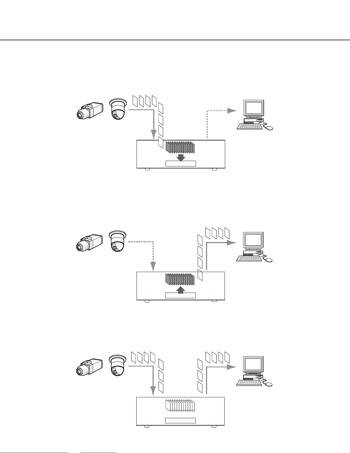
Recording/Playback/Live Image Transmission
Recording
Images will be transmitted from cameras to this unit and will be recorded. Images from up to 32 cameras can be
recorded on a single network disk recorder. Recorded images are compliant with the JPEG format.
It is possible to perform the settings relating recording such as resolution, recording rate, etc. on this unit.
Image data
Network camera
PC
HDD
This unit
Playback
Images recorded on the hard disk drive of this unit can be transmitted to a PC and they can be played. A single network disk recorder can transmit images to up to 8 PCs (web browsers). It is necessary to use a web browser or the
optional software (WV-AS65) to display recorded images.
Image data
Network camera
PC
HDD
This unit
Live Image Transmission
Live images from network cameras can be transmitted to PCs through this unit. Live images from up to 32 network
cameras can be transmitted to up to 8 PCs concurrently.
Image data
8
Network camera
PC
HDD
This unit
Page 9
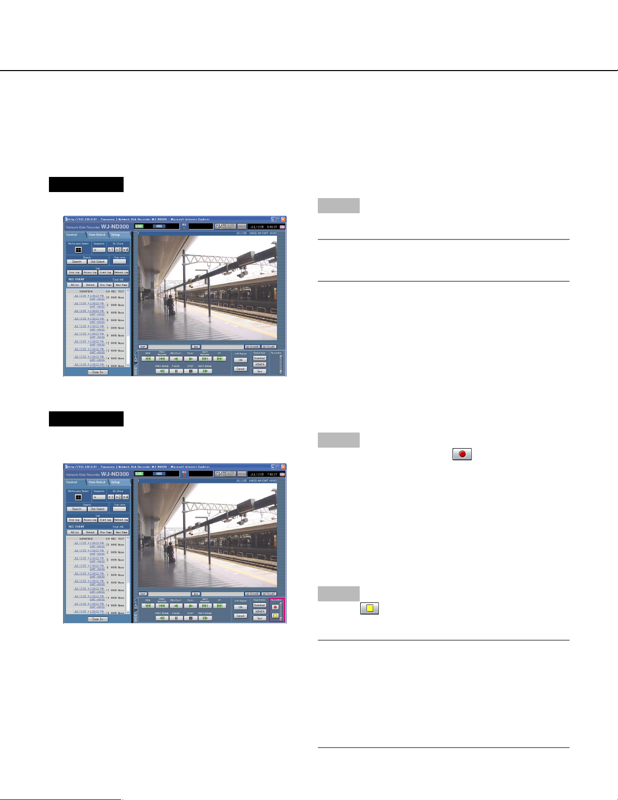
Recording
Start/stop recording manually.
Refer to a system administrator for the required settings for manual recording.
Refer to the Setup Instructions (PDF) for descriptions of how to turn on the unit and how to display the operation window.
Screenshot 1
Display the [HDD] tab.
Step 1
Click the [D] button of the [REC] box.
Note:
Hold down the [D] button until the [Recording] button and the [Stop recording] button are displayed.
Screenshot 2
The [Recording] button will be displayed in the [REC]
box.
Step 2
Start recording by clicking the [Recording] button.
• The REC indicator in the status display area will be
lit red when recording has started.
• When images from cameras are currently recorded
with higher priority than manual recording, manual
recording will be suspended until that recording finishes.
Refer to the following for further information about
each recording mode.
Step 3
Click the [Stop recording] button to stop recording.
→ The REC indicator will go off.
Notes:
• When stopping manual recording while another
recording with a different recording mode (ex. event
recording → next page) is being performed, the
[REC] indicator will remain lit and the other recording
will continue.
• It is impossible to record images when images are
not being received from cameras.
9
Page 10

About the recording mode and the priority
There are 5 recording modes. Each recording mode and priority is as follows.
When two or more recordings with different recording modes started simultaneously, only recording with the highest
priority will start.
Recording Mode
Emergency
recording
Post-event recording
Manual recording
Schedule recording
Pre-event recording
Description
When an emergency event occurs, perform recording manually using an
external switch, etc..
Perform recording manually at any event occurrence.
Start/stop recording manually.
It is possible to perform recording automatically at a schedule time on a
designated day of a week.
Perform recording manually at any event occurrence.
Priority
Highest
2
3
4
5
10
Page 11
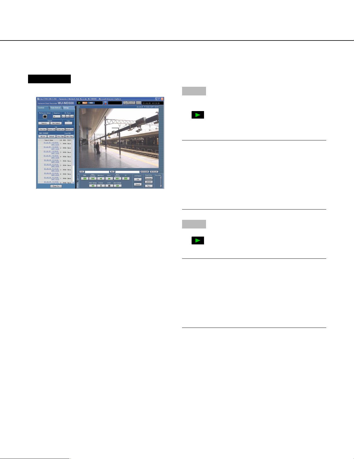
Playback
A recorded image can be played. Playback is also available during recording.
Screenshot 1
Display the [HDD] tab.
Step 1
Click the [PLAY] button.
→ Playback of a recorded image will be performed.
will be displayed in the status display area.
Playback will start from the finish point (time and
date) of the last playback.
Note:
When played for the first time after login, the latest
recorded image will be played. Playback will start 30
seconds before the time of the latest recorded image
with the default setting. The following are available
for the playback start time.
5 s/10 s/30 s/1 min/5 min
Refer to a system administrator for further information.
Step 2
Click the [STOP] button to stop playback.
→ displayed in the status display area will go off
and a live image will be displayed.
Note:
• It is possible to change camera channels by clicking
the desired camera channel on the [Cam Select] tab
during playback.
• It is possible to switch the screen to a quad-screen
by clicking the desired [Multiscreen Select] button
during playback.
• Clicking the camera title during quad display will display the clicked picture on a single screen.
11
Page 12
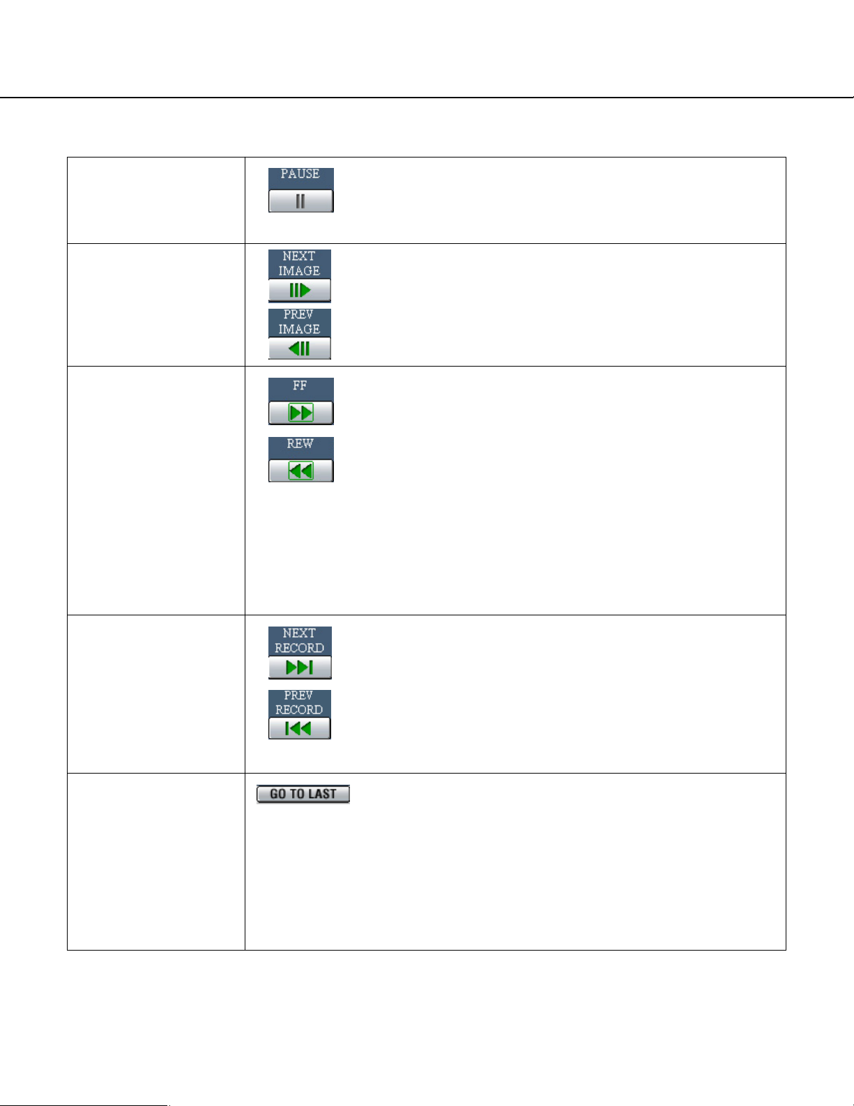
Other functions for playback
Pausing
Frame play/reverse
frame play
Fast playback/fast
reverse playback
• Playback will be stopped when this button is clicked during
playback.
• Playback will be resumed when this button is clicked during
pausing.
• Frame play/reverse frame play is available only during pausing.
• When the [NEXT IMAGE] button is clicked, the next frame is
played and paused.
• When the [PREV IMAGE] button is clicked, the previous frame
is played and paused.
• Playback speed will be changed in the following order each
time the fast playback button is clicked: Step2 (Approx. 4x) →
Step3 (Approx. 8x) → Step4 (Approx. 16x) →
Step5 (Approx. 32x) → Step6 (Approx. 48x) →
Step7 (Approx. 96x)
• Reverse playback speed will be changed in the following
order each time the fast reverse playback button is clicked:
Step2 (Approx. 4x) → Step3 (Approx. 8x) →
Step4 (Approx. 16x) → Step5 (Approx. 32x) →
Step6 (Approx. 48x) → Step7 (Approx. 96x)
• When the [PLAY] button or the [REV PLAY] button is clicked
during fast playback/fast reverse playback, playback speed
will return to the normal playback speed.
Skip/reverse skip
Skips to the latest
recorded image.
• When the [NEXT RECORD] button is clicked, playback is
skipped to the latest recorded image.
• When the [PREV RECORD] button is clicked, playback is
skipped to the oldest recorded image.
• When there is no latest/oldest recorded image to be skipped
to, the current playback will continue, but the playback may
start from a point around a minute before the last playback
point.
• Skips to the latest time of the image currently playing and
plays it. Skips to the point 30 seconds before the time of the
latest recorded image with the default setting.
The following points are available to be skipped to.
5 s/10 s/30 s/1 min/5 min
Refer to a system administrator for further information.
• When the [GO TO LAST] button is clicked while displaying live
images, playback of the latest recorded images from the
selected camera channel will start.
12
Page 13
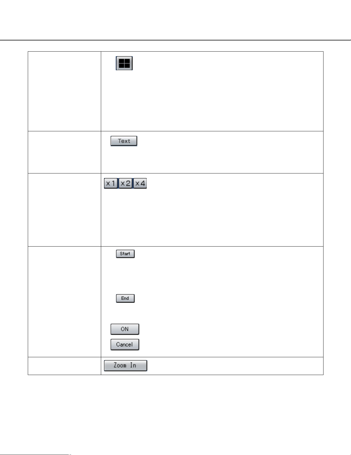
Playback on a multiscreen
• Displays playback images on a 4-Screen.
• Up to 4 camera images can be displayed simultaneously on a
4-Screen screen.
Images of the camera group (A-H) consisted from 4 camera
channels in advance will be switched and displayed sequentially on a 4-Screen screen.
Refer to the Setup Instructions (PDF) for descriptions of how
to perform the camera group settings.
• Click a camera title in the [Cam Select] tab or the camera title
displayed on the image to return to a single screen display.
Text
(page 31)
EL-Zoom
A-B Repeat Playback
• The attached text information will be displayed when this button is clicked during pausing.
Click the [Text] button after pausing playback.
• The text information display/edit is available only when a
recorded image is played in a single screen.
• Displayed playback images or live images will be enlarged.
• Click the button in the [EL-Zoom] box to zoom in on the dis-
played image.
[x1] button: Returns to the original displayed size (x1
zoomed size).
[x2] button: Displays images with x2 zoomed size.
[x4] button: Displays images with x4 zoomed size.
Clicking a point in the zoomed image moves the zoomed
image by positioning the clicked point as the center point.
Recorded images between two designated points (point A: start
point, point B: end point) will be played repeatedly.
q Designate a start point (A) by clicking the [Start] button during
playback.
→ The time and date of point A will be displayed next to the
[Start] button.
w Designate an end point (B) by clicking the [End] button during
playback.
→ The time and date of point B will be displayed next to the
[End] button.
e Playback between point A and B will start and keep playing
repeatedly when the [START] button is clicked.
r Click the [Cancel] button during A-B repeat playback to return
to normal playback.
Zoom In
Enlarges the live camera image and playback picture.
13
Page 14
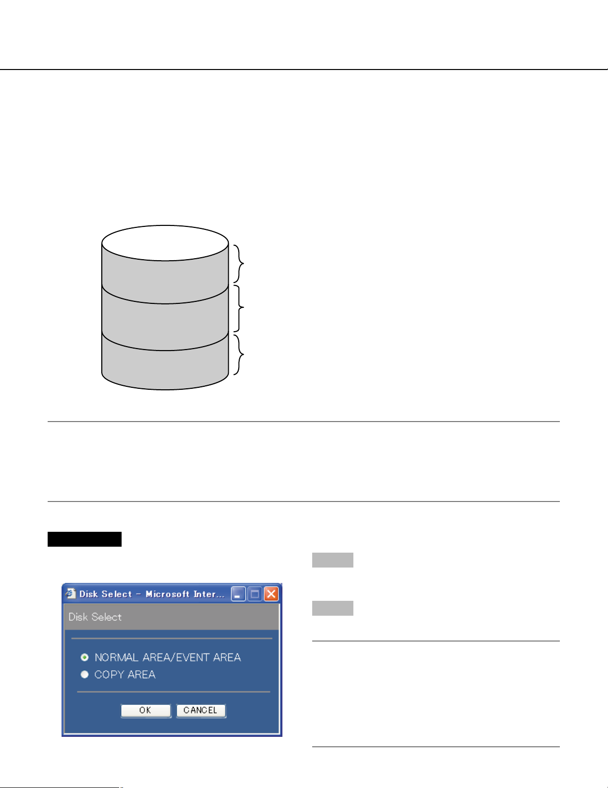
Playback after Selecting a Disk
Images from cameras will be recorded on the built-in hard disk drive of this unit.
Select a disk and play images as follows.
The following disks can be selected.
• HDD normal recording area/event recording area: Recording area in the built-in hard disk of this unit. Recorded
images by manual recording (page 9) or event recording will be stored in this area.
• HDD copy area: Copy area in the built-in hard disk of this unit. Recorded images will be copied in this area. (page
29)
Built-in hard disk (HDD)
Recording area for manual recording/normal recording
Normal recording area
Recording area for event recording
Event recording area
Recording area for copying
Copy area
Note:
• The built-in hard disk or the built-in hard disk in an extension unit is described as "disk" in these operating
instructions.
• Playback is also available during recording.
• The capacity of each recording area will be different depending on the settings. Refer to a system administrator
for further information.
Screenshot 1
Click the [Disk Select] button in the [Search] box of the
[Control] tab. The disk select window is displayed.
Step 1
Check the radio button of the desired disk to be played.
Step 2
Click the [OK] button.
14
Note:
It is impossible to select the HDD copy area in the
following cases (the pop-up window will be displayed):
• When the selected area has been selected by
another user
• When copying is being performed manually
• When playing images
Page 15
Screenshot 2
The selected disk will be displayed on the status display
area.
Screenshot 3
The [HDD] page will be displayed.
Step 3
Click the [HDD] tab.
Step 4
Click the [PLAY] button.
→ Recorded images on the selected disk will be
played. will be displayed in the status display
area.
Note:
Playback will start from the finishing point (time and
date) of the last playback by clicking the [PLAY] button after stopping playback.
Step 5
Click the [STOP] button to stop playback.
→ displayed in the status display area will go off
and a live image will be displayed.
15
Page 16
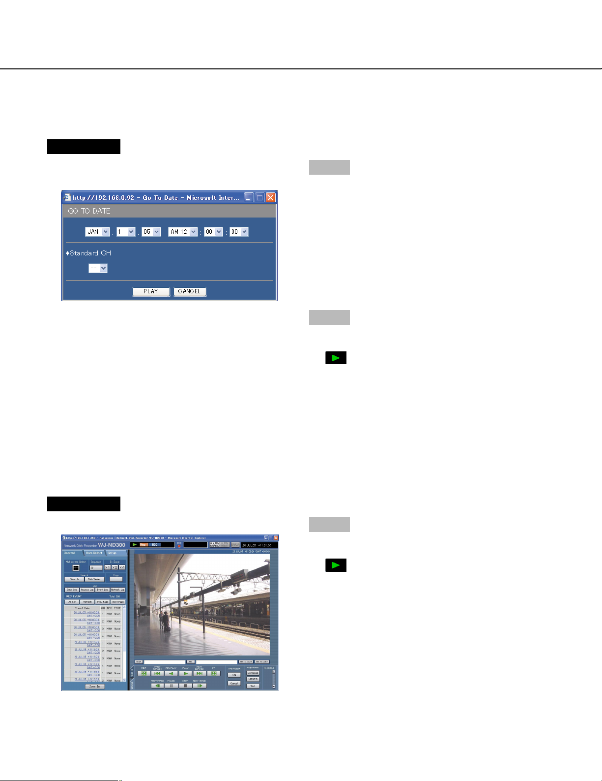
Playback from a Designated Time and Date
Start playback by designating the desired time and date of a recorded image to be played. Playback is also available
during recording.
Screenshot 1
Click the [GO TO DATE] button in the playback point
operation area to display the "GO TO DATE" window.
Step 1
Click the [i] button and enter the desired time and
date of a recorded image to be played.
• Search criteria (Camera CH)
Determine which camera channel is to be used as a
standard time zone when searching.
(It is necessary to determine the primary time and date
by selecting a camera channel when cameras are
installed in two or more countries.)
Step 2
Click the [PLAY] button.
→ Play recorded images of the entered time and date.
will be displayed in the status display area.
When there is no image for the entered time and
date, the following action will be taken.
When there are images recorded after the entered
time and date, the nearest recorded image after the
entered time and date will be played.
When there are images recorded after the entered
time and date, the nearest recorded image after the
entered time and date will be played.
Screenshot 2
The recorded images will be played in this area.
16
Step 3
Click the [STOP] button on the [HDD] tab to stop playback.
→ displayed in the status display area will go off
and a live image will be displayed.
Page 17
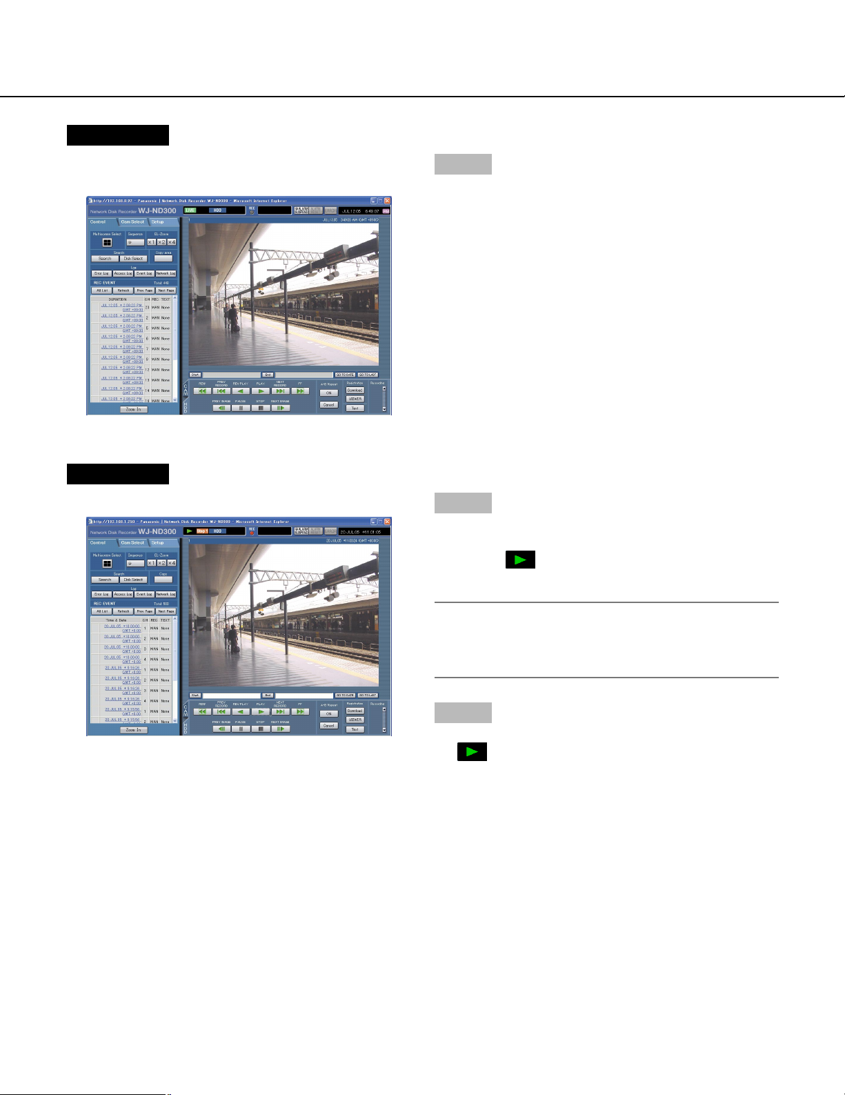
Search and Play Recorded Event
Search for a recording event and play it (recording event search)
Recording events can be searched by filtering as follows.
Note:
Area of the hard disk drive subject to search for recording events is different depending on the disk area. To
search for recording events in the HDD normal recording area and event recording are, select "NORMAL
AREA???" or "EVENT AREA???". To search for recorded images in the copy area, select "COPY AREA???".
Refer to page 14 for further information about "DISK SELECT".
About Filtering
Conditions for filtering How to search
Time and date Designate a time period and search images recorded in the designated period to
play.
Event Searches for images from the selected recording mode only. The following recording
modes can be selected.
• Manual: Manual recording (page 9)
• Schedule: Schedule recording (Operating Instructions (PDF))
• Emergency: Emergency recording (Operating Instructions (PDF))
• Pre: Pre-event recording (page 27)
• Site alarm: Recording at a site alarm occurrence (page 26)
• Terminal alarm: Recording at a terminal alarm occurrence (page 26)
• Command alarm: Recording at a command alarm occurrence (page 26)
Text Searches only images recorded with/without text information.
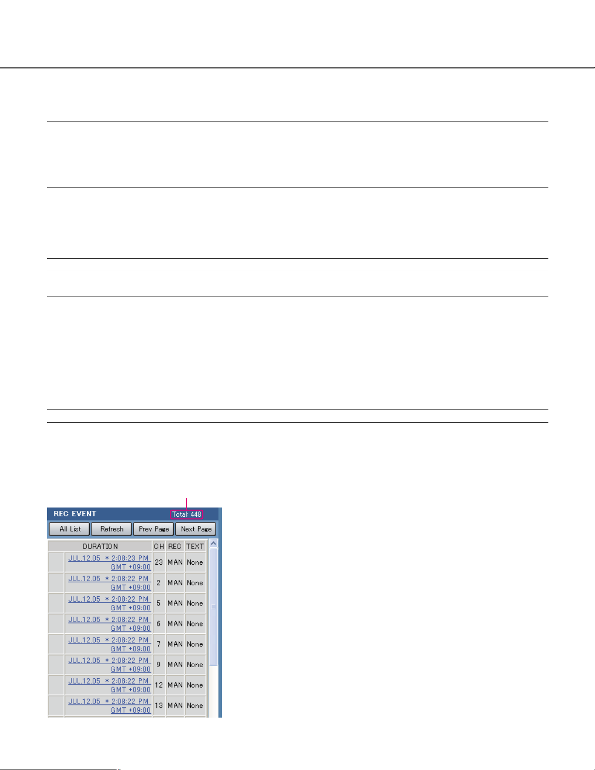
About Displaying the Recording Event List Window
Number of the listed data
Number of the listed data: Displays the total number
of the listed data
[All List] button: Cancels filtering and lists all recording
events.
[Refresh] button: Refreshes the displayed contents to
the newest one.
[Prev Page] button: Displays the previous page of the
list.
[Next page] button: Displays the next page of the list.
DURATION: Start time of recording will be displayed.
CH: A camera channel currently used for recording will
be displayed. Recorded images of the displayed
camera channel will be played in a single screen.
REC: Recording mode will be displayed.
MAN: Manual Recording
SCH: Schedule recording
EMR: Emergency recording
TRM: Recording at a terminal alarm occurrence
COM: Recording at a command alarm occurrence
17
Page 18

How to Operate
Screenshot 1
Click the [Search] button in the [Search] box of the
[Control] tab. The REC event search window is displayed.
CAM: Site alarm
PRE: Pre-event recording
Text: When text information is attached to the recorded
image, "Added" will be displayed. When text information is not attached to the recorded image,
"None" will be displayed.
Step 1
Select searching conditions
• Time & Date
Filter by time and dateSelect a start time and an end
time by clicking the [i] button.
• REC Events
Filter by recording event. Click to select the desired
recording event to be displayed when filtering by recording events.
• Search CH
Determine which camera channel is to be used as a
standard time zone when searching.
(It is necessary to determine the primary time and date
by selecting a camera channel when cameras are
installed in two or more countries.)
• Camera
Filter by camera channel. Check the radio button of the
desired camera channel to be searched for.
• Text
Filter by with/without text informationSelect "Added" or
"None" by clicking the [i] button.
When "--" is selected, searching will be performed without filtering by with/without text information.
18
Step 2
Click the [OK] button.
→ will be displayed in the status display area.
The filtered result will be displayed.
Note:
Click the [All List] button to cancel the filtering.
will go off and all recording events will be
listed.
Page 19

Screenshot 2
The search results (recording event list) will be displayed below the [Control] tab.
Step 3
Click the time of the desired recording event.
→ Play a recorded image of the recording event from
the selected time.
Step 4
Click the [STOP] button to stop playback.
19
Page 20

Monitor Live Images
Live image will be displayed in the web browser window.
It is possible to display live images on a single screen or a multi-screen in the web browser window.
It is also possible to display live images sequentially (sequential display).
Display Images from a Camera on a Single Screen
Screenshot 1
Display the [Cam Select] tab.
Step 1
Click the desired camera title from the list displayed in
the [Cam Select] box.
Screenshot 2
Live images from the selected camera channel will be
displayed.
Notes:
• Camera Select
Clicking the camera title will display a list of cameras
connected to the unit.
Images from the selected camera channel will be
displayed on the image display area by clicking one
of camera names.
• About the electrical zoom
When displaying an image on a single screen,
zooming in on the displayed image is possible.
Click the button in the [EL-Zoom] box to zoom in on
the displayed image.
[x1] button: Returns to the original displayed size
(x1 zoomed size).
[x2] button: Displays images with x2 zoomed size.
[x4] button: Displays images with x4 zoomed size.
Clicking a point in the zoomed image moves the
zoomed image by positioning the clicked point as
the center point.
• When the [GO TO LAST] button is clicked while displaying live images, playback of the latest recorded
images from the selected camera channel will start.
20
Page 21

Display Images from Cameras on a 4-Screen
Images from cameras will be displayed on a 4-Screen screen.
Screenshot 1
Display the [Camera Select] tab.
Step 1
Click the button of the [Multiscreen] box.
Screenshot 2
Images from cameras will be displayed on a 4-Screen
screen.
Step 2
Up to 4 camera images can be displayed simultaneously on a 4-Screen screen.
Each time the button is clicked, the camera picture is
changed to quad display according to the settings made
in [Advanced] – [System] – [Basic Setup] – [Monitor
Display Setup] of the setup menu.
Step 3
Click a camera title in the [Cam Select] tab or the camera title displayed on the image to return to a single
screen display.
Note:
When the [GO TO LAST] button is clicked while displaying live images, playback of the latest recorded
images from the selected camera channel will start.
21
Page 22

Display Images in the Sequential Display
Displayed images from cameras will be switched automatically.
Camera images will be displayed sequentially according to the settings performed in advance.
Screenshot 1
Display the [Cam Select] tab.
Step 1
Click the button of the [Sequence] box.
→ The lamp on the button lights (green) during
sequence operation.
The sequence action will start and the lamp on the
button will light (green) during sequence operation.
The "SEQ" indication will also light on the status display area.
Screenshot 2
Live images will be displayed sequentially according to
the settings performed in advance.
Step 2
To stop the sequential display, click the button once
again. The lamp on the button will go off when
sequence operation is stopped.
When operations to display images on a single screen
(page 20) or 4-Screen screen (page 21) are performed
during the sequential display, the sequential display will
be canceled.
Note:
• The sequence step that is unavailable to display will
be skipped.
• When the [GO TO LAST] button is clicked while displaying live images, playback of the latest recorded
images from the selected camera channel will start.
22
Page 23

Control Cameras
When displaying live images, the following camera controls are possible.
• Panning/tilting: Moves a camera horizontally/vertically.
• Zooming: Zooms in/out of images.
• Focus: Adjusts the focus.
• Iris: Adjusts the iris of the lens.
• Preset action: Moves a camera to the preset position registered in advance.
• Auto: Moves a camera with an auto function set in advance.
Note:
• Depending on the models of the connected cameras, it may be impossible to control the camera or some functions may be not available.
• Controlling cameras is possible only when displaying live images on a single screen.
Panning/Tilting Operation
Moves a camera horizontally/vertically.
Screenshot 1
Display the [CAM] tab.
Step 1
Moves a camera horizontally/vertically in the following
ways.
• Control buttons: Click to move the camera.
• Control pad: Click to move the camera. Panning/tilt-
ing speed will be faster if a clicked point gets farther
from the center point of the control pad.
• Image display area: Click the desired point to be the
center of the field angle in the displayed image.
The camera moves to position the clicked point as
the center point of its image.
Control buttons/Control pad
Image display area
23
Page 24

Zoom/Focus/Iris Operations
Zooming: Zooms in/out of images. Depending on the models of the connected cameras, the image size for the
respective zooming portion may be different. For further information, refer to the operating instructions of the
camera.
Focus adjustment: Adjusts the focus. The auto focus function is available.
Iris adjustment: Adjusts the iris of the lens. Adjusts the iris of the lens.
Screenshot 1
Display the [CAM] tab.
Step 1
• Zooming
Adjust zooming by clicking the [Wide] button or the
[Tele] button in the [Zoom] box.
• Focus adjustment
Adjust the focus by clicking the [Near] button or the [Far]
button in the [Focus] box.
The auto focus function is available by clicking the
[Auto] button.
• Iris adjustment
Adjust the iris by clicking the [Open] button or the
[Close] button in the [Iris] box.
Click the [Reset] button to reset the setting for the iris.
24
Page 25

Move a Camera to the Preset Position
Moves a camera to the preset position registered in advance. Registering preset positions is required to perform the
preset function.
Refer to the operating instructions of the connected camera for the descriptions of how to register the preset position. It is impossible to register the preset positions of cameras using this unit.
Screenshot 1
Display the [CAM] tab.
Step 1
Click the [i] button in the [Preset] box to select a preset number (HOME, 1 - 16) to be moved.
Step 2
Click the [Set] button.
→ The camera moves to the registered preset position
respective to the selected preset number.
Auto Function (Auto Pan, etc)
Moves a camera with an auto function set in advance.
Screenshot 1
Display the [CAM] tab.
Step 1
The auto function can be performed by clicking the [ON]
button in the [Auto] box.
Click the [OFF] button to stop the auto function.
Note:
Refer to the operating instructions of the connected
camera for further information about the auto function of the camera.
25
Page 26

About the Event Function
The event action will be performed when the following events occur.
• Terminal alarm: When a signal is supplied from an external device such as a door sensor to the ALARM
terminal, this is stated as an event of a terminal alarm.
• Command alarm: A command alarm is sent from a PC via a network.
• Site alarm: An alarm using Panasonic Protocol is sent from a network camera.
Action at an Event Occurrence
The event action will be performed according to the settings when an event occurs.
There are 3 event action modes for the alarm mode (ALM), the activity mode (ADM) and OFF for each event type.
The event action will be different according to the set event action mode.
About the event action mode
• Alarm Mode (ALM)
This mode notifies of an event occurrence outside. Action taken in the alarm mode is referred to as the alarm
action.
• Activity Detection Mode (ADM)
This mode does not notify of an event occurrence outside, but records event log and performs preset actions.
• OFF
Performs only recording of the event log. Other event actions will not be performed.
Alarm action Alarm Mode Activity mode OFF
Start recording.
Alarm message.
Blinks the alarm indicator.
Sounds the buzzer.
Move a camera to the preset position
Notifies of an event occurrence by sending e-mails.
Supplies a signal from the ALARM connector or the
ALARM/CONTROL connector on the rear panel of this unit
(Alarm signal output).
Record the event log.
Transmits images onto an FTP server
Notifies of an alarm occurrence according to the Panasonic
protocol settings.
✓: Applicable –: Not applicable
✓
✓
✓
✓
✓
✓
✓
✓
✓
✓
✓
–
–
–
✓
–
–
✓
–
–
–
–
–
–
–
–
–
✓
–
–
26
Page 27

About the alarm action
• Start recording.
Recording will start at an event occurrence. Recording will be performed according to the settings such as
recording duration, recording rate, etc. that were configured on the setup menu. (Refer to the Setup Instructions
(PDF) for further information.)
Depending on the settings, it is possible to start recording images before an event occurs (Pre-event recording).
• Displays alarm message.
The pop-up window that notifies of an event occurrence will be displayed at an event occurrence.
• Blinks the alarm indicator.
The alarm indicator on the front panel of the unit will start blinking at an event occurrence.
• Sounds the buzzer.
The buzzer will start sounding for the set duration according to the settings configured on the setup menu. (Refer
to the Setup Instructions (PDF) for further information.) When the buzzer settings are not configured, the buzzer
will not sound.
• Move a camera to the preset position
The camera will move to the preset position registered in advance at an event occurrence. Refer to the operating
instructions of the connected camera for the descriptions of how to register the preset position.
• Notifies of an event occurrence by sending e-mails.
When an event occurs, this unit notifies of the event occurrence with the time and date of the event occurrence
by sending e-mails (alarm mails) to the registered addresses. It is also possible to attach an image to the alarm
mail.
Up to 4 addresses can be registered as recipients of the alarm mail.
To send the alarm mail at an event occurrence, it is required to perform the settings on the SETUP MENU in
advance.
• Supplies a signal from the ALARM connector or the ALARM/CONTROL connector on the rear panel of
this unit (Alarm signal output).
It is possible to output signals from the ALARM connector on the rear panel of the unit and sound the buzzer
when an event occurs. The alarm output duration can be set on the setup menu. (Refer to the Setup Instructions
(PDF) for further information.)
• Record event log.
The event type and the occurrence time and date will be recorded when an event occurs.
• Transmits recorded images to an FTP server at an event occurrence
When an event occurs, recorded images will be continued transmitting to an FTP server automatically for the set
duration from the recording start time. To send the alarm image to an FTP server at an event occurrence, it is
required to perform the settings on the SETUP MENU in advance. Refer to the Setup Instructions (PDF) for further information.
• Notifies a PC of an alarm occurrence according to the Panasonic protocol settings.
Select "ON" or "OFF" to determine whether or not to notify of an alarm occurrence (or error information) to a PC
according to the "Network Panasonic Protocol" of the setup menu ("Comm" – "Network Panasonic Protocol").
To receive a notification (or error information) and display the contents of the notification, the optional software
(WV-AS65) is necessary.
27
Page 28

28
Cancel the Alarm Action
The alarm action will be performed when an event is detected.
To cancel the alarm action manually, do the following.
Screenshot 1
[ALARM RESET] will be displayed in the status display
area when an alarm occurs.
Step 1
Click the [ALARM RESET] button.
→ The alarm action will be canceled.
Suspend the Alarm Action
Configure the settings to not to perform the alarm action even when an event occurs. It is useful to suspend the
alarm action at an event occurrence such when maintaining the unit for a certain period.
Even though the alarm action is suspended, recording of images, event log recording and the preset action will be
performed.
Screenshot 1
The operating window will be displayed.
Step 1
Click the [ALARM SUSPEND] button.
→ The alarm action will be suspended.
The "ALARM SUSPEND" indicator on the front panel of
the unit will light.
Step 2
To release the alarm suspension, click the [ALARM
SUSPEND] button again.
→ The "ALARM SUSPEND" indicator on the front panel
of the unit will go off.
Page 29

Copying (Duplicate)
Images recorded on the normal area/event area can be copied manually onto the copy area of the hard disk drive.
It is recommended to make back-up copies on a regular basis for unexpected situations such as malfunction of the
hard disk.
Manual copy is available during the following.
• While displaying live images
• While playback or pausing playback of recorded images
Screenshot 1
Display the [Control] tab.
Step 1
Click a button in the [Copy] box of the [Control] tab.
Note:
It is impossible to copy recorded images in the following cases.
(The pop-up window will be displayed when the button in the [COPY] box is clicked.)
• When copying is being performed
• When a download is being performed (page 37)
• When "COPY AREA" is selected for "DISK
SELECT"
Screenshot 2
The data copy window will be displayed.
Step 3
Select a start time and an end time for copying by clicking the [i] button.
Step 4
Determine which camera channel is to be used as a
standard time zone when searching.
(It is necessary to determine the primary time and date
by selecting a camera channel when cameras are
installed in two or more countries.)
Step 5
Click the [OK] button.
→ will be displayed in the status display area
when copying starts. However, copying will not be
performed in the following cases (the pop-up window
will be displayed):
• When another user has selected the desired
copy drive
• When copying is being performed
Step 2
Click to select the desired camera channel to be copied.
It is possible to select two or more camera channels.
Note:
It is possible to cancel copying using the copy cancel window that can be displayed by clicking the
[COPY] button during copying.
29
Page 30

Deletion of Recorded Images Saved on the Hard Disk Manually
Delete recorded images saved in the normal area, the event area or the copy area of the hard disk manually.
By setting a time and date, the images recorded the day before the set time and date will be subject to deletion.
Important:
• It is impossible to recover the deleted images.
• It is possible to delete recorded images automatically when the set days have passed from the day the image
was recorded (HDD auto deletion).
Refer to a system administrator for further information.
• When "STOP" is selected for "Disk End Mode" of "Maintenance", the available disk space will not be increased
even though deletion is performed.
Screenshot 1
Click the [Maintenance] button in the setup menu
(Advanced) and then click "Data Delete". The "Data
Delete" window will be displayed.
Step 1
Set time and date for any of "Manual Delete for Normal
Recording Area", "Manual Delete for Event Recording
Area" or "Manual Delete for Copy Area" by clicking [i].
Images recoded before the set time and date will be
deleted.
Screenshot 2
The confirmation window will be displayed.
Step 2
Click the [DELETE] button.
Step 3
Click the [OK] button.
→ Start deletion. When deletion complete, the "Data
Delete" window will be operable again.
30
Page 31

Display/Edit the Text Information
It is possible to attach text information to images when recording.
It is possible to enter up to 200 characters for text information.
These are the descriptions of how to display/edit the attached text information to images.
Note:
Displaying/editing text information is possible during pausing playback on a single screen.
Screenshot 1
Start operation after starting playback of recorded
images in a single screen.
Step 1
Pause playback by clicking the [Pause] button.
Step 2
Click the [Text] button in the [HDD] tab.
Screenshot 2
The "Edit Text" window will be displayed.
Step 3
The text information attached to the recorded images
will be displayed.
Step 4
Edit text information. It is possible to enter up to 200
characters (up to 10 lines) for text information.
• About the available characters
The following alphanumeric characters can be entered.
A B C D E F G H I J K L M N O P Q R S T U V W X Y Z
a b c d e f g h i j k l m n o p q r s t u v w x y z 0 1 2 3 4 5
6 7 8 9 ! " # $ % & ' ( ) * + , - . /: ; < = > ? @ [ \ ] ^ _ ` | } ~
(space)
Step 5
Click the [SET] button.
→ The text information will be registered.
Step 6
Click the [Close] button.
→ The [Edit Text] window will close.
31
Page 32

Transmits Camera Images onto an FTP Server
It is possible to transmit images to an FTP server.
Image transmission can be performed at a designated time periodically (FTP SEND BY PERIODIC TIMER) or at an
event occurrence (FTP ALARM SENDING).
Transmit Images from Cameras Periodically
It is necessary to perform the settings on the setup menu in advance to transmit images from cameras to an FTP
server periodically.
The settings relating to "FTP SEND BY PERIODIC TIMER" such as FTP server directory, transmission interval,
source camera channel, etc. can be performed on the setup menu (Advanced) ("Comm" - "Network FTP Setup" "FTP SEND BY PERIODIC TIMER").
Select "ON" or "OFF" on the setup menu (Advanced) ("Schedule" - "Time Table" - "FTP SEND PERIODIC TIMER")
whether or not to transmit images periodically.
Refer to the Setup Instructions (PDF) for setup.
Transmit Images from Cameras at an Event Occurrence
It is necessary to perform the settings on the setup menu in advance to transmit images from cameras to an FTP
server at an event occurrence.
The settings relating to "FTP ALARM SENDING" such as FTP server name, "Duration-Pre", "Duration-Post", etc.
can be performed on the setup menu (Advanced) ("Comm" - "Network FTP Setup" - "FTP ALARM SENDING").
Select "ON" or "OFF" on the setup menu (Advanced) ("Schedule" - "Time Table" - "FTP ALARM SENDING")
whether or not to transmit images at an event occurrence.
Refer to the Setup Instructions (PDF) for setup.
32
Page 33

Check Logs
The following logs can be checked.
• Error log
• Access log
• Event log (event occurrence time and details)
• Network trouble log
Check the Error Log
The error log will be displayed in list form.
Screenshot 1
Display the [Control] tab.
Step 1
Click the [Error Log] button in the [Log] box of the
[Control] tab.
Screenshot 2
The error log (the error log window) will be displayed in
list form below the [Control] tab. Refer to page 47 for
further information about the error log.
Step 2
Click the [List] button to close the error log window.
Note:
• Up to 100 error logs can be kept. When more than
100 event logs are filed, the older event logs will be
overwritten by the newer event logs.
• In this case, the oldest log is the first to be overwritten.
33
Page 34

Check the Access Log
The time when logged in/out for this unit, the user name, and the IP address will be displayed.
Screenshot 1
Display the [Control] tab.
Step 1
Click the [Access Log] button in the [Log] box of the
[Control] tab.
Screenshot 2
The access log (the access log window) will be displayed in list form below the [Control] tab.
Indications for access log
**IN: The user name or the IP address displayed before
IN indicates the user/host logged in.
**OUT: The user name or the IP address displayed
before OUT indicates the user/host logged out.
A user name or IP address will be displayed.
Step 2
Click the [List] button to close the access log window.
Note:
Up to 100 access logs can be kept.
When more than 100 event logs are filed, the older
event logs will be overwritten by the newer event
logs.
34
Page 35

Check the Event Log
The event logs (event occurrence times and their details) will be displayed.
Refer to page 26 for further information about each event.
Screenshot 1
Display the [Control] tab.
Step 1
Click the [Event Log] button in the [Log] box of the
[Control] tab.
Screenshot 2
The event log (the event log window) will be displayed
in list form below the [Control] tab.
Indications for event log
COM: Command alarm
EMR: Emergency recording
TRM: Terminal alarm
CAM: Site alarm
Step 2
Click the [List] button to close the event log window.
Note:
Up to 750 event logs can be kept.
When more than 750 event logs are filed, the older
event logs will be overwritten by the newer event
logs.
35
Page 36

Check the Network Trouble Log
The network log (network event) will be displayed in list form.
Screenshot 1
Display the [Control] tab.
Step 1
Click the [Net Log] button in the [Log] box of the
[Control] tab.
Screenshot 2
The network trouble log (the NW log window) will be displayed in list form below the [Control] tab. Refer to page
47 for further information about the network trouble log.
Step 2
Click the [List] button to close the NW log window.
Note:
• Up to 1 000 network trouble logs can be kept. When
more than 1 000 event logs are filed, the older event
logs will be overwritten by the newer event logs.
• When the same trouble as the one recorded on the
latest log occurred, only the latest log will be updated.
36
Page 37

Download Recorded Images
Designate the start point and the end point of played images and download images to a PC.
Recorded images will be downloaded as image data files (filename.n3r). Refer to page 39 for the descriptions of how
to play the downloaded images.
Important:
• When downloading, the available disk space must be 2 or more times the size of the file to be downloaded.
* It is a feature of Internet Explorer.
• Otherwise, it may be impossible to properly play the downloaded file on a PC.
Screenshot 1
Display the [HDD] tab.
Step 1
Enter the desired start time for download in the [Start]
box on the playback point operation area.
It is also possible to designate the start time by clicking
the [Start] button at the desired point to set as the start
point of the image to be downloaded.
→ The time and date of the start point will be displayed
in the playback position display area.
Screenshot 2
The "DOWNLOAD SETUP" pop-up window will be displayed.
Step 2
Enter the desired end time for download in the [End]
box on the playback point operation area.
It is also possible to designate the end time by clicking
the [End] button at the desired point to set as the end
point of the image to be downloaded.
→ The time and date of the end point will be displayed
in the playback position display area. It is possible to
designate up to 20 minutes of the time range per
download.
Step 3
Click the [Download] button.
Step 4
Click the [OK] button after selecting "ON" or OFF" for
"Alter Detect" to determine whether or not to attach an
alteration detection code to recorded images to be
downloaded.
Note:
The download time will be longer when "ON" is
selected for "Alter Detect".
37
Page 38

Screenshot 3
The download window will be displayed.
Screenshot 4
The "Save as…" window will be displayed.
Step 5
Click the [Save] button.
Step 6
Create a new folder in the desired directory and click
the [Save] button.
→ Recorded images will be downloaded as image data
files (filename.n3r).
38
Page 39

Play Downloaded Images
Recorded images will be downloaded as image data files (filename.h3r). It is possible to play, save and print downloaded images using the viewer software on the provided CD-ROM (Downloading this software is also available.)
Download the Viewer Software
Screenshot 1
Display the [HDD] tab.
Step 1
Click the [VIEWER] button of the [Registration] box.
Screenshot 2
The download window will be displayed.
Screenshot 3
The "Save as…" window will be displayed.
Step 2
Click the [Save] button.
Step 3
Create a new folder in the desired directory and click
the [Save] button.
→ The viewer software (filename.n3r) will be down-
loaded.
39
Page 40

Playback Downloaded Images
Screenshot 1
Start up the viewer software and display the following
window.
Screenshot 2
The [Open file] window will be displayed.
Step 1
Click the [OPEN] button.
Step 2
Select the downloaded image data file (filename.n3r).
Screenshot 3
The recorded images will be played in this area.
Step 3
Click the [Open] button.
Step 4
Click the [PLAY] button.
40
Page 41

Save Downloaded Images
It is possible to save the paused image as a bitmap file (extension: bmp) or a jpeg file (extension: jpg). Saving the
downloaded file is available only when the image is paused.
Screenshot 1
Start operation when playing the downloaded images
using the viewer software.
Step 1
Click the [PAUSE] button.
Step 2
Click the [SAVE] button.
Screenshot 2
The "Save as…" window will be displayed.
Step 3
Enter the file name and select the file format (BMP or
JPG/JPEG).
Step 4
Designate the folder and click the [Save] button.
→ The image data will be downloaded and saved.
41
Page 42

Print the Displayed Image
It is possible to print the paused image.
Screenshot 1
Start operation when playing the downloaded images
using the viewer software.
Step 1
Click the [PAUSE] button.
Step 2
Click the [PRINT] button.
Note:
The time and date being displayed on the viewer
when paused will also be printed.
42
Page 43

Perform the Alteration Detection
It is possible to detect the alteration of the data if a code for the alteration detection has been attached to the downloaded data. Refer to page 37 for descriptions of how to attach a code for the alteration detection.
Screenshot 1
Start up the viewer software and display the following
window.
Screenshot 2
The [Open file] window will be displayed.
Step 1
Click the [OPEN] button.
Step 2
Select the downloaded image data file (filename.n3r).
Screenshot 3
The first frame of the downloaded image will be displayed and paused.
Step 3
Click the [Open] button.
Step 4
Click the [ALT CHECK] button.
→ The alteration detection will start.
The following pop-up window will be displayed
while/after performing the alteration detection.
OK (Not Altered): No alteration was detected.
NG (Altered): Alteration was detected.
Note:
The [ALT CHECK] button will be displayed only
when opening an image data file with a code for the
alteration detection.
43
Page 44

Notification by E-Mail
Alarm Mail Notification
The following mail will be sent to notify of an alarm occurrence to a registered address when an alarm occurs.
Contents of the alarm mail:
In ND300 (192.168.0.250), alarm was occurred.
Alarm date: xx-xxx-xxxx xx:xx:xx GMT xx:xx (Example: 1-JAN-2005 12:00:00 AM)
Cause of alarm: Displays an event type and a camera channel or an alarm number (Example: Command 5CH)
File name of alarm image: The file name of the image attached to an e-mail.
URL: http://192.168.0.250/
Edit the Contents of the Alarm Mail
It is possible to edit the contents of the alarm mail that notifies of the event occurrence with the time and date of the
event occurrence.
To edit the alarm mail, do the following.
Step 1
Edit the contents using text editing software and save in the text format.
Depending on the item (time and date at an event occurrence, cause of alarm, host address, etc.) to be displayed,
the characters to be entered will be different. Refer to the following list of characters to be replaced when editing the
contents of the mail. Save the edited mail contents with the file name "almmail.tmpl".
Step 2
Start up the FTP software and enter the IP address of the unit to connect to that unit.
Enter the user name and password as follows.
User Name: User ID of the administrator (Default: ADMIN)
Password: Password respective to the user ID of the administrator (The default password is 12345.)
Refer to a system administrator for further information about the settings of user name and password.
Step 3
Transfer the edited file (almmail.tmpl) in the text format.
The directory to be sent is as follows.
/user/ND300/HTML_FILES
44
Page 45

List of characters to be replaced
Item to be displayed Display style of Example
entered characters
Time and date when the alarm occurred %#05000000 4-digit display (2003 - 2099)
Month when the alarm occurred (number) %#05000100 1 or 2-digit display (1 - 12)
Month when the alarm occurred (letters) %#05000200 Displays first 3 letters (Jan, Feb … Dec)
Day when the alarm occurred %#05000300 1 or 2-digit display (1 - 31)
Time when the alarm occurred %#05000400 24-hour display (15:00:00)
Mail address of the sender %#05000500
Host name of ND300 %#05000600
IP Address of ND300 %#05000700 192.168.0.250
Cause of alarm %#05000800 Terminal: Terminal, Command: Command
Emergency recording: Emergency
Site: Camera
Alarm number %#05000900 1 or 2-digit (1 - 32) + CH
File name of the alarm image %#05001000 xx_ALMyyyynnddhhmmss.jpg
Remains blank when no alarm image exists.
xx: Camera channel number
yyyymmdd: Date (year, month, day) when the
alarm occurred
hhmmss: Time (hour, minute, second) when the
alarm occurred
URL %#05001100 Host name/domain name: HTTP port number/
• When "Host Name" and "Domain Name" are
set (Only when "OFF" is selected for "DDNS")
• When the host name and the domain name
are obtained correctly using DDNS (Only when
"ON" is selected for "DDNS")
IP Address: HTTP port number/
• When "Host Name" and "Domain Name" are
not set (Only when "OFF" is selected for
"DDNS")
• When the host name and the domain name
failed to be obtained correctly using DDNS
(Only when "ON" is selected for "DDNS")
The part following the IP address (:"HTTP port
number) will be omitted when "80" is set for
"HTTP Port Number".
45
Page 46

Warning Mail Notification
The following mail will be sent to notify of a trouble occurrence to a registered address when the trouble occurs.
ND300 (192.168.0.250) STATUS REPORT.
Time and date: 2005-1-1 12:00:00
STATUS: The description of the trouble will be displayed. (Ex. THERMAL ERROR)
Display Description
DATE Time and date when the trouble occurred will be displayed.
STATUS The description of the trouble will be displayed.
HDD Capacity warning*1: <except FULL>
EVENT-HDD CAPACITY REMAINS ** %
COPY-HDD CAPACITY REMAINS ** %
** indicates the available disk space (%)
<FULL>
EVENT-HDD FULL
COPY-HDD FULL
Power outage detection: POWER LOSS
Recover from a power outage: POWER RECOVERD
NW camera trouble detection: CAM**COMMUNICATION ERROR
HDD smart warning: HDDx-y DISK WARNING
x-y indicates disk number (sequential serial number)
HDD hour meter warning: HDDx-y HOUR METER WARNING
Remove auto links: HDDx-y LOGICALLY REMOVED
x-y indicates disk number (sequential serial number)
RAID5 recovery failure: HDDxRAID5 RECOVERY FAILURE
(X indicates unit number, Y indicates disk number)
Fan trouble: FAN ERROR x-y
X indicates unit number, Y indicates fan number
Thermal trouble: THERMAL ERROR x-y
X indicates unit number, Y indicates sensor number
NW Link error???: PORTx NETWORK LINK ERROR
x indicates network port number
RAID1 down: HDDx-y RAID5 1DOWN
x-y indicates disk number (sequential serial number)
RAID2 down: HDDx-y RAID5 2DOWN
x-y indicates disk number (sequential serial number)
DHCP IP address lost: PORTx DHCP ERROR
x indicates network port number
HDD capacity warning
A warning mail with the <except FULL> content will be sent when the available disk space becomes less than the
set value for "Capacity warning" in the "Maintenance" menu. After a warning mail is sent, a warning mail with the
<except FULL> content will be sent each time 1% of the available disk space is reduced, and a warning mail with the
<FULL> content will be sent when there is no available disk space.
46
Page 47

About the Error Log
The following are the descriptions about the contents of the error log and the network error log.
Content
Power outage
detection
Recover from a
power outage
Fan warning FAN u-f – FAN-0-u-f ERR
Thermal error
warning
Extension mode
settings error
HDD Write error W-ERR u-d –––
HDD Read error R-ERR u-d –––
RAID 1 down HDu-d 1DOWN ––HDD error output
RAID 2 down HDu 2DOWN ––HDD error output
Disk array change ––
HDD S.M.A.R.T.
warning
HDD hour meter
warning
Remove auto
links
HDD RAID5 R-FAIL u – HDD-4-u ERR
EVENT area
available capacity
warning
EVENT area
available capacity
warning (FULL)
COPY area
available capacity
warning
COPY area
available capacity
warning (FULL)
HDD RAID board
initialization
failure
Network link error
Copy error
Error Log Network log Indication on
the LED
PWR LOSS – SYS-1 ERR
POWER FAILURE
PWR RECOVER –––
FAN ERROR
THERMAL u-0 – TML-1-u-1 ERR
THERMAL ERROR
–– SYS-2 SINGLE
MIX ERROR
Please Setup on
DISK CONFIG MENU
SMART u-d – HDD-1-u-d ERR
HDD WARNING
H.METER u-d – HDD-2-u-d ERR
HDD HOUR METER
REMOVE u-d – HDD-3-u ERR
HDD REMOVED
RAID5 RECOVERY
–– –Copy/event recording
*-FULL – HDD-5-u-d ERR
EVENT-HDD FULL
–– –Copy/event recording
*-FULL – HDD-6-u-d ERR
COPY-HDD FULL
HDD-9 ERR
RAID INITIAL ERR
–
NO DATACOPY
LINK-ERRn
–
NET-1-n ERR
NW LINK ERROR
–
Output from the connector on the rear panel
–
Error output
Error output
–
–
HDD error output
HDD error output
HDD error output
HDD error output
area available capacity
warning
Copy/event recording
area available capacity
warning
area available capacity
warning
Copy/event recording
area available capacity
warning output
Network error output
–
47
Page 48

Content Error Log Network log Indication on
the LED
Network camera
error detection
Network camera
error recovery
Send mail error – SMTPMAIL_SEND – Network error output
CAM cc ERR –
CAM cc RECOVER –––
NET-3-n ERR
CAMERA cc ERROR
Output from the connector on the rear panel
Camera error output
E-mail authentication error
Failed to resolve
POP3 server
address from DNS
Failed to find
POP3 server
Failed to resolve
SMTP server
address from DNS
Failed to find
SMTP server
MAIL FROM
command error
RCPT TO
command error
Failed to find
SMTP server
Other error
FTP client transmission complete
FTP server transfer complete
Failed to resolve
FTP server
address from DNS
Failed to find FTP
server
FTP uploading
error
Passive mode
error
FTP log-in failure – FTPLOGIN_FAULT NET-4-n ERR
Failed to log out – FTPLOGOUT_FAULT NET-4-n ERR
Other error for
FTP
DDNS IP address
update
No response from
the DDNS server
– SMTPATTEST_ERR – Network error output
– SMTPPOP3ADD_ERR – Network error output
– SMTPPOP3SVR_ERR – Network error output
– SMTPSVRADD_ERR – Network error output
– SMTPSVR_ERR – Network error output
– SMTPMAILFROM_ERR – Network error output
– SMTPRCPTTO_ERR – Network error output
– SMTPOTHER SMTP – Network error output
– FTPCLIENT_OK ––
– FTPSVRFWD_OK ––
– FTPSVRADD_ERR – Network error output
– FTPSVR_ERR NET-4-n ERR
FTP ERROR
– FTPUPLOAD_ERR NET-4-n ERR
FTP ERROR
– FTPPASSIVE_ERR NET-4-n ERR
FTP ERROR
FTP ERROR
FTP ERROR
– FTPOTHER NET-4-n ERR
FTP ERROR
– DDNSIPADDUPDATE_OK – Network error output
– DDNSSVRRES_ERR – Network error output
Network error output
Network error output
Network error output
Network error output
Network error output
Network error output
48
Page 49

Content Error Log Network log Indication on
the LED
Password error for
DDNS user name
DDNS IP address
update error
Other error for
DNS
Synchronization
with the NTP server succeeded
Failed to resolve
NTP server
address from DNS
Failed to adjust the
time
No response from
the NTP server
Other error for
NTP
SNMP transmission succeeded
Password error for
SNMP user name
SNMP object
inquiry failure
Other error for
SNMP
Having IP address
succeeded
DHCP IP address
update failure xx%
DHCP IP address
inquiry failure
Other error for
DHCP
HTTP login – HTTPLOGIN ––
HTTP timeout – HTTPTIMEOUT – Network error output
Password error for
HTTP user name
HTTP download
failure
HTTP inquiry
invalid
HTTP authentica-
tion error
Other error for
HTTP
Move to CONFIG CONFIG_LOGIN CONFIG –
– DDNSUSERPASS_ERR – Network error output
– DNSIPADDUPDATE_ERR – Network error output
– DNSOTHER – Network error output
– NTPGETTIME_OK ––
– NTPSVRADD_ERR – Network error output
– NTPSETTIME_ERR – Network error output
– NTPSVRRES_ERR – Network error output
– NTPOTHER – Network error output
– SNMPSEND_OK ––
– SNMPUSERPASS_ERR – Network error output
– SNMPOBJ_ERR – Network error output
– SNMPOTHER – Network error output
– DHCPIPADD_OK –
– DHCPIPADDUPDATE_ERR NET-2-n ERR
DHCP error
– DHCPIPADDENT_ERR NET-2-n ERR
DHCP error
– DHCPOTHER NET2-n ERR
DHCP error
– HTTPUSERPASS_ERR – Network error output
– HTTPDOWNLOAD_ERR – Network error output
– HTTPDREQUEST_ERR – Network error output
– HTTPUNAUTHORIZED – Network error output
– HTTPOTHER – Network error output
Output from the connector on the rear panel
Network error output
Network error output
Network error output
49
Page 50

Parameter in the logs above
Parameter
u
f FAN number 0-3: FAN number (FAN1-FAN4)
d Disk number 0-3: Disk number (HDD1-HDD4)
n Network port number 1: Camera port, 2: PC port, 3: Maintenance port
cc Camera number 01-32: Camera number
Description
Unit/unit number
Detail
0-5: Extension unit, 6: RAID of this unit, 7: HDD of this unit
50
Page 51

Troubleshooting
Before asking for repairs, check the symptoms with the following table.
Contact your dealer if a problem cannot be solved even after checking and trying the solution or a problem is not
described below, and when having a problem with installations.
Symptom
Cannot access from the
browser.
Cause/solution
• Is the Ethernet cable firmly connected to the
10/100BASE-T port?
Confirm the cable is firmly connected.
• Is the connection indicator of the 10/100BASE-T port
lit? When it is not lit, connection to a LAN is not established or a network is not working correctly.
Confirm that the connection indicator of the
10/100BASE-T port is lit.Refer to a system administrator if it is not lit.
• Is the valid IP address set?
Refer to a system administrator for further information.
• Are you accessing the wrong IP address?
Check the connection as follows:
>ping "IP address of this unit"
If there is reply from this unit, the connection is normal.If not, check the settings of the IP address and
the subnet mask.
Reference
pages
–
–
Refer to the
Setup
Instructions on
the provided
CD-ROM.
–
• Is the same IP address provided to other devices?
Refer to a system administrator for further information.
• Are there contradictions between the address and the
network subnet to be accessed?
Or is "Use Proxy Server" for the settings of the browser checked?
When accessing this unit in the same subnet, entering
the address of this unit in the "Don’t Use Proxy For
These Addresses" box is recommended.
Refer to the
Setup
Instructions on
the provided
CD-ROM.
Refer to the
Setup
Instructions on
the provided
CD-ROM.
51
Page 52

Symptom
Cause/solution
Reference
pages
The image is not being
refreshed.
Cannot close the authentication window displayed
when displaying the basic
operation window.
Cannot play the downloaded
image file.
The message "Wait…"
remains on the screen.
• Depending on the traffic of the network, there might
be difficulties in displaying images. Press the [F5] button on the keyboard to request images.
• Are the correct user name and password entered?
Confirm the correct user name and password.
• When any setting of the SETUP MENU has been
changed during the download, the download will be
canceled automatically. In this case, the downloaded
file is not a complete file and it is impossible to play it.
The "Active X control" is not installed on the PC in
use.Install the "Active X control" by referring to the following page.
–
Refer to the
Setup
Instructions on
the provided
CD-ROM.
–
–
No live image is displayed.
It is impossible to operate
the camera.
• Are the connected network cameras configured correctly? Check the settings of the setup menu
("Camera" -"NW Camera Setup").
• Are the settings of the setup menu configured correctly? Check the settings of the setup menu ("Schedule"
- "Program" - "LIVE VIDEO").
• Are the network settings of the cameras and the unit
configured correctly? Check the settings of IP
address, subnet mask and default gateway for them.
• Are the network settings of the cameras and the unit
configured correctly? Check the settings of IP
address, subnet mask and default gateway for them.
Refer to the
Setup
Instructions
(PDF).
Refer to the
Setup
Instructions
(PDF).
Refer to the
Setup
Instructions
(PDF).
Refer to the
Setup
Instructions
(PDF).
52
Page 53

When using a PC on which Windows XP Service Pack2 (SP2) is installed
The following may occur during operation when using a PC on which Windows XP Service Pack2 (SP2) is installed.
Follow the instructions below when the following occurred. By performing the following solutions, other applications
and the security level may not be affected.
The "Information Bar" expressed in the following symptom and solutions will be displayed just below the address bar
only when there is information to communicate.
Information bar
Symptom
The following message is
displayed on the information
bar.
"Pop-up blocked. To see
this pop-up or additional
options, click here…"
The following message is
displayed on the information
bar."This site might require
the following Active X control: 'ND300 CTL.cab' from
'Matsushita Electric
Industrial Co., Ltd'. Click
here to install..."
Solutions
• Click the information bar and select "Always Allow
Pop-ups from This Site…". The dialog window saying
"Allow pop-ups from this site?" will be displayed. Click
the "Yes" button.
• Click the information bar and select "Install Active X
Control…".
The "Security Warning" window will be displayed.
Click the "Install" button on the displayed "Security
Warning" window.
Reference
pages
14, 16, 18,
29, 32, 37
9, 11, 20
53
Page 54

Symptom
The following message is
displayed on the information
bar.
"To help protect your
security, Internet Explorer
blocked this site from
downloading files to your
computer. Click here for
options…"
Cause/solution
• Click the information bar and select "Download
File…".
When downloading fails even though you selected
"Download File…", perform the following operation.
Click "Internet Options…" on the Tools menu of
Internet Explorer, and then click the "security" tab.
Then, click the "Custom Level…" button. The
"Security Settings" window will be displayed. Under
"Downloads", select "Enable" for "Automatic prompting for file downloads". Click the "OK" button.
The "Warning" window will be displayed. Click the
"Yes" button.
Reference
pages
37, 38
The following message is
displayed on the information
bar when tried to execute a
downloaded file. "The publisher could not be verified.
Are you sure you want to
run this software?"
Unnecessary status bar or
scroll bar is displayed on the
pop-up window.
• Click the "Run" button.
• Click "Internet Options" on the Tools menu of Internet
Explorer, and then click the "Security" tab. Then, click
the "Custom Level…" button to open the "Security
Setting" window. Under "Miscellaneous", select
"Enable" for "Allow script-initiated windows without
size or position constraints". Click the "OK" button.
The "Warning" window will be displayed. Click the
"Yes" button.
39
14, 16, 18,
29, 32, 37
54
Page 55

Panasonic System Solutions Company,
Unit Company of Panasonic Corporation of North America
Security Systems
www.panasonic.com/security
For customer support, call 1.877.733.3689
Executive Office: Three Panasonic Way 2H-2, Secaucus, New Jersey 07094
Zone Office
Eastern: Three Panasonic Way, Secaucus, New Jersey 07094
Central: 1707 N. Randal Road, Elgin, IL 60123
Southern: 1225 Northbrook Parkway, Suwanee, GA 30024
Western: 6550 Katella Ave., Cypress, CA 90630
Panasonic Canada Inc.
5770 Ambler Drive,Mississauga,
Ontario, L4W 2T3 Canada (905)624-5010
http://www.panasonic.ca
Panasonic Sales Company
Division of Panasonic Puerto Rico Inc.
San Gabriel Industrial Park 65th Infantry Ave. KM. 9.5 Carolina
P.R. 00985(809)750-4300
© 2005 Matsushita Electric Industrial Co., Ltd. All Rights Reserved. N0705-0 V8QB6316AN Printed in Japan
 Loading...