

Page 1

Before attempting to connect or operate this product,
please read these instructions carefully and save this manual for future use.
Model No. WJ-HD500B
(Ver. 2)
Digital Disk Recorder
Operating Instructions
R
E
M
O
T
O
A
L
A
R
M
G
R
O
U
P
S
E
L
E
C
T
P
L
A
Y
P
P
A
U
S
E
R
E
V
F
W
D
IN
D
E
X
A
L
A
R
M
S
E
A
R
C
H
D
IS
P
L
A
Y
A
L
A
R
M
R
E
S
E
T
A
L
A
R
M
S
U
S
P
E
N
D
H
D
D
F
U
L
L
T
IM
E
R
O
P
R
A
T
E
D
ig
ital D
isk
R
ecorder
W
J-HD
500500
B
L
O
C
K
S
P
O
T
M
U
L
T
I
S
C
R
E
E
N
MULTISCREEN
SELECT
EL-ZOOM
R
E
C
R
E
V
IE
W
R
E
C
S
T
O
P
1
2
3
4
5
6
7
8
9
1
0
1
1
1
2
1
3
1
4
1
5
1
6
S
E
T
+
-
FS
1616
Page 2
2
The serial number of this product may be found on the bottom of the unit.
You should note the serial number of this unit in the space
provided and retain this book as a permanent record of your
purchase to aid identification in the event of theft.
Model No. WJ-HD500B
Serial No.
Caution:
Before attempting to connect or operate this product,
please read the label on the bottom.
NOTE: This equipment has been tested and found to comply with the limits for a Class A digital device, pursuant to
Part 15 of the FCC Rules. These limits are designed to provide reasonable protection against harmful interference
when the equipment is operated in a commercial environment. This equipment generates, uses, and can radiate
radio frequency energy and, if not installed and used in
accordance with the instruction manual, may cause harmful
interference to radio communications.
Operation of this equipment in a residential area is likely to
cause harmful interference in which case the user will be
required to correct the interference at his own expense.
FCC Caution: To assure continued compliance, (example use only shielded interface cables when connecting to computer or peripheral devices). Any changes or modifications
not expressly approved by the party responsible for compliance could void the user’s authority to operate this equipment.
For U.S.A
WARNING: To prevent fire or electric shock hazard, do not expose this appliance to rain or moisture. The apparatus shall not be exposed to
dripping or splashing and that no objects filled with liquids, such as vases, shall be placed on the apparatus.
The lightning flash with arrowhead symbol,
within an equilateral triangle, is intended to
alert the user to the presence of uninsulated
"dangerous voltage" within the product's
enclosure that may be of sufficient magnitude to constitute a risk of electric shock to
persons.
The exclamation point within an equilateral
triangle is intended to alert the user to the
presence of important operating and maintenance (servicing) instructions in the literature accompanying the appliance.
Power disconnection. Unit with or without ONOFF switches has power supplied to the unit
whenever the power cord is inserted into the
power source; however, the unit is operational
only when the ON-OFF switch is in the ON
position. Unplug the power cord to disconnect
the main power for all unit.
CAUTION: TO REDUCE THE RISK OF ELECTRIC SHOCK,
DO NOT REMOVE COVER (OR BACK).
NO USER-SERVICEABLE PARTS INSIDE.
REFER SERVICING TO QUALIFIED SERVICE PERSONNEL.
CAUTION
RISK OF ELECTRIC SHOCK
DO NOT OPEN
SA 1965
SA 1966
Page 3

3
PREFACE ......................................................................... 4
FEATURES ....................................................................... 4
PRECAUTIONS ................................................................ 5
MAJOR OPERATING CONTROLS AND
THEIR FUNCTIONS .......................................................... 6
■ Front View ............................................................... 6
■ Rear View................................................................. 8
■ WV-CU50 Remote Controller .................................. 10
INSTALLATION ................................................................ 12
■ Installing the Optional Hard Disk ............................ 12
■ Installing the Optional Motion Detector Board......... 13
■ Installing the Optional Network Board .................... 14
■ Mounting into the Rack ........................................... 15
CONNECTIONS ............................................................... 16
■ Connection with the Camera Site ........................... 17
■ Connection with the Monitors ................................. 17
■ Connection with the Remote Controller .................. 17
■ Alarm Port Connection............................................. 18
■ Control Port Connection .......................................... 19
■ Connection with the Extension Unit ......................... 21
■ Connection with the DVD Extension Unit ................ 22
■ Connection to PS
•
Data Compatible Equipment ..... 24
■ Connection with the PC .......................................... 25
PREPARATIONS ............................................................ 27
POWER UP PROCEDURE ............................................... 28
FORMATTING THE HARD DISK....................................... 29
FORMATTING THE DVD-RAM DISK ............................... 31
MIRRORING FUNCTION ................................................. 32
DISK REMOVE ................................................................. 34
MONITORS AND DISPLAYS ............................................ 35
■ Spot and Multiscreen Monitor ................................. 35
■ Status Display ......................................................... 35
HARD DISK and RECORDING ........................................ 37
■ Hard Disk ................................................................ 37
■ Time Lapse Recording ........................................... 38
■ Multi Shot Recording .............................................. 38
■ One Shot Recording ............................................... 39
SETUP PROCEDURES ................................................... 41
SETUP MENU ................................................................... 42
■ Displaying the SETUP Menu ................................... 42
■ Programming Menu Setup ...................................... 43
TIMER SETTING ............................................................... 44
RECORDING SETUP ........................................................ 45
Common Recording Setup ........................................... 45
■ Recording Quality Setup ......................................... 45
■ Group Setup ........................................................... 46
■ Recording of the Title Display ................................. 47
■ Recording of the Clock Display .............................. 47
■ Thumbnail Display Setup ........................................ 47
■ Playback Mode Setup ............................................. 47
■ Shuttle Speed Setup ............................................... 47
■ Hard Disk End Setup .............................................. 48
Manual Recording Setup .............................................. 48
■ Manual Recording Mode Setting ............................ 48
■ Event Recording (Manual Recording) .................... 49
■ Alarm Active Mode (Manual Recording) ................ 50
Timer Recording Setup ................................................. 50
■ Program Timer ........................................................ 50
■ Special Day Timer ................................................... 51
■ External Program Timer .......................................... 52
■ Time Lapse Recording (Internal Timer) ................. 52
■ Multi Shot Recording (Internal Timer) ..................... 54
■ One Shot Recording (Internal Timer) ...................... 55
Emergency Recording (Time Lapse Recording) .......... 56
MULTIPLEXER SETUP...................................................... 57
Sequence Setup ........................................................... 57
■ Sequence Setup (Multiscreen Monitor) .................. 57
■ Sequence Setup (Spot Monitor) ............................. 59
Power on Status Setup ................................................. 60
■ Power on Setting (Multiscreen Monitor) .................. 60
■ Power on Setting (Spot Monitor) ............................. 60
Secret View Setting ....................................................... 61
ALARM SETUP ................................................................. 62
■ Alarm Port Setting ................................................... 62
■ Alarm Auto Reset Setting ........................................ 62
■ Alarm Output Setting .............................................. 62
■ Alarm Buzzer Setting .............................................. 63
■ Video Loss Alarm Setting ........................................ 63
■ Video Motion Detector Setting ................................ 63
■ Alarm Mode on the Multiscreen Monitor ................. 64
■ Alarm Mode on the Spot Monitor ............................ 64
DISPLAY SETUP............................................................... 65
■ Camera Title Setup ................................................. 65
■ Display Setting (Multiscreen Monitor) ..................... 65
■ Title Display Setting (Spot Monitor) ........................ 66
■ Alarm Display Setting ............................................. 66
■ Clock and Status Display Position Setting .............. 67
■ Title Display Position Setting ................................... 67
COMMUNICATION SETUP............................................... 68
■ PS
•
Data Setup ......................................................... 68
■ RS-232C Setup ....................................................... 70
■ Network Setup ........................................................ 71
SYSTEM SETUP................................................................ 72
■ Clock Setup ............................................................ 72
■ Time Adjustment Setting ......................................... 72
■ Password Lock Setting ........................................... 73
■ Buzzer Setting ......................................................... 73
■ User Defined Setting ............................................... 73
■ Disk Management ................................................... 74
■ Error Report ............................................................ 75
■ System Information ................................................. 75
DVD DRIVE SETUP........................................................... 76
■ DVD Format ............................................................ 76
■ Alarm Recording Backup ....................................... 76
■ Emergency Recording Backup .............................. 77
■ DVD Disk End Setup ............................................... 77
■ Disk Space Display ................................................. 77
OPERATING PROCEDURES ......................................... 79
CONTROLLING
THE VIDEO INPUT AND MONITORS ............................... 80
■ Controlling the Spot Monitor ................................... 80
■ Controlling the Multiscreen Monitor ........................ 81
ALARM CONTROL FUNCTION ........................................ 86
■ Alarm Input ............................................................. 86
■ Alarm Operation ...................................................... 86
■ Alarm Reset ............................................................ 87
■ Alarm Suspension ................................................... 87
RECORDING .................................................................... 88
■ Manual Recording ................................................... 88
■ Internal Timer Recording ......................................... 88
■ Power-on Time Lapse Recording ............................ 88
■ Alarm Recording ..................................................... 89
■ Emergency Recording ............................................ 91
PLAYBACK ....................................................................... 92
■ Basic Playback ....................................................... 92
■ Search Record Function ......................................... 93
■ Display on the Monitor ............................................ 95
BACKUP FUNCTION........................................................ 97
DATA ERASE FUNCTION................................................. 99
■ Auto Erase Function ................................................ 99
■ Manual Erase Function ......................................... 100
BUTTON LOCKED FUNCTION ...................................... 101
PLAYBACK OF BACKUP DATA .................................... 102
SPECIFICATIONS........................................................... 103
STANDARD ACCESSORY...............................................103
CONTENTS
Page 4

4
PREFACE
The WJ-HD500B Digital Disk Recorder is a combination of
a Hard Disk Recorder with a Video Multiplexer; it is able to
record the images of up to sixteen sequentially controlled
video inputs on the built-in hard disk.
A multi-recording function records simultaneously several
images from various applications; this enables you to
obtain reliable records by selecting the application which is
best suited for your purpose.
FEATURES
• One recorder can handle sixteen video inputs, divided into four groups, corresponding to various applications.
Dividing the sixteen video inputs into four groups
makes it possible to record several images simultaneously, depending on the system requirements, such as
varied input, image quality, recording time, etc.
• Reliable recording of events
Obtain reliable records of important events by selecting
the recording mode best suited.
There are three recording modes: One Shot, Multi Shot
and Time Lapse Recording.
• Easy image search
Three search modes for quick and easy images search:
rotating the shuttle ring, recording list and thumbnail
display.
• Other handy recording functions
• Use the program timer to preset the recording time and
mode for each day of the week.
• Emergency recording is given priority to record all
video inputs in Time Lapse Recording while the input is
received from an outboard device.
• Connect the extension units in series for uninterrupted
recording when the disk is full.
Page 5

5
PRECAUTIONS
• Refer all work related to the installation of this
product to qualified service personnel or system
installers.
• Do not block the ventilation opening or slots on the
cover.
To prevent the appliance from overheating, place it at
least 5 cm (2 inches) away from the wall.
• Do not drop metallic parts through slots.
This could permanently damage the appliance. Turn
the power off immediately and contact qualified service
personnel for service.
• Do not attempt to disassemble the appliance.
To prevent electric shock, do not remove screws or
covers.
There are no user-serviceable parts inside. Contact
qualified service personnel for maintenance.
• Handle the appliance with care.
Do not strike or shake it, as this may damage the appliance.
• Do not expose the appliance to water or moisture,
nor try to operate it in wet areas.
Take immediate action if the appliance becomes wet.
Turn the power off and refer servicing to qualified service personnel. Moisture may damage the appliance
and also cause electric shock.
• Do not use strong or abrasive detergents when
cleaning the appliance body.
Use a dry cloth to clean the appliance when it is dirty.
When the dirt is hard to remove, use a mild detergent
and wipe gently.
• Be sure to install the disk recorder horizontally.
• Do not operate the appliance beyond its specified
temperature, humidity or power source ratings.
Use the appliance at temperatures within +5°C - +45°C
(41°F - 113°F) and a humidity below 85 %.
The input power source for this appliance is 120 V AC
60 Hz.
• Fully charge up the backup battery.
Keep the appliance turned on for at least 48 hours to
recharge the backup battery. This procedure is necessary when using the appliance for the first time or after
it has been unplugged for a long time from the AC outlet. Insufficient charging of the battery may cause erasure of settings if the AC power supply should fail. The
battery, if fully charged, will back up the settings for 72
hours in an ordinary environment.
• Compatibilities
There are some compatibility restrictions between the
WJ-HD500B and the optional devices: Network Boards
and the capacity of the HDD installed in the connected
Extension Units.
*1: Contact your dealer.
A: Applicable combination
*1: Contact your dealer.
A: Applicable combination
• It might occur some kind of malfunction of “RECORD”
or “PLAY”, or “damage or defect of recorded data”, due
to failure or trouble of machine. Any kind of consequent
damage or loss arising from such problem is not subject of warranty.
Network Board
WJ-HDB502
*1
WJ-HDB502B
A
Digital Disk
Recorder
WJ-HD500B
Capacity per one HDD unit
160 GB or more
*1
A
120 GB or less
A
A
Extension
Units
WJ-HDE500/505
WJ-HDE500B/505B
Page 6
6
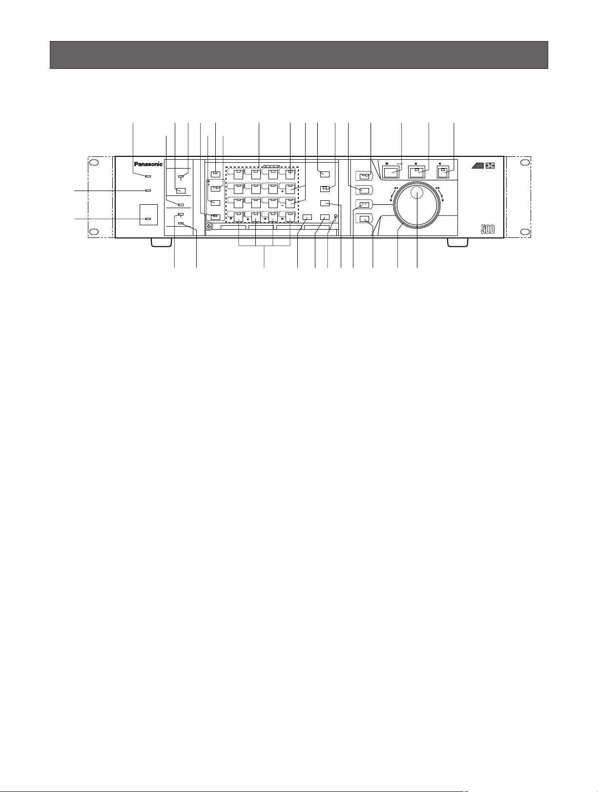
MAJOR OPERATING CONTROLS AND THEIR FUNCTIONS
■ Front View
REMOTE
TIMER
OPERATE
FULL
HDD
SEQUENCE
SET
LOCK
ALARM
ALARM
RESET
ALARM
SUSPEND
MULTISCREEN
SELECT
SETUP
/ESC
GROUP
SELECT
SPOT
MULTISCREEN
DAYLIGHT SAVINGS
EL-ZOOM
COPY
REC PREVIEW
INDEX
STOP BPLAY/ PAUSE REC
FWDREV
ALARM SEARCH
DISPLAY
REC STOP
1 2 3 4
13 14 15 16
9 10 11 12
5 6 7 8
Digital Disk
Recorder
WJ-HD
FS
16
q
w
e t y u !0 !1
rio
!3
!4 !5 !6 !7 !8 !9 @0
!2
@1@3@4@5@6 @2@7@8@9#0#1
B
q Operate Indicator (OPERATE)
Is on when the power of the WJ-HD500B Digital Disk
Recorder is turned on.
w Timer Indicator (TIMER)
Lights to indicate when the TIMER is set to INT (internal
timer) in the setup menu.
e Remote Indicator (REMOTE)
Lights to indicate when the Disk Recorder is controlled
by an outboard device via the Serial or 10/100BASE-T
port on the rear of the Disk Recorder.
r Alarm Suspend Indicator (ALARM SUSPEND)
Lights to indicate that the alarm suspension mode is
selected.
t Alarm Reset Button (ALARM RESET)
This button cancels an activated alarm.
Pressing this button will reset the alarm and return the
system to the condition before the alarm function was
activated.
y Alarm Indicator (ALARM)
This indicator blinks to indicate that an alarm condition
exists.
It changes to a steady light when the alarm is reset
automatically.
To turn the indicator off, press the ALARM RESET button.
u Sequence Button (SEQUENCE)
Runs the assigned sequence on the selected monitor
screen for the specified duration.
During the sequence, pressing this button will pause
the sequence that is being run on the monitor screen.
The LED indicates the status as follows.
On: Sequence is being run.
Blinking: Sequence is in pause mode.
i Multiscreen Selection Button
(MULTISCREEN SELECT)
Selects the multiscreen pattern to be displayed on the
Multiscreen Monitor that is connected to the MULTI
SCREEN OUT on the rear of the Recorder.
Pressing this button will toggle the display on the monitor screen as shown below.
4 → 7 → 9 → 10 → 13 → 16 → 4 screen segments
o Monitor Selection Button (SPOT/MULTISCREEN)
Selects to control the display on the screen for either
the Spot or Multiscreen Monitor.
Pressing this button will toggle the indicator in the button on and off to indicate the selected monitor as shown
below.
On: Indicates the Spot monitor is selected.
Off: Indicates the Multiscreen monitor is selected.
!0 Lock Button (LOCK)
Toggles to enable or disable the button lock function on
both front panels of the Disk Recorder and Remote
Controller.
The LED indicates the status as shown below.
On: The button lock is enabled.
Off: The button lock is disabled.
While On, the button lock will be released only if the
preset password is entered in the password inquiry window.
Page 7

7
!1 Numeric Buttons (1 - 16)
These buttons are used for numeric input into the system such as the video selection, password, etc.
The indicator in the button lights up to indicate as
shown below.
Green: The input is displayed on the monitor.
Yellow: The input is displayed on the monitor and
recorded on the Hard Disk.
Orange: The input is recorded on the Hard Disk (no
display).
!2 Set Button (SET)
During the setup, this button is used to display a submenu in the setup menu if the item has its own setting
menu.
!3 Increment/Decrement Button (+, -)
These buttons are used to zoom in and out the zoomed
image presently displayed on the Multiscreen Monitor.
During the setup, these buttons are used to select the
item parameter in the setup menu.
!4 Recording Stop Button (REC STOP)
Pressing this button will stop the recording.
!5 Recording Preview Button (REC PREVIEW)
Use this button to display the playback image with the
live images on the Multiscreen Monitor.
The LED indicates the status as shown below.
On: The selected playback image is displayed
Blinking: Prompts you to select the numeric button for
displaying the playback image.
!6 Index Button (INDEX)
Displays the all record list (list and thumbnail) or alarm
and emergency list depending on the status of the
ALARM SEARCH button.
!7 Group Selection Button (GROUP SELECT)
Selects the camera group from among group 1, 2, 3
and 4.
The LED will light while any of the groups is selected.
!8 Stop Button (STOP)
Pressing this button will stop the playback.
!9 Playback/Pause Button (PLAY/PAUSE)
Pressing this button will start the playback.
During playback, pressing this button will pause the
playback.
The indicator in the button lights to indicate as shown
below.
On: Indicates that the playback mode is selected.
Blinking: Indicates that the pause mode is selected.
@0 Record Button (REC)
Pressing this button will start the recording manually
when the Timer parameter is set to OFF in the setup
menu.
The indicator in the button lights up to indicate that the
recording mode is selected.
@1 JogDial
Rotate in paused playback to move forward or backward to the next recorded image.
It is also used to select the recording number when the
recorded list is displayed on the monitor.
@2 Shuttle Ring
Rotate in playback or paused playback to search the
recorded images forward or backward at variable
speed.
@3 Display Button (DISPLAY)
Pressing this button will display the recording list with
the search editing area to find the record to be played
back.
@4 Alarm Search Button (ALARM SEARCH)
Selects either the list of alarm (REC+ALM) and emergency recordings or all recordings to be displayed on
the Multiscreen Monitor.
The LED indicates the status of selection as shown
below.
On: Search records for alarm (REC+ALM) and emer-
gency recordings.
Off: Search records for all recordings.
@5 Electronic Zoom Button (EL-ZOOM)
This button is used to zoom an image presently displayed in a single spot on the Multiscreen Monitor.
@6 Daylight Savings Button (DAYLIGHT SAVINGS)
The DAYLIGHT SAVINGS button is recessed inside the
front panel opening. Pressing this button will shift the
internal clock to the summer time or vice versa.
@7 Copy Button (COPY)
Copies the selected images on to the DVD-RAM disk
when the system is equipped the DVD Extension Unit.
@8 Setup/Escape Button (SETUP/ESC)
This button is used in the Disk Recorder’s Setup operation. Pressing this button for two seconds or more will
open the Disk Recorder’s Setup menu on the screen of
the Multiscreen Monitor. During the setup, press this
button to return to the previous setup menu.
Page 8
8
Designation
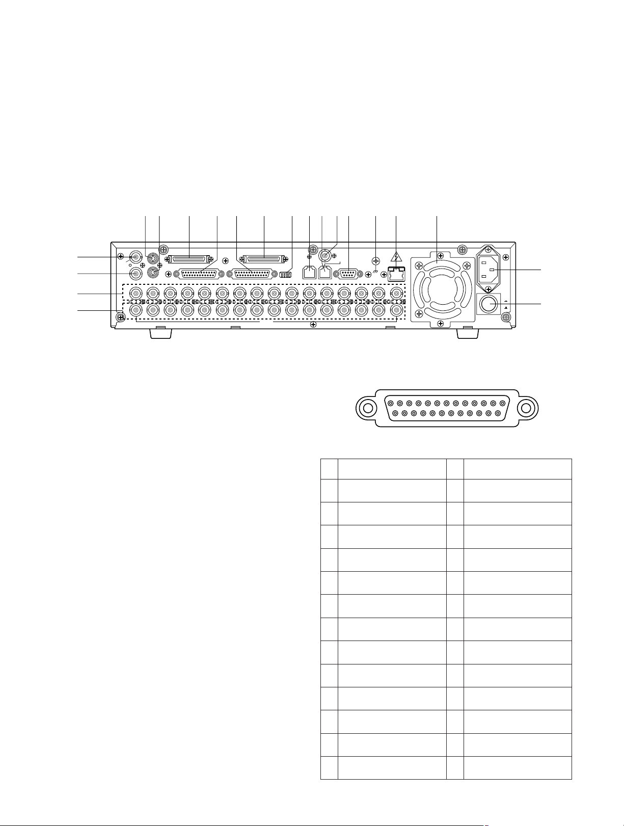
■ Rear View
16161515141413131212111110109988776655443 2231
1
SIGNAL GND
10/100
BASE-T
SPOT
OUT
IN EXT STORAGE COPY
CONTROL ALARM
VIDEO
MODE
DATA
REMOTE(WV-CU50)
GEN-LOCK OUT
SERIAL
POWER
ON
AC
IN
OFF
IN
OUT
OUT
MULTI SCREEN OUT
AUDIO
$1
^0
$2
%9
$3 $4 $5 $6 $7 $8 $9 %0 %1 %2%3 %4 %5 %6
%7
%8
$1 Multiscreen Output Connector (MULTISCREEN OUT)
The video output signal for the Multiscreen Monitor is
provided via this connector.
It can be displayed as the video input in a multiscreen
mode (4, 7, 9, 10, 13,16 screen segments).
It also displays the Recorder’s playback images.
Pressing the SETUP/ESC button for two seconds or
more will automatically select the Multiscreen Monitor
and display the Disk Recorder’s Setup menu.
$22 Spot Output Connector (SPOT OUT)
The video output signal for the Spot Monitor is provided
via this connector.
Displaying the Disk Recorder’s playback is disabled.
$3 Audio Input Connector (AUDIO IN)
For audio input from an external device, if applicable.
$4 Audio Output Connector (AUDIO OUT)
For audio output to an external device, if applicable.
$5 Extension Storage Port (EXT STORAGE)
For connecting the optional Extension Unit.
$6 Control Port (CONTROL)
The port has the functions listed below. Make connections to these pins as needed for operating your system.
Pin
No.
1
2
3
4
5
6
7
8
9
10
11
12
13
Group Recording Output
Manual Recording Output
Emergency Recording
Output
Sequence Timing Output
DVD Remain Space
Output
HDD Remain Space
Output
Thermal Error Input
(Extension 1)
Thermal Error Input
(Extension 2)
Thermal Error Input
(Extension 3)
Thermal Error Input
(Extension 4)
Thermal Error Input
(Extension 5)
Thermal Error Input
(Extension 6)
Thermal Error Input (DVD
Unit)
Pin
No.
14
15
16
17
18
19
20
21
22
23
24
25
Designation
Disk Recorder Error
Output
Ground
Ground
Power Failure Detect Input
Power Failure Proceeding
Output
Power Failure Process
Completion Output
Ground
Emergency Recording
Input
Time Adjustment Output
Daylight Savings Select
Time Adjustment Input
Ground
CONTROL
1
13
14
25
@9 Direction Buttons (CDA B)
These buttons are used to select an area for a zoomed
image displayed on the Multiscreen Monitor.
During the setup, these buttons are used to move the
cursor position in the setup menu of the Disk Recorder.
C: Downward
D: Upward
A: Left
B: Right
#0 Full Indicator (FULL)
Lights to indicate when the available recording space
of the Disk Recorder (HDD) is running low.
#1 Hard Disk Drive Indicator (HDD)
Lights to indicate when the Hard Disk is activated.
The pin assignment of the port is shown below.
Page 9

9
$7 Alarm Port (ALARM)
This port accepts the alarm input from the associated
alarm sensors through either Normally Open or
Normally Closed contacts.
The pin assignment of the port is shown below.
$8 Copy Port (COPY)
For connecting the optional DVD Extension Unit.
$9 Mode Selector (MODE)
Selects data termination for PS
•
Data system expansion.
%0 Data Port (DATA)
Exchanges control data with the external device with
PS
•
Data (Panasonic Security Data) mode.
%1 Remote Port [REMOTE (WV-CU50)]
This port is provided for controlling the Disk Recorder
with the optional WV-CU50 Remote Controller.
To connect to the controller, use a 6-conductor modular
cable supplied as an accessory with the controller.
%2 Gen-lock Output Connector (GEN-LOCK OUT)
This connector is used to connect an external system
for synchronization.
To record images at maximum recording rate, for example 60 fps, connect this output to the cameras to synchronize the system.
%3 Serial Port (SERIAL)
For connecting a Personal Computer.
%4 Signal Ground Terminal (SIGNAL GND)
%5 10/100BASE-T Port (Optional)
An optional Network Board can be installed in the Disk
Recorder.
This port is used to exchange control data with Ethernet
via an Ethernet Hub.
%6 Cooling Fan
Prevents the temperature of the Recorder from rising.
Do not block the ventilation opening on the cover.
%7 AC Inlet Socket (AC IN)
Plug the power cord (supplied as a standard accessory) into this socket and connect it to an AC outlet.
%8 Power Switch (POWER ON/OFF)
This switch turns the power of the Disk Recorder on and
off.
%9 Video Output Connectors (VIDEO OUT 1 - 16)
The video signal connected to the Video Input
Connector (VIDEO IN) is looped through these connectors with an automatic 75 Ω termination.
^0 Video Input Connectors (VIDEO IN 1 - 16)
These connectors accept either a color or B/W composite video signal from the camera.
Pin
No.
Designation
1
2
3
4
5
6
7
8
9
10
11
12
13
Alarm Input 1
Alarm Input 2
Alarm Input 3
Alarm Input 4
Sequence Timing Input
Alarm Reset Output
Ground
Alarm Recover Input
Alarm Output
Alarm Input 10
Alarm Input 11
Alarm Input 12
Alarm Input 13
Pin
No.
14
15
16
17
18
19
20
21
22
23
24
25
Designation
Ground
Alarm Input 5
Alarm Input 6
Alarm Input 7
Alarm Input 8
Alarm Input 9
Ground
+5 V Output (0.2 A)
Recording Timer Select
Input
Alarm Input 14
Alarm Input 15
Alarm Input 16
13
25
ALARM
1
14
Page 10
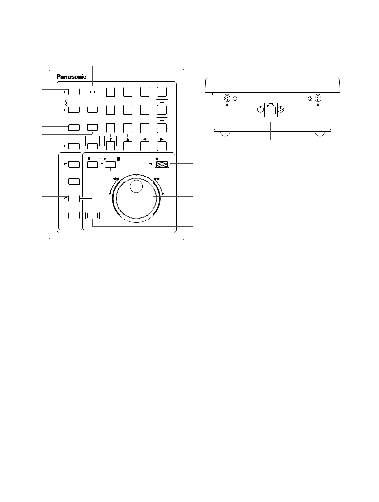
10
■ WV-CU50 Remote Controller
&1 Lock Button (LOCK)
Toggles to enable or disable the button lock function on
both front panels of the Disk Recorder and Remote
Controller.
The LED indicates the status as shown below.
On: The button lock is enabled.
Off: The button lock is disabled.
While On, the button lock will be released only if the
preset password is entered in the password inquiry window.
&2 Monitor Selection Button
(SPOT/MULTISCREEN)
Selects either the Spot or Multiscreen Monitor for which
you wish to control the display on the screen.
The LED indicates the status as shown below.
On: The Spot Monitor is selected.
Off: The Multiscreen Monitor is selected.
&3 Multiscreen Selection Button
(MULTISCREEN SELECT)
Selects the multiscreen pattern to be displayed on the
Multiscreen Monitor.
Pressing this button will change the screen pattern as
follows.
4 → 7 → 9 → 10 → 13 → 16 → 4 screen segments
&4 Recording Preview Button (REC PREVIEW)
Use this button to display the playback image with the
live images on the Multiscreen Monitor.
The LED indicates the status as shown below.
On: The selected playback image is displayed
Blinking: Prompts you to select the numeric button for
displaying the playback image.
&5 Sequence Button (SEQUENCE)
Runs the assigned sequence on the selected monitor
screen for the specified duration.
During the sequence, pressing this button will pause
the sequence that is being run on the monitor screen.
The LED indicates the status as shown below.
On: Sequence is being run.
Blinking: Sequence is in pause mode.
REMOTE
16151413
121110
9
5678
4321
PAUSE
Remote Controller
WV-CU50
FWDREV
LINK
SET
RECPLAY/STOP
STOP
REC
DISPLAY
ALARM
SEARCH
INDEX
GROUP
EL-ZOOMSEQUENCE
PREVIEW
REC
MULTISCREEN
SELECT
SPOT
MULTISCREEN
COPY
LOCK
SELECT
ALARM
RESET
*1
&1
&2
&3
&4
&5
&6
(2
&8
&7
&9
*0
*2 *3
*6
*5
*4
*7
*8
*9
(0
(1
(3
Page 11

11
&6 Electronic Zoom Button (EL-ZOOM)
Use this button to enter or exit the electronic zoom
mode.
In the EL-ZOOM mode an image presently displayed in
single spot can be enlarged and compressed on the
Multiscreen Monitor.
&7 Group Selection Button (GROUP SELECT)
Selects the camera group from among group 1, 2, 3
and 4.
The LED will light while any of the groups is selected.
&8 Index Button (INDEX)
Displays the all record list (list and thumbnail) or alarm
and emergency list depending on the status of the
ALARM SEARCH button.
&9 Alarm Search Button (ALARM SEARCH)
Selects either the list of alarm and emergency recordings or all recordings to be displayed on the
Multiscreen Monitor.
The LED indicates the status of selection as shown
below.
On: Search records for alarm and emergency record-
ings.
Off: Search records for all recordings.
Pressing this button in combination with the STOP button will reset the activated alarm.
*0 Display Button (DISPLAY)
Toggles the all title displays on the Multiscreen Monitor
on and off, such as camera and group titles, operating
status and so forth.
Pressing this button will also display the record list with
the search editing area to find the record to be played
back.
*1 Link Indicator (LINK)
Is lit while the connection is established with the WJHD500B Disk Recorder.
*2 Copy Button (COPY)
Copies the selected images on to the DVD-RAM disk
when the system is equipped the DVD Extension Unit.
*3 Numeric Buttons (1 - 16)
Use these buttons to select the desired camera number
while recording and playing back.
Entering the preset password with these buttons will
release the button lock function.
*4 Set Button (SET)
Use this button to select multiple records in the list for
coping to the DVD-RAM disk.
*5 Increment/Decrement Button (+, -)
Use these buttons to zoom in and out an image while
the zoom mode is selected.
*6 Direction Buttons (CDAB)
Use these buttons to select the desired area to be
zoomed on the Multiscreen Monitor.
C: Downward
D: Upward
A: Left
B: Right
*7 Stop Button (STOP)
Stops playback.
*8 Record Button (RECORD)
Starts recording manually if applicable. The LED turns
on to indicate that the recording mode is selected.
*9 Playback/Pause Button (PLAY/PAUSE)
Pressing this button will start playback.
During playback, pressing this button will pause the
playback.
The LED indicates the status as shown below.
On: Playback mode
Blinking: Pause mode
(0 JogDial
Rotate in the pause mode to advance forward or
reverse to the next recorded image.
Rotating the dial also selects the record number when
the recorded list is displayed on the monitor.
(1 Shuttle Ring
Rotate in the playback or the pause mode to search forward or reverse the recorded images at variable speed.
(2 Recording Stop Button (REC STOP)
Pressing this button will stop the recording.
(3 Remote Port (REMOTE)
Connect with the supplied modular cable to the WJHD500B Disk Recorder.
Page 12
12
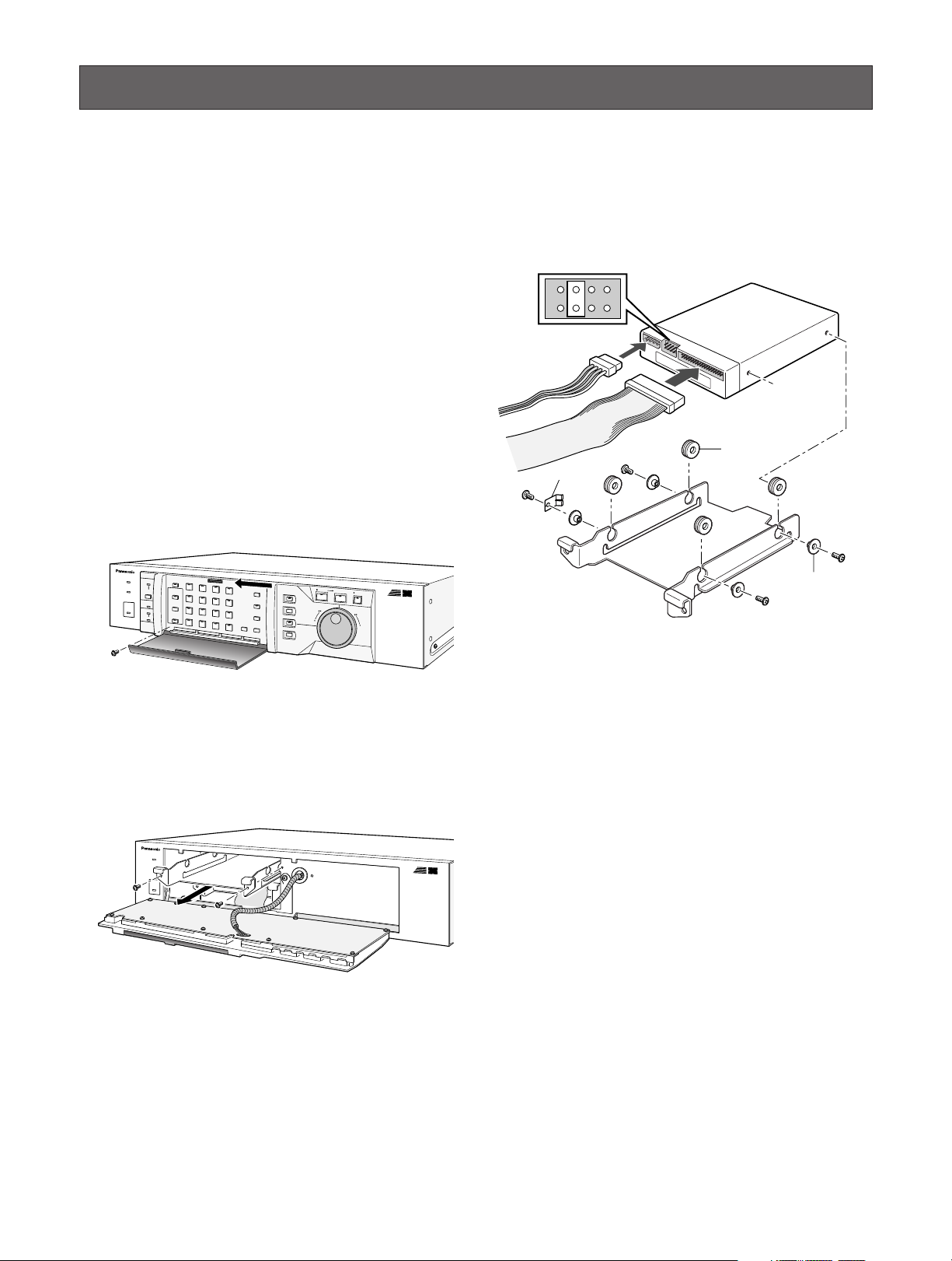
4. Insert the absorbers on to the chassis as shown in the
figure.
5. Place the hard disk on the chassis, then fix it with the
four screws and sleeves with the earth lug as shown in
the figure.
6. Set the unit address with the jumper connector on the
hard disk drive, as shown in the figure, for example.
7. Install the hard disk with the chassis into the Disk
Recorder by sliding it from the front.
8. Plug in the power cable and interface flat cable prepared in the power inlet and interface connector of the
hard disk as shown in the figure.
9. After installing the hard disk, secure the tray chassis
and control panel by tightening the screws.
INSTALLATION
The installations described below should be made by
qualified service personnel or system installers.
■ Installing the Optional Hard Disk
At the time of shipment from the factory, the WJ-HD500B
Disk Recorder is equipped with one hard disk drive; an
optional drive can be installed to increase the hard disk
storage capacity.
To install the optional hard disk, follow the procedures
below.
1. Unplug the power cord from the WJ-HD500B Disk
Recorder, or disconnect the plug from the AC outlet.
2. Remove one screw on the control panel shown in the
figure, then remove the panel by sliding it to the left and
turned over.
3. Remove two screws on the tray chassis in the figure,
then slide out the chassis from the Disk Recorder.
FS
16
absorber
earth lug
sleeve
FS
16
Page 13
14
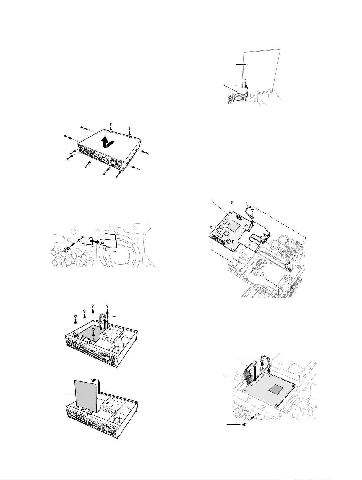
■ Installing the Optional Network Board
The Network Board WJ-HDB502 is installed exclusively in
the WJ-HD500B Disk Recorder.
1. Unplug the power cord from the WJ-HD500B Digital
Disk Recorder, or disconnect the plug from the AC outlet.
2. Remove the top cover of the Disk Recorder by removing the 11 screws, as shown in the figure.
3. Remove the small plate covering the 10/100BASE-T
port hole on the rear of the Disk Recorder by removing
the screw shown in the figure.
4. Remove the 6 screws on the board, as shown below,
disconnect the CN403, then turn over the Main Board
with the front side up.
5. Connect one end of the supplied flat cable to the
brown-colored receptacle on the main board, as shown
in the figure.
6. Place the main board and CN403 as before, and
secure them by tightening the reinstalled screws.
7. Remove a screw on the bracket as shown in the figure,
and then fix a supplied grounding wire by tightening the
removed screw.
8. Place the Network Board on the brackets, as shown in
the figure, then secure it with the grounding wire by
tightening the 4 supplied screws.
9. Fix the 10/100BASE-T port to the rear panel with the
screw removed in step 3.
10. Connect the supplied DC power cable and the other
end of the flat cable to the board, as shown in the figure.
11. After installing the board, secure the top cover by tightening the screws.
Disk Recorder
WJ-HD500B
10/100BASE-T
Main Board
Flat Cable
(Supplied)
Network Board
Grounding Wire
CN403
Main Board
Rear Panel
DC Power Cable
(Supplied)
Flat Cable
(Supplied)
10/100BASE-T
Tighten
Page 14
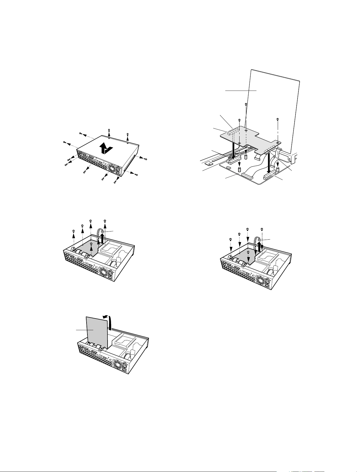
13
5. Place the Motion Detector Board on the Analog Board,
as shown below, and plug in the boards.
6. Fix both boards with the 3 supplied screws, as shown
below.
7. After installing the board, connect CN403 and the main
board, then secure them by tightening the screws
shown below.
■ Installing the Optional Motion
Detector Board
The Motion Detector Board WJ-HDB501 is installed exclusively in the WJ-HD500B Disk Recorder.
1. Unplug the power cord from the WJ-HD500B Digital
Disk Recorder, or disconnect the plug from the AC outlet.
2. Remove the top cover of the Disk Recorder by removing the 11 screws, as shown below.
3. Remove the 6 screws on the board, as shown below,
and disconnect the CN403.
4. Turn over the Main Board with the front side up.
Disk Recorder
WJ-HD500B
Main Board
Motion Detector
Board
CN601
CN501
CN101
Analog Board
CN502
CN403
Main Board
CN403
Page 15
15
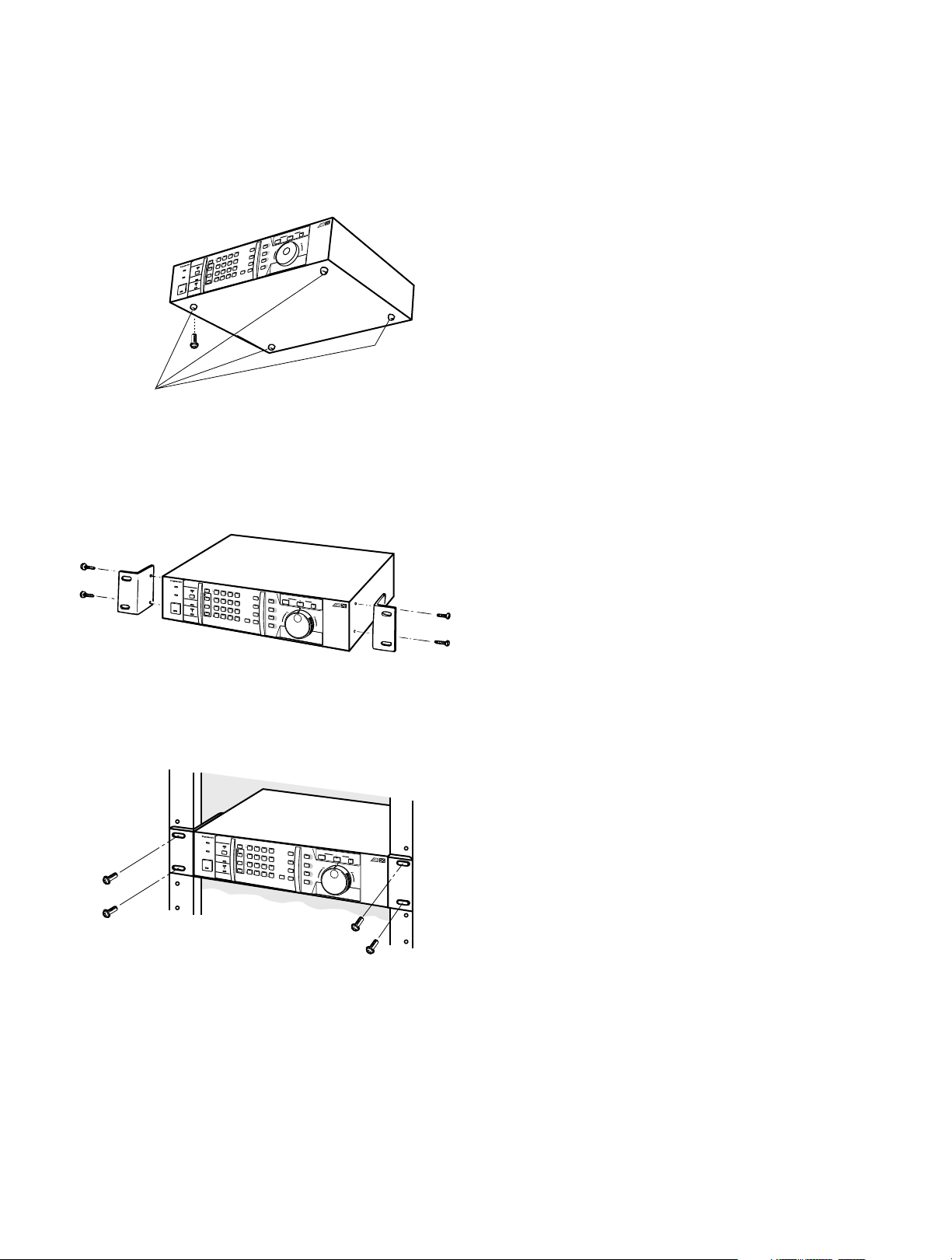
■ Mounting into the Rack
The Disk Recorder can be mounted into the rack as
described below.
1. Remove the four rubber feet by removing the four
screws from the bottom of the Disk Recorder.
2. Place the rack mounting brackets on both sides of the
Disk Recorder and tighten with the four supplied
screws (M4 X10).
3. Install the Disk Recorder with the rack mounting brackets in the rack, securing it with four screws (not included).
Cautions:
• The cooling fan inside the Disk Recorder is subject to
wear and needs to be replaced periodically.
• Do not block the ventilation opening or slots in the
cover to prevent the appliance from overheating.
Always keep the temperature in the rack below 45°C
(113°F).
• If the rack is subject to vibration, secure the rear of the
appliance to the rack by using additional mounting
brackets (procured locally).
Digital Disk
R
e
c
o
r
d
e
r
WJ-HD
500
B
•
•
•
F
S
1616
Remove 4 rubber feet
500
500
16
•
F
S
16
•
•
D
ig
ita
l D
is
k
R
e
c
o
rd
e
r
W
J
-
H
D
500
B
•
F
S
16
•
•
D
ig
ita
l D
is
k
Recorder
W
J
-H
D
5
0
0
B
Page 16
16
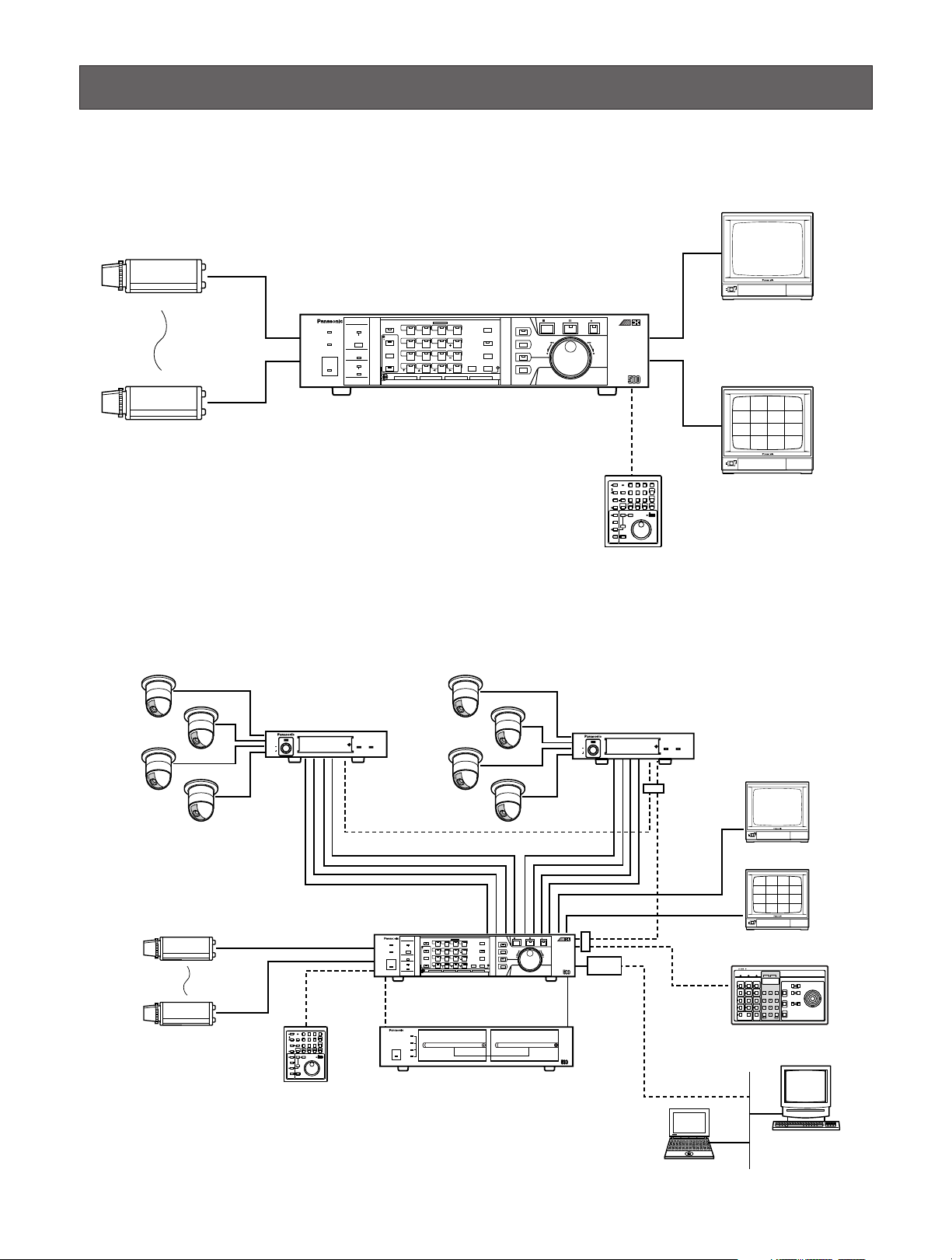
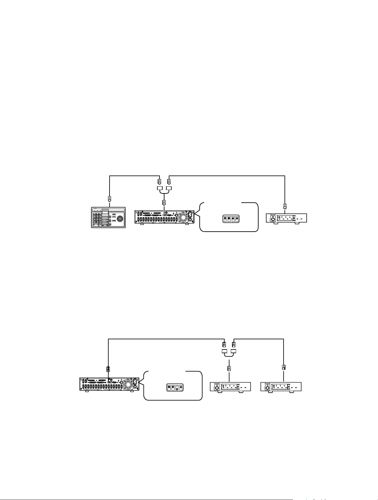
CONNECTIONS
Shown below are examples of system connections.
<Basic System>
ON
OFF
POWER
ON
OFF
POWER
REMOTO
TIMER
OPERATE
FULL
HDD
SEQUENCE
SET
LOCK
ALARM
ALARM
RESET
ALARM
SUSPEND
MULTISCREEN
SELECT
SET UP
/ESC
GROUP
SELECT
SPOT
MULTISCREEN
DAYLIGHT SAVINGS
EL-ZOOM
COPY
REC PREVIEW
INDEX
STOP PLAY/ PAUSE REC
FWDREV
ALARM SEARCH
DISPLAY
REC STOP
1 2 3 4
13 14 15 16
9 10 11 12
5 6 7 8
Digital Disk
Recorder
WJ-HD B
FS
1616
Spot Monitor
Multiscreen Monitor
Digital Disk Recorder WJ-HD500B
Remote Controller
WV-CU50
16 Cameras
ON
OFF
POWER
REMOTO
TIMER
OPERATE
FULL
HDD
SEQUENCE
SET
LOCK
ALARM
ALARM
RESET
ALARM
SUSPEND
MULTISCREEN
SELECT
SET UP
/ESC
GROUP
SELECT
SPOT
MULTISCREEN
DAYLIGHT SAVINGS
EL-ZOOM
COPY
REC PREVIEW
INDEX
STOP PLAY/ PAUSE REC
FWDREV
ALARM SEARCH
DISPLAY
REC STOP
1 2 3 4
13 14 15 16
9 10 11 12
5 6 7 8
Digital Disk
Recorder
WJ-HD
FS
1616
ON
OFF
POWER
Spot Monitor
Multiscreen Monitor
Digital Disk Recorder WJ-HD500B
Extension Unit WJ-HDE500B
(with optional HDs)
Remote Controller
WV-CU50
8 Camreras
HDD 1
HDD 2
HDD 3
HDD 4
Extension Unit WJ-HDE
OPERATE
System Controller
POWER
ON
OFF
ALARM
Data Multiplex Unit WJ-MP204
ALARM
SUSPEND
POWER
ON
OFF
ALARM
Data Multiplex Unit WJ-MP204
ALARM
SUSPEND
System Controller
LAN
Ethernet
(100 BASE-T Cable)
WJ-HDB502
PS-Data
Link
WJ-MP204WJ-MP204
B
B
<System Expansion>
Page 17
17
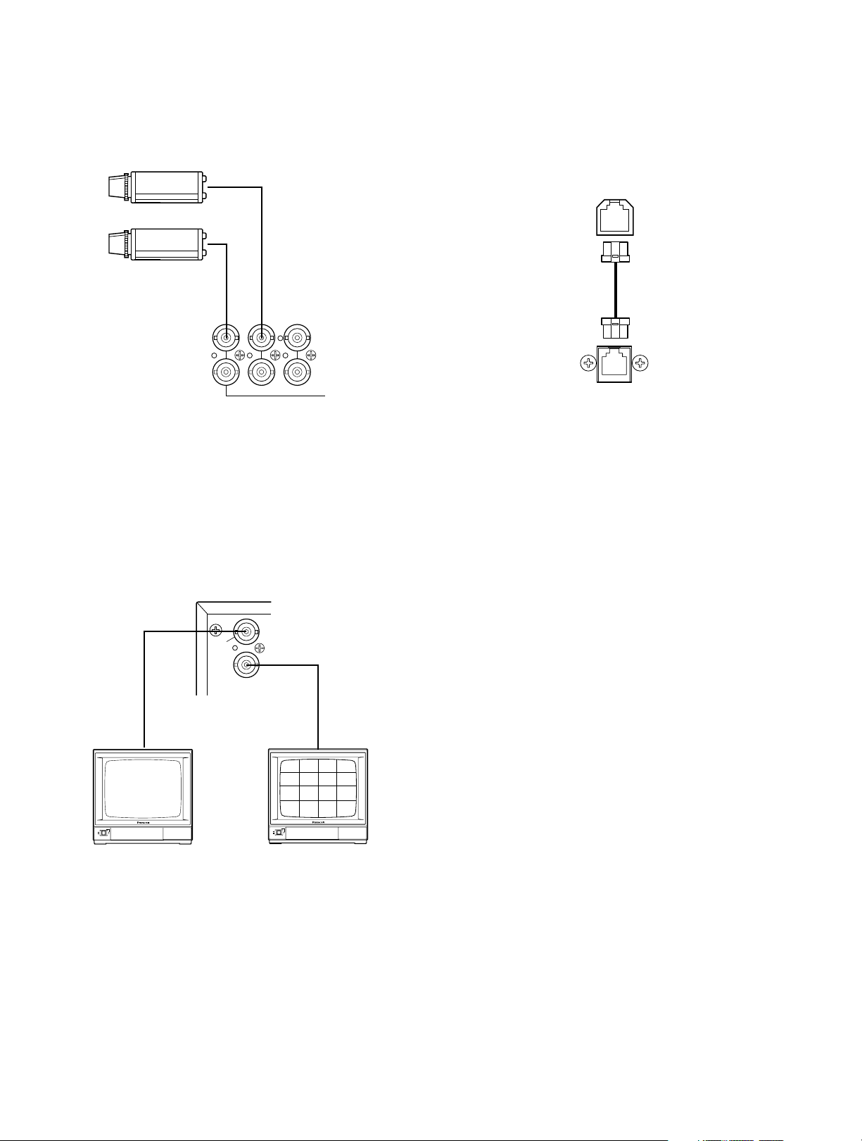
■ Connection with the Remote
Controller
Connect the Remote Controller to the REMOTE port on the
rear of the Disk Recorder with the supplied modular cable.
■ Connection with the Camera Sites
Connect cameras (or camera site equipment) to the VIDEO
IN connectors (1 to 16) on the rear of the Disk Recorder
with the coaxial cable.
■ Connection with the Monitors
Connect the monitors to the SPOT OUT connector and
MULTISCREEN OUT connector on the rear of the Disk
Recorder with the coaxial cable.
1616151514
IN
OUT
14
REMOTE
(WV-CU50)
Remote Controller
WV-CU50
Disk Recorder
WJ-HD500B
SPOT
OUT
OUT
MULUTI SCREEN
POWER
ON
OFF
Spot Monitor
POWER
ON
OFF
Multiscreen Monitor
Page 18
18
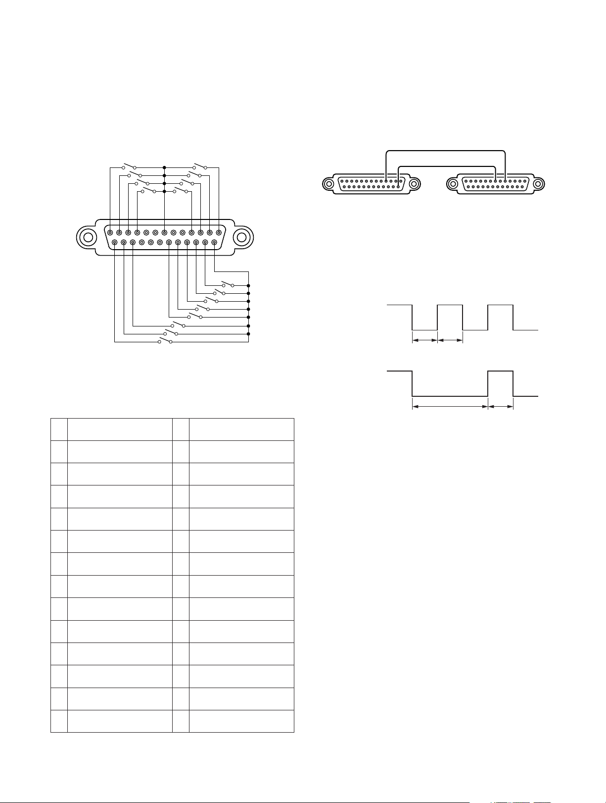
■ Alarm Port Connection
The ALARM port can be used for connecting the alarm sensor and alarm control switches. It is also used to synchronize the sequence as shown below.
• Connect the sensor switches to the ALARM port on the
rear of the Disk Recorder, as shown in the example
below.
Designation
Pin
No.
1
2
3
4
5
6
7
8
9
10
11
12
13
Alarm Input 1
Alarm Input 2
Alarm Input 3
Alarm Input 4
Sequence Timing Input
Alarm Reset Output
Ground
Alarm Recover Input
Alarm Output
Alarm Input 10
Alarm Input 11
Alarm Input 12
Alarm Input 13
Pin
No.
14
15
16
17
18
19
20
21
22
23
24
25
Designation
Ground
Alarm Input 5
Alarm Input 6
Alarm Input 7
Alarm Input 8
Alarm Input 9
Ground
+5 V Output (0.2 A)
Recording Timer Select
Input
Alarm Input 14
Alarm Input 15
Alarm Input 16
• The sequence timing can be assigned to one of the
recorders when the multiple Disk Recorders are
equipped in the system.
Connect the CONTROL port and ALARM port as shown
below.
Refer to the SEQ TIMING in the SEQUENCE SETUP
menu for further setting.
If the sequence timing is controlled from the outboard
device, the input signal is required as shown in the figure. For example, the WJ-HD500B output is also in the
figure.
Sequence Timing Output
Sequence Timing Input
13
25
ALARM
1
14
Ground
4
15
CONTROL
WJ-HD500B (1st)
Ground
5
7
ALARM
WJ-HD500B (2nd)
input
100 ms 100 ms
WJ-HD500B
output
500 ms 100 ms
Page 19
19
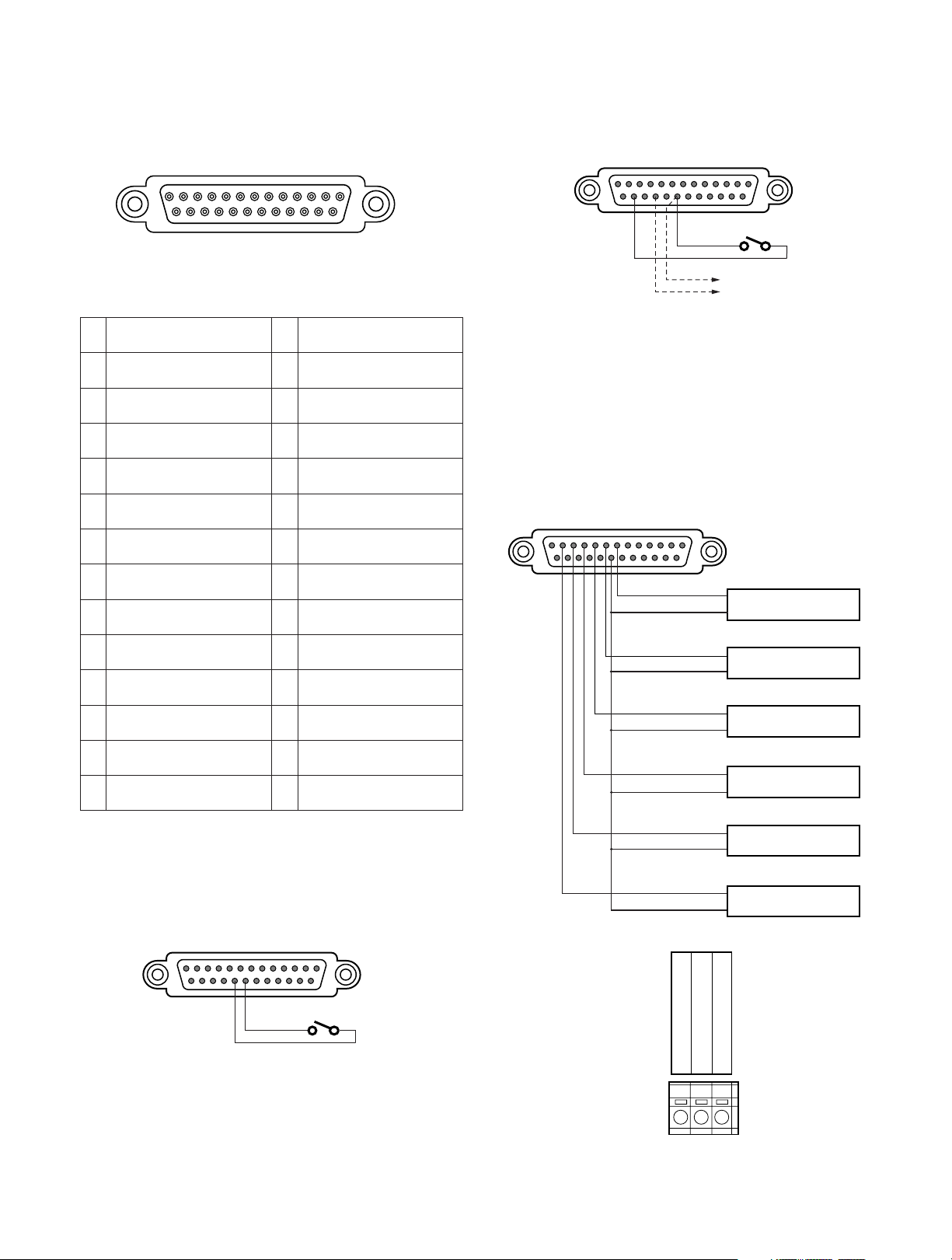
• Time adjustment can be enabled connecting with the
external device as shown below.
• The Extension Units are installed in the system for
extending its disk capacity.
Connect each thermal error output from the Extension
Units with the CONTROL Port on the rear of the WJHD500B Disk Recorder as shown below.
The WJ-HD500B will display the warning for thermal
error on the monitor.
■ Control Port Connection
The CONTROL port can be used for controlling the system
with the outboard device as shown below.
• Emergency Recording can be enabled receiving the
input from the connected external device.
Designation
Pin
No.
1
2
3
4
5
6
7
8
9
10
11
12
13
Group Recording Output
Manual Recording Output
Emergency Recording
Output
Sequence Timing Output
DVD Remain Space
Output
HDD Remain Space
Output
Thermal Error Input
(Extension 1)
Thermal Error Input
(Extension 2)
Thermal Error Input
(Extension 3)
Thermal Error Input
(Extension 4)
Thermal Error Input
(Extension 5)
Thermal Error Input
(Extension 6)
Thermal Error Input (DVD
Unit)
Pin
No.
14
15
16
17
18
19
20
21
22
23
24
25
Designation
Disk Recorder Error
Output
Ground
Ground
Power Failure Detect Input
Power Failure Proceeding
Output
Power Failure Process
Completion Output
Ground
Emergency Recording
Input
Time Adjustment Output
Daylight Savings Select
Time Adjustment Input
Ground
13
1
WJ-HD500B
CONTROL Port
13
1
25
CONTROL
14
WJ-HD500B
CONTROL Port
13
1
25
24
20
14
Time Adjustment Output
WJ-HD500B
CONTROL Port
13
25
789101112
20
1
14
Extension Unit #1
Thermal Error Out
G
Extension Unit #2
Thermal Error Out
G
Extension Unit #3
Thermal Error Out
G
Extension Unit #4
Thermal Error Out
G
Extension Unit #5
Thermal Error Out
G
Extension Unit #6
Thermal Error Out
G
25
21
20
14
Terminal board on
the Extension Unit
G
THERMAL ERROR OUT
NC
Page 20
20
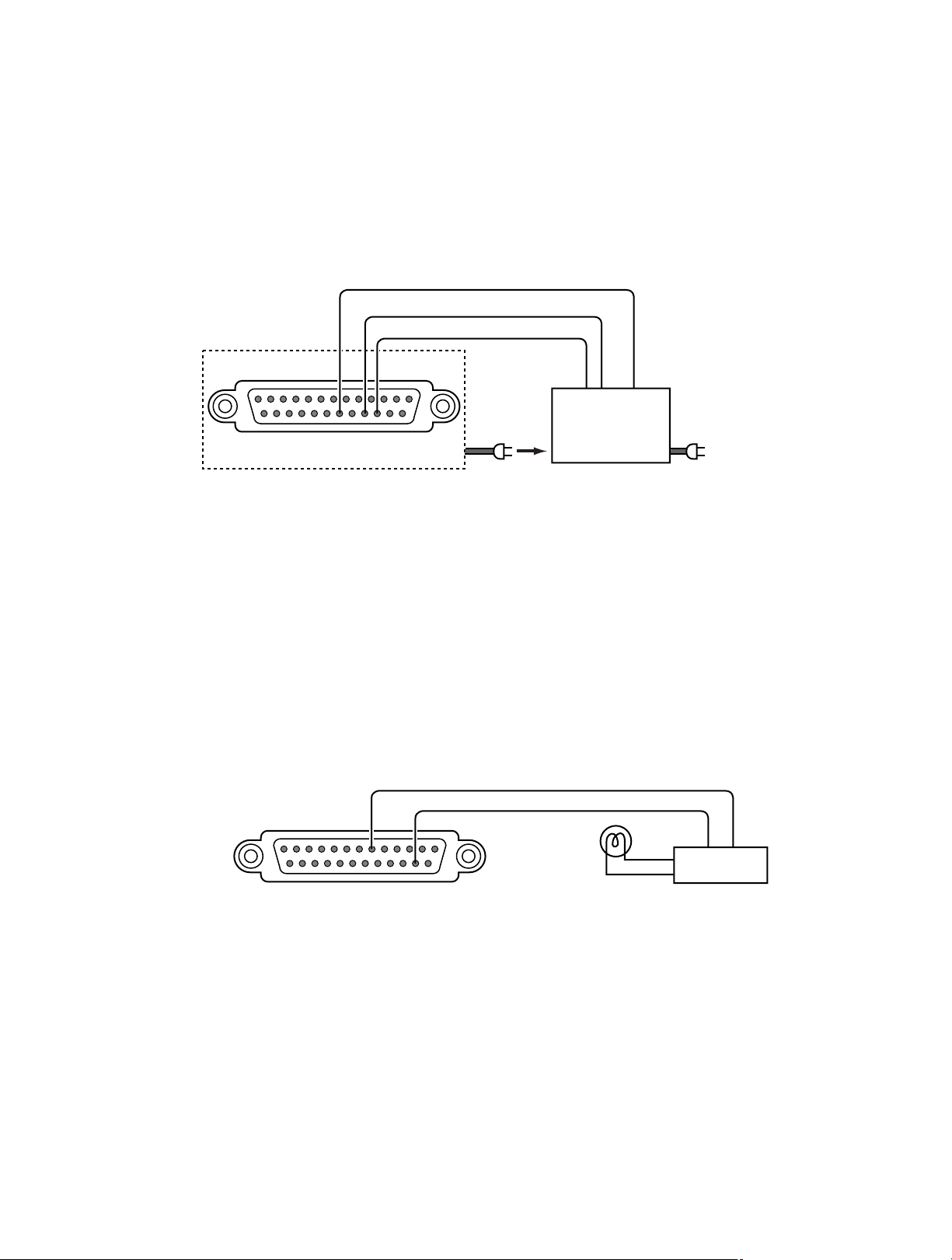
■ Connection with the Uninterrupted Power Supply (UPS)
• The figure shows an example of how to connect a UPS as protection against power failures.
• When a power failure detect input is received from the UPS, the disk recorder's power failure process starts to process this
signal to turn off its power supply.
• When the power failure process is completed, the disk recorder outputs a signal to the UPS.
• When the UPS receives the completion signal from the disk recorder, the disk recorder's power is turned off
■ Connection with CONTROL output
• Signal outputs (Pins #1-6, 18) can be used to connect alarm devices such as a buzzer or lamp to inform you of the operation status by sounding a buzzer or lighting a lamp when a signal is output.
• The figure below shows an example of how to connect an alarm output (Pin #6) to warn of low remaining HDD capacity.
Disk Recorder
WJ-HD500B
Power Failure Process
Completion Output
Power Failure Detect Input
Ground Common
(19) (17) (16)
CONTROL
Power Cable
UPS Shut Down
Line Fail signal
(Normally Open)
Uninterrupted
Power Supply
C
Before connecting the UPS,
refer to the manual of
your UPS.
to AC outlet
(Remaining HDD Capacity Alarm Output)
(6)
CONTROL Input/Output
(15)
Ground
Alarm Device
Relay, etc.
Page 21
21
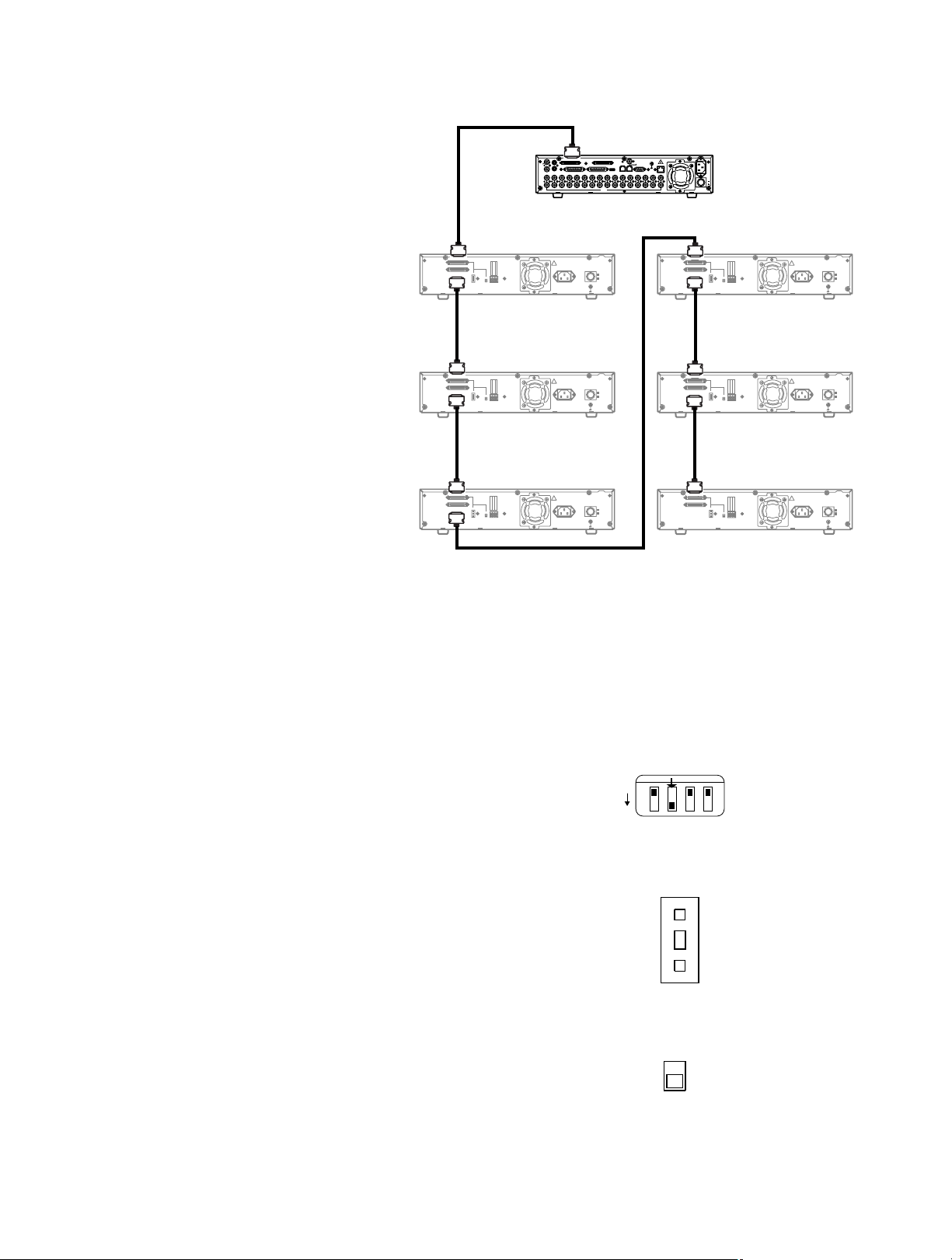
■ Connection with the Extension Units
● SCSI Connection
The Digital Disk Recorder WJ-HD500B controls
the extension units through the SCSI chain.
1. Connect the supplied SCSI cable between
the EXT STORAGE port on the WJ-HD500B
and the EXT IN port on the 1st extension
unit.
2. Connect the supplied SCSI cable between
the EXT OUT port on the 1st extension unit
and the EXT IN port on the 2nd extension
unit.
Repeat connections in the same manner for
all additional extension units.
3. The 3rd extension unit must be a WJ-
HDE505B if a further extension unit is connected. Use WJ-HDE500B if the 3rd unit is
located at the end of the SCSI chain.
Up to 6 extension units can be added.
● Switch Setting
Data termination and SCSI number settings are required, as
shown below.
1. Set the MODE switch #2 on the rear of the WJ-HD500B
to ON when connecting with an extension unit.
2. Set the SCSI ID number for each unit by pressing the
[–] or [+] button on the rear of the Extension Unit.
0 to 5 are applicable to the extension units.
Note: SCSI ID 6 and 7 are reserved for WJ-HD500B
Disk Recorder.
3. Set the termination switches on the rear of the Extension
Units to ON or OFF.
ON: Is applied to the extension unit located at the end
of the SCSI chain.
OFF: Is used for units other than the end unit.
SIGNAL GND
WER
C IN
SCSI ID
EXT OUT
EXT IN
TERMINA
OR
GND
THERMAL ERR
OR OUT
NC
OFF
ON
ON
OFF
SIGNAL GND
WER
C IN
SCSI ID
EXT OUT
EXT IN
TERMINA
OR
GND
THERMAL ERR
OR OUT
NC
OFF
ON
ON
OFF
SIGNAL GND
WER
C IN
SCSI ID
EXT OUT
EXT IN
TERMINA
OR
GND
THERMAL ERR
OR OUT
NC
OFF
ON
ON
OFF
SIGNAL GND
WER
C IN
SCSI ID
EXT OUT
EXT IN
TERMINA
OR
GND
THERMAL ERR
OR OUT
NC
OFF
ON
ON
OFF
SIGNAL GND
WER
C IN
SCSI ID
EXT OUT
EXT IN
TERMINA
OR
GND
THERMAL ERR
OR OUT
NC
OFF
ON
ON
OFF
SIGNAL GND
WER
C IN
SCSI ID
EXT OUT
EXT IN
TERMINA
OR
GND
THERMAL ERR
OR OUT
NC
OFF
ON
ON
OFF
Digital Disk Recorder
WJ-HD500B
SCSI ID = 6 and 7
IN EXT STORAGE COPY
EXT STORAGE
SPOT
OUT
OUT
CONTROL ALARM
MULTI SCREEN OUT
AUDIO
16161515141413131212111110109988776655443 2231
IN
OUT
Extesion Unit #1
WJ-HDE500B
SCSI ID = 5
EXT IN
OR OUT
EXT OUT
SCSI ID
GND
THERMAL ERR
NC
–
TERMINA
TOR
+
ON
OFF
AC IN
SIGNAL GND
Extesion Unit #2
WJ-HDE500B
GND
OR OUT
THERMAL ERR
NC
SCSI ID = 4
AC IN
SIGNAL GND
SCSI CableSCSI Cable SCSI Cable
EXT IN
EXT OUT
SCSI ID
–
TERMINA
TOR
+
ON
OFF
GEN-LOCK OUT
SIGNAL GND
REMOTE(WV-CU50)
DATA
BASE-T
10/100
SERIAL
MODE
VIDEO
AC
IN
ON
OFF
1
POWER
Extesion Unit #4
WJ-HDE500B
SCSI ID = 2
EXT IN
OR OUT
POPOWER
ON
OFF
EXT OUT
SCSI ID
GND
THERMAL ERR
NC
–
TERMINA
TOR
+
ON
OFF
AC IN
POPOWER
ON
OFF
SIGNAL GND
Extesion Unit #5
WJ-HDE500B
OR OUT
GND
THERMAL ERR
TOR
ON
OFF
NC
SCSI ID = 1
AC IN
SIGNAL GND
POPOWER
ON
OFF
SCSI Cable
POPOWER
ON
OFF
SCSI CableSCSI Cable
EXT IN
EXT OUT
SCSI ID
–
TERMINA
+
Extesion Unit #3
WJ-HDE500B or
WJ-HDE505B*
NC
SCSI ID = 3
AC IN
POPOWER
SIGNAL GND
EXT IN
EXT OUT
ON
OFF
SCSI ID
–
+
EXT IN
OR OUT
EXT OUT
SCSI ID
GND
THERMAL ERR
–
TERMINA
TOR
+
ON
OFF
Extesion Unit #6
OR OUT
GND
THERMAL ERR
NC
TERMINA
TOR
ON
OFF
WJ-HDE500B
SCSI ID = 0
AC IN
POPOWER
ON
OFF
SIGNAL GND
* Use a WJ-HDE505B for the 3rd unit position if additional units are installed.
Use a WJ-HDE500B if the 3rd position is the end of the SCSI chain.
1 2 3 4
ON
MODE
SCSI ID
–
1
+
TERMINATOR
ON
OFF
Page 22
22
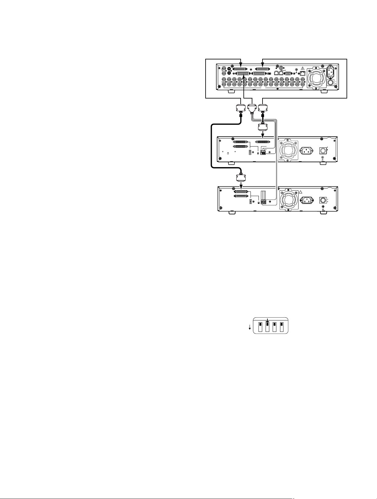
●
Switch Settings
1. Set MODE switch #2 on the rear of the WJ-HD500B to
OFF when connecting a DVD Extension Unit without an
optional HDD.
Set the MODE switch to ON if other Extension Units are
installed in the system.
2. Set the SCSI ID and TERMINATION of the Extension
Units as required.
■ Connection with the DVD Extension Unit
The WJ-HD500B Digital Disk Recorder controls the WJHDE510B DVD Extension Unit through the SCSI chain.
<Connection with the DVD Extension Unit
without HDD>
The figure shows a WJ-HDE510B without an HDD.
The DVD-RAM is used for backup of the data recorded
on the WJ-HD500B Digital Disk Recorder.
1. Connect between the COPY port on the WJ-HD500B
and the COPY IN port on the 1st DVD Extension Unit
with the supplied (WJ-HDE510B) SCSI cable.
Plug the cable end with magnetic core into the COPY
port, and the other ends into the COPY IN port.
2. Connect between the EXT STORAGE port on the WJHD500B and the EXT IN port on the 2nd Extension
Unit with the supplied (WJ-HDE510B) SCSI cable.
Plug the cable end with magnetic core into the EXT
STORAGE port, and the other ends into the EXT IN
port.
The system can be expanded by up to 6 Extension
Units.
To connect the other Extension Units, refer to the
operating instructions of each unit for further information.
EXT
STORAGE
Digital Disk Recorder
WJ-HD500B
SCSI ID=6 and 7
IN EXT STORAGE COPY
SPOT
OUT
OUT
MULTI SCREEN OUT
IN
OUT
CONTROL ALARM
AUDIO
16161515141413131212111110109988776655443 2231
SCSI cable
(supplied with
Extension Unit)
COPY IN
EXT IN
EXT OUT
HDD
INSTALLED
NOT INSTALLED
EXT IN
EXT IN
EXT OUT
Extension Unit #2
WJ-HDE500B/HDE505B
SCSI ID=0 to 5
COPY port
MODE
VIDEO
CONTROL port
SCSI cable (supplied)
COPY IN
G
THERMAL ERROR OUT
SCSI ID
NC
-
TERMINATOR
1
+
ON
OFF
SCSI ID
GND
THERMAL ERROR OUT
NC
–
TERMINATOR
+
ON
OFF
GEN-LOCK OUT
SIGNAL GND
REMOTE(WV-CU50)
DATA
BASE-T
10/100
SERIAL
1
DVD Extension Unit #1
WJ-HDE510B
SCSI ID= not set
AC IN
Terminal board
AC IN
POWER
SIGNAL
POWER
SIGNAL GND
AC
IN
ON
OFF
POWER
ON
OFF
GND
ON
OFF
1 2 3 4
ON
MODE
Page 23
23
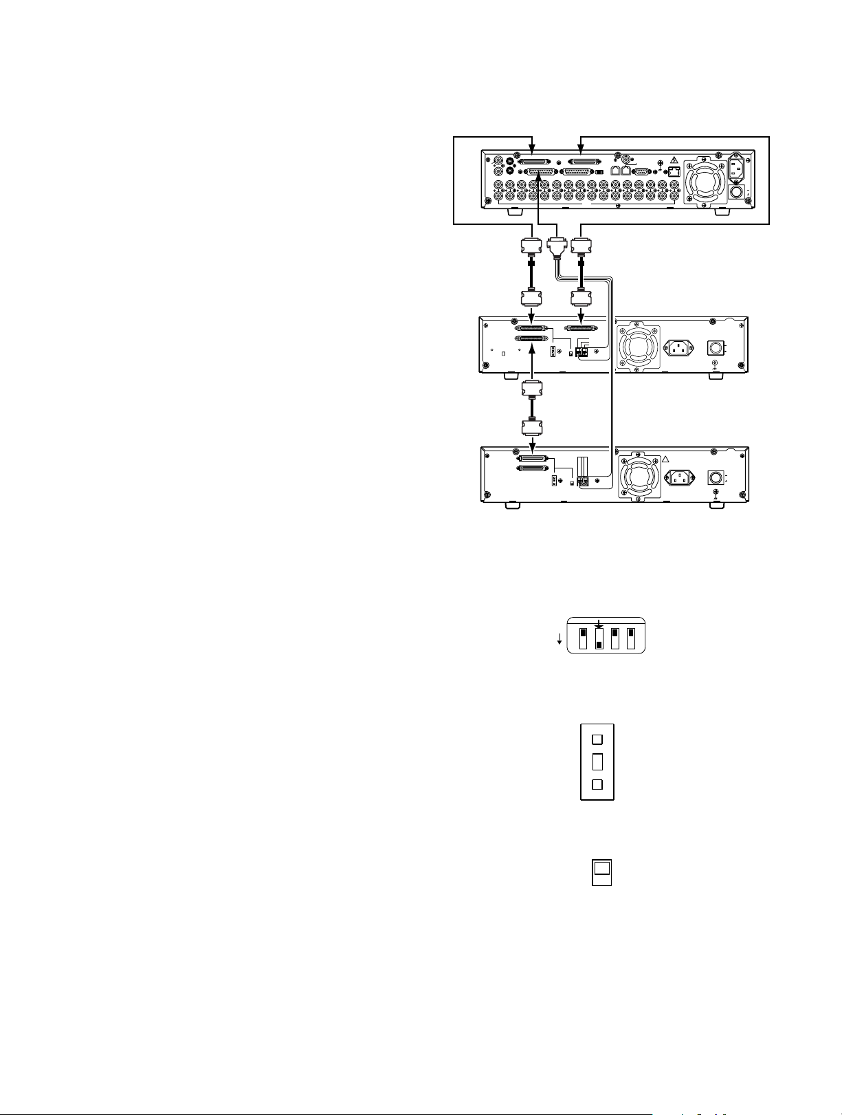
<Connection with the DVD Extension Unit
with HDD>
The figure shows the WJ-HDE510B with an HDD.
The DVD-RAM is used for backup of the data recorded
on the WJ-HD500B Digital Disk Recorder as well as for
storing the data of the extension hard disk drive units in
the system.
1. Connect between the COPY port on the WJ-HD500B
and the COPY IN port on the 1st DVD Extension Unit
with the supplied (WJ-HDE510) SCSI cable.
Plug the cable end with magnetic core into the
COPY port, and the other ends into the COPY IN
port.
2. Connect between the EXT STORAGE port on the
WJ-HD500B and the EXT IN port on the 1st DVD
Extension Unit with the supplied (WJ-HDE510B)
SCSI cable.
Plug the cable end with magnetic core into the EXT
STORAGE port, and the other ends into the EXT IN
port.
Repeat the connection steps for any subsequent
extension units.
The system can be expanded by up to 6 Extension
Units. To connect the other Extension Units, refer to
the operating instructions of each unit for further
information.
●
Switch Settings
1. Set MODE switch #2 on the rear of the WJ-HD500B to
ON when connecting a DVD Extension Unit with an
optional HDD.
2. Set the SCSI ID for the DVD Extension Unit and each
subsequent Extension Unit with the – or + selector on
the rear of each Unit.
0 to 5: IDs for Extension Units.
Note: SCSI ID 6 and 7 are reserved for the WJ-HD500B
Digital Disk Recorder.
3. Set the termination switches on the rear of the Extension
Units to ON or OFF.
ON: Is applied to the extension unit located at the end
of the SCSI chain.
OFF: Is used for units other than the end unit.
EXT
STORAGE
Digital Disk Recorder
WJ-HD500B
SCSI ID=6 and 7
IN EXT STORAGE COPY
SPOT
OUT
OUT
MULTI SCREEN OUT
AUDIO
16161515141413131212111110109988776655443 2231
IN
OUT
SCSI cable
(supplied)
EXT IN
EXT IN
EXT OUT
HDD
INSTALLED
NOT INSTALLED
EXT OUT
EXT IN
EXT IN
EXT OUT
COPY port
GEN-LOCK OUT
REMOTE(WV-CU50)
DATA
CONTROL ALARM
VIDEO
SERIAL
MODE
CONTROL port
SCSI cable (supplied)
DVD Extension Unit #1
G
THERMAL ERROROUT
NC
WJ-HDE510B
SCSI ID=0 to 5
COPY
IN
SCSI ID
-
TERMINATOR
1
+
COPY IN
ON
OFF
SCSI cable
(supplied with
Extension Unit)
Terminal board
SCSI ID
GND
THERMAL ERROR OUT
NC
–
TERMINATOR
+
ON
OFF
Extension Unit #2
WJ-HDE500B/HDE505B
SCSI ID=0 to 5
SIGNAL GND
POWER
SIGNAL
POWER
SIGNAL GND
AC
IN
ON
OFF
POWER
ON
OFF
GND
ON
OFF
BASE-T
10/100
1
AC IN
AC IN
1 2 3 4
ON
MODE
SCSI ID
–
1
+
ON
OFF
Page 24
24
■ Connection to PS•Data Compatible Equipment
Note the following when connecting the Disk Recorder to equipment with PS•Data capability.
q Connect the controller and PS
•
Data equipment at the ends of the PS•Data line.
w Set the termination to ON for the units at both ends of the PS
•
Data line.
Use the MODE selector on the rear of the WJ-HD500B Disk Recorder to set the termination.
e Use the optional RS-485 cable for connection.
Note: To be able to use PS
•
Data mode, the communication functions need to be set up in the PS•Data SETUP menu.
● MODE Selector Setting
• Set DIP switch 4 of the MODE selector as follows for data termination.
ON: If the disk recorder is connected at the end of the PS
•
Data line.
OFF: If the Disk Recorder is not connected at the end of the PS
•
Data line.
Example:
• If the optional WJ-HDB502 Network Board is installed as a controller in the Disk Recorder, the system can be controlled
from a PC through the Disk Recorder.
Set DIP switch 3 of the MODE selector as follows for data termination.
ON: If the Network Board is connected at the end of the PS
•
Data line.
OFF: If the Network Board is not connected at the end of the PS
•
Data line.
For a system that has no system controller and is controlled through the Disk Recorder, for example, set DIP switch 3 of the
MODE selector to ON position.
Note: If the system has a system controller, set DIP switch 3 to OFF position.
SERIAL
SIGNAL GND
BASE-T
10/100
1
AC
IN
ON
OFF
POWER
RS-485 Cable
MODE Selector
(3 : OFF, 4 : OFF)
↑
ON
1234
UNIT
ALARM
0
1
9
POWER
2
8
3
7
4
6
5
ON
1234
OFF
RESET
SUSPEND SET UP
ESCSET
Data Multiplex Unit WJ-MP204
ALARM
SUSPEND
ALARM
Data Multiplex Unit
Termination : ON
RS-485 Cable
System Controller
System Controller
IN EXT STORAGE COPY
SPOT
OUT
OUT
CONTROL ALARM
MULTI SCREEN OUT
AUDIO
16161515141413131212111110109988776655443 2231
IN
OUT
GEN-LOCK OUT
REMOTE(WV-CU50)
DATA
MODE
VIDEO
Disk Recorder
Termination : ON
RS-485 Cable
MODE Selector
IN EXT STORAGE COPY
SPOT
OUT
OUT
CONTROL ALARM
MULTI SCREEN OUT
AUDIO
16161515141413131212111110109988776655443 2231
IN
OUT
GEN-LOCK OUT
SIGNAL GND
REMOTE(WV-CU50)
DATA
BASE-T
10/100
SERIAL
MODE
1
VIDEO
POWER
Disk Recorder Data Multiplex Unit
AC
IN
ON
OFF
(3 : ON, 4 : OFF)
↑
ON
1234
POWER
ON
OFF
Termination : OFF
UNIT
ALARM
0
1
9
2
8
3
7
RESET
4
6
5
1234
SUSPEND SET UP
ESCSET
Data Multiplex Unit WJ-MP204
ALARM
RS-485 Cable
POWER
ALARM
SUSPEND
ON
OFF
Data Multiplex Unit
Termination : ON
UNIT
ALARM
0
1
9
2
8
3
7
SUSPEND SET UP
RESET
4
6
5
ESCSET
1234
ALARM
Data Multiplex Unit WJ-MP204
ALARM
SUSPEND
Page 25
25
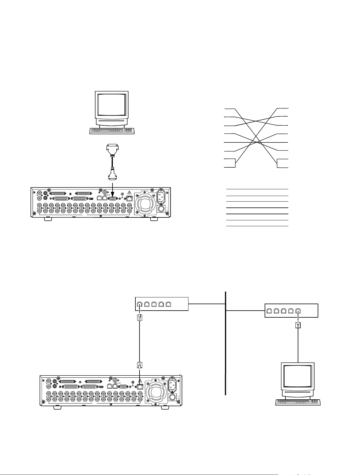
■ Connection with the PC
There are two options to communicate with the PC, the first is using Serial Port and the second is via Ethernet, when the specified Network Board is installed in the Disk Recorder.
● Serial Port Connection
The SERIAL Port on the rear of the Disk Recorder conforms to RS-232C, and it can communicate with the PC by connecting as
shown in the figure.
● 10/100BASE-T Port Connection
If the optional Network Board is installed in the WJ-HD500B Disk Recorder, it is enabled control from the PC via Ethernet.
Shown in the figure is an example for connection.
Personal Computer
D-sub9
or
D-sub25
D-sub9
IN EXT STORAGE COPY
SPOT
OUT
OUT
AUDIO
CONTROL ALARM
VIDEO
MULTI SCREEN OUT
16161515141413131212111110109988776655443 2231
IN
OUT
GEN-LOCK OUT
REMOTE(WV-CU50)
DATA
MODE
SERIAL
Digital Disk Recorder
SIGNAL GND
WJ-HD500B
DB9
1
2
3
4
5
6
7
8
WJ-HD500B
DB9
BASE-T
10/100
1
AC
IN
ON
OFF
POWER
2 (RXD)
3 (TXD)
4 (ER)
5 (GND)
6 (DR)
7 (RTS)
8 (CTS)
PC
DB9
1
2
3
4
5
6
7
8
PC
DB25
2 (TXD)
3 (RXD)
6 (DR)
7 (GND)
20 (ER)
5 (CTS)
4 (RTS)
10/100BASE-T Cable
(Locally Procured)
IN EXT STORAGE COPY
SPOT
OUT
OUT
MULTI SCREEN OUT
16161515141413131212111110109988776655443 2231
IN
OUT
AUDIO
CONTROL ALARM
MODE
VIDEO
GEN-LOCK OUT
REMOTE(WV-CU50)
DATA
SERIAL
Digital Disk Recorder
SIGNAL GND
LAN
Hub
Hub
10/100
BASE-T
1
AC
IN
ON
OFF
POWER
Personal Computer
Page 26

26
Page 27

27
PREPARATIONS
Page 28

28
POWER UP PROCEDURE
Before operating the Disk Recorder, confirm that the cameras and peripherals are connected correctly and securely
and all system components are turned on.
1. Turn on the Disk recorder by pressing the POWER
switch located on the rear of the Disk Recorder. Make
sure that the OPERATE indicator on the front panel is
illuminated.
2. After you completed the start, the Disk Recorder will run
through a series of instructions for the system on the
Multiscreen Monitor.
3. If the Disk Recorder is powered up successfully, the
display as shown below appears, then the camera
images appear on the monitor screen.
Note:
If during a system check the display shown below
appears on the monitor screen, it will be followed by
the DISK MENU after five seconds.
The DISK MENU-Display indicates the status of the
hard disks, and shows the causes why this menu
was called up.
• Optional Extension Unit is installed [ADD]
Requires disk formatting in the Extension Unit.
• Replaced Hard Disk []]
Requires disk formatting for a replaced Hard
Disk.
• Detached Hard Disk [LOST]
Requires disk relocation in the system.
• Hard Disk malfunctions []]
Refer servicing to qualified service personnel.
• Hard Disk access error [ERR]
¢¢GB indicates the hard disk capacity.
Note:
If the Disk Recorder is left in this state for about five
minutes, it will automatically restart by reconfiguring the
system (disk remove).
Normal camera images will appear on the monitor
screen.
[ SYSTEM CHECK ]
PLEASE WAIT
[ SYSTEM CHECK ]
YOU HAVE TO CONFIGURE DISKS
PLEASE WAIT
DISK MENU
MAIN 1:¢¢GB 2:¢¢GB
EXT5 1:¢¢GB 2:¢¢GB 3:¢¢GB 4:¢¢GB
EXT4 1:* 2:* 3:ADD 4:ADD
EXT3 1:LOST 2:LOST 3:LOST 4:LOST
EXT2 1:LOST 2:LOST 3:LOST 4:LOST
EXT1 1:- 2:- 3:- 4:EXT0 1:- 2:- 3:- 4:EXT DVD:-
REMOVE FORMAT
RESTART
SELECT ITEM AND PRESS [SET] KEY
[ SYSTEM CHECK ]
SYSTEM CHECK DONE!
PLEASE WAIT
DISK MENU: [SETUP] KEY
Page 29

29
FORMATTING THE HARD DISK
The Hard Disk requires formatting before it can be used for
storing images, as shown below.
• When the Hard Disk in the Disk Recorder is replaced.
(Disk formatting is required for the replaced Hard Disk.)
• When the optional extension units are operated for the
first time after installation.
(Disk formatting is required for the Hard Disk in the
Extension Unit.)
Notes:
• Remember that by formatting the hard disk all previ-
ously recorded data on the disk will be erased.
• If the Disk Recorder is set up with the mirroring
function, the replaced Hard Disk is automatically
copying the data from the other disk of the pair after
the disk was formatted.
Copying data will take about two hours for a disk
with a capacity of 30 GB.
Follow the procedures described below to format the Hard
Disk in the unit.
1. Power up the Disk Recorder by pressing the POWER
switch.
2. The Disk Recorder will run through a series of instructions for the system on the Multiscreen Monitor.
The display as shown below appears on the monitor,
then the DISK MENU shown below will be displayed
after five seconds.
3. Move the cursor to FORMAT in the menu by pressing
the A or B button, then press the SET button.
The FORMAT MENU shown below appears on the monitor screen.
4. Select the ALL password (5-digit) by pressing the
Numeric buttons (1 - 10).
Refer to the password setup in the SYSTEM SETUP
menu for further details.
The factory default setting is 12345.
• To select "0" for numeric input, press the numeric 10
button.
• Entering an input will automatically check the password.
If the password is not correct, "PASSWORD
ERROR!" is displayed on the monitor screen and
the display returns to step 2.
To enter the password again, repeat procedures 3
and 4.
• To quit entering the password, press the SETUP/
ESC button.
5. If the password is correct, the instructions shown below
appear in the lower-left corner of the menu.
FORMAT MENU
MAIN 1:¢¢GB 2:¢¢GB
EXT5 1:¢¢GB 2:¢¢GB 3:¢¢GB 4:¢¢GB
EXT4 1:ADD 2:ADD 3:ADD 4:ADD
EXT3 1:- 2:- 3:- 4:EXT2 1:- 2:- 3:- 4:EXT1 1:- 2:- 3:- 4:EXT0 1:- 2:- 3:- 4:EXT DVD:-
PASSWORDB-----
[ SYSTEM CHECK ]
YOU HAVE TO CONFIGURE DISKS
PLEASE WAIT
DISK MENU
MAIN 1:¢¢GB 2:¢¢GB
EXT5 1:
EXT4 1:ADD 2:ADD 3:ADD 4:ADD
EXT3 1:- 2:- 3:- 4:EXT2 1:- 2:- 3:- 4:EXT1 1:- 2:- 3:- 4:EXT0 1:- 2:- 3:- 4:EXT DVD:-
REMOVE FORMAT
RESTART
SELECT ITEM AND PRESS [SET] KEY
¢¢GB 2:¢¢GB 3:¢¢GB 4:¢¢GB
FORMAT MENU
MAIN 1:¢¢GB 2:¢¢GB
EXT5 1:¢¢GB 2:¢¢GB 3:¢¢GB 4:¢¢GB
EXT4 1:ADD 2:ADD 3:ADD 4:ADD
EXT3 1:- 2:- 3:- 4:EXT2 1:- 2:- 3:- 4:EXT1 1:- 2:- 3:- 4:EXT0 1:- 2:- 3:- 4:EXT DVD:-
1DISK ALL ALL MIRROR
RESTART
SELECT ITEM AND PRESS [SET] KEY
Page 30

30
6. Select either "1DISK" or "ALL" by pressing the A or B
button, then press the SET button.
1DISK: Enables formatting only a specified Hard Disk.
ALL: Enables formatting all Hard Disks.
If the "1DISK" is selected in the menu, move the cursor
to the Hard Disk number to be formatted by pressing
the A, B, D or C button, then press the SET button.
The instructions appear in the lower-left corner of the
menu, as shown below.
7. Select "YES" in the menu by pressing the A or B but-
ton, then press the SET button to start formatting.
8. When the formatting is completed, "FORMAT DONE!"
appears in the lower center of the menu.
<1DISK Selection>
• Then the menu display will return to step 6 for formatting another Hard Disk.
Repeat the procedure 6 to 8 to format the another
disk.
• To quit formatting, move the cursor to RESTART in
the menu by pressing the A, B, D or C button,
then press the SET button to restart the Disk
Recorder.
Normal camera images will appear on the monitor.
<ALL Selection>
• Normal camera images will appear on the monitor
after five seconds.
1DISK FORMAT
MAIN 1:¢¢GB 2:¢¢GB
EXT5 1:
EXT4 1:ADD 2:ADD 3:ADD 4:ADD
EXT3 1:- 2:- 3:- 4:EXT2 1:- 2:- 3:- 4:EXT1 1:- 2:- 3:- 4:EXT0 1:- 2:- 3:- 4:EXT DVD:-
EXECUTE? YES NO
SELECT YES/NO AND PRESS [SET] KEY
¢¢GB 2:¢¢GB 3:¢¢GB 4:¢¢GB
1DISK FORMAT
MAIN 1:¢¢GB 2:¢¢GB
EXT5 1:¢¢GB 2:¢¢GB 3:¢¢GB 4:¢¢GB
EXT4 1:ADD 2:ADD 3:ADD 4:ADD
EXT3 1:- 2:- 3:- 4:EXT2 1:- 2:- 3:- 4:EXT1 1:- 2:- 3:- 4:EXT0 1:- 2:- 3:- 4:EXT DVD:-
FORMAT DONE!
Page 31

31
4. Select DVD FORMAT in the menu by pressing the D or
C button, then press the SET button.
The DVD FORMAT menu as shown below appears on
the monitor.
5. Select "YES" in the menu by pressing the A or B button, then press the SET button to start formatting.
6. When the formatting is completed, "COMPLETED!"
appears in the center of the menu.
7. To exit from the menu, press and hold the SETUP/ESC
button for two seconds or more.
FORMATTING THE DVD-RAM DISK
The DVD-RAM Disk requires formatting before it can be
used for storing images when the DVD Extension Unit is
installed in the system for backup of the recording data.
Notes:
• Remember that by formatting the DVD-RAM disk all
previously recorded data on the disk will be erased.
• Confirm that the AUTO COPY (EVENT) and AUTO
COPY (EMERGENCY) parameters in the DVD menu
are set to OFF.
Otherwise disk formatting is disabled.
Follow the procedures described below to format the DVDRAM Disk in the unit.
1. Insert the DVD-RAM disk into the DVD Extension Unit.
2. Press and hold the SETUP/ESC button for two seconds
or more to display the WJ-HD500 SETUP menu on the
screen of the Multiscreen Monitor.
3. Select DVD in the menu by pressing the D or C button,
then press the SET button.
The DVD menu as shown below appears on the monitor.
WJ-HD500 SETUP *.**
TIMER OFF
REC SETUP
COMMON SETUP
*MANUAL WITHOUT AUDIO
*TIMER WITHOUT AUDIO
*EMERGENCY WITHOUT AUDIO
MULTIPLEXER SETUP
ALARM SETUP
DISPLAY SETUP
COMMUNICATION SETUP
SYSTEM SETUP
DVD
10-1 DVD FORMAT
EXECUTE? YES NO
10-1 DVD FORMAT
FORMATTING!
DON'T TURN OFF THE POWER
10 DVD
DVD FORMAT
*AUTO COPY(EVENT) OFF
AUTO COPY(EMERGENCY) OFF
DVD DISKEND STOP
DVD FULL 1%
10-1 DVD FORMAT
COMPLETED!
Page 32

32
The mirroring function uses an auxiliary array of inexpensive disks to record the same data on two disks at the same
time.
If an error or malfunction occurs on one of the hard disks,
the other disk still records the data normally. This ensures
reliability of the system, since the data will always be available on one of the disks.
To use this function, the Disk Recorder must be equipped
with an optional internal hard disk. Refer to the installation
for details of installing the disk.
Note: It is recommended to set up this function when
the Disk Recorder is operated for the first time.
Otherwise the previously recorded data will be
erased by activating this function.
The mirroring function can only be set during the power up
procedure, as shown below.
1. Turn on the Disk recorder by pressing the POWER
switch located on the rear of the Disk Recorder. Make
sure that the OPERATE indicator on the front panel is
illuminated.
2. After you completed the start, the Disk Recorder will run
through a series of instructions for the system on the
Multiscreen Monitor.
MIRRORING FUNCTION
3. If the Disk Recorder is powered up successfully, the
displays as shown below will appear.
Press the SETUP/ESC button within five seconds, and
the DISK MENU shown below will appear on the monitor.
4. Move the cursor to “FORMAT” on the table by pressing
the A, B, D or C button, then press the SET button.
The FORMAT MENU will appear on the monitor.
Camera Images
Auxiliary
Recording
Manual Recorder
Group 1
Group 2
Group 3
Group 4
Emergency Recorder
Manual Recorder
Group 1
Group 2
Timer
Recorder
Group 3
Group 4
Emergency Recorder
Recording
Timer
Recorder
WJ-HD500 Disk 1 (Master) WJ-HD500 Disk 2 (Slave)
[ SYSTEM CHECK ]
SYSTEM CHECK DONE!
PLEASE WAIT
DISK MENU: [SETUP] KEY
DISK MENU
MAIN 1:¢¢GB 2:¢¢GB
EXT5 1:
EXT4 1:* 2:* 3:ADD 4:ADD
EXT3 1:LOST 2:LOST 3:LOST 4:LOST
EXT2 1:LOST 2:LOST 3:LOST 4:LOST
EXT1 1:- 2:- 3:- 4:EXT0 1:- 2:- 3:- 4:EXT DVD:-
REMOVE FORMAT
RESTART
SELECT ITEM AND PRESS [SET] KEY
¢¢GB 2:¢¢GB 3:¢¢GB 4:¢¢GB
[ SYSTEM CHECK ]
PLEASE WAIT
FORMAT MENU
MAIN 1:¢¢GB 2:¢¢GB
EXT5 1:
EXT4 1:ADD 2:ADD 3:ADD 4:ADD
EXT3 1:- 2:- 3:- 4:EXT2 1:- 2:- 3:- 4:EXT1 1:- 2:- 3:- 4:EXT0 1:- 2:- 3:- 4:EXT DVD:-
PASSWORDB-----
¢¢GB 2:¢¢GB 3:¢¢GB 4:¢¢GB
Page 33

33
To deactivate the mirror function:
• Select “MIRROR RELEASE” in the menu by pressing
the A, B, D or C button, then press the SET button
during the step 7 procedure.
When the mirror function is activated, the “MIRROR
RELEASE” is displayed in the menu as shown below.
• All procedures are similar to setting the mirror function.
5. Select the ALL password (5-digit) by pressing the
Numeric buttons (1 - 10).
Refer to the password setup in the SYSTEM SETUP
menu for further details.
The factory default setting is 12345.
• To select "0" for numeric input, press the numeric 10
button.
• Entering an input will automatically check the password.
If the password is not correct, "PASSWORD
ERROR!" is displayed on the monitor screen and
the display returns to step 3.
To enter the password again, repeat procedures 4
and 5.
• To quit entering the password, press the SETUP/
ESC button.
6. If the password is correct, the instructions shown below
appear in the lower-left corner of the menu.
7. Move the cursor to “ALL MIRROR” on the table by
pressing the A, B, D or C button, then press the SET
button. The ALL MIRROR FORMAT menu will appear on
the monitor.
8. Select “YES” in the menu by pressing the A or B button, then press the SET button to start formatting.
9. When the formatting is completed, "FORMAT DONE!"
appears in the lower-center of the menu.
Normal camera images will appear on the monitor after
five seconds.
FORMAT MENU
MAIN 1:¢¢GB 2:¢¢GB
EXT5 1:¢¢GB 2:¢¢GB 3:¢¢GB 4:¢¢GB
EXT4 1:ADD 2:ADD 3:ADD 4:ADD
EXT3 1:- 2:- 3:- 4:EXT2 1:- 2:- 3:- 4:EXT1 1:- 2:- 3:- 4:EXT0 1:- 2:- 3:- 4:EXT DVD:-
1DISK ALL ALL MIRROR
RESTART
SELECT ITEM AND PRESS [SET] KEY
FORMAT MENU(MIRRORING)
MAIN 1:
EXT5 1:¢¢GB 2:¢¢GB 3:¢¢GB 4:¢¢GB
EXT4 1:* 2:* 3:ADD 4:ADD
EXT3 1:LOST 2:LOST 3:LOST 4:LOST
EXT2 1:LOST 2:LOST 3:LOST 4:LOST
EXT1 1:- 2:- 3:- 4:EXT0 1:- 2:- 3:- 4:EXT DVD:OK
1DISK ALL ALL MIRROR MIRROR RELEASE
RESTART
SELECT ITEM AND PRESS [SET] KEY
¢¢GB 2:¢¢GB
ALL MIRROR FORMAT
MAIN 1:¢¢GB 2:¢¢GB
EXT5 1:
EXT4 1:* 2:* 3:ADD 4:ADD
EXT3 1:LOST 2:LOST 3:LOST 4:LOST
EXT2 1:LOST 2:LOST 3:LOST 4:LOST
EXT1 1:- 2:- 3:- 4:EXT0 1:- 2:- 3:- 4:EXT DVD:OK
EXECUTE? YES NO
SELECT YES/NO AND PRESS [SET] KEY
¢¢GB 2:¢¢GB 3:¢¢GB 4:¢¢GB
Page 34

34
3. Select “YES” in the menu by pressing the A or B but-
ton, then press the SET button to execute the disk
remove.
4. When the remove is completed, “DONE!” appears in
the lower-left corner of the menu.
The selected disks are displayed with “–” in the menu
Normal camera images will appear on the monitor after
five seconds.
DISK REMOVE
The Disk Recorder will display the DISK MENU on the
Multiscreen Monitor during the power-up procedure, if it
detects that there are changes to the previous system, as
shown below.
• Hard disks were removed from the Disk Recorder or the
extension unit.
• One or more of the hard disks installed in the Disk
Recorder or the extension unit have failed.
The Disk Recorder and Extension Units will operate normally by recomposing the system (disk remove) as shown
below.
1. Turn on the Disk recorder by pressing the POWER
switch located on the rear of the Disk Recorder.
The Disk Recorder will run through a series of instructions for the system on the Multiscreen Monitor, then
display the DISK MENU as shown below on the monitor.
2. Move the cursor to “REMOVE” in the menu by pressing
the A, B, D or C button, then press the SET button.
The DISK REMOVE menu as shown below will appear
on the monitor screen.
The disk remove is applied to hard disks displayed with
“LOST” and “✽” in the menu.
DISK MENU
MAIN 1:¢¢GB 2:¢¢GB
EXT5 1:¢¢GB 2:¢¢GB 3:¢¢GB 4:¢¢GB
EXT4 1:* 2:* 3:ADD 4:ADD
EXT3 1:LOST 2:LOST 3:LOST 4:LOST
EXT2 1:LOST 2:LOST 3:LOST 4:LOST
EXT1 1:- 2:- 3:- 4:EXT0 1:- 2:- 3:- 4:EXT DVD:-
REMOVE FORMAT
RESTART
SELECT ITEM AND PRESS [SET] KEY
DISK REMOVE
MAIN 1:¢¢GB 2:¢¢GB
EXT5 1:
EXT4 1:- 2:- 3:ADD 4:ADD
EXT3 1:- 2:- 3:LOST 4:LOST
EXT2 1:LOST 2:LOST 3:LOST 4:LOST
EXT1 1:- 2:- 3:- 4:EXT0 1:- 2:- 3:- 4:EXT DVD:OK
NOW EXECUTING. PLEASE WAIT
¢¢GB 2:¢¢GB 3:¢¢GB 4:¢¢GB
■
DISK REMOVE
MAIN 1:¢¢GB 2:¢¢GB
EXT5 1:
EXT4 1:- 2:- 3:ADD 4:ADD
EXT3 1:- 2:- 3:- 4:-
EXT2 1:- 2:- 3:- 4:-
EXT1 1:- 2:- 3:- 4:EXT0 1:- 2:- 3:- 4:EXT DVD:OK
DONE!
¢¢GB 2:¢¢GB 3:¢¢GB 4:¢¢GB
DISK REMOVE
MAIN 1:¢¢GB 2:¢¢GB
EXT5 1:
EXT4 1:* 2:* 3:ADD 4:ADD
EXT3 1:LOST 2:LOST 3:LOST 4:LOST
EXT2 1:LOST 2:LOST 3:LOST 4:LOST
EXT1 1:- 2:- 3:- 4:EXT0 1:- 2:- 3:- 4:EXT DVD:OK
EXECUTE? YES NO
(FOR “LOST”,“*” DISK)
¢¢GB 2:¢¢GB 3:¢¢GB 4:¢¢GB
DISK REMOVE
MAIN 1:¢¢GB 2:¢¢GB
EXT5 1:
EXT4 1:- 2:- 3:ADD 4:ADD
EXT3 1:- 2:- 3:- 4:-
EXT2 1:- 2:- 3:- 4:-
EXT1 1:- 2:- 3:- 4:EXT0 1:- 2:- 3:- 4:EXT DVD:OK
FAILED!
¢¢GB 2:¢¢GB 3:¢¢GB 4:¢¢GB
Page 35

35
■ Status Display
The status display shows the system status of the Disk
Recorder.
It is displayed on the screen of the Multiscreen Monitor during recording and playback and contains the following
information.
The status display is only available on the screen of the
Multiscreen Monitor.
Pressing the DISPLAY button toggles all displays on the
monitor on and off.
(The Spot Monitor only displays the Group Title and
Camera Title.)
q Time Display
Displays the hours (24-hour), minutes, and seconds.
“✽” indicates that summer time mode is selected.
w Date Display
e Recording Status and Recording Number Display
Displays the recording status and recording number
currently being played back.
The recording number is automatically assigned when
recording.
REC ✽✽%: Indicates that images are being recorded.
(✽✽ indicates the remaining space of the Hard Disk
when the HDD DISKEND is set to STOP in the setup
menu.)
EMERGENCY: Indicates that an Emergency Recording
is being made.
✽✽✽✽✽✽✽✽✽: Recording Number (during playback)
MONITORS AND DISPLAYS
■ Spot and Multiscreen Monitor
The WJ-HD500B Disk Recorder can be connected to two
Monitors.
The monitor displays the video signal according to the connection made, as shown below.
Spot Monitor: The monitor that is connected to the
SPOT OUT connector on the rear of the Recorder.
It only displays the video input in single spot or single sequence.
Displaying the Disk Recorder’s playback is disabled.
Multiscreen Monitor: The monitor that is connected to
the MULTISCREEN OUT connector on the rear of
the Recorder.
It can display the video input in multiscreen mode
(4, 7, 9, 10, 13,16 screen segments).
It also displays the Recorder’s playback images.
Pressing the SETUP/ESC button for two seconds or
more will automatically select this monitor and display the Disk Recorder’s Setup menu.
Note: When a Disk Recorder equipped with the
optional WJ-HDB502 Network Board is
accessed from a PC via a network, the Multiscreen Monitor screen will turn blue and will not
display live camera images. The monitor
screen will display the message "Controlled
(Network)".
Pressing one of the numeric buttons (1 -
16) will display the selected camera images in a
single spot. This function is not available when
CAMERA GENLOCK ON is selected on the
COMMON SETUP menu.
Disk Recorder
WJ-HD500B
SPOT
OUT
OUT
MULUTI SCREEN
qy
w
e
r
t
u
!0
i
o
POWER
ON
OFF
Spot Monitor
POWER
ON
OFF
Multiscreen Monitor
Page 36

36
r Warning Display
Displays the status in case of Disk Recorder trouble.
THERMAL ✽: Indicates thermal error in the Disk
Recorder or the extension units.
(✽ indicates the extension unit number)
HDD ✽✽%: Is displayed when the remaining space of
the Hard Disk reaches a specified value.
(✽✽ indicates the remaining capacity.)
DISK FULL: Is displayed when the remaining space of
the Hard Disk reaches 0 %.
DVD ✽✽%: Indicates the remaining space of the DVD-
RAM Disk. (✽✽ indicates the remaining capacity.)
ALTERED: Is displayed when the recorded data are
altered.
ERROR ✽-✽: Indicates access error of the Hard Disk.
(✽-✽ indicates the Hard Disk number in the Disk
Information menu)
ERROR: Indicates that the other errors have occurred.
PWR LOSS: Is displayed when the UPS
(Uninterrupted Power Supply) detects a power
failure.
WARNING ✽-✽: Indicates that the hard disk will
become failure soon. Replace ones for system
complement.
PROTECTED: Indicates that the DVD-RAM disk is
not write enabled.
NO DISK: Indicates that the DVD-RAM disk is not
inserted in the DVD Extension Unit.
FORMAT ERROR or
MEDIUM ERROR: Indicates that the DVD-RAM disk
is not identified.
DVD BUSY: Indicates that the DVD Extension Unit
is not ready or is being accessed.
REMOVED HD: Indicates that the HDD has been
removed due to access errors. Identify the
removed HDD on DISK MENU and replace.
GETTING IP: Indicates that the recorder is acquir-
ing an IP address from the server when DHCP
is on.
t System Status Display
Displays the system status of the Disk Recorder.
5: Indicates that data are being played back.
5 X✽: Indicates that data are being played back with
the search function.
(✽ indicates the search speed value)
y : Indicates that the playback is being paused.
COPYING: Indicates that data are being copied.
LOCKED: Indicates that the buttons are locked.
BUSY: Indicates that the line is busy.
y Group Display
Displays the selected group (G1, G2, G3, G4).
When all groups are selected, the display is disabled.
u Electronic Zoom Display
Displays to indicate that the zooming mode is selected.
ZOOM X✽: Indicates that the electronic zoom mode is
selected (✽ indicates a value)
i Group Title Display
Displays the group title edited in the setup menu.
o Camera Title Display
Displays the camera title edited in the setup menu.
It can also enable the alarm display set in the setup
menu when an alarm is activated.
ALARM: Receives an alarm from the ALARM port.
VMD: Detects a motion on the image
CH✽✽LOSS: Detects a video signal loss has occurred.
!0 REMOTE
Indicates that the access from network is under way.
Page 37

37
HARD DISK and RECORDING
The WJ-HD500B Hard Disk Recorder records the images on the Hard Disk as shown below, dividing space into six disk sectors.
There are three recording modes, Time Lapse, Multi Shot and One Shot, to obtain reliable records by selecting the mode best
suited for your purpose.
■ Hard Disk
As described above, the divided hard disks are used for each recording method (Manual, Internal Programmed Timer, etc.),
as shown below.
• Manual Recorder
Records time lapse recording manually by selecting [OFF] for the timer.
Power on recording is also enabled by selecting [EXT] for the timer.
• Timer Recorder
Records the assigned camera group input with the internal timer in three recording modes by selecting [INT] for timer.
The same camera input can not be assigned to another group.
• Emergency Recorder
This recording is given priority to record all video inputs in Time Lapse Recording while the input is received from an outboard device.
Note: With the above method, the hard disk space is divided into imaginary sectors, but there are no partitions. For this
reason, there is no pre-determined disk space for each recorder.
Hard Disk (HDD)
Manual Recorder
Group 1
Timer
Recorder
Emergency Recorder
Group 2
Group 3
Group 4
Page 38

38
■ Time Lapse Recording
The Time Lapse Recording records freeze images at regular intervals until the end of the recording operation.
• Manual and External (Power-on) Timer Recording is recorded in this mode on the Manual Recorder. Refer to the Manual
Recording Setup for further details.
• Emergency Recording is also recorded in this mode on the Emergency Recorder. Refer to the Emergency Recording
Setup for further details.
• This recording mode is also available as Internal Timer Recording with the assigned program timer. Refer to the assigned
program timer for further details.
The Time Lapse Recording mode records images as shown below.
Notes:
• The thumbnail is based on an image as soon as the recorder starts recording.
• The recording number is automatically assigned and renewed after 5 000 images.
The thumbnail is also made with an image at that time.
■ Multi Shot Recording
The Multi Shot Recording is an event-recording function reacting to an alarm input when the recording timer is set to the internal timer [INT].
It records the number of images in pre- and post-recording.
Pre-recording is the recorded images during standby, prior to the input of an alarm signal.
Post-recording is the recorded images after the input of the alarm signal.
The Multi Shot Recording mode is a setting that can be assigned with the program timer.
The Multi Shot Recording mode records images on the Timer Recorder, corresponding to the alarm input signal, as shown
below.
For example, camera inputs 1, 2, 3 and 4 are assigned to a group.
• Dynamic Recording is set to OFF
Records the assigned camera input in a specified number of pre- and post-recording when an alarm is received.
Start
C1 C2 C3 C4 C5 C6 C7 C8
T
Thumbnail
tt
Alarm 2 in Alarm 4 in
C1 C2 C3 C4 C2 C3 C4 C1 C2 C3 C4 C1 C4 C1 C2 C3
T
Thumbnail
Pre-recording Post-recording
Pre-recording Post-recording
T
Thumbnail
Page 39

39
• Dynamic Recording is set to ALM-ONLY
When an alarm is received, it records the assigned camera input in a specified number of pre-recordings, and then
records the alarm images in a specified number of post-recordings.
Notes:
• The thumbnails are based on an image each time an alarm is received.
• The recording number is automatically assigned to the image.
■ One Shot Recording
The One Shot Recording is an event-recording function reacting to an alarm input when the recording timer is set to the internal timer [INT].
It records the number of particular images that have activated the alarm.
When the system is equipped with specified combination camera, it starts recording alarm images after the camera moves to
the specified preset position.
The One Shot Recording mode records images on the Timer Recorder corresponding to the alarm input, as shown below.
Notes:
• The thumbnails are based on an image each time an alarm is received.
• The recording number is automatically assigned to the image.
Alarm 2 in Alarm 4 in
C1 C2 C3 C4 C2 C2 C2 C2 C1 C2 C3 C4 C4 C4 C4 C4
T
Thumbnail
Pre-recording Post-recording
Pre-recording Post-recording
T
Thumbnail
Alarm 1 in
C1 C1 C1 C1 C2 C2 C2 C2 C3 C3 C3 C3
Alarm 2 in
Alarm 3 in
T
Alarm Image
Thumbnail
T T
Thumbnail
Alarm Image
Thumbnail
Alarm Image
Page 40

40
Page 41

41
SETUP PROCEDURES
Page 42

42
SETUP MENU
The Setup Menu provides a way for controlling functions
which are not available by a direct operation.
■ Displaying the SETUP Menu
To display the setup menu follow the procedure below.
1. Confirm that the camera and peripherals are connected
correctly and securely and that all system components
are turned on.
2. The Disk Recorder has been powered up successfully.
3. Press the SETUP/ESC button for two seconds or more,
the WJ-HD500 SETUP menu as shown below appears
automatically on the screen of the Multiscreen Monitor.
The following buttons are valid in the setup menu.
D button: Moves the cursor up.
C button: Moves the cursor down.
A button: Moves the cursor to the left.
B button: Moves the cursor to the right.
+, - button: Selects an item parameter.
SET button: Executes the selection and displays a
submenu for an item with the ( ) mark.
SETUP/ESC button: Returns to the previous setup
menu.
4. Press the SETUP/ESC button for two seconds or more
to close the setup menu and to return to the normal
screen.
Notes:
• The playback operation is disabled during the
setup.
• The Disk Recorder can record the images set previously during the setup, and it pauses the recording
to verify the setting presently made when the setup
menu is closed. The unit stops recording if the
setup menu is altered.
But it will continue recording with the setting
presently made when the Disk recorder is recording
the images manually.
WJ-HD500 SETUP *.**
TIMER OFF
REC SETUP
COMMON SETUP
*MANUAL WITHOUT AUDIO
*TIMER WITHOUT AUDIO
*EMERGENCY WITHOUT AUDIO
MULTIPLEXER SETUP
ALARM SETUP
DISPLAY SETUP
COMMUNICATION SETUP
SYSTEM SETUP
DVD
Page 43

43
■ Programming Menu Setup
As shown below, the WJ-HD500 SETUP menu has eight main submenus. Seven of these are further divided into additional
submenus.
The mark indicates that the item has a submenu for more detailed setups.
SETUP
TIMER SETTING
RECORDING SETUP
Common Recording
Setup
Manual Recording Setup
Timer Recording
Setup
Emergency Recording
MULTIPLEXER SETUP
Group Setup
Program Timer
Sequence Setup
Time Lapse Recording
Multi Shot Recording
One Shot Recording
Multiscreen Monitor
Spot Monitor
Page 44
Page 45
Page 45
Page 46
Page 48
Page 50
Page 50
Page 52
Page 54
Page 55
Page 56
Page 57
Page 57
Page 57
Page 59
ALARM SETUP
DISPLAY SETUP
COMMUNICATION SETUP
SYSTEM SETUP
Alarm Port Setting
Video Motion Detector Setting
Camera Title Setup
•
Data Setup
PS
RS-232C Setup
Clock Setup
Time Adjustment Setting
Password Lock Setting
Buzzer Setting
User Defined Setting
Disk Management
Page 62
Page 62
Page 63
Page 65
Page 65
Page 68
Page 68
Page 70
Page 72
Page 72
Page 72
Page 73
Page 73
Page 73
Page 74
DVD DRIVE SETUP
Error Report
System Information
Page 75
Page 75
Page 76
Page 44

44
TIMER SETTING
The timer recording mode is triggered by the internal or an
external timer.
This item lets you enable or disable the timer for recording.
1. Move the cursor to the TIMER parameter in the WJ-
HD500 SETUP menu by pressing the D or C button.
2. Select a parameter to be activated by pressing the +
or - button.
INT: Selects the internal timer for recording as sched-
uled in the programmed menu.
EXT: Selects the external timer for power on recording
when detecting power on and off.
OFF: Timer recording is disabled.
To record manually, set to this mode.
The factory default setting is OFF.
Note: When the parameter is set to something other
than OFF, the Disk Recorder does not start recording even if the REC button is pressed.
WJ-HD500 SETUP *.**
TIMER OFF
REC SETUP
COMMON SETUP
*MANUAL WITHOUT AUDIO
*TIMER WITHOUT AUDIO
*EMERGENCY WITHOUT AUDIO
MULTIPLEXER SETUP
ALARM SETUP
DISPLAY SETUP
COMMUNICATION SETUP
SYSTEM SETUP
DVD
Page 45

45
Common Recording Setup
These items let you determine the common recording settings, camera assignment for the groups and playback settings.
1. Move the cursor to COMMON SETUP in the WJ-HD500
SETUP menu by pressing the D or C button, then
press the SET button.
The COMMON SETUP menu as shown below appears
on the Multiscreen Monitor.
2. To select an item or an item parameter from the COMMON SETUP menu, move the cursor to the item or item
parameter by pressing the D or C button.
3. To return to the previous WJ-HD500 SETUP menu,
press the SETUP/ESC button.
■ Recording Quality Setup
These items let you determine the image quality recorded
on the Hard Disk.
● Video Pixels (Resolution)
This item lets you select the pixel number (number of horizontal x vertical image elements) or resolution of the video
image.
1. Move the cursor to the FIELD/FRAME parameter in the
COMMON SETUP menu by pressing the D or C button.
2. Select the desired mode by pressing the + or - but-
ton.
FRAME 3DIM ON: High resolution (720 x 480) distor-
tion-free image
FRAME 3DIM OFF: High resolution (720 x 480) image.
FIELD: Normal resolution (720 x 240) image
The factory default setting is FIELD.
● Color Mode Setting
This item lets you enable or disable recording in color or
black and white.
1. Move the cursor to the COLOR MODE parameter in the
COMMON SETUP menu by pressing the D or C button.
2. Select the desired mode by pressing the + or - but-
ton.
COLOR FINE: Images are recorded with enhanced col-
ors.
COLOR STD: Images are recorded with normal colors.
B/W: Images are recorded in black-and-white.
The factory default setting is COLOR STD.
● Camera Sync Setting
This item lets you determine camera synchronization in the
system.
1. Move the cursor to the CAMERA GENLOCK parameter
on the COMMON SETUP menu by pressing the D or C
button.
2. Select the desired mode by pressing the + or - but-
ton.
RECORDING SETUP
1 COMMON SETUP
REC QUALITY
FIELD/FRAME FIELD
COLOR MODE COLOR STD
CAMERA GENLOCK OFF
GROUP SETUP
CAMERA ASSIGNMENT
TITLE
TITLE EMBEDDED OFF
TIME EMBEDDED OFF
THUMBNAIL 8
PLAYBACK MODE ALL
SHUTTLE SPEED LOW
HDD DISKEND STOP
Page 46

46
● Group Title Setup
This item lets you edit the group title to be displayed on the
monitor screen.
Each title is composed of 8 alphanumeric characters.
1. Move the cursor to TITLE in the COMMON SETUP menu
by pressing the D or C button, then press the SET but-
ton.
The GROUP SETUP (TITLE) menu as shown below
appears on the monitor screen.
2. Move the cursor to the group editing area to be edited
by pressing the D or C button.
3. Select a character by pressing the + or - button.
The characters shown below can be selected in
sequence.
Numeral: 0 1 2 3 4 5 6 7 8 9
Alphabet: A to Z, a to z
Symbols: ←→= ? ' " # $ % & ( ) *+ , – . / : ;
Space: •
4. Press the B button to move the cursor to the right, then
select a character by pressing the + or - button.
5. Repeat the above steps 3 and 4 until all characters are
completed for the selected group title.
If a wrong character is selected, move the cursor to the
character to be replaced by pressing the A or B button, then select a new character by pressing the + or
- button.
6. Repeat the above steps 2 to 5 to edit other group titles.
7. When satisfied with all the group titles, press the
SETUP/ESC button to return to the previous COMMON
SETUP menu.
ON: Select this mode when the cameras are gen-
locked to the system.
OFF: Select this mode when asynchronous cameras
are used in the system.
The default setting is OFF.
Note: Confirm camera synchronization in the system.
The incorrect setting will cause improper recording.
■ Group Setup
As described before, the Disk Recorder activates the
recording function of the assigned cameras in four groups
when the TIMER is set to INT (internal).
These items let you determine the camera’s group for
recording.
● Camera Assignment
1. Move the cursor to CAMERA ASSIGNMENT in the
COMMON SETUP menu by pressing the D or C buttons, then press the SET button.
The GROUP SETUP (CAMERA ASSIGNMENT) menu as
shown below appears on the monitor screen.
2. Move the cursor to the group editing area for the cam-
eras by pressing the A, B, D or C buttons.
3. Select a group number (1 to 4) to be assigned by
pressing the + or - button.
The factory default setting is 1.
4. Repeat the above step 2 and 3 to assign the group
number for other cameras.
5. When all camera assignments are completed, press the
SETUP/ESC button to return to the previous COMMON
SETUP menu.
1-1 GROUP SETUP(CAMERA ASSIGNMENT)
CAM GROUP CAM GROUP
1 1 9 1
2 1 10 1
3 1 11 1
4 1 12 1
5 1 13 1
6 1 14 1
7 1 15 1
8 1 16 1
1-2 GROUP SETUP(TITLE)
GROUP1 G1••••••
GROUP2 G2••••••
GROUP3 G3••••••
GROUP4 G4••••••
Page 47

47
■ Playback Mode Setup
This item lets you select the playback mode according to
the recorded number when the PLAYBACK button is
pressed.
1. Move the cursor to the PLAYBACK MODE parameter in
the COMMON SETUP menu by pressing the D or C
button.
2. Select the desired mode to be played back by pressing
the + or - button.
ALL: All the records are played back with automatic
switching.
LOOP: Repeats playing back the selected number of
the recording.
ONE: Switches to standby mode for the next operation,
after the selected recording number has been
played back once.
The factory default setting is ALL.
■ Shuttle Speed Setup
This item lets you select the search speed for playing back
the recorded images when the Shuttle Ring is rotated to
maximum position.
1. Move the cursor to the SHUTTLE SPEED parameter in
the COMMON SETUP menu by pressing the D or C
button.
2. Select the desired playback mode by pressing the +
or - button.
LOW: Searches record at 5 times speed.
MID: Searches record at 50 times speed
HIGH: Searches record at 100 times speed.
The factory default setting is LOW.
■ Recording of the Title Display
This item lets you enable or disable recording of the camera and group titles with the image on the Hard Disk.
1. Move the cursor to the TITLE EMBEDDED parameter in
the COMMON SETUP menu by pressing the D or C
button.
2. Select either ON or OFF by pressing the + or - but-
ton.
ON: Enables recording of the titles on the Hard Disk.
OFF: Disables recording of the titles on the Hard Disk.
The factory default setting is OFF.
■ Recording of the Clock Display
This item lets you enable or disable recording of the clock
(date and time) with the image on the Hard Disk.
1. Move the cursor to the TIME EMBEDDED parameter in
the COMMON SETUP menu by pressing the D or C
button.
2. Select either ON or OFF by pressing the + or - but-
ton.
ON: Enables recording of the clock on the Hard Disk.
OFF: Disables recording of the clock on the Hard Disk.
The factory default setting is OFF.
■ Thumbnail Display Setup
This item lets you select the maximum number of thumbnail
images displayed in the search window.
1. Move the cursor to the THUMBNAIL parameter in the
COMMON SETUP menu by pressing the D or C button.
2. Select either 8 or 16 by pressing the + or - button.
8: Displays a maximum of 8 thumbnail images.
16: Displays a maximum of 16 thumbnail images.
The factory default setting is 8.
Page 48

48
■ Hard Disk End Setup
This item lets you enable or disable uninterrupted recording
when the hard disk space is used up.
1. Move the cursor to the HDD DISKEND parameter in the
COMMON SETUP menu by pressing the D or C button.
2. Select the desired mode by pressing the + or - but-
ton.
STOP: Stops recording when the disk is full.
CONTINUE: Continues recording by overwriting the
oldest data when the disk is full.
ALM CONTINUE: Continues only recording the data
while an alarm is activated by overwriting the oldest
data, when the disk is full.
The factory default setting is STOP.
Manual Recording Setup
The Disk Recorder can be recorded the images in Time
Lapse recording when the REC button is pressed manually.
Manual Recording is disabled when the TIMER in the setup
menu is set to something other than OFF.
These settings are also valid for External Timer Recording
when the TIMER in the setup menu is set to EXT.
These items let you determine the image quality and active
mode for manual recording.
1. Move the cursor to MANUAL in the WJ-HD500 SETUP
menu by pressing the D or C button.
2. Pressing the + or - button will toggle the display on
the cursor as shown below.
3. Pressing the SET button will call up the MANUAL REC
SETUP menu according to the specified audio function,
as shown below.
4. To return to the previous WJ-HD500 SETUP menu,
press the SETUP/ESC button.
■ Manual Recording Mode Setting
1. Move the cursor to the MANUAL REC MODE parameter
in the MANUAL REC SETUP menu by pressing the D or
C button.
2. Select the recording time mode to be set by pressing
the + or - button.
SF-✽✽H or SF-A*✽✽H: Selects the recording time
mode in enhanced fine quality.
FQ-✽✽H or FQ-A*✽✽H: Selects the recording time
mode in fine quality.
NQ-✽✽H or NQ-A*✽✽H: Selects the recording time
mode in normal quality.
EX-✽✽H or EX-A*✽✽H: Selects the recording time
mode in extended quality.
SP or SP-A*: Freely selectable
→ MANUAL WITH AUDIO → MANUAL WITHOUT AUDIO →
2 MANUAL REC SETUP(WITHOUT AUDIO)
MANUAL REC MODE SF- 24H
REC RATE 7.5FPS
REC QUALITY SUPER FINE
EVENT REC MODE SF- 24H
REC RATE(MAX) 7.5FPS
REC QUALITY SUPER FINE
DURATION 10S
DYNAMIC REC OFF
REC RATE(BASE)
TRIGGER ACTION SETUP
Page 49

49
✽✽ indicates the hours for recording time mode:
2, 12, 18, 24, 48, 72, 96, 120, 180, 240, 360, 480,
720, 960, 1200, 1440, 2160, 2880, 3600, 4320,
6480, 8640
(parameter A* indicates recording with audio)
When the parameter SF/FQ/NQ/EX is selected for
recording time, the recording rate and quality are automatically set according to the selected recording time.
Note: It may not be possible to set the recording time,
depending on the remaining storage capacity of the
hard disk.
The factory default setting is SF-24H.
3. If the parameter SP is selected for recording time, move
the cursor to the REC RATE parameter by pressing the
D or C button, then select a recording rate by pressing
the + or - button.
1 - 60FPS: Records the selected number of freeze
images every second.
0.5FPS: Records a freeze image every 2 seconds.
0.4FPS: Records a freeze image every 2.5 seconds.
0.3FPS: Records a freeze image every 3.3 seconds.
0.2FPS: Records a freeze image every 5 seconds.
0.1FPS: Records a freeze image every 10 seconds.
Notes:
• The maximum recording rate depends on the
selected parameters in the COMMON SETUP menu
as shown in the table.
FIELD/FRAME CAMERA GENLOCK REC RATE
FIELD ON 60FPS
OFF 30FPS
FRAME 3DIM ON 10FPS
ON OFF 10FPS
FRAME 3DIM ON 30FPS
OFF OFF 15FPS
• “FPS” indicates field per second or frame per second when the FIELD/FRAME parameter is set to
FIELD or FRAME in the menu.
Move the cursor to the REC QUALITY parameter by
pressing the D or C button, then select a recording
image quality by pressing the + or - button.
SUPER FINE: For enhanced sharpness (Compression
Rate 1/6)
FINE: For fine image quality (Compression Rate 1/10)
NORMAL: For normal image quality (Compression Rate
1/16)
EXTENDED: For extended time recording quality
(Compression Rate 1/25)
The factory default setting is SUPER FINE.
■ Event Recording (Manual Recording)
These items let you set the recording mode in Time Lapse
Recording when an alarm is received during manual
recording.
1. Move the cursor to the EVENT REC MODE parameter
by pressing the D or C button, then select a recording
time mode by pressing the + or - button.
The parameters are the same as MANUAL REC MODE.
The factory default setting is SF-24H.
2. Move the cursor to the REC RATE(MAX) parameter by
pressing the D or C button, then select a recording
rate by pressing the + or - button.
For details refer to REC RATE in this menu.
3. Move the cursor to the REC QUALITY parameter by
pressing the D or C button, then select a recording
image quality by pressing the + or - button.
For details refer to REC QUALITY in this menu.
4. Move the cursor to the DURATION parameter by press-
ing the D or C button, then select an alarm recording
duration by pressing the + or - button.
OFF: Disables alarm recording.
2S - 6M: Enables alarm recording for between 2 sec-
onds and 6 minutes.
MANUAL: Enables alarm recording while the alarm sig-
nal is received from the ALARM port.
CONTINUE: Enables alarm recording until the REC
STOP is pressed.
The factory default setting is 10S.
5. Move the cursor to the DYNAMIC REC parameter by
pressing the D or C button, then select an alarm
recording pattern by pressing the + or - button.
OFF: Records all input images starting from input 1.
ALM-PRI: Records the alarmed input images preferen-
tially over other video inputs.
ALM-ONLY: Records the particular images that have
activated the alarm.
ALM-MULTI: Records multiple alarms adaptively.
The factory default setting is OFF.
6. If the parameter ALM-MULTI is selected for the alarm
recording pattern, move the cursor to the REC
RATE(BASE) parameter by pressing the D or C button,
then select a recording rate by pressing the + or -
button.
The recording rate can be selected as same as REC
RATE(MAX) maximally.
Page 50

50
■ Alarm Active Mode (Manual
Recording)
This item lets you select the active mode when an alarm is
received during manual recording.
1. Move the cursor to TRIGGER ACTION SETUP in the
MANUAL REC SETUP menu by pressing the D or C
button, then press the SET button.
The TRIGGER ACTION SETUP menu as shown below
appears on the monitor screen.
2. Move the cursor to the active mode editing area for the
camera by pressing the A, B,C or D button.
3. Select the desired active mode by pressing the + or
- button.
REC+ALM: Enables alarm recording and alarm activa-
tion.
REC: Enables only alarm recording.
The ALARM display on the monitor is disabled.
OFF: Deactivates alarm input.
The ALARM display on the monitor is also disabled.
The factory default setting is REC+ALM.
4. Repeat the above steps 2 and 3 to select the active
mode for other cameras.
5. When all camera modes are completed, press the
SETUP/ESC button to return to the previous MANUAL
REC SETUP menu.
6. To return to the WJ-HD500 SETUP, press the SETUP/
ESC button.
Timer Recording Setup
The Disk Recorder can record the images triggered by the
internal timer.
The internal timer comprises four event times common to
the recording groups, and is programmed in the setup.
1. Move the cursor to TIMER in the WJ-HD500 SETUP
menu by pressing the D or C button.
2. Select either audio recording display by pressing the
+ or - button, then press the SET button.
The TIMER REC SETUP menu according to the specified audio function will appear on the monitor screen.
■ Program Timer
These items let you set the program timer for each day of
the week.
1. Move the cursor to the program editing area for each
day in the TIMER REC SETUP menu by pressing the D
or C button.
2. Select a program timer (PROG1 to PROG4) to be
assigned for the day.
It is recommended to assign a program to a weekday, a
weekend or on a daily basis.
Selecting (---) will disable the program timer.
3. Repeat the above step to assign the program timer for
other days.
4. Move the cursor to the assigned program number
(PROG1), then press the SET button.
The assigned program number menu as shown below
appears on the monitor screen.
2-1 TRIGGER ACTION SETUP
CAM ACTION CAM ACTION
1 REC+ALM 9 REC+ALM
2 REC 10 REC+ALM
3 OFF 11 REC+ALM
4 REC+ALM 12 REC+ALM
5 REC+ALM 13 REC+ALM
6 REC+ALM 14 REC+ALM
7 REC+ALM 15 REC+ALM
8 REC+ALM 16 REC+ALM
3 TIMER REC SETUP(WITHOUT AUDIO)
PROGRAM
SUNDAY --MONDAY --TUESDAY --WEDNESDAY --THURSDAY --FRIDAY --SATURDAY --DAILY PROG1
TIMER SPECIAL DAY
EXT REC MODE ---
Page 51

51
8. Move the cursor to the editing area (NO. 2 to NO. 4) by
pressing the D or C button, then repeat the steps 6
and 7 to edit the schedule.
9. When all settings are completed, press the
SETUP/ESC button to return to the previous TIMER
REC SETUP menu.
■ Special Day Timer
Before programming this table, confirm that the Program
Timer is programmed completely.
This table allows for up to 30 days to be defined as special
days.
In this table, 30 specific user defined days are assigned to
one day of the week.
1. Move the cursor to TIMER SPECIAL DAY in the TIMER
REC SETUP menu by pressing the D or C button, then
press the SET button.
The TIMER SPECIAL DAY SETUP table as shown below
appears on the monitor screen.
2. Move the cursor to the DATE editing area by pressing
the D or C button.
3. Select a month by pressing the + or - button.
Move the cursor to the right by pressing the B button,
then select the date by pressing the + or - button.
Note: The programmed month and date will be valid for
every year.
4. Move the cursor to the ACT editing area by pressing
the B button, then select the day of the week by pressing the + or - button.
5. Repeat the above steps 2 to 4 to program the other
special days.
6. When satisfied with all special days, press the
SETUP/ESC button to return to the previous TIMER
REC SETUP menu.
Note: To release the programmed special day timer, select
“
---
” in the ACT column.
Note: The program number menu (with audio) displays
only the Group 1 editing area.
5. Move the cursor to the time editing area (NO. 1) by
pressing the D or C button.
6. Move the cursor to the time to start and end the record-
ing by pressing the A or B button, then select the time
by pressing the + or - button.
Notes:
• If the time (No.1) to end the recording is set to
24:00, the editing function for the timers (No. 2 to
No. 4) is disabled.
• If the time (No.1) to end the recording is set to
12:00, the time (No. 2) to start a recording cannot
be set to a time before 12:00.
• When programming a timer extended into the next
day, divide the timer event into two separate events
and program both events separately in the program
menu or other program menu.
For example,
Start End
0:00 7:00
23:00 24:00
7. Move the cursor to the recording editing area for
groups by pressing the A or B button, then select the
recording mode for groups by pressing the + or -
button.
T/L: Time Lapse Recording
M/S: Multi Shot Recording
O/S: One Shot Recording
—: Disables Recording
Note: For further recording settings, refer to the record-
ing mode selected described later.
3-1 PROG1(WITHOUT AUDIO)
NO START END G1 G2 G3 G4
1 0:00 6:00 T/L T/L T/L T/L
RATE 7.5 7.5 1 10
2 6:00 12:00 M/S - O/S O/S
RATE 10 5 1
3 12:00 18:00 M/S M/S M/S M/S
RATE 5 2 2 5
4 18:00 24:00 O/S M/S - M/S
RATE 15 10 10
SET TOTAL REC RATE ON EACH TABLE
G1+G2+G3+G4= UNDER 60FPS
3-1 PROG1(WITH AUDIO)
NO START END G1
1 0:00 6:00 T/L
RATE 7.5
2 6:00 12:00 M/S
RATE 10
3 12:00 18:00 M/S
RATE 5
4 18:00 24:00 O/S
RATE 15
3-5 TIMER SPECIAL DAY SETUP
DATE ACT DATE ACT DATE ACT
1 JUL 4 SUN 11 ----- --- 21 ----- -- 2 ----- --- 12 ----- --- 22 ----- -- 3 ----- --- 13 ----- --- 23 ----- -- 4 ----- --- 14 ----- --- 24 ----- -- 5 ----- --- 15 ----- --- 25 ----- -- 6 ----- --- 16 ----- --- 26 ----- -- 7 ----- --- 17 ----- --- 27 ----- -- 8 ----- --- 18 ----- --- 28 ----- -- 9 ----- --- 19 ----- --- 29 ----- --10 ----- --- 20 ----- --- 30 ----- ---
Page 52

52
■ External Program Timer
The internal timer can be changed to the specified timer
previously programmed by the input from the external
timer. This function is enabled, when a contact is connected with pin 22 of the ALARM port.
This item lets you enable or disable the external timer for
recording.
1. Move the cursor to the EXT REC MODE parameter in
the TIMER REC SETUP menu by pressing the D or C
button.
2. Select the desired program to be changed by pressing
the + or - button.
PROG1 - 4: Selects a timer assigned program number.
---
: Disables the external program timer.
The factory default setting is
---
.
3. Press the SET button to display the assigned program
number menu previously programmed.
If the program number menu has not been edited previously, edit the assigned program number menu as
described before.
4. Press the SETUP/ESC button to return to the previous
setup menu.
■ Time Lapse Recording (Internal
Timer)
These items let you set the recording parameters for Time
Lapse Recording assigned in the program number menu.
(Continued from Program Timer)
1. Select the recording mode T/L in the program number
menu by pressing the + or - button, then press the
SET button.
The selected Time Lapse Recording menu shown
below appears on the monitor screen.
2. Move the cursor to the TIMER REC MODE parameter in
the menu by pressing the D or C button.
3. Select the recording time mode to be set by pressing
the + or - button.
OFF: Disables normal recording and enables only
alarm recording.
SF-✽✽H or SF-A*✽✽H: Selects the recording time
mode in enhanced fine quality.
FQ-✽✽H or FQ-A*✽✽H: Selects the recording time
mode in fine quality.
NQ-✽✽H or NQ-A*✽✽H: Selects the recording time
mode in normal quality.
EX-✽✽H or EX-A*✽✽H: Selects the recording time
mode in extended quality.
SP or SP-A*: Freely selectable
✽✽ indicates the hours for recording time mode:
2, 12, 18, 24, 48, 72, 96, 120, 180, 240, 360, 480,
720, 960, 1200, 1440, 2160, 2880, 3600, 4320,
6480, 8640
(parameter A* indicates recording with audio)
When the parameter SF/FQ/NQ/EX is selected for
recording time, the recording rate and quality are automatically set according to the selected recording time.
Note: It may not be possible to set the recording time,
depending on the remaining storage capacity of the
hard disk.
The factory default setting is SF-24H.
4. If the parameter SP is selected for recording time, move
the cursor to the REC RATE parameter by pressing the
D or C button, then select a recording rate by pressing
the + or - button.
1 - 60FPS: Records the selected number of freeze
images every second.
0.5FPS: Records a freeze image every 2 seconds.
0.4FPS: Records a freeze image every 2.5 seconds.
0.3FPS: Records a freeze image every 3.3 seconds.
0.2FPS: Records a freeze image every 5 seconds.
0.1FPS: Records a freeze image every 10 seconds.
Notes:
• The maximum recording rate depends on the
selected parameters in the COMMON SETUP menu
as shown in the table.
FIELD/FRAME CAMERA GENLOCK REC RATE
FIELD ON 60FPS
OFF 30FPS
FRAME 3DIM ON 10FPS
ON OFF 10FPS
FRAME 3DIM ON 30FPS
OFF OFF 15FPS
3-1-1-1 PROG1-NO1-G1 REC SETUP
T/L(TIME LAPSE)
TIMER REC MODE SF- 24H
REC RATE 7.5FPS
QUALITY SUPER FINE
TRIGGER ACTION REC+ALM
EVENT REC MODE SF- 24H
REC RATE(MAX) 7.5FPS
REC QUALITY SUPER FINE
DURATION 10S
DYNAMIC REC OFF
REC RATE(BASE) 1FPS
AUTO COPY OFF
Page 53

53
• “FPS” indicates as field per second or frame per
second when the FIELD/FRAME parameter is set to
FIELD or FRAME in the menu.
Move the cursor to the REC QUALITY parameter by
pressing the D or C button, then select a recording
image quality by pressing the + or - button.
SUPER FINE: For enhanced sharpness (Compression
Rate 1/6)
FINE: For fine image quality (Compression Rate 1/10)
NORMAL: For normal image quality (Compression Rate
1/16)
EXTENDED: For extended time recording quality
(Compression Rate 1/25)
● Alarm Active Mode
The item lets you select the active mode for group cameras
in Time Lapse Recording when an alarm is received while
recording with the internal programmed timer.
1. Move the cursor to the TRIGGER ACTION parameter in
the menu by pressing the D or C button.
2. Select the desired active mode for assigned group
cameras by pressing the + or - button.
REC+ALM: Enables alarm recording and alarm activa-
tion.
REC: Enables only alarm recording.
The ALARM display on the monitor is disabled.
OFF: Deactivates alarm input.
The ALARM display on the monitor is also disabled.
The factory default setting is REC+ALM.
● Event Recording
These items let you set the recording mode in Time Lapse
Recording when an alarm is received during the recording
with the internal programmed timer.
1. Move the cursor to the EVENT REC MODE parameter
by pressing the D or C button, then select a recording
time mode by pressing the + or - button.
The parameters are the same as TIMER REC MODE
except OFF.
For details refer to TIMER REC MODE in this menu.
2. Move the cursor to the REC RATE(MAX) parameter by
pressing the D or C button, then select a recording
rate by pressing the + or - button.
For details refer to REC RATE in this menu.
3. Move the cursor to the REC QUALITY parameter by
pressing the D or C button, then select a recording
image quality by pressing the + or - button.
For details refer to REC QUALITY in this menu.
4. Move the cursor to the DURATION parameter by press-
ing the D or C button, then select the alarm recording
duration by pressing the + or - button.
2S - 6M: Enables alarm recording for between 2 sec-
onds and 6 minutes.
MANUAL: Enables alarm recording while the alarm sig-
nal is received from the ALARM port.
CONTINUE: Enables alarm recording until the REC
STOP is pressed.
The factory default setting is 10S.
5. Move the cursor to the DYNAMIC REC parameter by
pressing the D or C button, then select an alarm
recording pattern by pressing the + or - button.
OFF: Records the images assigned to the group inputs
including the one which has activated the alarm.
ALM-PRI: Records the alarm input images preferential-
ly over other video inputs.
ALM-ONLY: Records the particular images that have
activated the alarm.
ALM-MILUTI: Records multiple alarms adaptively.
The factory default setting is OFF.
6. If the parameter ALM-MULTI is selected for alarm
recording pattern, move the cursor to the REC
RATE(BASE) parameter by pressing the D or C button,
then select a recording rate by pressing the + or -
button.
The recording rate can be selected as same as REC
RATE(MAX) maximally.
7. Move the cursor to the AUTO COPY parameter by
pressing the D or C button, then select alarm backup
mode by pressing the + or - button.
This lets you enable or disable alarm data backup on
the DVD-RAM disk. Refer to the DVD DRIVE SETUP for
details.
OFF: Disables alarm data backup.
ON: Enables alarm data backup.
The factory default setting is OFF.
8. Press the SETUP/ESC button to return to the previous
program number menu.
Page 54

54
■ Multi Shot Recording (Internal Timer)
As described before, the Multi Shot Recording is an event
recording function reacting to an alarm input.
It records the number of images in pre- and post-recording.
Pre-recording is the recorded images during standby, prior
to the input of the alarm signal.
Post-recording is the recorded images after the input of the
alarm signal.
These items let you determine the recording parameters for
Multi Shot Recording assigned in the program number
menu.
(continued from Program Timer)
1. Select the recording mode M/S in the program number
menu by pressing the + or - button, then press the
SET button.
The selected Multi Shot Recording menu as shown
below appears on the monitor screen.
2. Move the cursor to the TRIGGER ACTION parameter in
the menu by pressing the D or C button, then select
an active mode for group cameras when an alarm is
received by pressing the + or - button.
REC+ALM: Enables alarm recording and alarm activa-
tion.
REC: Enables only alarm recording.
The ALARM display on the monitor is also disabled.
The factory default setting is REC+ALM.
3. Move the cursor to the REC RATE parameter in the
menu by pressing the D or C button, then select the
desired recording rate by pressing the + or - button.
1 - 60FPS: Records the selected number of freeze
images every second.
0.5FPS: Records a freeze image every 2 seconds.
0.4FPS: Records a freeze image every 2.5 seconds.
0.3FPS: Records a freeze image every 3.3 seconds.
0.2FPS: Records a freeze image every 5 seconds.
0.1FPS: Records a freeze image every 10 seconds.
The factory default setting is 15FPS.
Notes:
• The maximum recording rate depends on the
selected parameters in the COMMON SETUP menu
as shown in the table.
FIELD/FRAME CAMERA GENLOCK REC RATE
FIELD ON 60FPS
OFF 30FPS
FRAME 3DIM ON 10FPS
ON OFF 10FPS
FRAME 3DIM ON 30FPS
OFF OFF 15FPS
• “FPS” indicates as field per second or frame per
second when the FIELD/FRAME parameter is set to
FIELD or FRAME in the menu.
4. Move the cursor to the REC QUALITY parameter by
pressing the D or C button, then select a recording
image quality by pressing the + or - button.
SUPER FINE: For enhanced sharpness (Compression
Rate 1/6)
FINE: For fine image quality (Compression Rate 1/10)
NORMAL: For normal image quality (Compression Rate
1/16)
EXTENDED: For extended recording quality (Compres-
sion Rate 1/25)
The factory default setting is SUPER FINE.
5. Move the cursor to the PRE PICTURES parameter by
pressing the D or C button, then select a number of
the pre-recording image by pressing the + or - button.
0: Disables pre-recording.
4 to maximum: Sets the number of images for pre-
recording.
• The maximum number of the pre-recording is determined by the setting of FIELD/FRAME and REC QUALITY.
The factory default setting is 15.
The value that appears underneath the number of prerecording images indicates the number of images to be
recorded per assigned group camera (number of prerecording images divided by number of the assigned
group cameras).
6. Move the cursor to the POST PICTURES parameter by
pressing the D or C button, then select a number of
the post-recording image by pressing the + or - button.
4 to 200: Sets the number of images for post-recording.
The factory default setting is 60.
3-1-1-1 PROG1-NO1-G1 REC SETUP
M/S(EVENT:MULTI SHOT)
TRIGGER ACTION REC+ALM
REC MODE
REC RATE 15FPS
REC QUALITY SUPER FINE
PRE PICTURES 15
XXX.X/CAM
POST PICTURES 60
DYNAMIC REC OFF
AUTO COPY OFF
Page 55

55
7. Move the cursor to the DYNAMIC REC parameter by
pressing the D or C button, then select the recording
pattern for post-recording by pressing the + or - button.
OFF: Records the images assigned to group inputs,
including the one that has activated the alarm (the
same as pre-recording).
ALM-ONLY: Records the particular image that has acti-
vated the alarm.
The factory default setting is OFF.
8. Move the cursor to the AUTO COPY parameter by
pressing the D or C button, then select alarm backup
mode by pressing the + or - button.
OFF: Disables alarm data backup.
ON: Enables alarm data backup.
The factory default setting is OFF.
9. Press the SETUP/ESC button to return to the previous
program number menu.
■ One Shot Recording (Internal Timer)
As described before, the One Shot Recording is an event
recording function reacting to an alarm input.
It records the number of particular images that have activated the alarm.
These items let you determine the recording parameters for
One Shot Recording assigned in the program number
menu.
(continued from Program Timer)
1. Select the recording mode O/S in the program number
menu by pressing the + or - button, then press the
SET button.
The selected One Shot Recording menu as shown
below appears on the monitor screen.
2. Move the cursor to the TRIGGER ACTION parameter in
the menu by pressing the D or C button, then select
an active mode for group cameras when an alarm is
received by pressing the + or - button.
REC+ALM: Enables alarm recording and alarm activa-
tion.
REC: Enables only alarm recording.
The ALARM display on the monitor is also disabled.
The factory default setting is REC+ALM.
3. Move the cursor to the REC RATE parameter in the
menu by pressing the D or C button, then select the
desired recording rate by pressing the + or - button.
1 - 60FPS: Records the selected number of the freeze
image per second.
The factory default setting is 15FPS.
Notes:
• The maximum recording rate depends on the
selected parameters in the COMMON SETUP menu
as shown in the table.
FIELD/FRAME CAMERA GENLOCK REC RATE
FIELD ON 60FPS
OFF 30FPS
FRAME 3DIM ON 10FPS
ON OFF 10FPS
FRAME 3DIM ON 30FPS
OFF OFF 15FPS
• “FPS” indicates as field per second or frame per
second when the FIELD/FRAME parameter is set to
FIELD or FRAME in the menu.
4. Move the cursor to the REC QUALITY parameter by
pressing the D or C button, then select the desired
image quality by pressing the + or - button.
SUPER FINE: For enhanced sharpness (Compression
Rate 1/6)
FINE: For fine image quality (Compression Rate 1/10)
NORMAL: For normal image quality (Compression Rate
1/16)
EXTENDED: For extended time recording quality
(Compression Rate 1/25)
The factory default setting is SUPER FINE.
5. Move the cursor to the PICTURE parameter by pressing
the D or C button, then select the number of freeze
images to be recorded by pressing the + or - button.
4 to 60: Records the selected number of freeze images
for One Shot Recording.
The factory default setting is 16.
6. Move the cursor to the AUTO COPY parameter by
pressing the D or C button, then select an alarm backup mode by pressing the + or - button.
OFF: Disables backup for alarm recording.
ON: Enables backup for alarm recording.
The factory default setting is OFF.
7. Press the SETUP/ESC button to return to the previous
program number menu.
3-1-1-1 PROG1-NO1-G1 REC SETUP
O/S(EVENT:ONE SHOT)
TRIGGER ACTION REC+ALM
REC MODE
REC RATE 15FPS
REC QUALITY SUPER FINE
PICTURES 16
AUTO COPY OFF
Page 56

56
Emergency Recording
(Time Lapse Recording)
The Emergency Recording is given priority to record all
video inputs in Time Lapse Recording reacting to a signal
input form the CONTROL port.
These items let you determine the recording parameters for
Time Lapse Recording when the input signal is received
from pin 21 of the CONTROL port located on the rear of the
Disk Recorder.
1. Move the cursor to EMERGENCY in the WJ-HD500
SETUP menu by pressing the D or C button.
2. Select either audio recording function by pressing the
+ or - button, then press the SET button.
The selected EMERGENCY REC SETUP menu shown
below appears on the monitor screen.
3. Move the cursor to the EMERGENCY REC MODE para-
meter in the menu by pressing the D or C button, then
select the desired recording time mode by pressing the
+ or - button.
SF-✽✽H or SF-A*✽✽H: Selects the recording time
mode in enhanced fine quality.
FQ-✽✽H or FQ-A*✽✽H: Selects the recording time
mode in fine quality.
NQ-✽✽H or NQ-A*✽✽H: Selects the recording time
mode in normal quality.
EX-✽✽H or EX-A*✽✽H: Selects the recording time
mode in extended time quality.
SP or SP-A*: Freely selectable
✽✽ indicates the hours for recording time mode:
2, 12, 18, 24, 48, 72, 96, 120, 180, 240, 360, 480,
720, 960, 1200, 1440, 2160, 2880, 3600, 4320,
6480, 8640
(parameter A* indicates recording with audio)
When the parameter SF/FQ/NQ/EX is selected for
recording time, the recording rate and quality are automatically set according to the selected recording time.
Note: It may not be possible to set the recording time,
depending on the remaining storage capacity of the
hard disk.
The factory default setting is SF-24H.
4. If the parameter SP is selected for the recording time,
move the cursor to the REC RATE parameter by pressing the D or C button, then select the desired recording rate by pressing the + or - button.
1 - 60FPS: Records the selected number of freeze
images every second.
0.5FPS: Records a freeze image every 2 seconds.
0.4FPS: Records a freeze image every 2.5 seconds.
0.3FPS: Records a freeze image every 3.3 seconds.
0.2FPS: Records a freeze image every 5 seconds.
0.1FPS: Records a freeze image every 10 seconds.
Notes:
• The maximum recording rate depends on the
selected parameters in the COMMON SETUP menu
as shown in the table.
FIELD/FRAME CAMERA GENLOCK REC RATE
FIELD ON 60FPS
OFF 30FPS
FRAME 3DIM ON 10FPS
ON OFF 10FPS
FRAME 3DIM ON 30FPS
OFF OFF 15FPS
• “FPS” indicates as field per second or frame per
second when the FIELD/FRAME parameter is set to
FIELD or FRAME in the menu.
Move the cursor to the REC QUALITY parameter by
pressing the D or C button, then select a recording
image quality by pressing the + or - button.
SUPER FINE: For enhanced sharpness (Compression
Rate 1/6)
FINE: For fine image quality (Compression Rate 1/10)
NORMAL: For normal image quality (Compression Rate
1/16)
EXTENDED: For extended time recording quality
(Compression Rate 1/25)
5. Move the cursor to the DURATION parameter by press-
ing the D or C button, then select the recording duration by pressing the + or - button.
2S - 6M: Enables recording for between 2 seconds and
6 minutes.
MANUAL: Enables recording while the input signal is
received from the CONTROL port.
CONTINUE: Enables recording until the REC STOP but-
ton is pressed.
The factory default setting is 10S.
6. Press the SETUP/ESC button to return to the previous
WJ-HD500 SETUP menu.
4 EMERGENCY REC SETUP(WITHOUT AUDIO)
EMERGENCY REC MODE SF- 24H
REC RATE 7.5FPS
REC QUALITY SUPER FINE
DURATION 10S
Page 57

57
■ Sequence Setup (Multiscreen
Monitor)
There are three sequence patterns to run on the
Multiscreen Monitor.
The items shown below let you program the sequence to
run on the Multiscreen Monitor.
● Live Sequence
Live sequence is a series of 16 steps assigned to the
Multiscreen Monitor.
The sequence steps can be combined with four screen
segments (quad) display.
● Live Sequence Pattern Setting
1. Move the cursor to MULTI LIVE SEQUENCE SETUP in
the SEQUENCE SETUP menu by pressing the D or C
button, then press the SET button.
The menu shown below appears on the monitor screen.
2. Move the cursor to the step editing area by pressing
the A, B, D or C button.
3. Select a camera to be displayed for CAM editing area
by pressing the + or - button.
1 - 16: Displays the image of the selected camera num-
ber.
4A - 4D: Displays the assigned images in quad.
Refer to the QUAD PATTERN SETUP for settings.
--: Disables display and will skip automatically.
4. Move the cursor to the PRESET editing area by press-
ing the B button, then select a preset position to be
displayed by pressing the + or - button, if applicable.
1 - 64: Selects a preset position of the assigned cam-
era.
--: No preset position
The factory default setting is --.
These items let you determine functions such as sequence
and power on status for this Disk Recorder.
1. Select MULTIPLEXER SETUP in the WJ-HD500 SETUP
menu by pressing the D or C button, then press the
SET button.
The MULTIPLEXER SETUP menu as shown below
appears on the monitor screen.
2. Select an item or item parameter in the menu by press-
ing the D or C button.
3. To return to the WJ-HD500 SETUP menu, press the
SETUP/ESC button.
Sequence Setup
These items let you program the sequence pattern for the
Spot and Multiscreen Monitor.
1. Move the cursor to SEQUENCE SETUP in the MULTI-
PLEXER SETUP menu by pressing the D or C button,
then press the SET button.
The SEQUENCE SETUP menu as shown below appears
on the monitor screen.
2. Select an item or item parameter in the SEQUENCE
SETUP menu by pressing the D or C button.
3. To return to the previous MULTIPLEXER SETUP menu,
press the SETUP/ESC button.
MULTIPLEXER SETUP
5 MULTIPLEXER SETUP
SEQUENCE SETUP
POWER ON MULTI OUTPUT QUAD-4A
SPOT OUTPUT 1
SECRET VIEW OFF
5-1-1 MULTI LIVE SEQUENCE SETUP
PRE- PRESTEP CAM SET SEC STEP CAM SET SEC
1 4A -- 2S 9 -- -- 0S
2 4B -- 2S 10 -- -- 0S
3 4C -- 2S 11 -- -- 0S
4 4D -- 2S 12 -- -- 0S
5 -- -- 0S 13 -- -- 0S
6 -- -- 0S 14 -- -- 0S
7 -- -- 0S 15 -- -- 0S
8 -- -- 0S 16 -- -- 0S
5-1 SEQUENCE SETUP
MULTI LIVE SEQUENCE SETUP
QUAD SHIFT OFF
QUAD PATTERN SETUP
SEQ TIMING INT
GROUP SEQ MODE QUAD
SEQ DWELL 2S
AUTO SKIP ON
SPOT LIVE SEQUENCE SETUP
SEQ TIMING INT
AUTO SKIP ON
Page 58

58
2. Move the cursor to the editing area to assign a camera
by pressing the A, B, D or C button.
3. Select a camera number to be assigned by pressing
the + or - button.
AREA indicates the display pattern, including the camera assignment and display positions as shown below.
4. Repeat the above steps 2 and 3 to assign a camera for
other areas.
5. When satisfied with all of the above steps, press the
SETUP/ESC button to return to the previous
SEQUENCE SETUP menu.
● Sequence Timing Setting
This item lets you select between internal and external control for advancing the sequence on the Multiscreen Monitor.
1. Move the cursor to the SEQ TIMING parameter in the
SEQUENCE SETUP menu by pressing the D or C button.
2. Select either INT or EXT by pressing the + or - button.
INT: Advances a sequence by the Dwell Time that was
programmed on the MULTI LIVE SEQUENCE
SETUP.
EXT: Advances a sequence by the input from pin 5 of
the ALARM port.
The factory default setting is INT.
Note: To assign the parameters 1 - 64, the specified
combination cameras are equipped in the system
with a PS
•
Data* mode.
5. Move the cursor to the SEC editing area by pressing
the B button, then select the desired dwell time by
pressing the + or - button.
0S: The step will not be displayed on the monitor.
1S - 30S: Selects a dwell time between 1 second and
30 seconds.
6. Repeat the above steps 2 to 5 to program the other
steps.
7. When satisfied with all of the above steps, press the
SETUP/ESC button to return to the previous
SEQUENCE SETUP menu.
● Quad Shift Setting
This item lets you enable or disable the quad shift operation
when the MULTISCREEN SELECT button is pressed.
Quad shift displays an image series such as 4A, 4B, 4C
and 4D previously programmed on four screen segments.
1. Move the cursor to the QUAD SHIFT parameter in the
SEQUENCE SETUP menu by pressing the D or C button.
2. Select either ON or OFF by pressing the + or - button.
ON: Enables the quad shift operation.
OFF: Disables the quad shift operation.
The initial factory setting is OFF.
● Quad Pattern Setup
This item lets you select the pattern to be displayed on the
Multiscreen Monitor when a 4-segment (Quad) display is
selected in spot or sequence.
The camera images can be assigned to the segments as
shown below.
1. Move the cursor to QUAD PATTERN SETUP in the
SEQUENCE SETUP menu by pressing the D or C button, then press the SET button.
The menu shown below appears on the monitor screen.
5-1-2 MULTI QUAD PATTERN SETUP
AREA CAM AREA CAM
4A-1 1 4C-1 9
4A-2 2 4C-2 10
4A-3 3 4C-3 11
4A-4 4 4C-4 12
4B-1 5 4D-1 13
4B-2 6 4D-2 14
4B-3 7 4D-3 15
4B-4 8 4D-4 16
4A-1
4A-2
4A-3
4A-4
Page 59

59
■ Sequence Setup (Spot Monitor)
This item lets you program the live sequence pattern to be
run on the Spot Monitor.
Live sequence is a series of 16 steps assigned to the Spot
Monitor. This sequence can be run on the Multiscreen
Monitor by operating the buttons.
● Live Sequence Pattern Setting
1. Move the cursor to SPOT LIVE SEQUENCE SETUP in
the SEQUENCE SETUP menu by pressing the D or C
button, then press the SET button.
The menu shown below appears on the monitor screen.
2. Move the cursor to the step editing area by pressing
the A, B, D or C button.
3. Select a camera number to be displayed for the CAM
editing area by pressing the + or - button.
1 - 16: Displays the image of the selected camera num-
ber.
--: Disables the display and will skip automatically.
4. Move the cursor to the PRESET editing area by press-
ing the B button, then select a preset position to be
displayed by pressing the + or - button, if applicable.
1 - 64: Selects a preset position of the assigned cam-
era.
--: No preset position
The factory default setting is --.
Note: To assign the parameters 1 - 64, the specified
combination cameras are equipped in the system
with a PS
•
Data* mode.
5. Move the cursor to SEC editing area by pressing the B
button, then select the desired dwell time by pressing
the + or - button.
0S: The step will not be displayed on the monitor.
1S - 30S: Selects the dwell time between 1 second and
30 seconds.
The factory default setting is 2S.
● Group Multi Sequence Setting
As described before, the cameras are assigned to 4
groups for recording with a programmed internal timer.
This item lets you select the sequence pattern to be displayed of each group on the Multiscreen Monitor.
● Group Multi Sequence Pattern Setting
1. Move the cursor to the GROUP SEQ MODE parameter
in the SEQUENCE SETUP by pressing the D or C button.
2. Select either QUAD or MULTI GROUP display mode to
be run on the monitor by pressing the + or - button.
MULTI GROUP: Camera images are displayed in
sequence with the minimum quantities of the segment screen.
QUAD: Camera images are displayed with a 4-segment
screen in sequence.
The factory default setting is QUAD.
● Dwell Time Setting
1. Move the cursor to the SEQ DWELL parameter in the
SEQUENCE SETUP by pressing the D or C button.
2. Select the desired dwell time for the group sequence
by pressing the + or - button.
1S - 30S: Selects the dwell time between 1 second and
30 seconds.
The factory default setting is 2S.
● Auto Skip Setting
This item lets you enable or disable the auto skip function
on the Multiscreen Monitor to skip any steps when no video
signal is present.
1. Move the cursor to the AUTO SKIP parameter in the
SEQUENCE SETUP by pressing the D or C button.
2. Select either ON or OFF by pressing the + or - but-
ton.
ON: Enables the auto skip function on the Multiscreen
Monitor.
OFF: Disables the auto skip function on the Multiscreen
Monitor.
The factory default setting is ON.
5-1-3 SPOT LIVE SEQUENCE SETUP
PRE- PRESTEP CAM SET SEC STEP CAM SET SEC
1 1 -- 2S 9 9 -- 2S
2 2 -- 2S 10 10 -- 2S
3 3 -- 2S 11 11 -- 2S
4 4 -- 2S 12 12 -- 2S
5 5 -- 2S 13 13 -- 2S
6 6 -- 2S 14 14 -- 2S
7 7 -- 2S 15 15 -- 2S
8 8 -- 2S 16 16 -- 2S
Page 60

60
6. Repeat the above steps 2 to 5 to set up the other steps.
7. When satisfied with all of the above steps, press the
SETUP/ESC button to return to the previous
SEQUENCE SETUP menu.
● Sequence Timing Setting
This item lets you select between internal and external control for advancing the sequence on the Spot Monitor.
1. Move the cursor to the SEQ TIMING parameter in the
SEQUENCE SETUP menu by pressing the D or C button.
2. Select either INT or EXT by pressing the + or - button.
INT: Advances a sequence by the Dwell Time that was
programmed on the SPOT LIVE SEQUENCE
SETUP.
EXT: Advances a sequence by the input from pin 5 of
the ALARM port.
The factory default setting is INT.
● Auto Skip Setting
This item lets you enable or disable the auto skip function
on the Spot Monitor to skip any steps when no video signal
is present.
1. Move the cursor to the AUTO SKIP parameter in the
SEQUENCE SETUP by pressing the D or C button.
2. Select either ON or OFF by pressing the + or - button.
ON: Enables the auto skip function on the Spot Monitor.
OFF: Disables the auto skip function on the Spot
Monitor.
The factory default setting is ON.
Power on Status Setup
The items let you select a pattern on the monitor screen
when the Disk Recorder’s power is turned on.
■ Power on Setting (Multiscreen
Monitor)
This item lets you select a display pattern on the
Multiscreen Monitor when the Disk Recorder’s power is
turned on.
1. Move the cursor to the MULTI OUTPUT parameter in
the MULTIPLEXER SETUP menu by pressing the D or
C button.
2. Select a display pattern to be set by pressing the + or
- button.
1 - 16: Selects an assigned camera image in single
spot mode.
SPOT SEQ: Selects a sequence pattern programmed
in the Live Sequence (Spot Monitor).
QUAD-4A to QUAD-4D: Selects an assigned quad dis-
play in spot mode.
QUAD SEQ: Selects a sequence pattern programmed
in the Live Sequence (Multiscreen Monitor).
7 to 16SCREEN: Selects a display with the assigned
segment.
The factory default setting is QUAD-4A.
■ Power on Setting (Spot Monitor)
This item lets you select a display pattern on the Spot
Monitor when the Disk Recorder’s power is turned on.
1. Move the cursor to the SPOT OUTPUT parameter in the
MULTIPLEXER SETUP menu by pressing the D or C
button.
2. Select a display pattern to be set by pressing the + or
- button.
1 - 16: Selects an assigned camera image in single
spot mode.
SPOT SEQ: Selects a sequence pattern programmed
in the Live Sequence (Spot Monitor).
The factory default setting is 1.
Page 61

61
Secret View Setting
When the video input is displayed in the spot mode on the
Spot Monitor, the Multiscreen Monitor is enabled to skip the
step in sequence or display a blackout in multiscreen for
that selected input image.
This function is called Secret View and the item lets you
enable or disable this function on the Multiscreen Monitor.
1. Move the cursor to the SECRET VIEW parameter in the
MULTIPLEXER SETUP menu by pressing the D or C
button.
2. Select either OFF or ON by pressing the + or - but-
ton.
OFF: Disables the secret view function.
ON: Enables the secret view function.
The factory default setting is OFF.
Page 62

62
1. Move the cursor to ALARM SETUP in the WJ-HD500
SETUP menu by pressing the D or C button, then
press the SET button.
The ALARM SETUP menu shown below appears on the
monitor screen.
2. Select an item or item parameter in the menu by press-
ing the D or C button.
3. To return to the previous WJ-HD500 SETUP menu,
press the SETUP/ESC button.
■ Alarm Port Setting
This item lets you designate the alarm input from the
ALARM port located on the rear of the Disk Recorder.
1. Move the cursor to TERMINAL TRIGGER SETUP in the
ALARM SETUP menu by pressing the D or C button,
then press the SET button.
The table shown below appears on the monitor screen.
2. Move the cursor to the input channel editing area by
pressing the A, B, D or C button.
3. Select a camera number (1 - 16) corresponding to the
input for the CAM editing area by pressing the + or -
button.
4. Move the cursor to the INPUT editing area by pressing
the B button, then select the type of contact to meet
the system requirement by pressing the + or - button.
N.O: Accepts alarm input from Normally Open con-
tacts.
N.C: Accepts alarm input from Normally Closed con-
tacts.
The factory default setting is N.O.
5. Repeat the above steps 2 to 4 to designate the other
input channels.
6. When satisfied with all of the above steps, press the
SETUP/ESC button to return to the previous ALARM
SETUP menu.
■ Alarm Auto Reset Setting
This item lets you select the duration the Disk Recorder
retains the alarm mode before resetting automatically.
1. Move the cursor to the AUTO RESET parameter in the
ALARM SETUP menu by pressing the D or C button.
2. Select the desired duration by pressing the + or -
button.
OFF: Disables auto reset.
1S - 30S, 40S, 50S, 1M - 5M: Selects an alarm duration
between 1 second and 5 minutes.
The factory default setting is OFF.
■ Alarm Output Setting
This item lets you select the output duration of the alarm
signal from the ALARM port.
1. Move the cursor to the ALARM OUTPUT parameter in
the ALARM SETUP menu by pressing the D or C button.
2. Select the desired duration by pressing the + or -
button.
OFF: Disables alarm output, regardless of an incoming
alarm.
1S - 30S, 40S, 50S, 1M - 5M: Selects an alarm duration
between 1 second and 5 minutes.
ALARM SETUP
6 ALARM SETUP
TERMINAL TRIGGER SETUP
AUTO RESET OFF
ALARM OUTPUT 2S
ALARM BUZZER 2S
VIDEO LOSS ON
VIDEO MOTION DETECTION OFF
VMD AREA SETUP
ALARM MODE MULTI OUTPUT SPOT
SPOT OUTPUT SPOT
6-1 TERMINAL TRIGGER SETUP
ALM CAM INPUT ALM CAM INPUT
1CH 1 N.O 9CH 9 N.O
2CH 2 N.O 10CH 10 N.O
3CH 3 N.O 11CH 11 N.O
4CH 4 N.O 12CH 12 N.O
5CH 5 N.O 13CH 13 N.O
6CH 6 N.O 14CH 14 N.O
7CH 7 N.O 15CH 15 N.O
8CH 8 N.O 16CH 16 N.O
Page 63

63
EXT: Alarm output continues until the ALARM RESET
button is pressed or the external alarm recover signal is received from the ALARM port.
The factory default setting is 2S.
■ Alarm Buzzer Setting
This item lets you select the ringing duration of the built-in
alarm buzzer when an alarm is activated.
1. Move the cursor to the ALARM BUZZER parameter in
the ALARM SETUP menu by pressing the D or C button.
2. Select the desired duration by pressing the + or -
button.
OFF: Disables alarm buzzer, regardless of an incoming
alarm.
1S - 30S, 40S, 50S, 1M - 5M: Selects an alarm duration
between 1 second and 5 minutes.
EXT: Alarm buzzer continues to beep until the ALARM
RESET button is pressed or the external alarm
recover signal is received from the ALARM port.
The factory default setting is 2S.
■ Video Loss Alarm Setting
This item lets you enable or disable the video loss alarm
function when the Disk Recorder detects the interruption of
the video signal.
1. Move the cursor to the VIDEO LOSS parameter in the
ALARM SETUP menu by pressing the D or C button.
2. Select either ON or OFF by pressing the + or - but-
ton.
ON: Enables the video loss function.
OFF: Disables the video loss function.
The factory default setting is ON.
■ Video Motion Detector Setting
The following settings are available when the Motion
Detector Board (Optional) is installed.
This item lets you enable or disable the motion detector
function when the Disk Recorder detects a motion on the
video image.
1. Move the cursor to the VIDEO MOTION DETECTION
parameter in the ALARM SETUP menu by pressing the
D or C button.
2. Select either ON or OFF by pressing the + or - button.
ON: Enables the motion detector function.
OFF: Disables the motion detector function.
The factory default setting is OFF.
3. Move the cursor to VMD AREA SETUP in the ALARM
SETUP menu by pressing the D or C button, then
press the SET button.
The VMD AREA SETUP table shown below appears on
the monitor screen.
4. Move the cursor to the sensitivity editing area for the
camera by pressing the A, B, D or C button, then
select the desired mode by pressing the + or - button.
OFF: Disables the motion detector function.
LOW: Selects lower sensitivity.
MID: Selects normal sensitivity.
HIGH: Selects higher sensitivity.
The factory default setting is OFF.
5. If the parameter is set to something other than OFF in
step 4, press the SET button.
The detecting area setting window as shown below
appears on the monitor.
6-2 VMD AREA SETUP
CAM SENSITIVITY CAM SENSITIVITY
1 *OFF 9 *OFF
2 *OFF 10 *OFF
3 *OFF 11 *OFF
4 *OFF 12 *OFF
5 *OFF 13 *OFF
6 *OFF 14 *OFF
7 *OFF 15 *OFF
8 *OFF 16 *OFF
1
+
AREA SET/ERASE:PRESS[SET] AT CORNER
Page 64

64
6. Move the cross pointer on the screen to the starting
point for the area by pressing the A, B, D or C button, then press the SET button.
7. Move the cross pointer on the screen to the ending
point for the area by pressing the A, B, D or C button, then press the SET button to determine the rectangular detecting area.
Four detecting areas can be set on the screen.
To assign another detecting area, repeat the above
steps 6 and 7.
8. To delete the area, move the cursor to the rectangle to
be delete on the screen, then press the SETUP/ESC
button.
9. To return to the previous table, press the SETUP/ESC
button.
10. Repeat the above steps 4 to 9 to set the detector function for other cameras.
11. Press the SETUP/ESC button to return to the previous
ALARM SETUP menu.
Note: If the unit detects moving objects frequently, the
unit slows down the front buttons’ response
because making records of moving objects have a
higher priority.
In this case, set up the detecting area, sensitivity,
etc. again.
■ Alarm Mode on the Multiscreen
Monitor
This item lets you select the mode for displaying an alarm
on the Multiscreen Monitor.
1. Move the cursor to the ALARM MODE MULTI OUTPUT
in the ALARM SETUP menu by pressing the D or C
button.
2. Select either SPOT or OFF by pressing the + or - but-
ton.
SPOT: The camera image that has activated the alarm
is displayed in single spot mode.
OFF: Ignores alarm activation and continues to display
the images in the mode selected previously.
The factory default setting is SPOT.
■ Alarm Mode on the Spot Monitor
This item lets you select the mode for displaying an alarm
on the Spot Monitor.
1. Move the cursor to the ALARM MODE SPOT OUTPUT in
the ALARM SETUP menu by pressing the D or C button.
2. Select either SPOT or OFF by pressing the + or - but-
ton.
SPOT: The camera image that has activated the alarm
is displayed in single spot mode.
OFF: Ignores alarm activation and continues to display
the images in the mode selected previously.
The factory default setting is SPOT.
1 +
AREA SET/ERASE:PRESS[SET] AT CORNER
1
+
AREA SET/ERASE:PRESS[SET] AT CORNER
Page 65

65
2. Move the cursor to the camera title editing area you
want to edit by pressing the D, C, A or B button.
3. Select a character by pressing the + or - button.
The characters shown below can be selected in
sequence.
Numeral: 0 1 2 3 4 5 6 7 8 9
Alphabet: A to Z, a to z
Symbols: ←→= ? ' " # $ % & ( ) *+ , – . / : ;
Space: •
4. Move the cursor to the right in the editing area by
pressing the B button, then select a character by
pressing the + or - button.
5. Repeat the above steps to select characters until the
title for a certain camera is completed.
6. If a wrong character is selected, move the cursor to the
character to be replaced by pressing the A or B button.
Select a character again by pressing the + or - button.
7. Repeat the above procedures 2 to 6 to edit other camera titles.
8. When satisfied with all of the camera titles, press the
SETUP/ESC button to return to the previous DISPLAY
SETUP menu.
■ Display Setting (Multiscreen Monitor)
These items let you determine the display mode of the
Multiscreen Monitor.
● Clock Display
This item lets you enable or disable the clock display on the
Multiscreen Monitor.
1. Move the cursor to the CLOCK DISPLAY parameter in
the DISPLAY SETUP menu by pressing the D or C button.
2. Select either ON or OFF by pressing the + or - button.
ON: Enables the clock display on the monitor screen.
OFF: Disables the clock display on the monitor screen.
The factory default setting is ON.
The procedure described below let you determine the display such as the cameras title editing, display on and off
and displays position on the monitors.
1. Move the cursor to DISPLAY SETUP in the WJ-HD500
SETUP menu by pressing the D or C button, then
press the SET button.
The DISPLAY SETUP menu shown below appears on
the monitor screen.
2. Select an item or item parameter in the menu by press-
ing the D or C button.
3. To return to the previous WJ-HD500 SETUP menu,
press the SETUP/ESC button.
■ Camera Title Setup
This item lets you edit the camera title to be displayed on
the monitor screen.
Up to 8 alphanumeric characters can be displayed on the
monitor screen.
1. Move the cursor to CAMERA TITLE SETUP in the DISPLAY SETUP menu by pressing the D or C button,
then press the SET button.
The CAMERA TITLE SETUP menu shown below
appears on the monitor screen.
DISPLAY SETUP
7 DISPLAY SETUP
CAMERA TITLE SETUP
MULTI OUTPUT
CLOCK DISPLAY ON
TITLE DISPLAY ON
STATUS DISPLAY ON
BOADER LINE WHITE
SPOT OUTPUT
TITLE DISPLAY ON
ALARM DISPLAY ON
CLOCK&STATUS POSITION L-UPPER
TITLE POSITION R-LOWER
7-1 CAMERA TITLE SETUP
CAM TITLE CAM TITLE
1 1••••••• 9 9•••••••
2 2••••••• 10 10••••••
3 3••••••• 11 11••••••
4 4••••••• 12 12••••••
5 5••••••• 13 13••••••
6 6••••••• 14 14••••••
7 7••••••• 15 15••••••
8 8••••••• 16 16••••••
Page 66

66
● Title Display
This item lets you enable or disable the display of the camera and group title on the Multiscreen Monitor.
1. Move the cursor to the TITLE DISPLAY parameter in the
DISPLAY SETUP menu by pressing the D or C button.
2. Select either ON or OFF by pressing the + or - but-
ton.
ON: Enables the display of the camera and group title
on the monitor screen.
OFF: Disables the display of the camera and group title
on the monitor screen.
The factory default setting is ON.
● Status Display
This item lets you enable or disable the status display on
the Multiscreen Monitor.
1. Move the cursor to the STATUS DISPLAY parameter in
the DISPLAY SETUP menu by pressing the D or C button.
2. Select either ON or OFF by pressing the + or - but-
ton.
ON: Enables the status display on the monitor screen.
OFF: Disables the status display on the monitor screen.
The factory default setting is ON.
● Border Display
This item lets you enable or disable the display of borders
that divide the screen of the Multiscreen Monitor, or selects
a border color.
1. Move the cursor to the BORDER LINE parameter in the
DISPLAY SETUP menu by pressing the D or C button.
2. Select the desired mode or color by pressing the + or
- button.
OFF: No border
WHITE: White border
GRAY: Gray border
BLACK: Black border
The factory default setting is WHITE.
■ Title Display Setting (Spot Monitor)
This item lets you enable or disable the display of the camera and group title on the Spot Monitor.
1. Move the cursor to the TITLE DISPLAY parameter in the
DISPLAY SETUP menu by pressing the D or C button.
2. Select either ON or OFF by pressing the + or - but-
ton.
ON: Enables the display of the camera and group title
on the monitor screen.
OFF: Disables the display of the camera and group title
on the monitor screen.
The factory default setting is ON.
■ Alarm Display Setting
This item lets you enable or disable the alarm display on
the Spot and Multiscreen Monitor.
1. Move the cursor to the ALARM DISPLAY parameter in
the DISPLAY SETUP menu by pressing the D or C button.
2. Select either ON or OFF by pressing the + or - but-
ton.
ON: Enables the alarm display on the monitor screens.
OFF: Disables the alarm display on the monitor
screens.
The factory default setting is ON.
Page 67

67
■ Title Display Position Setting
This item lets you select the position where the title display
is placed on the Spot and Multiscreen Monitor.
1. Move the cursor to the TITLE POSITION parameter in
the DISPLAY SETUP menu by pressing the D or C button.
2. Select a position to be displayed on the monitors by
pressing the + or - button.
L-UPPER: Placed in the upper-left corner of the monitor
screen.
R-UPPER: Placed in the upper-right corner of the moni-
tor screen.
L-LOWER: Placed in the lower-left corner of the monitor
screen.
R-LOWER: Placed in the lower-right corner of the moni-
tor screen.
CENTER: Placed in the center of the monitor screen.
The factory default setting is R-LOWER.
■ Clock and Status Display Position
Setting
This item lets you select the positions where the clock and
status displays are placed on the Multiscreen Monitor.
1. Move the cursor to the CLOCK&STATUS POSITION
parameter in the DISPLAY SETUP menu by pressing
the D or C button.
2. Select a position to be displayed on the monitor by
pressing the + or - button.
L-UPPER: Placed in the upper-left corner of the monitor
screen.
R-UPPER: Placed in the upper-right corner of the moni-
tor screen.
L-LOWER: Placed in the lower-left corner of the monitor
screen.
R-LOWER: Placed in the lower-right corner of the moni-
tor screen.
The factory default setting is L-UPPER.
Page 68

68
The procedures described below let you set the parameters for the Disk Recorder to communicate with external
devices.
1. Move the cursor to COMMUNICATION SETUP in the
WJ-HD500 SETUP menu by pressing the C or D button, then press the SET button.
The COMMUNICATION SETUP menu shown below
appears on the monitor screen.
2. Select an item or item parameter in the menu by press-
ing the D or C button.
3. To return to the previous WJ-HD500 SETUP menu,
press the SETUP/ESC button.
■ PS•Data Setup
These items let you set the parameters for communication
between the System Controllers and the Disk Recorders
when the system is controlled with the PS
•
Data mode
(Panasonic Security Data).
1. Move the cursor to PS•Data SETUP in the COMMUNICATION SETUP menu by pressing the C or D button,
then press the SET button.
The PS
•
Data SETUP menu shown below appears on
the monitor screen.
2. Select an item or item parameter in the menu by press-
ing the D or C button.
3. To return to the previous setup menu, press the
SETUP/ESC button.
● Unit Address Setting
This item lets you set the unit address of the Disk Recorder
in the system for RS-485 communication.
1. Move the cursor to the UNIT ADDRESS parameter by
pressing the D or C button.
2. Select the unit address number to be used for RS-485
communication by pressing the + or - button.
Select a parameter value between 001 and 099.
The factory default setting is 001.
● Baud Rate
This item lets you set the transmission speed for RS-485
communication.
1. Move the cursor to the BAUD RATE parameter by
pressing the D or C button.
2. Select the desired transmission speed shown below by
pressing the + or - button.
The factory default setting is 9 600 bps.
● Data Bit
This item lets you set the number of data bits for RS-485
communication.
The factory default setting is 8 bits and fixed.
COMMUNICATION SETUP
8 COMMUNICATION SETUP
PS•Data SETUP
RS232C SETUP
NETWORK SETUP
DHCP OFF
IP ADDRESS 192.168.000.010
NETMASK 255.255.255.000
GATEWAY 192.168.000.001
8-1 PS•Data SETUP
UNIT ADDRESS 001
BAUD RATE 9600
DATA BIT 8
PARITY CHECK NONE
STOP BIT 1
WAIT TIME OFF
ALARM DATA 1S
CAMERA NUMBER SETUP
↔ 2 400 ↔ 4 800 ↔ 9 600 ↔19 200 ↔ 38 400 ↔
Page 69

69
● Parity Check
This item lets you set the parity bit for RS-485 communication.
1. Move the cursor to the PARITY CHECK parameter by
pressing the D or C button.
2. Select NONE, EVEN or ODD for parity check by press-
ing the + or - button.
The factory default setting is NONE.
● Stop Bit
This item lets you set the number of stop bits for RS-485
communication.
1. Move the cursor to the STOP BIT parameter by press-
ing the D or C button.
2. Select either 1 or 2 for the number of stop bits by press-
ing the + or - button.
The factory default setting is 1 bit.
● Wait Time
This item lets you set the waiting time in milli-seconds (ms)
to retry after confirming that no data is received from the
controller for RS-485 communication.
1. Move the cursor to the WAIT TIME parameter by press-
ing the D or C button.
2. Select OFF, 100, 200, 400, or 1 000 ms for the wait time
by pressing the + or - button.
When no transmission is needed, select OFF.
The factory default setting is OFF (no retry).
● Alarm Data
This item lets you enable or disable notification of the alarm
data received to the controller (Unit Number 1).
1. Move the cursor to the ALARM DATA parameter by
pressing the D or C button.
2. Select the desired mode by pressing the + or - but-
ton.
OFF: Select this parameter if the system controller is
not connected to the system.
0S: Each time an alarm is received, it is transmitted to
the system controller.
1S: The received alarm is stored for 1 second, and that
data is sent to the system controller.
5S: The received alarm is stored for 5 seconds, and
that data is sent to the system controller.
The factory default setting is 1S.
● Input (Camera) Number Setup
This item lets you assign numbers for the input from the
system cameras for RS-485 communication.
1. Move the cursor to CAMERA NUMBER SETUP by
pressing the D or C button, then press the SET button.
The CAMERA NUMBER SETUP table shown below
appears on the monitor screen.
2. Move the cursor to the input (CAM-PORT) parameter to
edit by pressing the D, C, A or B button, then select
a camera number by pressing the + or - button.
---: No assignment.
001 - 128: Assigns the selected number.
Note: Make sure not to assign the same number to
more than one system camera for RS-485 communication.
3. Repeat the above procedure to edit other input parameters.
4. After completing the settings, press the SETUP/ESC
button to return to the previous setup menu.
8-1-1 CAMERA NUMBER SETUP
CAM-PORT CAM NO. CAM-PORT CAM NO.
1 001 9 009
2 002 10 010
3 003 11 011
4 004 12 012
5 005 13 013
6 006 14 014
7 007 15 015
8 008 16 016
Page 70

70
● Baud Rate
This item lets you set the transmission speed for RS-232C
communication.
1. Move the cursor to the BAUD RATE parameter by
pressing the D or C button.
2. Select the desired transmission speed shown below by
pressing the + or - button.
The factory default setting is 9 600 bps.
● Data Bit
This item lets you set the number of data bits for RS-232C
communication.
1. Move the cursor to the DATA BIT parameter by press-
ing the D or C button.
2. Select either 7 or 8 for the number of data bits by press-
ing the + or - button.
The factory default setting is 7 bits.
● Parity Check
This item lets you set the parity bit for RS-232C communication.
1. Move the cursor to the PARITY CHECK parameter by
pressing the D or C button.
2. Select NONE, EVEN or ODD for parity check by press-
ing the + or - button.
The factory default setting is ODD.
■ RS-232C Setup
These items let you set the parameters for communication
between the SERIAL port of the Disk Recorder and an
external device.
1. Move the cursor to RS232C SETUP in the COMMUNI-
CATION SETUP menu by pressing the C or D button,
then press the SET button.
The RS232C SETUP menu shown below appears on the
monitor screen.
2. Select an item parameter in the menu by pressing the
D or C button.
3. To return to the previous setup menu, press the
SETUP/ESC button.
● Unit Address Setting
This item lets you set the unit address of the Disk Recorder
in the system.
1. Move the cursor to the UNIT ADDRESS parameter by
pressing the D or C button.
2. Select the unit address number to be used for RS-232C
communication by pressing the + or - button.
Select a parameter value between 001 and 099.
The factory default setting is 001.
8-2 RS232C SETUP
UNIT ADDRESS 001
BAUD RATE 9600
DATA BIT 7
PARITY CHECK ODD
STOP BIT 1
WAIT TIME OFF
↔ 2 400 ↔ 4 800 ↔ 9 600 ↔19 200 ↔ 38 400 ↔
Page 71

71
● Stop Bit
This item lets you set the number of stop bits for RS-232C
communication.
1. Move the cursor to the STOP BIT parameter by press-
ing the D or C button.
2. Select either 1 or 2 for the number of stop bits by press-
ing the + or - button.
The factory default setting is 1 bit.
● Wait Time
This item lets you set the waiting time in milli-seconds (ms)
to retry after confirming that no data is received from the
controller for RS-232C communication.
1. Move the cursor to the WAIT TIME parameter by press-
ing the D or C button.
2. Select OFF, 100, 200, or 1 000 ms for the wait time by
pressing the + or - button.
When no transmission is needed, select OFF.
The factory default setting is OFF (no retry).
■ Network Setup
When the optional Network Board is installed in the Disk
Recorder, the Disk Recorder can be controlled from a
Client PC via the Ethernet Hub.
These items let you set the parameters for communication
between the 10/100BASE-T port of the Disk Recorder and
outboard device via Ethernet.
1. Set DHCP (Dynamic Host Configuration Protocol) to ON
or OFF.
The default setting is OFF.
ON: Uses DHCP. The DHCP server will assign the net-
work parameters.
OFF: Does not use DHCP. You need to enter the follow-
ing parameters if you wish to change them from the
default settings.
2. Move the cursor to IP ADDRESS in the COMMUNICATION SETUP menu by pressing the C or D button,
then press the SET button.
The cursor moves to the right editing area.
3. Select the value for the IP Address by pressing the +
or - button.
4. Move the cursor to the right by pressing the B button,
then select the value for the IP Address by pressing the
+ or - button.
5. Repeat the above steps 2 and 3 until the IP Address is
completed.
6. When the IP Address is completed, press the
SETUP/ESC button to return the cursor to IP ADDRESS
in the menu.
7. Similarly repeat the above steps 1 to 5 to set the
Netmask and Gateway.
8. To return to the previous setup menu, press the
SETUP/ESC button.
Page 72

72
The described below let you determine the system designation and display the system logs.
1. Move the cursor to SYSTEM SETUP in the WJ-HD500
SETUP menu by pressing the C or D button, then
press the SET button.
The SYSTEM SETUP menu shown below appears on
the monitor screen.
2. Select an item or item parameter in the menu by press-
ing the D or C button.
3. To return to the previous setup menu, press the
SETUP/ESC button.
■ Clock Setup
This item lets you set the current time and date.
1. Move the cursor to CLOCK in the SYSTEM SETUP
menu by pressing the C or D button, then press the
SET button to move the cursor to the right editing area.
2. Select the month by pressing the + or - button.
3. Move the cursor to the right by pressing the B button,
then select the date by pressing the + or - button.
4. Move the cursor to the right by pressing the B button,
then select the last 2 digits for the year by pressing the
+ or - button.
5. Move the cursor to the right by pressing the B button,
then select the hours (military time) by pressing the +
or - button.
6. Move the cursor to the right by pressing the B button,
then select the minutes by pressing the + or - button.
SYSTEM SETUP
7. After completing the setting, press the SETUP/ESC
button to move the cursor to CLOCK.
Note: The date and time are updated when the SETUP/
ESC button is pressed.
■ Time Adjustment Setting
This Disk Recorder has a time adjustment input/output at
the CONTROL port on the rear of the Disk Recorder.
This item lets you enable or disable time adjustment by the
input/output from the CONTROL port.
1. Move the cursor to the TIME ADJUSTING parameter in
the SYSTEM SETUP menu by pressing the C or D button.
2. Select the desired mode by pressing the + or - button.
OFF: Disables the time adjustment from the CONTROL
port.
MASTER: Enables the time adjustment output from the
CONTROL port to set the time for connected external device.
SLAVE: Enables to set the time of this recorder by the
input from the CONTROL port.
The factory default setting is OFF.
3. If the parameter is set to something other than OFF,
move the cursor to SET TIME by pressing the C or D
button, then press the SET button.
The cursor moves to the right editing area.
4. Select the hour (military time) to execute the time
adjustment by pressing the + or - button.
5. Press the SETUP/ESC button to return the cursor to
SET TIME.
9 SYSTEM SETUP
CLOCK JAN 1.00 0:00
TIME ADJUSTING OFF
SET TIME 0:00
AUTO KEY LOCK OFF
PASSWORD ALL
OPERATION
BUZZER ON
USER DEFINED SETUP
DISK MANAGEMENT
ERROR REPORT
SYSTEM INFORMATION
*****
*****
*LOAD
Page 73

73
■ Buzzer Setting
This item lets you enable or disable the buzzer sound
accompanying operation of the Disk Recorder’s buttons.
1. Move the cursor to the BUZZER parameter in the SYS-
TEM SETUP menu by pressing the D or C button.
2. Select either ON or OFF by pressing the + or - but-
ton.
ON: Enables the buzzer.
OFF: Disables the buzzer.
The factory default setting is ON.
■ User Defined Setting
This item lets you select either save or load the user
defined setting previously made in the setup menu.
1. Move the cursor to the USER DEFINED SETUP parame-
ter in the SYSTEM SETUP menu by pressing the D or
C button.
2. Select either mode by pressing the + or - button.
SAVE: Saves the settings currently made as the user
defined settings.
LOAD: Restores the settings to the user defined set-
tings previously saved.
The factory default setting is LOAD.
3. Press the SET button to display the selected mode
setup menu as shown below.
■ Password Lock Setting
The system setup and operations can be password protected to prevent a malfunction of the system due to accidental
erasure of data, alteration of settings or erroneous operations by unauthorized persons.
There are two passwords, defining the operational restrictions, as shown below.
ALL: Both normal operations and setup operations are
allowed.
OPERATION: Only normal operations are allowed.
● Auto Button Locked Setting
This item lets you enable or disable the button lock function
automatically.
1. Move the cursor to the AUTO KEY LOCK parameter in
the SYSTEM SETUP menu by pressing the C or D button.
2. Select either ON or OFF by pressing the + or - but-
ton.
OFF: No protection is applied until the LOCK button is
pressed.
ON: Enables the button lock function automatically if no
operation takes place within about 5 minutes.
The factory default setting is OFF.
● Password Setting
The items below let you determine the password for the
button lock function.
1. Move the cursor to PASSWORD ALL in the SYSTEM
SETUP menu by pressing the C or D button, then
press the SET button.
The cursor moves to the right editing area.
2. Select a 5-digit password in the editing area.
Select the first digit by pressing the + or - button.
3. Move the cursor to the right by pressing the B button,
then select a digit by pressing the + or - button.
4. Repeat the above steps 2 and 3 until the password is
completed.
5. When the password is completed, press the SETUP/
ESC button to return the cursor to ALL.
6. Similarly repeat the above steps 1 to 5 to set the password for OPERATION.
Note: It is recommended to take a note of both pass-
words for password verification.
9-1 USER DEFINED SETUP
LOAD USER DEFINED SETUP
YES NO
[SET]:EXECUTE
9-2 USER DEFINED SETUP
SAVE USER DEFINED SETUP
YES NO
[SET]:EXECUTE
Page 74

74
2. Select an item or item parameter in the menu by press-
ing the D or C button.
3. To return to the previous setup menu, press the
SETUP/ESC button.
● Disk Information
1. Move the cursor to DISK INFORMATION in the DISK
MANAGEMENT menu by pressing the C or D button,
then press the SET button.
The DISK INFORMATION table appears on the monitor,
as shown below.
2. To return to the previous setup menu, press the
SETUP/ESC button.
● Disk Space Indicator
This item lets you determine the indication mode for the
FULL indicator when the remaining storage capacity is running low on the Hard Disk.
1. Move the cursor to the HDD FULL parameter in the
DISK MANAGEMENT menu by pressing the C or D
button.
2. Select the desired indicator mode by pressing the + or
- button.
OFF: No warning for remaining space
1 - 10%: The selected warning is issued if the remain-
ing storage capacity is between 1 and 10%.
The factory default setting is 1%.
Note: This setting is applied to the display on the moni-
tor screen and signal output from the CONTROL
port.
4. Select either YES or NO by pressing the + or - but-
ton.
Select YES, then press the SET button to execute the
selection (save or load).
The display shown below appears on the monitor
5. To return to the previous setup menu, press the
SETUP/ESC button.
■ Disk Management
The Hard Disk status can be displayed on the monitor
screen.
1. Move the cursor to DISK MANAGEMENT in the SYSTEM
SETUP menu by pressing the C or D button, then
press the SET button.
The DISK MANAGEMENT menu shown below appears
on the monitor.
9-2 USER DEFINED SETUP
SAVE USER DEFINED SETUP
SAVING COMPLETE!
9-1 USER DEFINED SETUP
LOAD USER DEFINED SETUP
LOADING COMPLETE!
9-3 DISK MANAGEMENT
DISK INFORMATION
HDD FULL 1%
9-3-1 DISK INFO HDD TOTAL:¢¢¢GB
HOURS HOURS HOURS HOURS
MAIN 1:30000 2:30000
EXT5 1:30000 2:30000 3:30000 4:30000
EXT4 1:* 2:* 3:* 4:*
EXT3 1:- 2:- 3:- 4:EXT2 1:- 2:- 3:- 4:EXT1 1:- 2:- 3:- 4:EXT0 1:- 2:- 3:- 4:EXT DVD:OK
FORMAT:HD500 LEFT10%
DATE :SEP12.00 12:25 SEP12.00 16:25
STATUS:OK
¢¢GB
ERASE
Page 75

75
■ System Information
The table indicates the version of the hardware and software.
1. Move the cursor to SYSTEM INFORMATION in the SYS-
TEM SETUP menu by pressing the C or D button, then
press the SET button.
The SYSTEM INFORMATION table appears on the monitor screen.
Note: “VMD” will be displayed when the optional
motion detector board is installed in the disk
recorder.
2. To return to the previous SYSTEM SETUP menu, press
the SETUP/ESC button.
■ Error Report
There are 100 error records stored in chronological order in
10 pages of tables.
1. Move the cursor to ERROR REPORT in the SYSTEM
SETUP menu by pressing the C or D button, then
press the SET button.
The ERROR REPORT table appears on the monitor
screen as shown below.
2. Pressing the C or D button will move the cursor to up
or down and select the next or previous page of the
tables.
3. To clear the all records, press the + and - buttons
simultaneously for two seconds or more.
4. To return to the previous SYSTEM SETUP menu, press
the SETUP/ESC button.
9-4 ERROR REPORT
NO DATE TIME CAUSE
100 SEP12.99 23:59:59 THERMAL 6
099 SEP12.99 22:15:40 POWER RECOVER
098 SEP12.99 21:00:07 POWER LOSS
097 SEP12.99 17:33:05 ALTERED
096 SEP12.99 7:23:11 ERROR
095 SEP12.99 6:59:44 WARNING 1-5
094 SEP12.99 3:15:28 HDD EMPTY
093 SEP12.99 0:01:28 WARNING 1-5
092 SEP12.99 3:15:28 HDD EMPTY
091 SEP12.99 0:01:28 POWER LOSS
(TOTAL 100)
9-5 SYSTEM INFORMATION
HARDWARE VERSION MAIN 1.00
VMD 1.00
SOFTWARE VERSION MAIN 1.00
N/W 1.00
Page 76

76
DVD DRIVE SETUP
The procedures described below let you select the DVD
Drive function when the specified DVD drive is installed in
the system.
1. Move the cursor to DVD on the WJ-HD500 SETUP menu
by pressing the C or D button, then press the SET but-
ton.
The DVD menu shown below appears on the monitor
screen.
2. Select an item or item parameter on the menu by press-
ing the D or C button.
3. To return to the previous setup menu, press the
SETUP/ESC button.
■ DVD Format
Refer to PREPARATIONS for details.
■ Alarm Recording Backup
The alarm images recorded by the disk recorder can be
automatically stored (back up) on the DVD-RAM disk by
copying the records programmed in advance.
The procedures described below let you enable or disable
this function (alarm backup) on the DVD-RAM disk.
1. Move the cursor to AUTO COPY(EVENT) on the DVD
menu by pressing the C or D button
2. Select either OFF or ON by pressing the + or - button, then press the SET button.
OFF: Disables alarm data backup.
ON: Enables alarm data backup.
The factory default setting is OFF.
The AUTO COPY(EVENT) menu shown below appears
on the monitor.
3. Move the cursor to the appropriate COPY column by
pressing the D, C, A or B button, then select either
mode for a camera by pressing the + or - button.
OFF: Disables camera alarm backup.
ON: Enables camera alarm backup.
4. Repeat the above step 3 to program the settings for
other cameras.
5. After completing the settings, press the SETUP/ESC
button to return to the previous DVD menu.
Notes:
• Selecting ON for AUTO COPY(EVENT) will enable
manual or automatic alarm data backup for the
specified cameras.
However, Timer Recording is required to program
additional timer settings.
Refer to AUTO COPY on the Program Timer menu
for details on the selected recording method.
• The following operations will be disabled by AUTO
COPY(EVENT) ON.
Formatting the DVD-RAM disk
Displaying DVD-RAM disk recording list
Playing back DVD-RAM disk recording list
To enable the above functions, set the parameter to
OFF.
10 DVD
DVD FORMAT
*AUTO COPY(EVENT) OFF
AUTO COPY(EMERGENCY) OFF
DVD DISKEND STOP
DVD FULL 1%
10-2 AUTO COPY(EVENT)
CAM COPY CAM COPY
1 OFF 9 OFF
2 OFF 10 OFF
3 OFF 11 OFF
4 OFF 12 OFF
5 OFF 13 OFF
6 OFF 14 OFF
7 OFF 15 OFF
8 OFF 16 OFF
Page 77

77
■ Emergency Recording Backup
This item lets you enable or disable automatic backup of
Emergency Recording data.
1. Move the cursor to the AUTO COPY(EMERGENCY)
parameter on the DVD menu by pressing the C or D
button
2. Select either ON or OFF by pressing the + or - but-
ton.
OFF: Disables emergency data backup.
ON: Enables emergency data backup.
The factory default setting is OFF.
Note: The following operations will be disabled by
AUTO COPY(EMERGENCY) ON.
Formatting the DVD-RAM disk
Displaying DVD-RAM disk recording list
Playing back DVD-RAM disk recording
list
To enable the above functions, set the parameter to
OFF.
■ DVD Disk End Setup
This item lets you enable or disable uninterrupted storage
when the DVD-RAM disk runs out of space.
1. Move the cursor to the DVD DISKEND parameter on the
DVD menu by pressing the D or C button.
2. Select the desired mode by pressing the + or - but-
ton.
STOP: Stops storage when the disk is full.
CONTINUE: Continues storage by overwriting the old-
est data when the disk is full.
The factory default setting is STOP.
■ Disk Space Display
This item lets you select status display mode on the multiscreen monitor when the remaining storage capacity is running low on the DVD-RAM disk.
1. Move the cursor to the DVD FULL parameter on the
DVD menu by pressing the C or D button.
2. Select the desired display mode by pressing the + or
- button.
OFF: No warning for remaining space
1 - 10%: The selected warning is issued if the remain-
ing storage capacity is between 1 and 10%.
The factory default setting is 1%.
Note: This setting is valid when the DVD DISKEND is
set to STOP on the menu.
Page 78

78
Page 79

79
OPERATING PROCEDURES
Page 80

80
● Single Sequence (Live)
A series of camera images can be displayed in succession
on the monitor screen for the specified duration.
Refer to the 5 - 1 - 3 SPOT LIVE SEQUENCE SETUP for further details.
1. Press the SEQUENCE button to run the assigned
sequence forward on the monitor screen.
The indicator in the button lights to indicate that the
sequence mode is selected.
The indicator in the numeric button lights up and the
camera image corresponding to the button appears on
the monitor screen.
2. During the sequence, press the SEQUENCE button to
pause the sequence that is being run on the monitor
screen.
The indicator in the button blinks to indicate the
sequence is paused.
3. Press the SEQUENCE button to restart the sequence
forward from the step that was previously paused by
pressing the SEQUENCE button.
The indicator in the button changes to a steady light.
4. To return to Spot monitoring, select an image to be displayed on the monitor by pressing a numeric button (1 -
16).
Note: You can also enable the Auto Skip function to
skip any steps where no video signal is present.
Refer to the AUTO SKIP in the 5 - 1 SEQUENCE
SETUP for further details.
CONTROLLING THE VIDEO INPUT AND MONITORS
■ Controlling the Spot Monitor
The operations descried below are available on the Spot
Monitor.
● Selecting the Spot Monitor
1. Select the Spot Monitor by pressing the SPOT/MULTISCREEN button repeatedly.
The indicator in the button is on to indicate the Spot
monitor is selected.
2. In this condition, select the images to be displayed on
the monitor screen followed the procedure shown
below.
● Single Spot (Live)
1. Select an image to be displayed on the monitor by
pressing a numeric button (1 - 16).
The indicator in the selected button lights up and the
camera image corresponding to the button appears on
the monitor screen.
2. To select another image, press a numeric button (1 -
16) corresponding to the image.
The selected image appears on the monitor screen.
The indicator in the button previously selected turns off
and the indicator in the button currently selected lights
up.
SEQUENCE
SPOT
MULTISCREEN
SEQUENCE
16
12
3
2
Page 81

81
3. To select another image, press a numeric button (1 -
16) corresponding to the image.
The selected image appears on the monitor screen.
The indicator on the button previously selected turns off
and the indicator on the button currently selected lights
up.
● Zooming Single Spot (Live)
While the image on the monitor screen is displayed in
Single Spot mode, the image can be zoomed followed the
procedure below.
1. Select an image to be zoomed on the monitor by pressing a numeric button (1 - 16).
The indicator in the selected button lights up and the
camera image corresponding to the button appears on
the monitor screen.
2. Press the EL-ZOOM button to display the zoomed
image on the monitor.
3. In the zoom mode, pressing the C, D, A, or B button
will move the image in the direction of the button.
4. Pressing the + or - button will zoom the image as
shown below.
+: Increases zoom in steps (x2 → x4 → x8)
-: Decreases zoom in steps (x8 → x4 → x2)
5. To cancel this mode, press the EL-ZOOM button to
return to the image previously shown.
■ Controlling the Multiscreen Monitor
The operations descried below are available on the
Multiscreen Monitor.
● Selecting the Multiscreen Monitor
1. Select the Multiscreen Monitor by pressing the
SPOT/MULTISCREEN button repeatedly.
The indicator in the button is off to indicate the
Multiscreen monitor is selected.
2. In this condition, select the images to be displayed on
the monitor screen by following the procedures below.
● Single Spot (Live)
1. Select the input for all groups by pressing the GROUP
SELECT button (indicator off).
Pressing this button toggles the group display on the
monitor as shown below.
(The indicator in the button lights while any of the
groups is selected.)
G1: Group 1
G2: Group 2
G3: Group 3
G4: Group 4
none: All Inputs
2. Select an image to be displayed on the monitor by
pressing a numeric button (1 - 16).
The indicator on the selected button lights and the camera image corresponding to the button appears in the
spot mode on the monitor screen.
SPOT
MULTISCREEN
GROUP
SELECT
2
2
EL-ZOOM
Page 82

82
6. To return to Spot monitoring, select an image to be displayed on the monitor by pressing a numeric button (1 -
16).
Notes:
• You can also enable the Auto Skip function to skip
any steps when no video signal is present.
Refer to AUTO SKIP in the 5 - 1 SEQUENCE SETUP
for further details.
• The setting can be adjusted in such a way that the
sequence step for displaying an image on the Spot
Monitor screen in the single spot mode can be
skipped automatically.
Refer to the SECRET VIEW in the 5 MULTIPLEXER
SETUP for further details.
● Group Single Sequence (Live)
An assigned group camera image can be displayed in succession on the monitor screen for the specified duration.
Refer to GROUP SEQ in the 5 - 1 SEQUENCE SETUP for
further details.
1. Select the group to be displayed by pressing the
GROUP SELECT button (indicator on).
Pressing this button toggles the group display and segment images on the monitor as shown below.
G1: Group 1
G2: Group 2
G3: Group 3
G4: Group 4
none: All Inputs
2. Select one of the images by pressing the corresponding numeric button; the indicator in the button lights up.
The indicator in the selected button lights and the camera image corresponding to the button appears in the
spot mode on the monitor screen.
3. Press the SEQUENCE button to run the sequence forward on the monitor screen.
The indicator in the button lights to indicate that the
sequence mode is selected.
● Single Sequence (Live)
A series of camera images can be displayed in succession
on the monitor screen for the specified duration.
Refer to the 5 - 1 - 3 SPOT LIVE SEQUENCE SETUP for further details.
1. Select the input mode for all groups by pressing the
GROUP SELECT button (indicator off).
Pressing this button toggles the group display on the
monitor as shown below.
(The indicator in the button lights while any of the
groups is selected.)
G1: Group 1
G2: Group 2
G3: Group 3
G4: Group 4
none: All Inputs
2. Select one of the images by pressing the numeric button (1 - 16).
The indicator in the selected button lights and the camera image corresponding to the button appears in the
spot mode on the monitor screen.
3. Press the SEQUENCE button to run the assigned
sequence forward on the monitor screen.
The indicator in the button lights to indicate that the
sequence mode is selected.
The indicator in the numeric button lights up and the
camera image corresponding to the button appears on
the monitor screen.
4. During the sequence, press the SEQUENCE button to
pause the sequence that is being run on the monitor
screen.
The indicator in the button blinks to indicate the
sequence is paused.
5. Press the SEQUENCE button to restart the sequence
forward from the step that was previously paused by
pressing the SEQUENCE button.
The indicator in the button changes to a steady light.
GROUP
SELECT
SEQUENCE
12
GROUP
SELECT
12
45
3
16
3
SEQUENCE
2
SEQUENCE
2
12
53
4
Page 83

83
● Multiscreen Spot (Live)
The monitor can display the camera images on a 4, 7, 9,
10, 13 and 16 multiscreen shown below.
1. Select the input for all groups (or one group) by pressing the GROUP SELECT button.
Pressing this button toggles the group display on the
monitor as shown below.
G1: Group 1
G2: Group 2
G3: Group 3
G4: Group 4
none: All Inputs
Note: Select All Inputs for displaying all camera
images, otherwise only camera images assigned to
a group are displayed on the monitor.
2. Select the screen segments to be displayed on the
monitor by pressing the MULTISCREEN SELECT button repeatedly.
Each time the MULTISCREEN SELECT button is
pressed, the next group of 6 multiscreens available is
displayed as follows.
The display pattern varies according to the selected
input and setting; shown below is an example of a monitor display.
<All Input Display with Quad Shift Off>
The indicator in the numeric button lights up and the
camera image corresponding to the button appears on
the monitor screen.
4. During the sequence, press the SEQUENCE button to
pause the sequence that is being run on the monitor
screen.
The indicator in the button blinks to indicate that the
sequence is paused.
5. Press the SEQUENCE button to restart the sequence
forward from the step that was previously paused by
pressing the SEQUENCE button.
The indicator in the button changes to a steady light.
6. To return to Spot monitoring, select an assigned camera image to be displayed on the monitor by pressing a
numeric button.
If you attempt to press any button other than the one
assigned to the group, it will be ignored.
Notes:
• You can also enable the Auto Skip function to skip
any steps when no video signal is present.
Refer to the AUTO SKIP in the 5 - 1 SEQUENCE
SETUP for further details.
• The setting can be adjusted in such a way that the
sequence step for displaying an image on the Spot
Monitor screen in the single spot mode can be
skipped automatically.
Refer to the SECRET VIEW in the 5 MULTIPLEXER
SETUP for further details.
SEQUENCE
GROUP
SELECT
MULTISCREEN
SELECT
12 34
56 78
9101112
13 14 15 16
23
1
45
67 89
10 11 12 13
132
4
12
34 56
78 910
12
45
3
67
123
456
789
Page 84

84
<All Input Display with Quad Shift On>
<Group Display>
(camera 1 to 5 are assigned to a group)
3. To display a Single Spot image, select an image to be
displayed on the monitor by pressing one of the numeric buttons that the indicator in the button lights up.
● Multi Sequence (Live)
A series of camera images can be displayed in succession
on the monitor screen for the specified duration.
Each sequence step can be combined with four screen
segments (quad) and single image.
Refer to the 5 - 1 - 1 MULTI LIVE SEQUENCE SETUP for further details.
1. Select the input mode for all groups by pressing the
GROUP SELECT button (indicator off).
2. Press the MULTISCREEN SELECT button to display
the one of the screen segments on the monitor.
3. Press the SEQUENCE button to run the assigned
sequence forward on the monitor screen.
4. During the sequence, press the SEQUENCE button to
pause the sequence that is being run on the monitor
screen.
The indicator in the button blinks to indicate that the
sequence is paused.
5. Press the SEQUENCE button to restart the sequence
forward from the step that was previously paused by
pressing the SEQUENCE button.
The indicator in the button changes to a steady light.
6. To return to Single Spot monitoring, select an image to
be displayed by pressing a numeric button (1 - 16).
Or to return to screen segments display, press the
MULTISCREEN SELECT button.
Notes:
• You can also enable the Auto Skip function to skip
any steps when no video signal is present.
(or a screen segment is blacked out on the quad
display.)
Refer to AUTO SKIP in the 5 - 1 SEQUENCE SETUP
for further details.
• The setting can be adjusted in such a way that the
sequence step for displaying an image on the Spot
Monitor screen in the single spot mode can be
skipped automatically.
(or a screen segment is blacked out on the quad
display.)
Refer to the SECRET VIEW in the 5 MULTIPLEXER
SETUP for further details.
12 34
56 78
9101112
13 14 15 16
132
4
(4A) (4B) (4C)
576
8
91110
131514
(4D)
SEQUENCE
12
12
3
4
16
131514
16
9
576
8
23
1
45
67 89
10 11 12 13
12
34 56
78 910
123
456
789
12
45
3
67
5
1123
45
12
34 5
12
45
3
132
4
12 34
5
12
45
3
234
SEQUENCE
Page 85

85
● Group Multi Sequence
The assigned group camera images can be displayed in
succession on the monitor screen for the specified duration.
Each sequence step can be displayed as either four screen
segments (quad) or a minimum quantity of the segment
screen, depending on the setting.
Refer to GROUP SEQ MODE in the 5 - 1 SEQUENCE
SETUP for further details.
1. Select one of the group displays by pressing the
GROUP SELECT button.
Pressing this button toggles the group display on the
monitor as shown below.
G1: Group 1
G2: Group 2
G3: Group 3
G4: Group 4
none: All Inputs
2. Press the SEQUENCE button to run a sequence on the
monitor screen starting from group 1.
The display pattern varies according to the group
assignment and setting, shown below is an example of
monitor displays.
If the cameras are assigned to the group as follows:
Group 1 Cameras 1, 2, 6, 9, 15
Group 2 Cameras 3, 4, 5
Group 3 Cameras 7, 8, 10, 11
Group 4 Cameras 12, 13, 14,16
<MULTI GROUP setting>
<QUAD setting>
3. During the sequence, press the SEQUENCE button to
pause the sequence that is being run on the monitor
screen.
The indicator in the button blinks to indicate that the
sequence is paused.
4. Press the SEQUENCE button to restart the sequence
forward from the step that was previously paused by
pressing the SEQUENCE button.
The indicator in the button changes to a steady light.
5. To return to Spot monitoring, select an assigned camera image by pressing one of the numeric buttons that
the indicator in the button lights up.
If you attempt to press any button other than the one
assigned to the group, it will be ignored.
Notes:
• You can also enable the Auto Skip function to skip
any steps when no video signal is present.
(or a screen segment is blacked out on the multiscreen display.)
Refer to the AUTO SKIP in the 5 - 1 SEQUENCE
SETUP for further details.
• The setting can be adjusted in such a way that the
sequence step for displaying an image on the Spot
Monitor screen in the single spot mode can be
skipped automatically.
(or - on a multi-screen display - the screen segment
is blacked out.)
Refer to the SECRET VIEW in the 5 MULTIPLEXER
SETUP for further details.
SEQUENCE
GROUP
SELECT
12
915
6
12
915
6
12
96
354 7108
15 354
121413
16
7108
121413
11
11
16
Page 86

86
The alarm function activates the warning alarm status, when
an externally connected alarm sensor is turned on, or an
installed Video Motion Detector (optional) is activated.
The Disk Recorder activates the recording alarm status
within the specified recording mode; it also activates the
status display, such as the ALARM indicator, monitor display and alarm buzzer, to indicate that an alarm signal has
been received.
Described below is an example of an alarm status activation.
For further details related to the recording of images during
an alarm, refer to chapter "Alarm Recording".
■ Alarm Input
The Disk recorder can handle the following alarms.
• Interface Alarm
Alarm received from the ALARM port on the rear of the
Disk Recorder.
• Video Input Signal Loss Alarm
Alarm indicating that a camera video signal loss has
occurred.
“CH✽✽LOSS” is displayed on the monitor screen.
• Motion Detector Alarm
Alarm that the Disk Recorder detects a motion on the
video image when the Video Motion Detector (optional)
board is installed.
■ Alarm Operation
When an alarm signal is received, the Disk recorder, Spot
Output and Multiscreen Output of the Disk Recorder are
activated as shown below.
Refer to the ALARM SETUP menu of the WJ-HD500 SETUP
menu for further settings.
● Front Panel Display
When an alarm function is activated, the ALARM indicator
and corresponding camera input button (1 to 16) blink.
After the programmed time has elapsed, the indicator
changes to a steady light.
If another alarm is received during output of the previous
alarm, the alarm signal is output for the programmed duration.
● Alarm Buzzer
The buzzer beeps for the programmed duration.
The buzzer stops beeping before that duration when the
alarm is reset.
● Alarm Log
The alarm logs are stored in the Record List table or the
ERROR REPORT table.
The tables also indicate the alarm mode.
● Alarm Notice
When the optional Network Board is installed in the Disk
Recorder, notice of the received alarm can be automatically
transmitted to the Mail Address of the external device by email.
For further setting, refer to the Operating Instructions of the
board.
● Monitor Display
The alarm-activated input image and alarm display are displayed on the monitors as shown below.
Described below are several examples; the selected mode
varies, depending on the menu setting.
• Alarm Spot Mode
• The alarm-activated input image is displayed in the
Single Spot mode on the monitor.
When another alarm is received, the display switches to the most recent alarm-activated input image in
the Single Spot mode.
• The camera title and alarm display blink alternately
on the monitor.
• When a camera video signal loss has occurred, the
display switches to blackout.
If the Disk Recorder plays back images on the
Multiscreen Monitor, it quits playback and switches
to a blackout display.
“CH✽✽LOSS” is displayed on the monitors.
• Alarm Ignore Mode
• The camera images selected before the alarm was
activated remain on the monitor screen.
• If the alarm-activated input image is selected, the
camera title and alarm display blink alternately on
the monitor screen.
ALARM CONTROL FUNCTION
CAM1 ALARM
CAM1 CH 1LOSS
Page 87

87
■ Alarm Suspension
This function disables the activation of the alarm link and
instead enables storing of any alarm activated in the
ERROR REPORT table.
It is used to suspend the alarm link during the Disk
Recorder’s setup.
To suspend the alarm:
1. Press the ALARM RESET and REC PREVIEW buttons
at the same time.
The ALARM SUSPEND indicator lights to indicate that
this function is selected.
2. Press the ALARM RESET button to reset the alarm suspension.
The ALARM SUSPEND indicator goes off.
■ Alarm Reset
● Manual Reset
When the alarm is activated, the ALARM indicator blinks.
The indicator keeps blinking until all alarms are cleared by
pressing the ALARM RESET button.
The blinking or lit indicator goes off.
● Auto Reset
The alarm is automatically reset after the programmed
alarm Auto Reset time has elapsed or the lost video signal
has been recovered.
The ALARM indicator changes from blinking to a steady
light.
Pressing the ALARM RESET button will clear the alarm
and switch the indicator off.
● External Reset
The alarm is reset by a recovery signal received from the
external equipment at pin 8 of the ALARM port located on
the rear of the Disk Recorder.
The ALARM indicator changes from blinking to a steady
light.
ALARM
ALARM
RESET
ALARM
ALARM
SUSPEND
RESET
ALARM
SUSPEND
REC PREVIEW
ALARM
RESET
Page 88

88
■ Internal Timer Recording
The internal timer recording begins when the reserved start
time comes, and continues until the reserved end time is
reached.
The reservations are made in the TIMER REC SETUP menu,
and the TIMER parameter is set to INT in the WJ-HD500
SETUP menu.
As described before, the received video inputs can be
assigned to four groups, and those groups are assigned to
the programmed timer.
It enables the use of different recording modes for each
group (Time Lapse, Multi Shot or One Shot), depending on
the requirements for the surveillance environment.
■ Power-on Time Lapse Recording
The Disk Recorder can record images at the specific time
every day, using the timer switch that controls the AC mains
supplied to the Disk Recorder.
When the Disk Recorder is powered-on, the Time Lapse
Recording mode is activated, and records the data in the
manual recording space.
To use this function, set the TIMER parameter to EXT in the
WJ-HD500 SETUP menu.
■ Manual Recording
The video signal supplied to the VIDEO IN connectors is
recorded in Time Lapse Recording mode with the parameters which were preset in the MANUAL REC SETUP menu:
recording mode, field rate and image quality.
The following procedure describes how to record manually
in the selected mode.
Note: When the TIMER parameter is set to something other
than OFF in the WJ-HD500 SETUP menu, the Disk
Recorder does not start recording even if the REC button is pressed.
1. Press the REC button to start recording.
REC ✽✽% is displayed on the Multiscreen Monitor.
(✽✽% indicates the remaining space of the Hard Disk.)
2. To stop recording, press the REC STOP button.
500
16
RECORDING
Manual Recorder
Manual Recorder
Group 1
Group 2
Timer
Recorder
Group 3
Group 4
Emergency Recorder
HDD
Manual Recorder
Timer Recorder
Group 1
Group 2
Timer
Recorder
Group 3
Group 4
Emergency Recorder
HDD
REC
REC STOP
•
F
S
1
6
•
•
Digital Disk
R
ec
o
rd
er
W
J-H
D
500
Manual Recorder
Timer
Switch
AC Outlet
Manual Recorder
Group 1
Group 2
Timer
Recorder
Group 3
Group 4
Emergency Recorder
HDD
Page 89

89
■ Alarm Recording
The Disk Recorder activates the recording alarm status within the specified recording mode, when an externally connected
alarm sensor is turned on, or when the installed Video Motion Detector (optional) is activated.
The alarm recording mode is determined by the setup in the WJ-HD500 SETUP menu. Described below is an alarm recording
mode for each recording mentioned above.
Note: The received alarm is ignored when the Disk Recorder is recording images in the Emergency Recording. (the alarm
log is stored in the ERROR REPORT table.)
● Alarm Recording for Manual and Power-on Recording
The Disk Recorder records an alarm status based on the setup made in the MANUAL REC SETUP menu of the WJ-HD500
SETUP menu.
It records the images as shown below in Time Lapse Recording mode with the specified recording rate, quality and duration.
The recording pattern varies according to the setting for the Dynamic Recording (DYNAMIC REC) parameter.
• Set to OFF
Records all input images in sequence starting from video input which have activated alarm.
C1
C3
C2 C3 C4
C2
C4 C5 C6 C3 C4 C5 C6
T
T T
Start
Thumbnail Thumbnail Thumbnail
Alarm 2 in Alarm 3 in
• Set to ALM-PRI
Records the alarm-activated input images preferentially over other video inputs.
• Set to ALM-ONLY
Records the particular images which have activated the alarm.
Notes:
• When the TIMER parameter is set to EXT in the
setup menu for Power-on Recording, the Internal
Timer Recording is disabled.
• Make sure to keep the POWER switch on the rear of
the Disk Recorder set to ON.
C1 C4C2 C3 C4 C1 C4 C2 C4 C15 C1 C4 C2
T
T T
Start
Thumbnail Thumbnail Thumbnail
Alarm 4 in Alarm 15 in
C1 C4C2 C3 C4 C4 C4 C4 C4 C15 C15 C15 C15
T
T T
Start
Thumbnail Thumbnail Thumbnail
Alarm 4 in Alarm 15 in
Page 90

90
• Set to ALM-PRI
Records the alarm-activated input images preferentially over other video inputs.
• Set to ALM-ONLY
Records the particular images that have activated the alarm.
• Set to ALM-MULTI
• Records alarm images and creates thumbnails of images that have most recently received an alarm.
• Records alarm images that is chosen detecting the rest of alarm duration every alarm inputs.
• Records alarm images according to the REC RATE(BASE) in evenly until reaches REC RATE(MAX). Then the
sum exceeds the maximum recording rate, it records images at maximum rate.
● Alarm Recording for Internal Timer Modes
As described before, there are three recording modes for Timer Recording: Time Lapse, Multi Shot and One Shot Recording.
Two of these, Multi Shot and One Shot recording, are event-recording functions reacting to an alarm input. Therefore, there is
no difference compared to an alarm recording.
The procedure described below is an example for alarm recording in the Time Lapse Recording mode.
• Time Lapse Recording
When the Time Lapse Recording mode is selected for Timer recording, it records the alarm-activated images in this mode
with the specified recording rate, image quality and duration, as shown below.
The recording pattern varies according to the setting of the Dynamic Recording parameter (DYNAMIC REC).
(If the camera inputs 2, 4 and 5 are assigned to a group.)
• Set to OFF
Records the group input images in sequence starting with the lower number of the video input.
C2 C2C4 C5 C2 C4 C5 C2 C4 C5 C2 C4 C5
T
T
Start
Thumbnail Thumbnail
Alarm 2 in
C2 C4C4 C5 C2 C2 C4 C4 C4 C5 C2 C4 C4
T
T
Start
Thumbnail Thumbnail
Alarm 4 in
Alarm 5 in
T
Thumbnail
C5
C5
C4
C2
C2 C2C4 C5 C2 C2 C2 C2 C2 C5 C5 C5 C5
T
T T
Start
Thumbnail Thumbnail Thumbnail
Alarm 2 in Alarm 5 in
Start
C1 C2 C16 C4 C4
T
-----
Thumbnail Thumbnail Thumbnail
Alarm 4 in Alarm 15 in
T T
C4
Alarm 4 duration
C4 C15 C4
C4 C15 C4C15
Alarm 15 duration
Alarm 3 in
C15 C3 C15 C3 C15
T
Thumbnail
Page 91

91
HDD
Emergency Recorder
Manual Recorder
Emergency Recorder
Group 1
Timer
Recorder
Group 2
Group 3
Group 4
■ Emergency Recording
The Emergency Recording is given priority over any other recording modes.
This recording is controlled through input from the CONTROL port on the rear of the Disk Recorder.
It records all camera images in Time Lapse Recording mode with the specified recording rate, quality and duration.
Refer to EMERGENCY REC SETUP menu for further details.
• Set to ALM-MULTI
• Records alarm images and creating thumbnails that have received an alarm most recent.
• Records alarm images that is chosen detecting the rest of alarm duration every alarm inputs.
• Records alarm images according to the REC RATE(BASE) in evenly until reaches REC RATE(MAX). Then the
sum exceeds the maximum recording rate, it records images at maximum rate.
Start
C2 C4 C2 C4 C4
T
C5
Thumbnail Thumbnail Thumbnail
Alarm 4 in Alarm 5 in
T T
C4
Alarm 4 duration
C4 C5 C4
C4 C5 C2C5
Alarm 5 duration
Alarm 2 in
C4 C5 C2 C4 C5
T
Thumbnail
Page 92

92
The recorded images on the disk can be played back on
the Multiscreen Monitor.
The procedures described below are for operations playing
back the hard disk.
Refer to the PLAYBACK MODE or THUMBNAIL parameter
in the COMMON SETUP menu for the play back setup.
■ Basic Playback
1. Select the group to be played back by pressing the
GROUP SELECT button.
Note: Ensure to select one of groups for playing back
when the recording was made in internal timer
recording that is recorded images with a group unit.
2. Pressing the PLAY/PAUSE button will play back the
most recent recordings in the forward direction.
The indicator in the button lights, and the selected
images appear on the monitor screen.
(B) and recording number appear on the monitor
screen to indicate that playback is selected.
Note: When the ALARM SEARCH button is on, the Disk
Recorder plays back for alarm and emergency
recordings on the Hard Disk.
3. Pressing the PLAY/PAUSE button during playback will
pause playback.
The indicator in the button blinks and (y) appears on
the monitor to indicate that playback pause is selected.
4. To resume playback, press the PLAY/PAUSE button.
The indicator in the button lights again and (B)
appears on the monitor screen.
5. To stop playback, press the STOP button.
The indicator in the PLAY/PAUSE button goes off, and
the live images previously selected appear.
• Forward or Backward search
The recorded images can be searched playing back at
variable speeds.
During playback or playback pause, hold down the
Shuttle Ring clockwise or counterclockwise to search
images as shown below.
By rotating the ring angle the search speed can be
controlled in either direction.
q 1/2 times speed
w 1 times speed
e 2 times speed
r 5 (50, 100) times speed
Note: The search speed can be selectable by the set-
ting when the Shuttle Ring is rotated maximally.
Refer to SHUTTLE SPEED in the 1 COMMON
SETUP for further details.
Clockwise: Search Forward
Counterclockwise: Search Backward
• Forward or Backward field advance
The recorded images can be searched one-by-one,
displaying field by field.
During playback pause, rotating the JogDial clockwise
or counterclockwise to advance an image field by field
as shown below.
Clockwise: Forward Field Advance
Counterclockwise: Backward Field Advance
PLAYBACK
BPLAY/ PAUSE
y
BPLAY/ PAUSE
y
STOP
w
q
Rotate
Rotate
q
w
e
FWDREV
r
FWDREV
w
e
r
Page 93

93
■ Search Record Function
The Disk Recorder has two search functions.
The procedures below describe how to search and play
back records.
1. Select the group to be played back by pressing the
GROUP SELECT button.
2. Pressing the ALARM SEARCH button toggles the indicator in the button on and off.
Selecting either mode will display the list as shown
below.
On: Displays only the Alarm (REC+ALM) and
Emergency Record List of the selected group.
Off: Displays all Record Lists for the selected group.
3. Press the INDEX button to display the list selected on
the Multiscreen Monitor as shown below.
Pressing the INDEX button will toggle the window
between List and Thumbnail search.
Notes:
• The displayed list can be switched to the selected
group by pressing the GROUP SELECT button.
• The display mode of the Record List can be
changed by pressing the ALARM SEARCH button
as explained in 2. above.
• If alarm and emergency records are selected while
displaying thumbnails, any thumbnails exceeding
255 are blacked out on the screen.
Thumbnails (up to 255) can be displayed by
searching according to the procedure described
below.
• Jump search
The recorded images can be searched by jumping to
the next recording from the currently selected record
number.
During playback, rotate the JogDial clockwise or counterclockwise to move to the beginning of the next
record from the record number currently selected.
After jumping to the next recording, the Disk Recorder
resumes playback.
Note: Confirm that the indicator in the ALARM
SEARCH button is not lit by pressing the button.
Clockwise: Jumps to the beginning of the next record-
ing in a forward direction.
Counterclockwise: Jumps to the beginning of the next
recording in a backward direction.
• Alarm jump search
The recorded alarm images can be searched by jumping to the next alarm recording from the currently
selected record while the ALARM SEARCH button is
on.
During playback, rotate the JogDial clockwise or counterclockwise to move to the beginning of the next alarm
recording from the record currently selected.
After jumping to an alarm recording, the Disk Recorder
resumes playback.
Notes:
• Confirm that the indicator in the ALARM SEARCH
button is lit by pressing the button.
• The recorded alarm images that the TRIGGER
ACTION is set to REC+ALM are only enabled playback.
The recorded alarm images that the TRIGGER
ACTION is set to REC are disabled playback.
Clockwise: Jumps to the beginning of the next alarm
recording in a forward direction.
Counterclockwise: Jumps to the beginning of the next
alarm recording in a backward direction.
FWDREV
Rotate
• Record List
INDEX
DATE MAY29.00
GROUP TIME REC-MODE
NO
000010009
G2G123:59:59 T/L
000010008
G3
000010007
ALL
000010006
ALL
000010005
000010004
G4
000010003
ALL
G3
000010002
MAY29.00SEARCH: 0:01 G1
ALARM # SEARCH:[DISPLAY]
SEL:←→ CHG:+– EXE:SET ESC:FSTOP
Search Editing Area
ALL GROUP
22:15:40 M/S ALM-TRM12
21:00:07
O/S ALM-VMD3
17:33:05
T/L
T/L EMR
7:23:11
M/S ALM-PC4
6:59:44
T/L MAN
8:55:28
T/L ALM-TRM1
0:01:28
(TOTAL 2343RECORD)
• Thumbnail Display
000010007
000000011
000000007
000000003
000010006
000000010
000000006
000000002
000010008
000010009
000000012
000000013
MAY29.00 0:01 G1SEARCH
000000008
000000009
000000004
000000005
Search Editing Area
ALARM SEARCH
FWDREV
Rotate
Page 94

94
The procedures below describe how to search and play
back alarm logs.
1. Select the alarm log search window by pressing the
DISPLAY button.
2. Select an alarm number or emergency record by pressing the + or - button.
Pressing the + or - button will toggle the display in
the search editing area.
3. Press the PLAY/PAUSE button to start the search.
A list of selected alarm logs including the most recent
recording will appear on the monitor.
4. Rotate the Shuttle Ring clockwise or counterclockwise
to move to the next or previous page of the list on the
monitor.
Rotate the JogDial clockwise or counterclockwise to
move the cursor to the record to be displayed on the
monitor.
5. Press the PLAY/PAUSE button to start playback.
The alarm log search window is closed and the selected playback image appears on the monitor.
4. Press the DISPLAY button to display the record list or
thumbnails with the search (SEARCH) editing area as
shown in the figure.
5. Move the cursor to the position to be edited in the
search editing area by pressing the A or B button.
6. Select the desired digit or month by pressing the + or
- button.
7. Repeat procedures 5 and 6 to edit the other positions.
8. Press the PLAY/PAUSE button to start the search.
A list of records including the most recent recording will
appear on the monitor.
9. Rotate the Shuttle Ring clockwise or counterclockwise
to move to the next or previous page of the list on the
monitor.
Rotate the JogDial clockwise or counterclockwise to
move the cursor to the record to be displayed on the
monitor.
10. Press the PLAY/PAUSE button to start playback.
The list or thumbnail search window is closed and the
selected playback image appears on the monitor.
While the record list is displayed on the monitor, pressing
the DISPLAY button will toggle the window between time
and date and alarm log search as shown in the figure.
DISPLAY
↔ ALM1 ↔ ALM2 ALM16 ↔ EMR ↔
DATE NOV19.99 ALL GROUP [ 2]
NO GROUP TIME REC-MODE
000010008 G1 22:15:40 M/S ALM-TRM2
000010007 G3 21:00:07 O/S ALM-VMD2
000010005 ALL 7:23:11 T/L ALM-TRM2
000010004 G4 6:59:44 M/S ALM-PC2
000010002 G3 0:01:28 T/L ALM-TRM2
000009995 G2 8:55:28 M/S ALM-VMD2
000009991 G2 7:30:23 M/S ALM-VMD2
000009989 ALL 3:58:34 T/L ALM-VMD2
(TOTAL 931RECORD)
PLAY:
ESC:FSTOP SEL:JOG DVD:[ZOOM]
s
SEARCH:[DISPLAY] COPY:[SET]→[COPY]
DISPLAY
• Time & Date Search
DATE NOV19.99 ALL GROUP
NO GROUP TIME REC-MODE
000010009 G2 22:15:40 M/S ALM-TRM12
000010008 G1 21:00:07 O/S ALM-VMD3
000010007 G3 7:23:11 T/L EMR
000010006 ALL 6:59:44 M/S ALM-PC4
000010005 ALL 0:01:28 T/L ALM-TRM1
000010004 G4 8:55:28 M/S ALM-VMD4
000010003 ALL 7:30:23 M/S ALM-VMD4
010010002 G3 3:58:34 T/L EMR
(TOTAL 931RECORD)
SEARCH:NOV19.99 0:01 G1
ALARM # SEARCH:[DISPLAY]
SEL:
CHG:+– EXE:[SET] ESC:FSTOP
ts
• Alarm Log Search
DATE NOV19.99 ALL GROUP [ ]
NO GROUP TIME REC-MODE
000010008 G1 22:15:40 M/S ALM-TRM2
000010007 G3 21:00:07 O/S ALM-VMD2
000010005 ALL 7:23:11 T/L ALM-TRM2
000010004 G4 6:59:44 M/S ALM-PC2
000010002 G3 0:01:28 T/L ALM-TRM2
000009995 G2 8:55:28 M/S ALM-VMD2
000009991 G2 7:30:23 M/S ALM-VMD2
010009989 ALL 3:58:34 T/L ALM-VMD2
(TOTAL 931RECORD)
SEARCH:ALM12
TIME&DATE SEARCH:[DISPLAY]
SEL:
CHG:+– EXE:[SET] ESC:FSTOP
ts
Search Editing Area
Page 95

95
● Zooming Single Spot (Playback)
While the image on the monitor screen is displayed in
Single Spot mode, the image can be zoomed following the
procedure below.
1. Select an image to be zoomed on the monitor by pressing a numeric button (1 - 16).
The indicator in the selected button lights up and the
camera image corresponding to the button appears on
the monitor screen.
2. Press the EL-ZOOM button to display the zoomed
image on the monitor.
3. In the zoom mode, pressing the C, D, A, or B button
will move the image in the direction of the button.
4. Pressing the + or - button will zoom the image as
shown below.
+: Increases zoom in steps (x2 → x4 → x8)
-: Decreases zoom in steps (x8 → x4 → x2)
5. To cancel this mode, press the EL-ZOOM button to
return to the image previously shown.
■ Display on the Monitor
The procedures described below are an example displaying the playback on the Multiscreen Monitor.
● Single and Multiscreen Spot (Playback)
1. Select the group to be played back by pressing the
GROUP SELECT button.
2. Pressing the PLAY/PAUSE button will play back the
most recent recording in the forward direction.
The selected group images appear with the minimum
segment screen on the monitor.
(B) and recording number appear on the monitor
screen to indicate that playback is selected.
Note: When the ALARM SEARCH button is on, the Disk
Recorder plays back for alarm and emergency
recording on the Hard Disk.
3. Pressing the MULTISCREEN SELECT button will toggle the display with the segments as shown below.
• Segments assigned to channels where no recording
takes place appear blacked out.
4. To display the image in single spot mode, select a
numeric button (1 - 16) corresponding to the image to
be displayed.
The selected image will be displayed on the monitor.
BPLAY/ PAUSE
y
2
EL-ZOOM
MULTISCREEN
SELECT
Minimum Screen Segment 4
16 13 10 9 7
Page 96

96
● Displaying Camera and Playback Image
One segment of the multiscreen for camera images can be
assigned to playback.
The playback image will be displayed in the upper left segment of the multiscreen.
1. Display the live camera images on the multiscreen by
pressing the MULTISCREEN SELECT button.
2. Press the REC PREVIEW button.
The indicator in the button starts to blink.
3. Select a numeric button (1 - 16) corresponding to the
image to be played back on the monitor.
The indicator in the REC PREVIEW button changes to
a steady light, and the selected image is displayed in
the upper left segment of the multiscreen.
4. To quit this function, press the REC PREVIEW button.
The indicator in the button goes off.
MULTISCREEN
SELECT
REC PREVIEW
2
2
playback
REC PREVIEW
REC PREVIEW
Page 97

97
5. Move the cursor to the position to be edited in the
search editing area by pressing the A, or B button.
6. Select the desired digit or month by pressing the + or
- button.
7. Repeat procedures 5 and 6 to edit the other positions.
8. Press the PLAY/PAUSE button to start the search.
A list of records including the most recent recording will
appear on the monitor.
9. Rotate the JogDial clockwise or counterclockwise to
move the cursor to the record to be stored on the disk.
Multiple records can be selected for storing as shown
below.
• Select a record on the table by rotating the JogDial,
then press the SET button.
• Select the next record on the table by rotating the
JogDial.
The records placed between can be selected for storing by executing the following procedure.
10. Press the COPY button to start copying.
The display "COPYING" appears on the lower-left corner in the menu.
11. When the copying is completed the display "COPY
DONE!" appears in the menu.
12. To quit copying, press the STOP button to exit from the
menu.
The recorded images in the Disk Recorder can be stored
on the DVD-RAM disk by copying the selected records
when the system is equipped with the DVD Extension Unit.
Notes:
• This function is only available when the optional
DVD Drive Unit (procured locally) is connected to
the COPY port on the rear of the Disk Recorder.
• It is recommended to backup the recorded data in
case of a malfunction or accident.
Follow the procedures described below to copy to the
DVD-RAM disk.
1. Select the group to be played back by pressing the
GROUP SELECT button.
2. Pressing the ALARM SEARCH button toggles the indicator in the button on and off.
Selecting either mode will display the list as shown
below.
On: Displays only the Alarm and Emergency Record
List of the selected group.
Off: Displays all Record Lists for the selected group.
3. Press the INDEX button to display the list selected on
the Multiscreen Monitor as shown below.
Pressing the INDEX button will toggle the window
between List and Thumbnail search.
The backup function is enabled only the list table is displayed on the monitor.
Note: The displayed list can be switched to the select-
ed group by pressing the GROUP SELECT button.
4. Press the DISPLAY button to display the record list with
the search (SEARCH) editing area as shown in the figure.
BACKUP FUNCTION
• Record List
DATE MAY29.00
GROUP TIME REC-MODE
NO
INDEX
000010009
000010008
000010007
000010006
000010005
000010004
000010003
000010002
ALARM # SEARCH:[DISPLAY]
SEL:←→ CHG:+– EXE:SET ESC:FSTOP
G2G123:59:59 T/L
G3
ALL
ALL
G4
ALL
G3
MAY29.00SEARCH: 0:01 G1
Search Editing Area
ALL GROUP
22:15:40 M/S ALM-TRM12
21:00:07
17:33:05
7:23:11
6:59:44
8:55:28
0:01:28
(TOTAL 2343RECORD)
O/S ALM-VMD3
T/L
T/L EMR
M/S ALM-PC4
T/L MAN
T/L ALM-TRM1
COPY
DATE MAY29.00
GROUP TIME REC-MODE
NO
000010009
000010008
000010007
000010006
000010005
000010004
000010003
000010002
COPYING MAY29.00 000003
PLAY:B ESC:FSTOP SEL:JOG
SEARCH:DISPLAY
G2G123:59:59 T/L
G3
ALL
ALL
G4
ALL
G3
ALL GROUP
22:15:40 M/S ALM-TRM12
21:00:07
17:33:05
7:23:11
6:59:44
8:55:28
0:01:28
(TOTAL 2343RECORD)
O/S ALM-VMD3
T/L
T/L EMR
M/S ALM-PC4
T/L MAN
T/L ALM-TRM1
DATE MAY29.00
GROUP TIME REC-MODE
NO
000010009
000010008
000010007
000010006
000010005
000010004
000010003
000010002
G2G123:59:59 T/L
G3
ALL
ALL
G4
ALL
G3
ALL GROUP
22:15:40 M/S ALM-TRM12
21:00:07
17:33:05
7:23:11
6:59:44
8:55:28
0:01:28
(TOTAL 2343RECORD)
O/S ALM-VMD3
T/L
T/L EMR
M/S ALM-PC4
T/L MAN
T/L ALM-TRM1
DISPLAY
COPY DONE! LEFT:20%
PLAY:B ESC:FSTOP SEL:JOG
SEARCH:DISPLAY
Page 98

98
While the record list is displayed on the monitor, pressing
the DISPLAY button will toggle the window between time
and date and alarm log search as shown in the figure.
The procedures below describe how to copy the selected
alarm logs.
1. Select the alarm log search window by pressing the
DISPLAY button.
2. Select an alarm number or emergency record by pressing the + or - button.
Pressing the + or - button will toggle the display in
the search editing area.
3. Press the PLAY/PAUSE button to start the search.
A list of selected alarm logs including the most recent
recording will appear on the monitor.
4. Rotate the JogDial clockwise or counterclockwise to
move the cursor to the record to be stored on the disk.
Multiple records can be selected for storing as shown
below.
• Select a record on the table by rotating the JogDial,
then press the SET button.
• Select the next record on the table by rotating the
JogDial.
The records placed between can be selected for storing by executing the following procedure.
5. As the same manner, press the COPY button to start
copying.
The display “COPYING” appears on the lower-left corner in the menu.
• Time & Date Search
DATE NOV19.99 ALL GROUP
NO GROUP TIME REC-MODE
000010009 G2 22:15:40 M/S ALM-TRM12
000010008 G1 21:00:07 O/S ALM-VMD3
000010007 G3 7:23:11 T/L EMR
000010006 ALL 6:59:44 M/S ALM-PC4
000010005 ALL 0:01:28 T/L ALM-TRM1
DISPLAY
000010004 G4 8:55:28 M/S ALM-VMD4
000010003 ALL 7:30:23 M/S ALM-VMD4
010010002 G3 3:58:34 T/L EMR
(TOTAL 931RECORD)
SEARCH:NOV19.99 0:01 G1
ALARM # SEARCH:[DISPLAY]
SEL:
CHG:+– EXE:[SET] ESC:FSTOP
ts
• Alarm Log Search
DATE NOV19.99 ALL GROUP [ ]
NO GROUP TIME REC-MODE
000010008 G1 22:15:40 M/S ALM-TRM2
000010007 G3 21:00:07 O/S ALM-VMD2
000010005 ALL 7:23:11 T/L ALM-TRM2
000010004 G4 6:59:44 M/S ALM-PC2
000010002 G3 0:01:28 T/L ALM-TRM2
000009995 G2 8:55:28 M/S ALM-VMD2
000009991 G2 7:30:23 M/S ALM-VMD2
010009989 ALL 3:58:34 T/L ALM-VMD2
(TOTAL 931RECORD)
SEARCH:ALM12
TIME&DATE SEARCH:[DISPLAY]
SEL:
CHG:+– EXE:[SET] ESC:FSTOP
ts
Search Editing Area
↔ ALM1 ↔ ALM2 ALM16 ↔ EMR ↔
DATE NOV19.99 ALL GROUP [ 2]
NO GROUP TIME REC-MODE
000010008 G1 22:15:40 M/S ALM-TRM2
000010007 G3 21:00:07 O/S ALM-VMD2
000010005 ALL 7:23:11 T/L ALM-TRM2
000010004 G4 6:59:44 M/S ALM-PC2
000010002 G3 0:01:28 T/L ALM-TRM2
000009995 G2 8:55:28 M/S ALM-VMD2
000009991 G2 7:30:23 M/S ALM-VMD2
000009989 ALL 3:58:34 T/L ALM-VMD2
(TOTAL 931RECORD)
PLAY:
ESC:FSTOP SEL:JOG DVD:[ZOOM]
s
SEARCH:[DISPLAY] COPY:[SET]→[COPY]
Page 99

99
The Disk Recorder can erase recorded data past due either
automatically or manually.
■ Auto Erase Function
1. Press the SETUP/ESC button for two seconds or more,
the WJ-HD500 SETUP menu as shown below appears
on the screen of the Multiscreen Monitor.
2. Select SYSTEM SETUP in the menu by pressing the D
or C button, then press the SET button.
The SYSTEM SETUP menu as shown below will appear
on the monitor screen
3. Select DISK MANAGEMENT in the menu by pressing
the D or C button, then press the SET button.
The DISK MANAGEMENT menu as shown below will
appear on the monitor screen.
DATA ERASE FUNCTION
4. Select ERASE in the menu by pressing the D or C but-
ton, then press the SET button.
The ERASE menu as shown below will appear on the
monitor screen.
5. Move the cursor to the AUTO ERASE parameter by
pressing the D or C button, then select the storage
days on the disk by pressing the + or - button.
OFF: Disables auto erase function.
1 – 180 DAYS: The auto erase function is activated
after the set number of days has passed.
The factory default setting is OFF.
6. Press the SETUP/ESC button for two seconds or more
to close the menu and return to the normal view.
• The recorded data will be automatically erased the
storage days set in step 5 are passed.
• The data erase is executed at midnight (0:00) on
the specified day.
If the Disk Recorder is powered off at that time, the
Disk recorder will execute erase by searching storage data when the Disk Recorder is powered on.
WJ-HD500 SETUP *.**
TIMER OFF
REC SETUP
COMMON SETUP
*MANUAL WITHOUT AUDIO
*TIMER WITHOUT AUDIO
*EMERGENCY WITHOUT AUDIO
MULTIPLEXER SETUP
ALARM SETUP
DISPLAY SETUP
COMMUNICATION SETUP
SYSTEM SETUP
DVD
9-3-2 ERASE
AUTO ERASE OFF
ERASE DATA BEFORE SEP12.00
ARE YOU SURE TO EXECUTE?
[SET]:EXECUTE YES NO
9 SYSTEM SETUP
CLOCK JAN 1.00 0:00
TIME ADJUSTING OFF
SET TIME 0:00
AUTO KEY LOCK OFF
PASSWORD ALL
OPERATION
BUZZER ON
USER DEFINED SETUP
DISK MANAGEMENT
ERROR REPORT
SYSTEM INFORMATION
*****
*****
*LOAD
9-3 DISK MANAGEMENT
DISK INFORMATION
HDD FULL 1%
ERASE
Page 100

100
■ Manual Erase Function
1. Repeat the procedures until the ERASE menu is displayed on the monitor screen for auto erase.
2. Move the cursor to the ERASE DATA BEFORE parameter in the menu by pressing the D or C button.
3. Select the month by pressing the + or - button, then
press the B button to select the date and year by
repeating the procedure.
4. Move the cursor to the EXECUTE parameter by pressing the D or C button.
Select “YES” by pressing the A or B button, then press
the SET button to execute erase.
The recorded data before the specified date will be
erased from the disk.
5. When the erase is completed, “DONE!” appears on the
lower-center in the menu.
6. Press the SETUP/ESC button for two seconds or more
to close the menu and return to the normal screen.
9-3-2 ERASE
AUTO ERASE OFF
9-3-2 ERASE
AUTO ERASE OFF
ERASE DATA BEFORE SEP12.00
ERASE DATA BEFORE SEP12.00
ARE YOU SURE TO EXECUTE?
[SET]:EXECUTE YES NO
9-3-2 ERASE
AUTO ERASE OFF
ERASE DATA BEFORE SEP12.00
ARE YOU SURE TO EXECUTE?
[ESC]:STOP YES NO
NOW ERASING
ARE YOU SURE TO EXECUTE?
[ESC]:STOP YES NO
DONE!
 Loading...