


Before attempting to connect or operate this product,
please read these instructions carefully and save this manual for future use.
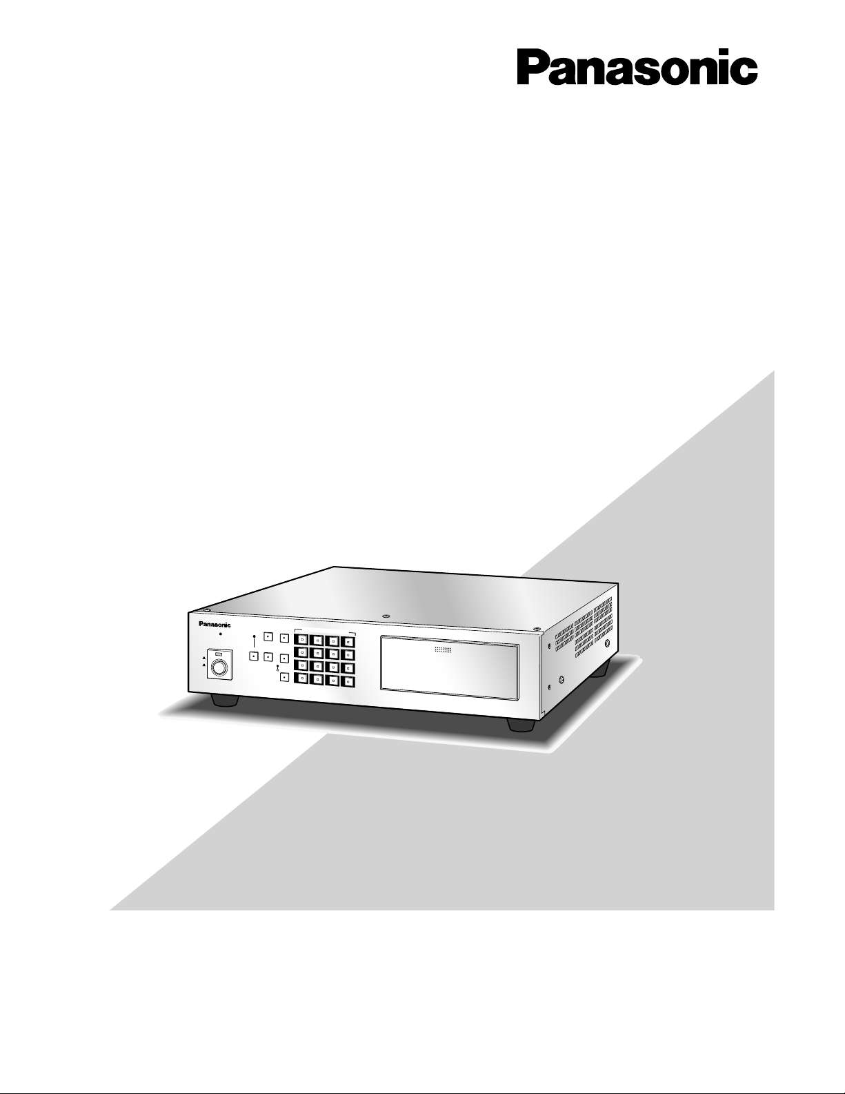
Model No. WJ-FS616C
Video Multiplexer
Operating Instructions
LOCK
MULTI
SCREEN
MULTI SCREEN
SELECT
SEQUENCE
T
ALARM
RESET
SPOT
VCR
CAM
POWER
ON
OFF
1
2
3
4
5
6
7
8
9
10
11
12
16
15
14
13
CAMERA/PRE SET POSITION
PUSH OPEN
Digital Video Multiplexer WJ-FS
616
C
2
The serial number of this product may be found on the bottom of the unit.
You should note the serial number of this unit in the space
provided and retain this book as a permanent record of your
purchase to aid identification in the event of theft.
Model No. WJ-FS616C
Serial No.
Caution:
Before attempting to connect or operate this product,
please read the label on the bottom.
NOTE: This equipment has been tested and found to comply with the limits for a Class A digital device, pursuant to
Part 15 of the FCC Rules. These limits are designed to provide reasonable protection against harmful interference
when the equipment is operated in a commercial environment. This equipment generates, uses, and can radiate
radio frequency energy and, if not installed and used in
accordance with the instruction manual, may cause harmful
interference to radio communications.
Operation of this equipment in a residential area is likely to
cause harmful interference in which case the user will be
required to correct the interference at his own expense.
FCC Caution: To assure continued compliance, (example use only shielded interface cables when connecting to computer or peripheral devices). Any changes or modifications
not expressly approved by the party responsible for compliance could void the user’s authority to operate this equipment.
For U.S.A
WARNING:
To reduce the risk of fire or electric shock, do not expose this appliance to rain or moisture.
The lightning flash with arrowhead symbol,
within an equilateral triangle, is intended to
alert the user to the presence of uninsulated
"dangerous voltage" within the product's
enclosure that may be of sufficient magnitude to constitute a risk of electric shock to
persons.
The exclamation point within an equilateral
triangle is intended to alert the user to the
presence of important operating and maintenance (servicing) instructions in the literature accompanying the appliance.
CAUTION: TO REDUCE THE RISK OF ELECTRIC SHOCK,
DO NOT REMOVE COVER (OR BACK).
NO USER-SERVICEABLE PARTS INSIDE.
REFER SERVICING TO QUALIFIED SERVICE PERSONNEL.
CAUTION
RISK OF ELECTRIC SHOCK
DO NOT OPEN
SA 1965
SA 1966

3
IMPORTANT SAFETY INSTRUCTIONS
1) Read these instructions.
2) Keep these instructions.
3) Heed all warnings.
4) Follow all instructions.
5) Do not use this apparatus near water.
6) Clean only with dry cloth.
7) Do not block any ventilation openings. Install in accordance with the manufacturer's instructions.
8) Do not use near any heat sources such as radiators, heat registers, stoves, or other apparatus (including amplifiers) that
produce heat.
9) Do not defeat the safety purpose of the polarized or grounding-type plug. A polarized plug has two blades with one wider
than the other. A grounding-type plug has two blades and a third grounding prong. The wide blade or the third prong are
provided for your safety. If the provided plug does not fit into your outlet, consult an electrician for replacement of the
obsolete outlet.
10) Protect the power cord from being walked on or pinched particularly at plugs, convenience receptacles and the points
where they exit from the apparatus.
11) Only use attachments/accessories specified by the manufacturer.
12) Use only with the cart, stand, tripod, bracket, or table specified by the manufacturer, or sold with the apparatus. When a
cart is used, use caution when moving the cart/apparatus combination to avoid injury from tip-overs.
13) Unplug this apparatus during lightning storms or when unused for long periods of time.
14) Refer all servicing to qualified service personnel. Servicing is required when the apparatus has been damaged in any way,
such as power-supply cord or plug is damaged, liquid has been spilled or objects fallen into the apparatus, the apparatus
has been exposed to rain or moisture, does not operate normally, or has been dropped.
S3125A

4
IMPORTANT SAFETY INSTRUCTIONS ............................ 3
PREFACE .......................................................................... 5
FEATURES ........................................................................ 5
PRECAUTIONS ................................................................. 6
MAJOR OPERATING CONTROLS AND
THEIR FUNCTIONS .......................................................... 7
■ Front View .................................................................. 7
■ Rear View ................................................................... 10
INSTALLATION ................................................................. 12
■ Installing the WV-PB6164 Data Multiplex Boards ...... 12
■ Tally Output Setting .................................................... 13
■ DIP Switch Setting ...................................................... 14
■ Mounting into the Rack .............................................. 15
CONNECTIONS ................................................................ 16
■ Connection with the Camera Sites ............................. 17
■ Connections for RS-485 type camera ........................ 18
■ Connection with the Monitors ..................................... 19
■ Connection with the PC .............................................. 19
■ Connection with Alarm Sensors ................................. 20
■ Connection with External Remote Control Switches .. 20
■ Connection with the Time Lapse VCR ....................... 21
MONITORS AND DISPLAYS ............................................. 22
■ Spot and Multiscreen Monitor .................................... 22
SETUP PROCEDURES .................................................... 23
SETUP MENU ................................................................... 24
■ Displaying the SETUP MENU ..................................... 24
■ Programming Setup Menu ......................................... 25
ALARM SETUP ................................................................. 26
■ Alarm Recall ............................................................... 26
■ Alarm Schedule .......................................................... 26
■ Camera Site Alarm ..................................................... 27
■ Video Loss Alarm ....................................................... 27
■ Camera Switching Pulse Loss Alarm ......................... 27
■ Alarm Display on the Monitors ................................... 27
■ Alarm Output Duration ............................................... 27
■ Alarm Buzzer Duration ............................................... 27
■ Alarm Mode on the Multiscreen Monitor .................... 28
■ Alarm Mode on the Spot Monitor ............................... 28
■ Dynamic Recording ................................................... 28
■ Alarm Recording Mode .............................................. 28
MULTISCREEN OUTPUT SETUP ...................................... 29
■ Camera Title Display .................................................. 29
■ Clock Display ............................................................ 29
■ Still Display ................................................................. 29
■ Border Display ........................................................... 29
■ Camera Display Position Setting ................................ 30
■ Sequence Mode ......................................................... 30
■ Secret View ................................................................ 30
SPOT OUTPUT SETUP ..................................................... 31
■ Camera Title Display .................................................. 31
■ Clock Display ............................................................. 31
RECORD OR MULTISCREEN 2 OUTPUT SETUP ............ 32
■ Record Output Setup ................................................. 32
■ Multiscreen 2 Output Setup ....................................... 34
SYSTEM SETUP ................................................................ 36
■ Clock Setup ................................................................ 36
■ Clock Display Position ............................................... 36
■ Camera Title Setup .................................................... 37
■ Camera Title Display Position .................................... 37
■ Sequence Setup ........................................................ 37
■ Sequence Timing (Multiscreen Monitor) .................... 40
■ Sequence Timing (Spot Monitor) ............................... 40
■ Lock Mode ................................................................. 41
■ Cable Compensation/VD2/Data ................................. 41
■ Alarm Terminal Setup ................................................. 41
■ Playback Mode .......................................................... 42
■ Data Mode ................................................................. 42
■ RS-232C Mode ........................................................... 42
■ Communication Port Setup ........................................ 42
■ VCR Input Select ........................................................ 43
■ Daisy Mode ................................................................ 43
■ Unit Address .............................................................. 43
■ Password ................................................................... 44
OTHER SETUP MENUS .................................................... 45
■ Camera Download ..................................................... 45
■ Camera Upload .......................................................... 45
■ All Reset ..................................................................... 46
OPERATING PROCEDURES........................................... 47
CONTROLLING THE VIDEO INPUT AND MONITORS ..... 48
Controlling the Spot Monitor ............................................. 48
■ Selecting the Spot Monitor ......................................... 48
■ Single Spot (Live) ....................................................... 48
■ Single Sequence (Live) .............................................. 48
Controlling the Multiscreen Monitor .................................. 49
■ Selecting the Multiscreen Monitor .............................. 49
■ Controlling the Camera Images ................................. 49
■ Controlling the Playback Images ............................... 51
■ Displaying the Camera and Playback Images .......... 54
CAMERA CONTROL FUNCTION ..................................... 56
■ Camera Selection ....................................................... 56
■ Controlling Camera Site Accessories .........................56
ALARM CONTROL FUNCTION ........................................ 59
■ Alarm Input ................................................................. 59
■ Alarm Operation ......................................................... 59
■ Alarm Reset ................................................................ 61
■ Example of Using Multiscreen 2 Monitor ................... 61
■ Alarm Suspension ...................................................... 62
OTHER FUNCTION ........................................................... 63
■ Recording on the Time Lapse VCR ........................... 63
■ Camera Switching Pulse Loss Display ...................... 63
OPERATING PROCEDURES (with WV-CU550C) .......... 65
SYSTEM CONTROLLER WV-CU550C .............................. 66
■ Major Operating Controls and Their Functions .......... 66
■ Installations ................................................................ 68
SETUP MENU OPERATIONS (WITH WV-CU550C) .......... 70
FUNCTION OPERATIONS (WITH WV-CU550C) .............. 71
Controlling the Video Input and Monitors ......................... 71
Camera Control Function .................................................. 71
■ Camera Selection ....................................................... 72
■ Controlling Camera Site Accessories ........................ 72
Alarm Control Function ..................................................... 74
■ Alarm Suspension ...................................................... 74
SYSTEM EXPANSION ....................................................... 75
■ Connections ............................................................... 76
■ Operating Procedure ................................................. 76
■ Other Applications ..................................................... 76
APPENDIX ......................................................................... 78
STANDARD ACCESSORIES ............................................. 82
SPECIFICATIONS.............................................................. 82
CONTENTS

5
PREF ACE
The WJ-FS616C Video Multiplexer is designed to multiplex
the field signals from video cameras and record the camera
images on a time lapse VCR.
Up to 16 cameras can be connected to the unit for monitoring images in multiscreen, sequence, freeze or electronic
zoom mode on a video monitor screen.
The WJ-FS616C Video Multiplexer allows you to control
camera functions such as lens focussing, zooming, and iris,
positioning of the pan/tilt head, etc. This makes the system
highly flexible and sophisticated, and allows expansion to
up to 64 cameras.
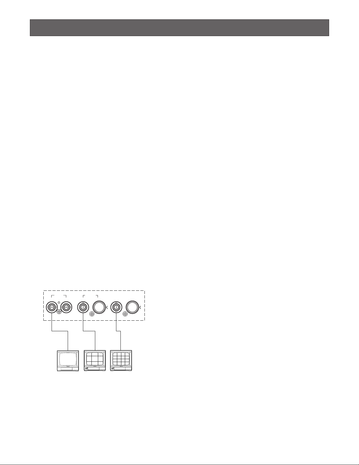
FEATURES
• The images of any connected camera can be displayed
on full screen or on a 4, 7, 9, 10, 13 and 16 multiscreen
as shown below.
(7, 10 and 13 multiscreens are not available for playback images.)
In addition, one playback image can be displayed with
camera images in 4, 7, 10 and 13 multiscreens.
• The pattern of a spot sequence consisting of up to 32
steps can be programmed by presetting the channel
order and individual dwell time.
The pattern of a 4, 7, 9, 10, 13, or 16 multiscreen
sequence consisting of up to 5 steps can be programmed as shown below.
• Electronic zoom and freeze image functions are available. The zoom area can be selected with the direction
buttons.
• Up to 16 camera images multiplexed by the field rate
are available at the REC OUT connector for recording
on the time lapse VCR. Alarm priority recording is supported.
• Camera functions such as pan/tilt, lens zoom, focus
and iris, and camera setup can be controlled via a
coaxial cable or RS-485 interface.
• The WJ-FS616C has a versatile alarm mode to optimize
its multiscreen output, spot output, and record output.
• REC, PLAY, REW, FF, etc. can be controlled from the
front panel of the video multiplexer, via the RS-232C
interface or the wired remote control terminal of the
Panasonic Time Lapse VCR.
• The WJ-FS616C can be controlled from a PC or the WVCU550C and WV-CU360C System Controller via RS232C or RS-485 interface.
4-SEGMENT
SCREEN
7-SEGMENT
SCREEN
9-SEGMENT
SCREEN
10-SEGMENT
SCREEN
13-SEGMENT
SCREEN
16-SEGMENT
SCREEN
2 sec2 sec 5 sec 3 sec 1 sec
4 sec

6
PRECAUTIONS
• Refer all work related to the installation of this
product to qualified service personnel or system
installers.
• Do not block the ventilation opening or slots on the
cover.
To prevent the appliance from overheating, place it at
least 5 cm (2 inches) away from the wall.
• Do not drop metallic parts through slots.
This could permanently damage the appliance. Turn
the power off immediately and contact qualified service
personnel for service.
• Do not attempt to disassemble the appliance.
To prevent electric shock, do not remove screws or
covers.
There are no user-serviceable parts inside. Contact
qualified service personnel for maintenance.
• Handle the appliance with care.
Do not strike or shake, as this may damage the appliance.
• Do not expose the appliance to water or moisture,
nor try to operate it in wet areas.
Take immediate action if the appliance becomes wet.
Turn the power off and refer servicing to qualified service personnel. Moisture can damage the appliance
and also cause electric shock.
• Do not use strong or abrasive detergents when
cleaning the appliance body.
Use a dry cloth to clean the appliance when it is dirty.
When the dirt is hard to remove, use a mild detergent
and wipe gently.
• Do not operate the appliance beyond its specified
temperature, humidity or power source ratings.
Use the appliance at temperatures within –10˚C - +50˚C
(14˚F – 122˚F) and humidity below 90 %.
The input power source for this appliance is 120 V AC
60 Hz.
• Fully charge up the backup battery.
Keep the appliance turned on for at least 48 hours to
recharge the backup battery. This procedure is necessary when using the appliance for the first time or after
it has been unplugged for a long time from the AC outlet. Insufficient charging of the battery may cause erasure of settings if the AC power supply should fail. The
battery, if fully charged, will back up the settings for 72
hours in an ordinary environment.
• We recommend that you note down your settings
and retain them. Power or battery failure may erase
settings you entered.
7
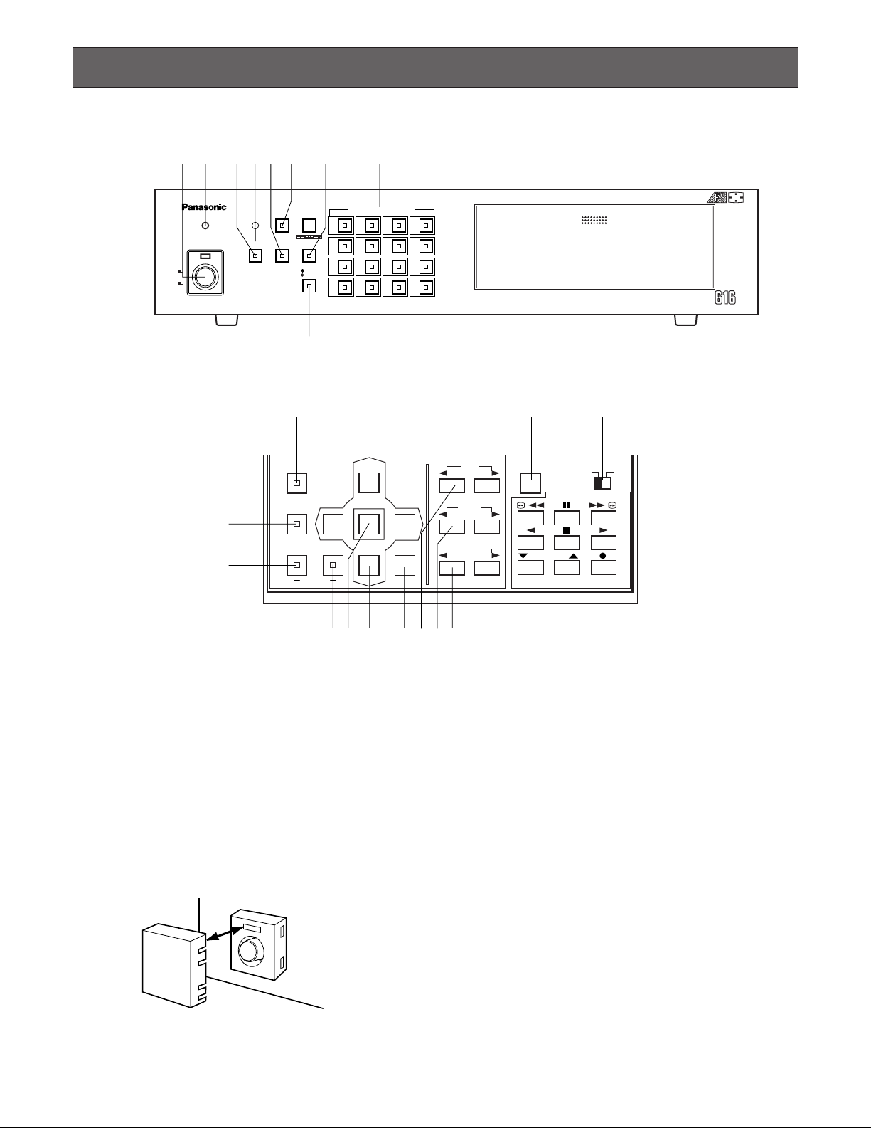
MAJOR OPERATING CONTROLS AND THEIR FUNCTIONS
■ Front View
FUNCTION
PRE-POSI
LEFT
RIGHT
AUTO
UP
DOWN
HOME/SET
EL-ZOOM
STILL
CURSOR / CAMERA CONTOROL
CLOSE
OPEN
IRIS
NEAR FAR
FOCUS
TELE
WIDE
ZOOM
LOCK
OFF ON
SET UP/ESC
VCR CONTROL
T/L MODE
/ /
4
8
12
16
3
7
11
15
2
6
10
14
1
5
9
13
PUSH OPEN
16
POWER
LOCK
ON
OFF
ALARM
MULTI
SCREEN
MULTISCREEN
SELECT
RESET SPOT SEQUENCE
VCR
CAM
CAMERA/PRESET POSITION
Digital Video Multiplexer WJ-FS C
qw ertyui o !1
!0
@1 #1 #2
@2
@3
@4@5 @6 @7 @8 @9#0 #3
q Power Switch (POWER ON/OFF)
This switch turns the power of the video multiplexer on
or off. The indicator lights while the power is turned on.
Caution: The indicator blinks to indicate raising tem-
perature in the video multiplexer.
Turn the power off and refer servicing to qualified
service personnel.
Note: To prevent accidental interruption of power sup-
ply to the video multiplexer, cover the power switch
with the supplied switch protector as shown in the
figure.
w Lock Indicator (LOCK)
This indicator (Yellow) lights to indicate that the LOCK
switch is in ON position.
While this indicator is on, control from the video multiplexer is disabled.
e Alarm Reset Button (RESET)
This button is used to cancel an activated alarm.
Press this button, while the alarm function is activated,
to reset the alarm and return the system to the condition
before the alarm function was activated.
The indicator (Orange) in the button lights to indicate
that the alarm suspension mode is selected.
r Alarm Indicator (ALARM)
This indicator (Red) blinks to indicate an alarm condition exists.
It changes to steady light when the alarm is reset automatically.
To turn the indicator off, press the ALARM RESET button.
SWITCH
PROTECTOR

8
t Spot Monitor Button (SPOT)
This button is used to operate the spot monitor connected to the SPOT OUT connector on the rear of the video
multiplexer.
The indicator (Green) in the button lights to indicate that
the spot monitor is selected, and enables control of the
monitor.
y Multiscreen Monitor Button (MULTISCREEN)
This button is used to operate the multiscreen monitor
connected to the MULTISCREEN OUT connector on the
rear of the video multiplexer.
The indicator (Green) in the button lights to indicate that
the multiscreen monitor is selected, and enables control
of the monitor.
Note: When the monitor is connected to the REC OUT
connector for using as Multiscreen 2 Output, this
button alternately selects multiscreen output or multiscreen 2 output.
The indicator blinks to indicate that the multiscreen
2 output is selected.
u Multiscreen Selection Button (MULTISCREEN
SELECT)
This button is used to select the multiscreen pattern to
be displayed on the multiscreen monitor while monitoring the camera images or VCR playback images.
Pressing this button will toggle the screen pattern as
follows:
Camera Images:
4→7→9→10→13→16→4 screen segments
VCR Playback Images:
4→9→16→4 screen segments
i Sequence Button (SEQUENCE)
This button is used to activate the sequence mode. In
this mode, a series of camera images is displayed in
succession on the monitor screen for the specified
duration.
The indicator (Green) in the button lights to indicate that
this mode is selected.
o Camera Number Buttons (CAMERA)
Preset Position Number Buttons
(PRESET POSITION)
CAMERA:
These buttons select the camera images corresponding to the button.
The indicator (Green) in the button lights to indicate
the camera number currently selected.
PRESET POSITION:
These buttons are used in combination with the PRE
POSI button to assign a preset position number to
the selected camera.
!0 VCR/Camera Selection Button (VCR/CAM)
This button is used to select the camera image or VCR
playback image to be displayed on the multiscreen
monitor screen.
The indicator (Green) in the button lights to indicate that
the VCR mode is selected.
Note: The above operation is not valid unless multi-
screen output is selected by pressing the MULTISCREEN button.
!1 Control Panel
Press “PUSH OPEN” panel to open the control panel.
@1 Function Button (FUNCTION)
This button is used to display the camera images with a
VCR playback image on the multiscreen monitor.
While displaying the setup menu on the monitor, pressing this button will select the next page of the setup
menu.
@2 Preset Position Button (PRE-POSI)
This button is used to assign a preset position to a
specified camera.
@3 Still Button (STILL)
Decrement Button (–)
This button is used to freeze the image currently displayed on the multiscreen monitor.
The indicator (Green) in the button lights to indicate that
the freeze mode is selected.
While displaying the setup menu on the monitor, pressing this button will select the parameter reversely in the
setup menu.
@4 Electronic Zoom Button (EL-ZOOM)
Increment Button (+)
This button is used to zoom the image currently displayed on the multiscreen monitor.
The indicator (Green) in the button lights to indicate that
the zoom mode is selected.
While displaying the setup menu on the monitor, pressing this button will select the parameter forwardly in the
setup menu.
@5 Home/Set Button (HOME/SET)
This button is used to return to the home position of the
camera.
While displaying the setup menu on the monitor, pressing this button will execute the currently highlighted
selection and to enter a submenu in the setup menu if
the item has its own setting menu.

9
@6 Direction Buttons (UP/DOWN/LEFT/RIGHT)
These buttons are used to manually operate the Pan/Tilt
Head, move the cursor position in the setup menu of
the video multiplexer, or to select an area for Electric
Zooming.
UP: Upward
DOWN: Downward
LEFT: Left
RIGHT: Right
@7 Auto Button (AUTO)
This button is used to activate the auto panning function
if the camera is equipped with the specific future.
@8 Iris Buttons (IRIS, CLOSE/OPEN)
Close or open the lens iris of cameras equipped with
the specified lens.
When these buttons are pressed at the same time, the
lens iris is reset to the factory default settings.
@9 Focus Buttons (FOCUS, NEAR/FAR)
Adjusts the lens focus of cameras equipped with the
specified lens.
When these buttons are pressed at the same time, the
lens focus is automatically set if the camera is
equipped with the specific future.
#0 Zoom Buttons (ZOOM, TELE/WIDE)
Adjusts the lens zoom of cameras equipped with the
specified lens.
#1 Setup/Escape Button (SET UP/ESC)
This button is used in the video multiplexer’s setup
operation. Pressing this button for two seconds or more
will open or close the video multiplexer’s setup menu on
the monitor screen.
While the setup menu is displayed on the monitor
screen, press this button to execute the currently
selected setting and return to the previous setup menu.
#2Lock Switch (LOCK OFF/ON)
This switch can be used to lock out operation of the
video multiplexer panel controls.
While this switch is in ON position, control from the
video multiplexer is disabled.
#3 VCR Control Buttons
These buttons are used for remote control of the VCR
that is connected to the video multiplexer.
The buttons function as shown below.
: Rewind
: Pause
: Fast Forward
: Reverse Play
: Stop
: Play
: Decreases recording duration
: Increases recording duration
: Record
/
/
10
$1 Camera Output Connectors (CAMERA OUT)
The video signal connected to the CAMERA IN connector is looped through to this connector with an automatic 75 Ω termination.
The camera control signal multiplexed on the video signal is not available at this connector. When the power
switch of the video multiplexer is turned off, no signal is
present at this connector.
$22 Camera Input Connectors (CAMERA IN)
These connectors accept either a color or B/W composite video signal from the cameras. In addition, the VD2
signal for synchronizing the vertical timing of the cameras, and data to control camera site devices are multiplexed through these connectors.
$3 RS485 Terminal (RS485)
This terminal is used to exchange control data with the
camera site.
$4 Line Termination Switch (TERM., OFF/ON)
This switch is used to enable termination of the RS485
terminal.
$5 Line Selection Switch (LINE SELECT, 2/4)
This switch lets you select either Full Duplex (4 lines) or
Half Duplex (2 lines) for the communication lines.
$6 Camera Switching Input Connector
(CAMERA SW IN)
The camera switching pulse from the time lapse VCR is
supplied to this connector.
The camera switching interval (Sequential Dwell Time)
can be synchronized with the time lapse mode set in
the associated time lapse VCR.
$7 Gen-Lock Input Connector (GENLOCK IN (VS))
The Gen-Lock signal can be supplied to this connector
for synchronizing the system.
$8 Spot Input/Output Connectors (SPOT, OUT/IN)
IN: This connector accepts the video output signal from
the external system.
The supplied video can be displayed on the spot
monitor screen with the specified conditions.
OUT: This connector supplies the video output signal
for the spot monitor.
$9 Record Output Connectors
(REC OUT, VIDEO/S-VIDEO)
The recording signal for the time lapse VCR is provided
via these connectors.
These connectors can also be used as multiscreen 2
output with the specified conditions.
%0 Playback Input Connectors
(PLAY IN, VIDEO/S-VIDEO)
The playback signal from the time lapse VCR is supplied to these connectors.
%1 Multiscreen Output Connectors
( MULTISCREEN OUT, VIDEO/S-VIDEO)
The video output signal for the multiscreen monitor is
provided via these connectors
%2 RS-232C Port (VCR CONTROL, RS-232C)
The VCR control signal for the time lapse VCR is provided via this connector.
Connecting a PC to this connector will allow you to
remote control the video multiplexer.
%3 Remote Output Connector
(VCR CONTROL, REMOTE OUT)
The VCR control signal for the time lapse VCR is provided via this connector.
You can select in the setup menu whether to have the
VCR control signal supplied from this connector or the
RS-232C Port.
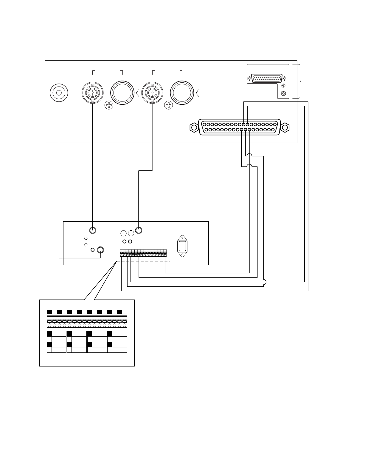
%4 Alarm/Remote Port (ALARM/REMOTE)
This connector accepts the alarm signals from the
associated alarm contacts and the control signals from
the external system.
%5 Power Cord
■ Rear View
16 15 14 13 12 11111098765432 1
16 15 14
13 12
1098765
43
21
A BTA B
R
G
N
D
G
N
D
RS485 TERM.
LINE
SELECT
CAMERA
SW IN
GENLOCK
IN (VS)
OFF ON 2 4
SPOT
REC OUT
PLAY IN
MULTISCREEN OUT
VCR CONTROL
RS–232C
OUT I N
VIDEO S–VIDEO S–VIDEO
S–VIDEOVIDEO
VIDEO
REMOTE
ALARM/REMOTE
OUT
TERM.
OFF
INOUT
ON
SIGNAL
GND
DATA
CAMERA
IN
CAMERA
OUT
$1
$2
$3 $4 $5 $6 $7 $8 $9 %0 %1 %2
%3
%4
%5%6%7%8

11
%6 Signal Ground Terminal (SIGNAL GND)
%7 Data Termination Switch
(TERM., OFF/ON)
This switch is used to enable termination of the video
multiplexer’s data port.
%8 Data Port (DATA, OUT/IN)
These ports are used to exchange control data with the
specified system controller or a PC in a system.
12
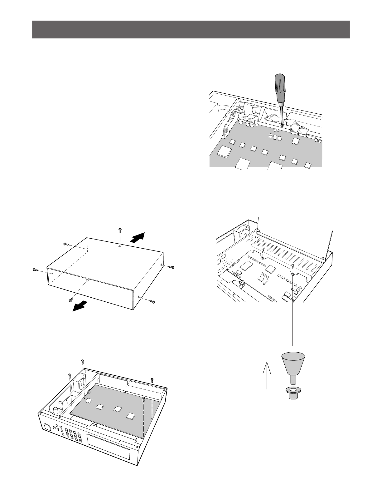
4. Remove the one screw shown below. Then turn over the
printed circuit board with the front side up.
5. Pull the two knobs out from the bracket shown in the figure. Then remove the bracket.
INSTALLATION
The installations described below should be made by
the qualified service personnel or system installers.
■ Installing the WV-PB6164 Data
Multiplex Boards
When controlling the camera with the multiplexed control
data by connecting a coaxial cable, the WV-PB6164 Data
Multiplex Board must be installed in the video multiplexer.
Four data multiplex boards are included with the WJFS616C for cameras 1 to 4.
Please note that additional multiplex boards are available
for purchase as model WV-PB6164 Data Multiplex Boards,
which includes four control boards.
Caution: Before installing boards, be sure to turn off the
power switch of the video multiplexer.
1. Remove the six screws on the top cover of the video
multiplexer as shown in the figure.
2. Remove the top cover.
3. Remove the four screws on the board as shown in the
figure.
Front
Rear
13
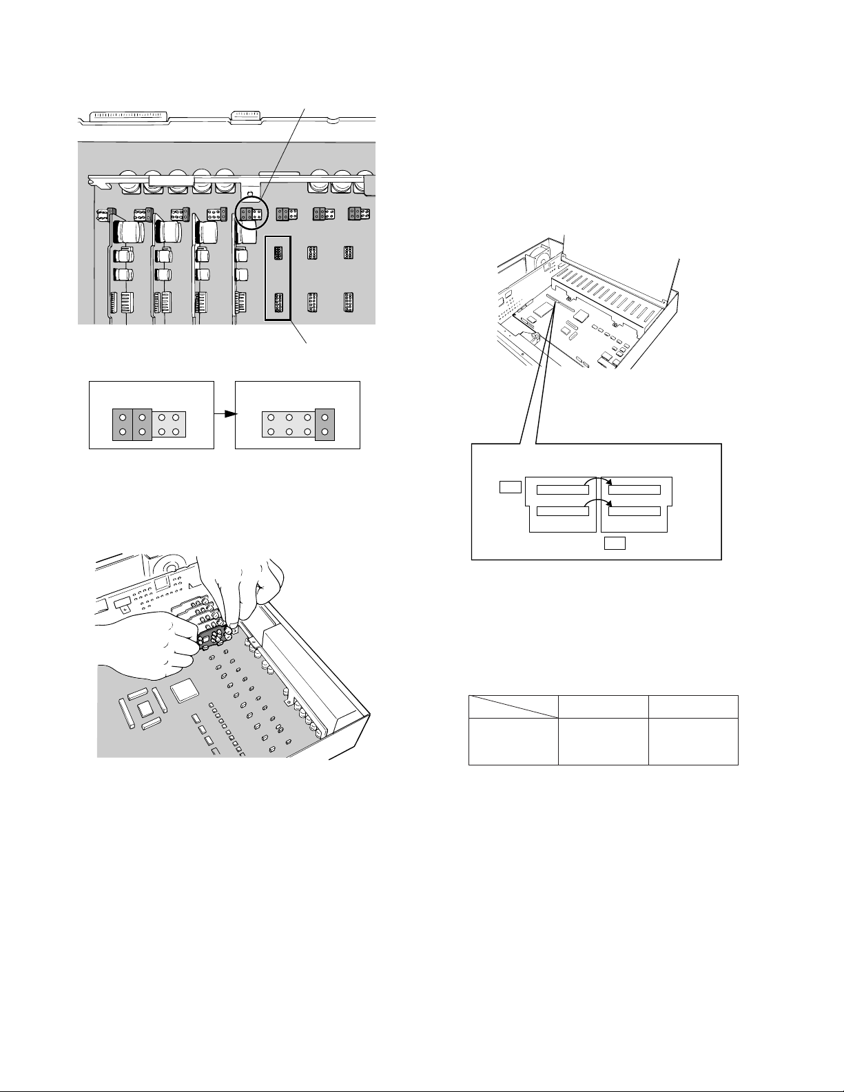
■ Tally Output Setting
Allows you to use the Alarm Input terminal on the
ALARM/REMOTE port as Tally Output terminal by
changing two internal connections.
It is enabled use that mingles alarm input and tally output.
1. Disassemble the video multiplexer as described for
installing the Data Multiplex Boards on page 12.
2. Move the two connectors from the ALM side to the TLY
side as shown above.
The relation between the connector numbers and channel numbers is shown in the table below.
6. Set the jumper connector, that is located at the top left
of the board, to the position shown below where the
board is installed.
7. Insert the board in the board connector. Confirm that
the position is correct and it is placed firmly.
8. After installing the boards, secure them by tightening
the screws and knobs shown above.
Note: Some settings for the VD2 signal and control data
will be necessary from the setup menu of the video
multiplexer.
Refer to Cable Compensation/VD2/Data Setup on
page 41 for details.
Jumper Connector
Board Connector
CH9 - CH16
CH1 - CH8
Alarm Input
CN33
CN32
Tally Output
CN37
CN36
Initial State Installed State
2
8
2
8
1
7
1
7
ALM
CN33
10 1
CN32
91
CN37
10 1
CN36
91
TLY
14
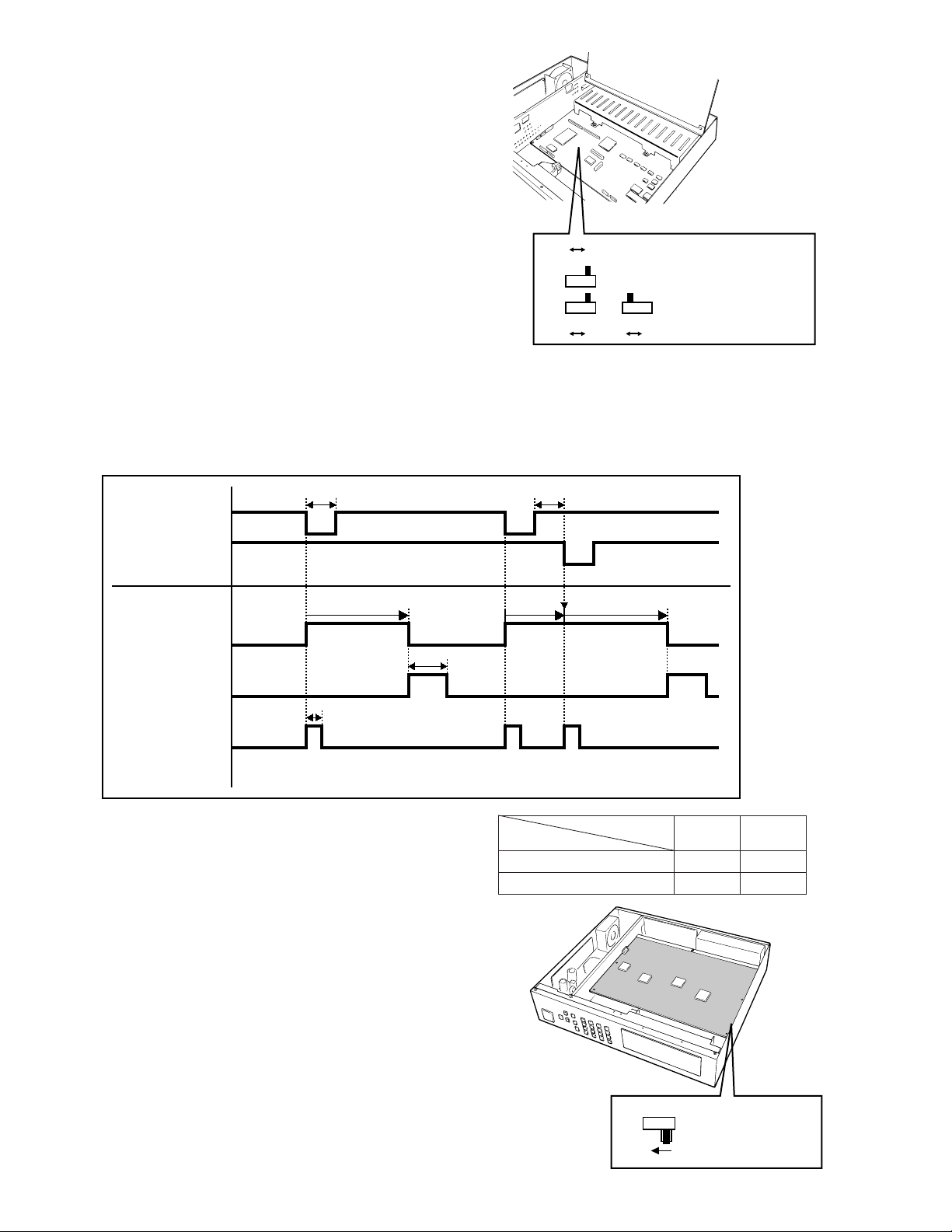
C If another alarm is received before the existing alarm is
reset, the alarm output lasts as long as the duration set
for the succeeding alarm.
• The O.C position of SW3, SW4, and SW5 corresponds
to their 0/5 V position as shown in the table.
● Dummy Black Image Setting
According to the factory default setting, the Dummy
Black Image signal is supplied to the REC OUT connector as needed to overwrite any image displayed by
error. If this function is not required, set the switch SW
1 to the position shown below.
1. Disassemble the video multiplexer as described for
installing the Data Multiplex Boards on page 12.
2. Set switch (SW1) on the board to the position shown in
the figure.
■ DIP Switch Setting
● Alarm Output Setting
The following settings let you set the polarities of alarm output, alarm reset output, and alarm & SW output on the
ALARM/REMOTE port.
1. Disassemble the video multiplexer as described for
installing the Data Multiplex Boards on page 12.
2. Set switches (SW3/SW4/SW5) on the board to the
required position either Open Collector (O.C) or Pulse
(0/5V) for alarm control signals.
Open Collector (O.C): 16V DC 100 mA max.
Pulse (0/5V): +5V DC approx. 500 ms
The positions in the figure are the factory default setting.
• Timing Table of the signals (0/5 V settings)
0/5V O.C
SW5
0/5V 0/5V
SW3
O.C
SW4
O.C
SW3 : Alarm Output
SW4 : Alarm Reset Output
SW5 : Alarm & SW Output
0VHi-Z Hi-Z Hi-Z
100 ms or more
Approx 100 ms
Approx.
450 ms
Alarm output time
0V
Alarm output time
C
Hi-ZHi-Z 0V
100 ms or more
Retrigger
5V
Alarm output
(Pin #9)
Alarm input 1
Alarm input 2
0V
5V
Alarm reset
output (Pin #27)
0V
5V
Alarm & SW
Output (Pin #25)
0V
SW1
OFF
SW1 : Record Output
O.C position
0/5 V position
Terminal condition
SW
OFF
Hi-Z
0 V
ON
0 V
5 V
15
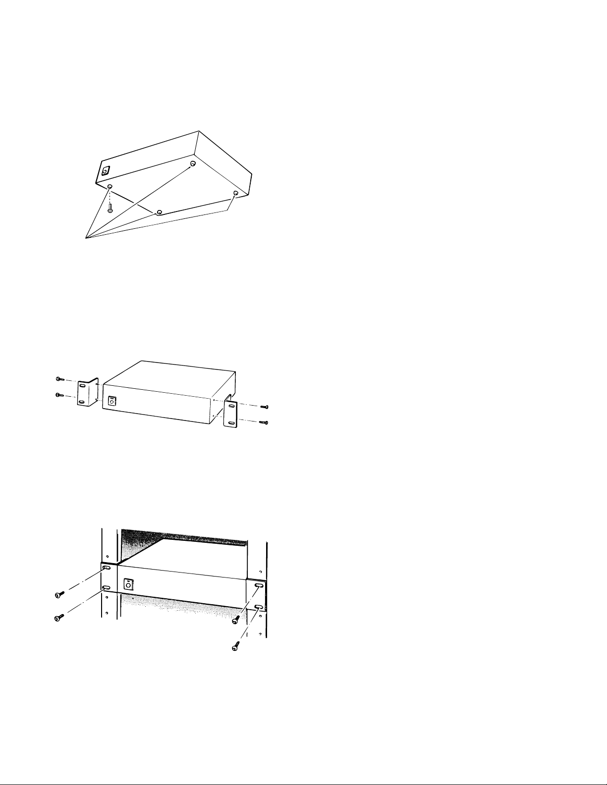
■ Mounting into the Rack
The video multiplexer can be mounted into the rack as
described below.
1. Remove the four rubber feet by removing the four
screws on the bottom of the video multiplexer.
2. Place the rack mounting brackets on both sides of the
video multiplexer and tighten with the four supplied
screws (M4 X10).
3. Install the video multiplexer with the rack mounting
brackets in the rack securing it with four screws (procured locally).
Cautions:
• The cooling fan inside the video multiplexer is subject to wear and needs to be replaced periodically.
• Do not block the ventilation opening or slots on the
cover to prevent the appliance from overheating.
Always keep the temperature in the rack within 45˚C
(113˚F).
• If the rack is subject to vibration, secure the rear of
the appliance to the rack by using additional mounting brackets (procured locally).
16
CONNECTIONS
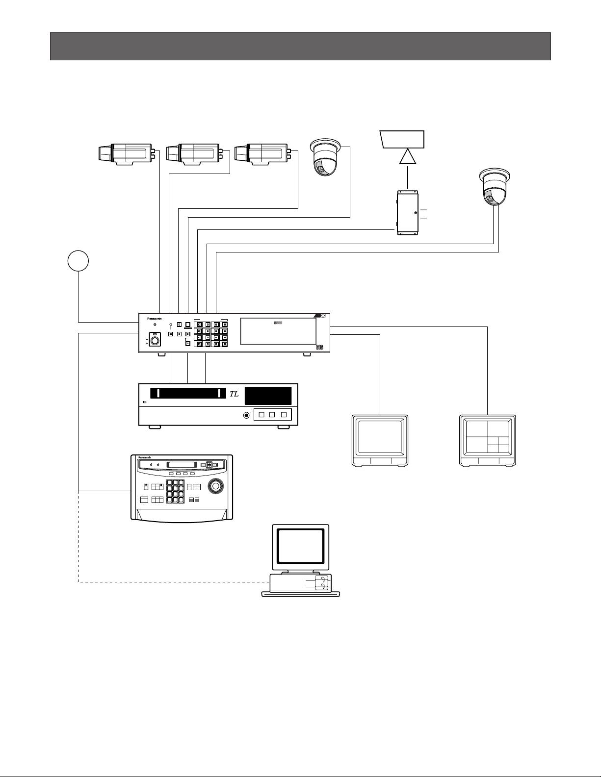
Shown below is an example of a basic system connection.
Basic System Connection
Video
Data RS-485
Video Multiplexer
WJ-FS616C
Time Lapse VCR
Personal Computer
(Software)
System Controller
WV-CU550C
Spot Monitor
Live 1-16ch
Multiscreen Monitor
Live 1-16ch
Playback 1-16ch
RS-232C/Wired
Alarm Sensor
AUX
Alarm
4
8
12
16
3
7
11
15
2
6
10
14
1
5
9
13
PUSH OPEN
16
POWER
LOCK
ON
OFF
ALARM
MULTI
SCREEN
MULTISCREEN
SELECT
RESET SPOT SEQUENCE
VCR
CAM
CAMERA/PRESET POSITION
Digital Video Multiplexer WJ-FS C
1 2 3
4 5 6
7 8 9
MON CAM
ESC SET
0
ACK
RESET
BACK
SEQ
FORWARD
SEQ ALT
DEC
-1CAM
INC
+1CAM
STOP12
AUX
CLOSE
OPEN
IRIS
PRESET
FOCUS
NEAR
ZOOM
TELE
FAR
WIDE
System Controller WV-CU616
LEFT
RIGHT
UP
DOWN
ALARM BUSY
F3 F4F2F1
AF
17
For cameras equipped with RS-485 communication
facility, connect the RS-485 cable as follows.
Note: If you use cables assembled from locally pro-
cured materials, it is important that only high quality,
data grade cable, suitable for RS-485 communication (shielded 2-wire twisted pair cable) is used,
BELDEN 9406 or equivalent.
Low grade cable will result in unstable operation of
the system.
Check the settings of the camera addresses when
using cameras capable of RS-485 communication.
Operations from the multiplexer will not work if the camera addresses are set improperly.
• Do not use addresses other than 1 through 16 for
individual cameras (“17” is not allowed.)
• Do not set the same address for more than one
camera in an RS-485 chain.
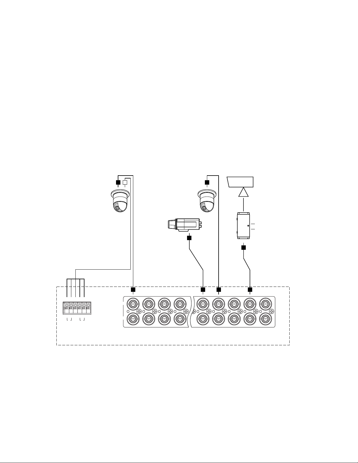
■ Connection with the Camera Sites
Connect cameras (or camera site equipment) data multiplexed type to the CAMERA IN connectors 1 through 4
on the rear of the video multiplexer.
Note: Make sure that the cable length between the
camera site and the WJ-FS616C video multiplexer
is less than 900 m (3 000 ft) when using RG-59/U,
BELDEN 9259 or equivalent cables.
Connect none multiplexed type cameras to the CAMERA IN connectors 5 through 16.
Note: If you need to change input channels from the
none multiplexed type to multiplexed, install the
WV-PB6164 Data Multiplex Boards for the corresponding channels inside the video multiplexer. For
installations, see page 12.
CAMERA
IN
CAMERA
OUT
16 15 14 13 5 4 3 2 1
16 15 14 13 5 4 3 2 1
A BTA B
R
G
N
D
G
N
D
RS485
AUX
Alarm
Video Multiplexer WJ-FS616C

18
■ Connections for RS-485 type camera
There are two options to connect the camera with the
multiplexer, depending on the distance between them.
For data multiplexed type cameras, a maximum distance of 900 meters (3 000 ft) is the limit for using coaxial cable such as RG-59/U, BELDEN 9259 or equivalent.
If more distance is required, use cameras and multiplexer with RS-485 communication feature. This will
lower signal loss and extend the distance as video signal and data are transmitted separately.
Note that you need to set up the communication port as
described on page 42 when using the RS-485 feature.
Note: Recommended for RS-485 communication is
shielded, two-wire, twisted pair, low impedance
cable, AWG#22 or thicker.
(1) Connect with a RS-485 camera in “Home Run” wiring as
shown below, then set the LINE SELECT switch to “2” or
“4”.
(2) Connect cameras in a Daisy Chain
1. Draw up a plan for connection between the cameras
and the input channels of the video multiplexer, and the
assignment of unit addresses to cameras.
Cautions:
Check the settings of the camera addresses when
using cameras capable of RS-485 communication.
Operations from the multiplexer will not work if the camera addresses are set improperly.
• Do not use addresses other than 1 through 16 for
individual cameras (“17” is not allowed).
• Do not set a single address for more than one camera in an RS-485 chain.
2. Set the LINE SELECT switch of the multiplexer to “2”.
Also set the switch of the connected equipment if
required.
3. Connect one end of the cable as shown to the RS-485
terminal of the multiplexer, and the other end to the first
camera in the chain. Repeat this procedure for all cameras to the end of the chain.
4. Set the termination switches of the multiplexer and cameras at both ends of the chain to ON position.
Termination switches of cameras not at the chain ends
must be in OFF position.
Cautions:
• Termination is the key to data transmission and
reception in the chain. Only the switches at the
chain ends must be set to ON, while the other
switches are set to OFF.
• Response may slow gradually the higher the equipment number in the chain.
WV-RM70 and others
TERM
OFF
ON
DATA
T(A) T(B) R(A) R(B)
GND
RS485 TERM.
A BTA B
G
N
D
R
(A)
(B)
GND
G
N
D
OFF ON
WV-CPR450 and others (For the
Termination Switch positions, refer
to the instruction manual for the
camera.)
RS485 TERM.
A BTA B
G
N
D
G
N
R
D
LINE
SELECT
OFF ON 2 4
WJ-FS616C
LINE
SELECT
OFF ON 2 4
WJ-FS616C
The switch on a daisychain-connected unit not
at the extremities must
be in the OFF position.
(A)
OFF ON
(B)
GND
RS485 TERM.
A BTA B
G
N
D
G
N
R
D
The switch on the end
unit should be in the
ON position.
(A)
OFF ON
(B)
GND
WV-CPR450 and others
(For the Termination
Switch positions, refer
to the instruction
manual for the
corresponding unit.)
LINE
SELECT
OFF ON 2 4
WJ-FS616C
Set it to
position 2
19
DATA port
• In page 2 of 2 of the SYSTEM SETUP menu, set the
DATA MODE to PC and press the [SET UP/ESC] button
to activate the DATA port on the rear panel.
Then you need to select the parameters of the DATA in
the COM PORT SETUP menu detailed on page 42.
• Use a 6-core modular cable to connect the multiplexer
with the PC.
Caution: Data disruption may occur if you use both
DATA port and RS-232C port at a time. Use only
one port to communicate with the PC.
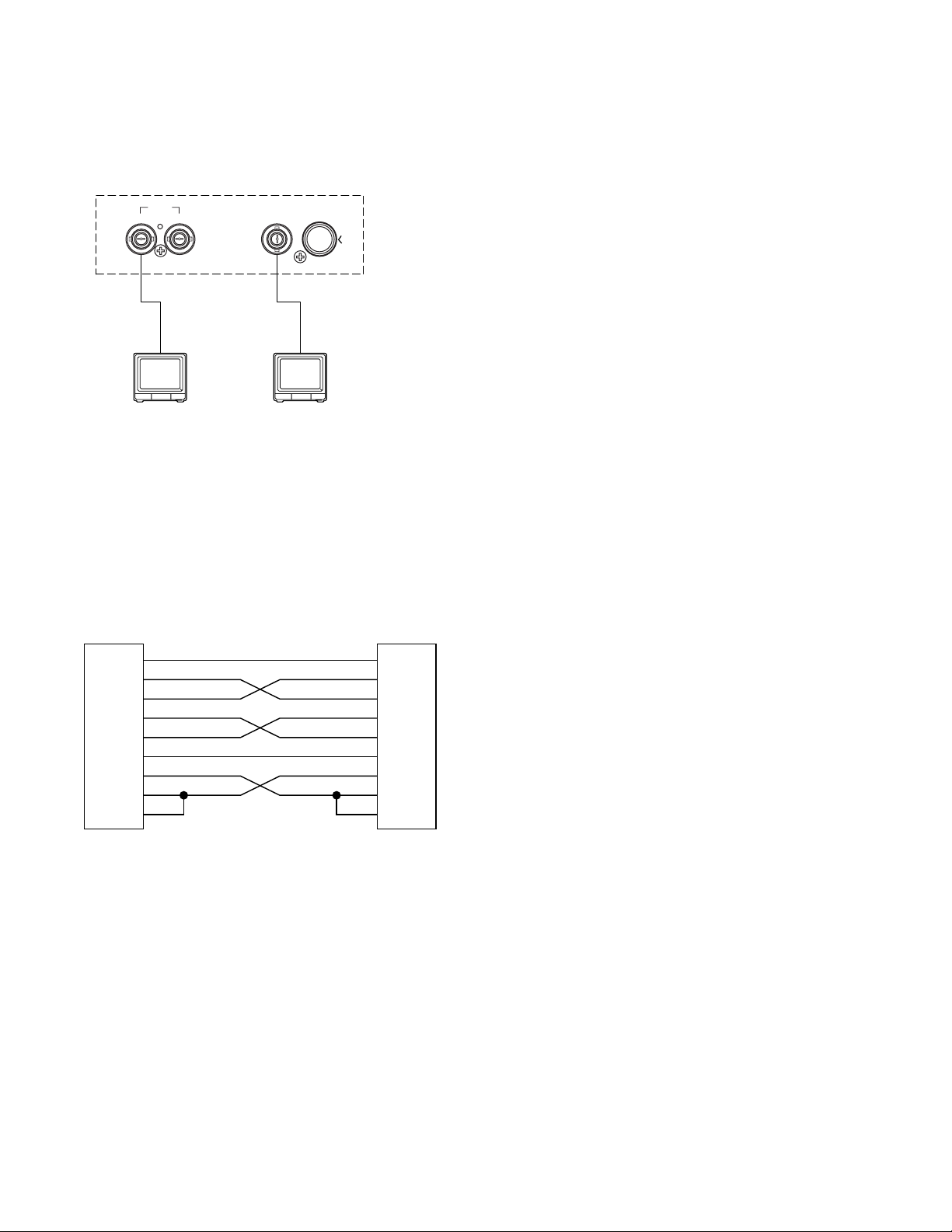
■ Connection with the Monitors
Connect the Monitors to the SPOT OUT connector and
MULTISCREEN OUT connector on the rear of the video
multiplexer with the coaxial cable.
■ Connection with the PC
There are two options to communicate with the PC, the
first is using RS-232C port and the second is via DATA
port.
RS-232C
• In page 2 of 2 of the SYSTEM SETUP menu, set the RS232C MODE to PC and press the [SET UP/ESC] button
to activate the RS-232C port on the rear panel.
Then you need to select the parameters of the RS-232C
in the COM PORT SETUP menu detailed on page 42.
• Use a cross type RS-232C cable to connect the multiplexer with the PC.
Video Multiplexer
WJ-FS616C
SPOT
OUT I N
MULTISCREEN OUT
S–VIDEOVIDEO
1
FG
SG
2
3
4
5
7
20
6
8
TxD
RxD
RTS
CTS
DTR
DSR
DCD
PC
1
FG
2
TxD
3
RxD
4
RTS
5
CTS
7
SG
20
DTR
6
DSR
8
DCD
FS616C end
20
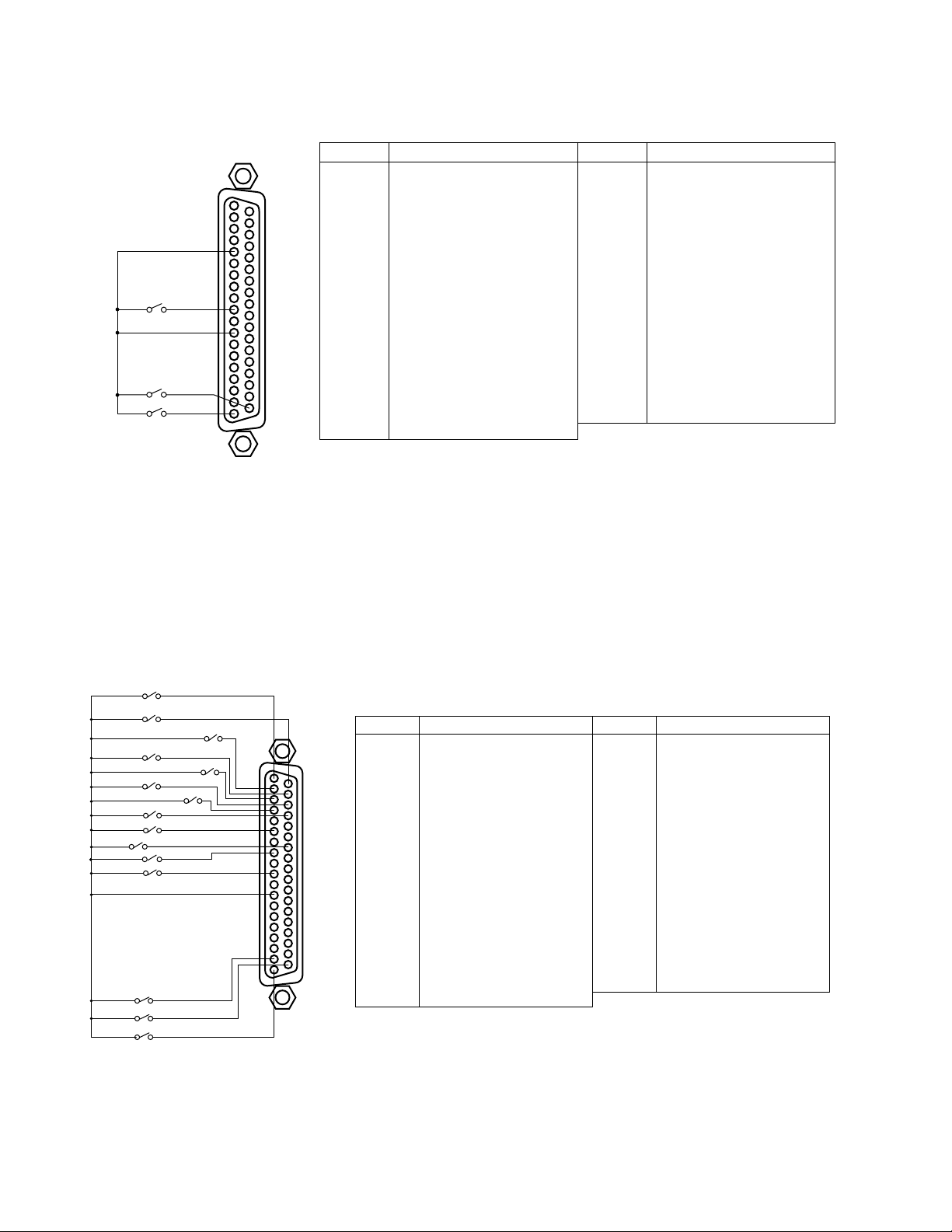
■ Connection with Alarm Sensors
Connect the sensor switches to the ALARM/REMOTE port on the rear of the video multiplexer as shown in the example
below.
Notes:
• Alarm inputs simultaneously or at very short intervals will be ignored. Allow for an interval of at least 100 ms from one
alarm input to the next.
• Connect Pin#5, Alarm/Remote Select Input to Pin#12, GND.
■ Connection with External Remote Control Switches
Connect the switches (dry contact or open collector input) to the ALARM/REMOTE port on the rear of the video multiplexer
as shown in the example below.
Notes:
• Pin#6, Sequence SW for Spot Output and the Pin#8, Alarm Recover Input can also accept DC voltages of 5 V (high
level) and 0 V (low level) besides the switch contact signals.
The multiplexer recognizes falling edge (high to low transition) as an input.
• Pin#5, Alarm/Remote Select Input must be open.
GND
SW16
SW2
SW1
ALARM/REMOTE
1
19
20
37
Pin No. Designation
1
Function
2
Electronic Zoom
3
Sequence
4
Spot
5
Alarm/Remote Select Input
6
Sequence SW for Spot Output
7
Not Used
8
Alarm Recover Input
9
Alarm Output
10
Alarm 16
11
Alarm 14
12
Ground
13
Alarm 11
14
Alarm 9
15
Alarm 8
16
Alarm 6
17
Ground
18
Alarm 3
19
Alarm 1
Pin No. Designation
20
Still Picture
21
VCR/Camera Select
22
Multiscreen Select
23
Multiscreen
24
Ground
25
Alarm & SW Output
26
Time Adjust Input
27
Alarm Reset Output
28
Ground
29
Alarm 15
30
Alarm 13
31
Alarm 12
32
Alarm 10
33
Ground
34
Alarm 7
35
Alarm 5
36
Alarm 4
37
Alarm 2
SW16
•
•
•
•
•
SW3
SW2
SW1
Pin No. Designation
1
Function
2
Electronic Zoom
3
1
19
20
37
Sequence
4
Spot
5
Alarm/Remote Select Input
6
Sequence SW for Spot Output
7
Not Used
8
Alarm Recover Input
9
Alarm Output
10
Camera 16
11
Camera 14
12
Ground
13
Camera 11
14
Camera 9
15
Camera 8
16
Camera 6
17
Ground
18
Camera 3
19
Camera 1
Pin No. Designation
20
Still Picture
21
VCR/Camera Select
22
Multiscreen Select
23
Multiscreen
24
Ground
25
Alarm & SW Output
26
Time Adjust / Sequence SW
27
Alarm Reset Output
28
Ground
29
Camera 15
30
Camera 13
31
Camera 12
32
Camera 10
33
Ground
34
Camera 7
35
Camera 5
36
Camera 4
37
Camera 2
21
■ Spot and Multiscreen Monitor
The WJ-FS616C video multiplexer can be connected to
two monitors.
The monitor displays the video signal according to the
connection made, as shown below.
Spot Monitor: The monitor that is connected to the
SPOT OUT connector on the rear of the video multiplexer.
It only displays the camera input in single spot or
single sequence.
Displaying the VCR playback is disabled.
Multiscreen Monitor: The monitor that is connected to
the MULTISCREEN OUT connector on the rear of
the video multiplexer.
It can displays the camera input in multiscreen
mode (4, 7, 9, 10, 13, 16 screen segments).
It also displays the VCR playback images.
In addition, the video multiplexer can be connected to
the other additional monitor, if the system is required.
Connect the monitor (substituted for VCR) to the REC
OUT connector on the rear of the video multiplexer.
Multiscreen 2 Monitor: It has functions as same as the
multiscreen monitor.
Pressing the MULTISCREEN button alternately
selects multiscreen output or multiscreen 2 output.
The indicator blinks to indicate that the multiscreen
2 output is selected.
MONITORS AND DISPLAYS
Video Multiplexer
WJ-FS616C
SPOT REC OUT
OUT I N
S–VIDEOVIDEO
POWER
ON
OFF
MULTISCREEN OUT
POWER
ON
OFF
S–VIDEOVIDEO
22
■ Connection with the Time Lapse VCR
Connect the time lapse VCR as shown in the example below.
Notes:
• Before controlling the VCR through the REMOTE OUT
connector:
1. Power up the video multiplexer and the VCR simultaneously.
2. Connect the video signal cable between the multiplexer and the VCR.
• The REMOTE OUT performs similarly to the AG-A11
Remote Controller for Time Lapse VCRs.
• To control the VCR remotely, connect it with either the
RS-232C Port or REMOTE OUT Connector.
• When using the REMOTE OUT Connector for controlling
the VCR remotely, reverse play and recording duration
operations are disabled due to system designation.
• The VCRs shown below can be controlled remotely.
<REMOTE OUT>
AG-RT600A, AG-TL500
AG-6124
<RS-232C>
AG-6740*
AG-TL500
(*Optional interface adapter is required)
CAMERA
SW IN
REC OUT PLAY IN
VIDEO S–VIDEO S–VIDEOVIDEO
Video Multiplexer
WJ-FS616C
VCR CONTROL
R2–232C
See Notes
REMOTE
OUT
89
19
ALARM/REMOTE
1
VIDEO IN
GND
CAMERA
SW OUT
VIDEO OUT
S-VIDEO
AUDIO
13 4 7 16
Time Lapse VCR
37
28 26
20
1 2 3 4 5 6 7 8 9 10 11 12 13 14 15 16
ALARM
1
COM
2
ALARM
3
RESET IN
ALARM
4
RECOVER OUT
ALARM
5
IN
1 SHOT IN
6
7
TAPE END
8
WARNING
9
OUT
COM REC OUT
OUT
HUMID OUT
10
11
REC REVIEW
12
OUT
OUT
13
14
REC OUT
15
ADJUST IN
16
ADJUST OUT
SERIES
REC IN
SERIES
TIME
TIME

23
SETUP PROCEDURES
24
SETUP MENU
The setup menu provides a way for controlling functions
that are not available by a direct operation.
■ Displaying the SETUP MENU
To display the setup menu follow the procedure below.
1. Confirm that the camera and peripherals are connected
correctly and securely and all components are turned
on.
2. Press the [SET UP/ESC] button for 2 seconds or more.
The WJ-FS616C SETUP MENU appears on the screen
of the spot and multiscreen monitors as shown in the
figure.
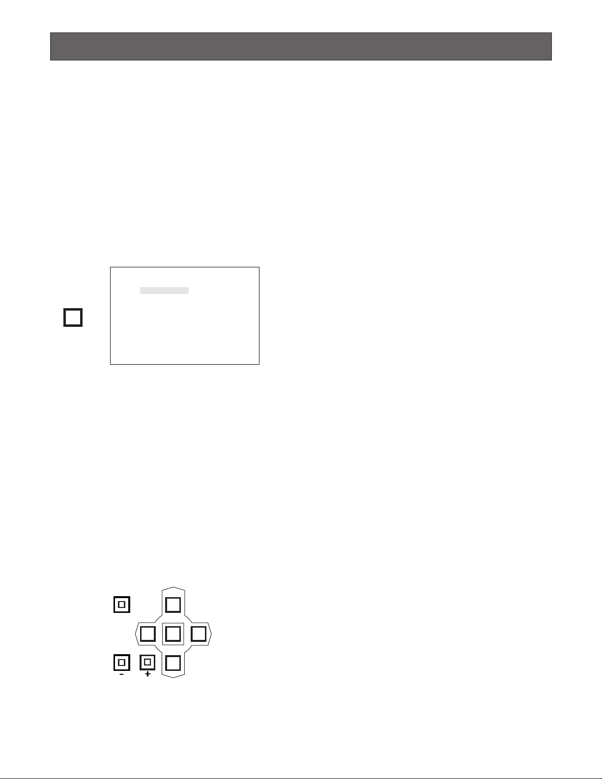
The following buttons are valid in the SETUP MENU:
UP (D): Moves the cursor upward.
DOWN (C): Moves the cursor downward.
LEFT (A): Moves the cursor to the left, or selects
the mode or parameter forwardly.
RIGHT (B): Moves the cursor to the right, or
selects the mode or parameter reversely.
HOME/SET: Executes the selections and displays a
submenu for an item with the (❋) mark.
STILL (-): Selects the mode or parameter.
EL-ZOOM (+): Selects the mode or parameter.
FUNCTION: Selects the next page.
This manual uses the above ( ) symbols hereafter for
following description.
3. Press the [SET UP/ESC] button to execute the currently
highlighted setting and return to the previous menu in
the SETUP MENU.
4. To finalize the setting and return to normal viewing,
press the [SET UP/ESC] button for 2 seconds or more
while the SETUP MENU is displayed.
Note: If alarm is activated during the setup operation,
the SETUP MENU disappears and the display
returns to the normal images. Any settings previously made take effect, even if the [SET UP/ESC] button was not pressed.
WJ-FS616C SETUP MENU
ALARM SETUP *
MULTI OUTPUT SETUP *
SET UP/ESC
SPOT OUTPUT SETUP *
REC/MULTI2 REC OUTPUT *
SYSTEM SETUP *
CAM DOWNLOAD NO
CAM UPLOAD NO
ALL RESET SELECT *
FUNCTION
STILL
EL-ZOOM
LEFT
UP
HOME/SET
DOWN
RIGHT

25
■ Programming Setup Menu
As shown below, the SETUP MENU has nine main submenus: Alarm Setup, Multiscreen Output Setup, Spot Output Setup,
Record Output Setup, Multiscreen 2 Output Setup, System Setup, Camera Download, Camera Upload and All Reset.
Six of these submenus; Alarm Setup, Multiscreen Output Setup, Spot Output Setup, Record Output Setup, Multiscreen 2
Output Setup and System Setup are further divided into additional submenus.
The (❋) mark indicates that the item has a submenu for more detailed setups.
SETUP MENU
ALARM SETUP Alarm Recall
Alarm Schedule
Camera Site Alarm
Camera Switching Signal Loss Alarm
Video Loss Alarm
Alarm Display on the Monitors
Alarm Output Duration
Alarm Buzzer Duration
Alarm Mode on Multiscreen Monitor
Camera Upload
All Reset
Page 26
Alarm Mode on Spot Monitor
Dynamic Recording
Alarm Recording Mode
Camera Title Display
Clock Display
Still Display
Border Display
Camera Display Position
Secret View
Sequence Mode
Camera Title Display
Clock Display
Camera Title Display
Clock Display
Dynamic Recording
Recording Mode
Camera Display Position
Sequence Mode
Clock Setup
Clock Display Position
Camera Title Setup
Camera Title Display Position
Sequence Setup
Lock Mode
Cable Compensation/VD2/Data
Alarm Terminal Setup
Playback Mode
Data Mode
RS-232C Mode
Communication Port Setup
VCR Input Select
Daisy Mode
Unit Address
Password
Camera Download
MULTISCREEN OUTPUT
SETUP
SPOT OUTPUT SETUP
RECORD OUTPUT SETUP
MULTISCREEN 2
OUTPUT SETUP
SYSTEM SETUP
Page 29
Page 31
Page 32
Page 34
Page 36
Page 45
Page 45
Page 46
Sequence Timing (Multiscreen)
Sequence Timing (Spot)