

Panasonic WJ-FS616 Service Manual
SPECIFICATIONS
Power Source : 220 - 240 V AC 50 Hz
Power Consumption : 50 W
Camera Input (1-16) : 1.0 V[p-p] /75 Ω composite video signal
0.5 V[p-p] /75 Ω data signal and 2.5 V[p-p] /75 Ω vertical timing
pulse multiplexed.
Camera Output (1-16) : 1.0 V[p-p] /75 Ω composite video signal
Spot Output: 1.0 V[p-p] /75 Ω composite video signal
Multiscreen Output : 1.0 V[p-p] /75 Ω composite video signal
Y Signal; 0.7 V[p-p], C Signal; 0.3 V[p-p] /75Ω S-video signal
Recording Output : 1.0 V[p-p] /75 Ω composite video signal
Y Signal; 0.7 V[p-p], C Signal; 0.3 V[p-p] /75Ω S-video signal
Playback Input : 1.0 V[p-p] /75 Ω composite video signal
Y Signal; 0.7 V[p-p], C Signal; 0.3 V[p-p] /75Ω S-video signal
Alarm/Remote Control : 37-pin D-sub Connector
VTR Control (RS-232C) : 25-pin D-sub Connector
Ambient Operating Temperature : −10 °C - +50 °C (14 °F - 122 °F)
Ambient Operating Humidity : Less than 90 %
Dimensions : 420 (W) X 88 (H) X 350 (D) mm [16-9/16” (W) X 3-7/16” (H) X 13-3/4” (D)]
Weight : 6.5 kg (14.3 lbs.)
Dimensions and weight are approximate.
Specifications are subject to change without notice.
Video Multiplexer
WJ-FS616
ORDER NO. AVS9801086C8
C 1998 Matsushita Communication Industrial Co., Ltd.
All rights reserved. Unauthorized copying and
distribution is a violation of law.
This service information is designed for experienced repair technicians only and is not designed for use by the
general public.
It does not contain warnings or cautions to advise non-technical individuals of potential dangers in attempting to
service a product.
Products powered by electricity should be serviced or repaired only by experienced professional technicians. Any
attempt to service or repair the product or products dealt with in this service information by anyone else could
result in serious injury or death.
!
WARNING
CAUTION
RISK OF ELECTRIC SHOCK
DO NOT OPEN
CAUTION:
TO REDUCE THE RISK OF ELECTRIC SHOCK,
DO NOT REMOVE COVER (OR BACK). NO USER
SERVICEABLE PARTS INSIDE.
REFER SERVICING TO QUALIFIED SERVICE
PERSONNEL.
This symbol warns the user that uninsulated voltage within
the unit may have sufficient magnitude to cause electric
shock. Therefore, it is dangerous to make any kind of contact
with any inside part of this unit.
This symbol alerts the user that important literature concerning
the operation and maintenance of this has been included.
Therefore, it should be read carefully in order to avoid
any problems.
There are special components used in this equipment which are important for safety. These parts are indicated
by the ” Y ” mark on the schematic diagram and the replacement parts list. It is essential that these critical
parts should be repleced with manufacturer's specified parts to prevent shock, fire, or other hazards.
Do not modify the original design without permission of manufacture.
IMPORTANT SAFETY NOTICE
STANDARD ACCESSORIES
Rack Mounting Bracket ..................................................... 2 pcs.
Screws (M4 x 10) ............................................................. 4 pcs.
Switch Protector ............................................................... 1 pc.

CONTENTS
Major Operating Controls and Their Functions...................................................................................................... 1
Circuit Description
IC Description ........................................................................................................................................................... 12
Adjustment Procedure .............................................................................................................................................. 20
Location of Test Points and Adjusting Controls .................................................................................................... 28
Appearance of ICs, Transistors and Diodes ........................................................................................................... 29
Chip Components...................................................................................................................................................... 30
Wiring Diagram .......................................................................................................................................................... 31
Block Diagram
Main Board ............................................................................................................................................................... 32
Switch Board (1/3) .................................................................................................................................................... 33
Switch Board (2/3) .................................................................................................................................................... 34
Switch Board (3/3) .................................................................................................................................................... 35
Schematic Diagram
Main Board (1/2)/Modular Board/Output Board/Communication Board ................................................................... 38
Main Board (2/2)/Alarm Board/Data Multiplex Board................................................................................................ 39
Switch Board (1/5) .................................................................................................................................................... 42
Switch Board (2/5) .................................................................................................................................................... 43
Switch Board (3/5) .................................................................................................................................................... 46
Switch Board (4/5) / Switch Sub Board..................................................................................................................... 47
Switch Board (5/5) .................................................................................................................................................... 50
Front Board............................................................................................................................................................... 51
Pocket Board ............................................................................................................................................................ 51
Power Board............................................................................................................................................................. 53
Conductor View
Modular Board/Output Board/Communication Board/Alarm Board/Data Multiplex Board........................................36
Main Board ............................................................................................................................................................... 37
Front Board............................................................................................................................................................... 51
Pocket Board ............................................................................................................................................................ 51
Switch Board / Switch Sub Board............................................................................................................................. 52
Power Board............................................................................................................................................................. 53
Exploded View
WJ-FS616................................................................................................................................................................. 54
WV-PB6164E............................................................................................................................................................ 55
Replacement Parts List............................................................................................................................................. 56
1
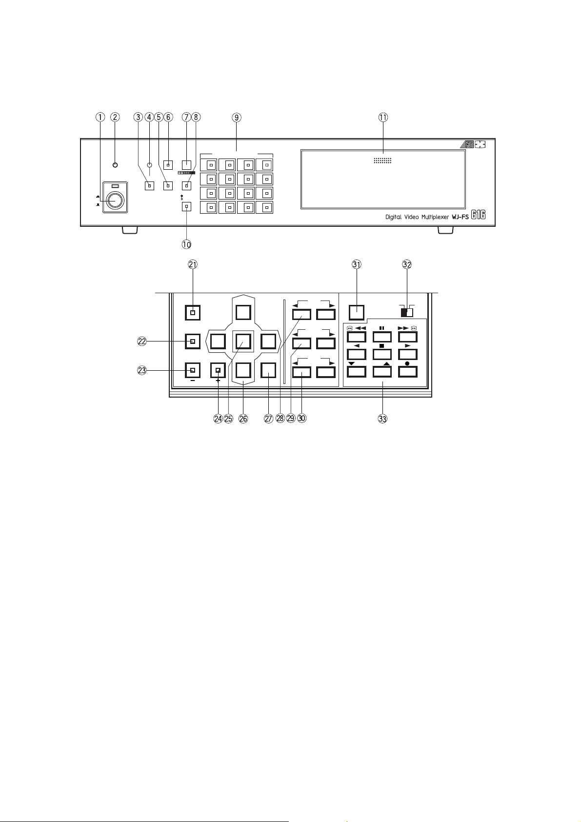
MAJOR OPERATING CONTROLS AND THEIR FUNCTIONS
4
8
12
16
3
7
11
15
2
6
10
14
1
5
9
13
PUSH OPEN
16
POWER
LOCK
ON
OFF
ALARM
MULTI
SCREEN
MULTISCREEN
SELECT
RESET SPOT SEQUENCE
VTR
CAM
CAMERA/PRESET POSITION
FUNCTION
PRE-POSI
LEFT
RIGHT
AUTO
UP
DOWN
HOME/SET
EL-ZOOM
STILL
CURSOR / CAMERA CONTOROL
CLOSE
OPEN
IRIS
NEAR FAR
FOCUS
TELE
WIDE
ZOOM
LOCK
OFF ON
SET UP/ESC
VTR CONTROL
T/L MODE
/ /
<Front View>
1. Power Switch (POWER ON / OFF)
This switch turns the power of the video multiplexer on
or off. The LED (Red) lights up when the power is
turned on.
Caution: The LED indicator blinks to indicate an abnor-
mality of the cooling fan in this appliance.
Turn the power off and refer servicing to qualified
service personnel.
Note: To prevent that the power of the video multiplexer
is turned off accidentally, install the supplied switch
protector.
2. Lock Indicator (LOCK)
This LED (Yellow) indicator lights up to indicate that the
LOCK switch is in ON position.
While this LED is lit, control from the video multiplexer is
disabled.
3. Alarm Reset Button (ALARM RESET)
This button is used to cancel an active alarm. Press this
button, while the alarm function is activated, to reset the
alarm and return the system to the condition before the
alarm function was activated.
The LED (Orange) in the button lights up to indicate that
the alarm suspension mode is selected.
4. Alarm Indicator (ALARM)
This LED (Red) indicator blinks to indicate an alarm
condition exists.
It changes to steady light when the alarm is reset automatically.
To turn the indicator off, press the ALARM RESET button.
5. Spot Monitor Button (SPOT)
This button is used to operate the spot monitor connected to the SPOT OUT connector.
The LED (Green) in the button lights up to indicate that
the spot monitor is selected.
6. Multiscreen Monitor Button (MULTISCREEN)
This button is used to operate the multiscreen monitor
connected to the MULTISCREEN connector.
The LED (Green) in the button lights up to indicate that
the multiscreen monitor is selected.
Note: When REC OUT is used as Multiscreen 2 Output,
this button alternately selects multiscreen output or
multiscreen 2 output.
The LED blinks to indicate that the multiscreen 2
output is selected.

2
The LED (Green) in the button lights up to indicate that
the still mode is selected.
During the setup, this button is used to select the
desired parameter in the setup menu.
24. Electronic Zoom Button (EL-ZOOM)
Decrement Button (–)
This button is used to zoom the picture presently displayed on the multiscreen monitor.
The LED (Green) in the button lights up to indicate that
the zoom mode is selected.
During the setup, this button is used to select the
desired parameter in the setup menu.
25. Home / Set Button (HOME / SET)
This button is used to return to the home position of the
camera.
During the setup, this button is used to display a submenu in the setup menu if the item has its own setting
menu.
26. Direction Arrow Buttons
These buttons are used to operate the Pan/Tilt Head
manually, or to move the cursor to the desired position
in the setup menu of the Video Multiplexer.
UP: Upward
DOWN: Downward
LEFT: Left
RIGHT: Right
27. Auto Button (AUTO)
This button is used to activate the auto panning function
when the specified camera is connected.
28. Iris Control Buttons (IRIS, CLOSE / OPEN)
These buttons are used to close or open the lens iris of
the specified lens mounted on the camera.
When these buttons are pressed at the same time, the
lens iris is reset to the factory settings.
29. Focus Control Buttons (FOCUS, NEAR / FAR)
These buttons are used to adjust the lens focus of the
specified lens mounted on the camera.
When these buttons are pressed at the same time, the
lens focus is automatically set.
30. Zoom Control Buttons (ZOOM, TELE / WIDE)
These buttons are used to adjust the lens zoom of the
specified lens mounted on the camera.
31. Setup/Escape Button (SETUP / ESC)
This button is used to display the setup menu of the
Video Multiplexer.
During the setup, press this button to execute the currently selected setting and return to the previous setup
menu.
32. Lock Switch (LOCK OFF / ON)
This switch can be used to lock out operation of the
video multiplexer panel controls.
While this switch is in ON position, control from the
video multiplexer is disabled.
7. Multiscreen Selection Button (MULTISCREEN
SELECT)
This button is used to select the multiscreen pattern to
be displayed on the multiscreen monitor while monitoring the camera picture or VTR playback picture.
Pressing this button repeatedly will switch the screen as
follows:
Camera Picture:
4→7→9→10→13→16→4 screen segments
VTR Playback Picture:
4→9→16→4 screen segments
8. Sequence Button (SEQUENCE)
This button is used to activate the sequence mode. In
this mode, a series of camera pictures is displayed in
succession on the monitor screen for the specified duration.
The LED (Green) in the button lights up to indicate that
this mode is selected.
9. Camera Number Buttons (CAMERA)
Preset Position Number Buttons
(PRESET POSITION)
CAMERA:
These buttons are used to select the desired camera picture.
The LED (Green) in the button lights up to indicate
the camera number presently selected.
PRESET POSITION:
These buttons are used in combination with the
PRE POSI button to assign a preset position number to the selected camera.
10. VTR / Camera Selection Button (VTR / CAM)
This button is used to select the camera picture or VTR
playback picture to be displayed on the multiscreen
monitor screen.
The LED (Green) in the button lights up to indicate that
the VTR mode is selected.
Note: The above operation is not valid unless multi-
screen output is selected by pressing the
Multiscreen Monitor button.
11. Control Panel
Press “PUSH OPEN” to open the control panel.
21. Function Button (FUNCTION)
This button is used to display the VTR playback picture
with the camera pictures on the multiscreen monitor.
During the setup, this button is used to select the next
page.
22. Preset Position Button (PRE-POSI)
This button is used to assign a preset position to a
specified camera.
23. Still Button (STILL)
Increment Button (+)
This button is used to still the picture displayed on the
multiscreen monitor.

3
33. VTR Control Buttons
These buttons are used for remote control of the VTR that is connected to the Video Multiplexer.
The buttons function as shown below.
: Rewind : Pause
: Fast Forward : Reverse Play
: Stop : Play
: Decreases recording duration : Increases recording duration
: Record
/
/
<Rear View>
16 15 14 13 12 11 10 9 8 7 6 5 4 3 2 1
16 15 14 13 12 11 10 9 8 7 6 5 4 3 2 1
A BTA B
R
G
N
D
G
N
D
RS485 TERM.
LINE
SELECT
CAMERA
SW IN
GENLOCK
IN
OFF ON 2 4
SPOT
REC OUT PLAY IN
MUL TISCREEN
VTR CONTROL
OUT I N
VIDEO VIDEOVIDEO
REMOTE
ALARM/REMOTE
OUT
TERM.
OFF
INOUT
ON
SIGNAL
GND
DATA
CAMERA
IN
CAMERA
OUT
S
–
VIDEO S
–
VIDEO S
–
VIDEO
RS
–
232C
41. Camera Output Connectors (CAMERA OUT)
The video signal connected to the Camera Input
Connector (CAMERA IN) is looped through to these
connectors with an automatic 75Ω termination.
The camera control signal multiplexed on the video signal is not available at this connector. When the Power
Switch of the Video Multiplexer is turned off, no signal is
present at this connector.
42. Camera Input Connectors (CAMERA IN)
These connectors accepts either a colour or B/W composite video signal from the camera. In addition, the
VD2 signal for synchronizing the vertical timing of the
cameras, and data to control camera site devices are
multiplexed through this connector.
43. RS485 Terminal (RS485)
This terminal is used to exchange control data with the
camera site.
44. Termination Switch (TERM., OFF / ON)
This switch is used to enable termination of the RS485
terminal.
45. Line Selection Switch (LINE SELECT, 2/4)
This switch lets you select either Full Duplex (4 lines) or
Half Duplex (2 lines) for the communication lines.
46. Camera Switching Input Connector
(CAMERA SW IN)
The camera switching pulse from the time lapse VTR is
supplied to this connector.
The camera switching interval (Sequential Dwell Time)
can be synchronized with the time lapse mode set in the
associated time lapse VTR.
47. Gen-Lock Input Connector (GENLOCK IN)
The Gen-Lock signal can be supplied to this connector
for synchronizing the system.
48. Spot Connector (SPOT OUT / IN)
IN: This connector accepts the video output signal from
the external system.
The supplied video can be displayed on the spot
monitor screen with the specified conditions.
OUT: This connector supplies the video output signal for
the spot monitor.
49. Record Output Connector (REC OUT, VIDEO /
S-VIDEO)
The recording signal for the time lapse VTR is provided
via this connector.
This connector can also be used as multiscreen output
2 with the specified conditions.
50. Playback Input Connector (PLAY IN, VIDEO /
S-VIDEO)
The playback signal from the time lapse VTR is supplied
to this connector.
51. Multiscreen Output Connector
(MULTISCREEN)
The video output signal for the multiscreen monitor is
provided via this connector.
52. RS-232C Port (VTR CONTROL, RS-232C)
The VTR control signal for the time lapse VTR is provided via this connector.
Connecting a PC to this connector will allow you to
remote control the video multiplexer.

4
53. Remote Output Connector (VTR CONTROL,
REMOTE OUT)
The VTR control signal for the time lapse VTR is provided via this connector.
You can select on the setup menu whether to have the
VTR control signal supplied from this connector or the
RS-232C Port.
54. Alarm / Remote Control Connector (ALARM /
REMOTE)
This connector accepts the alarm signals from the associated alarm sensor units and the control signals from
the external system.
55. Power Cord
56. Signal Ground Terminal (SIGNAL GND)
57. Termination Switch (TERM., OFF / ON)
This switch is used to enable termination of the video
multiplexer’s data port.
58. Data Ports (DATA, OUT / IN)
These ports are used to exchange control data with the
WV-CU550A System Controller or a PC in a system.
INSTALLATIONS
The installations described below should be made by qualified service personnel or system installers.
■ Installing the WV-PB6164E Data Multiplex Boards
When controlling the camera with the multiplexed control data by connecting a coaxial cable, the WVPB6164E Data Multiplex Board must be installed in the
Video Multiplexer.
Four data multiplex boards are included with the WJFS616 for cameras 1 to 4.
Please note that additional multiplex boards are available for purchase as model WV-PB6164E Data
Multiplex Boards, which includes four control boards.
Caution: Before installing boards, be sure to turn off the
Power Switch of the video multiplexer.
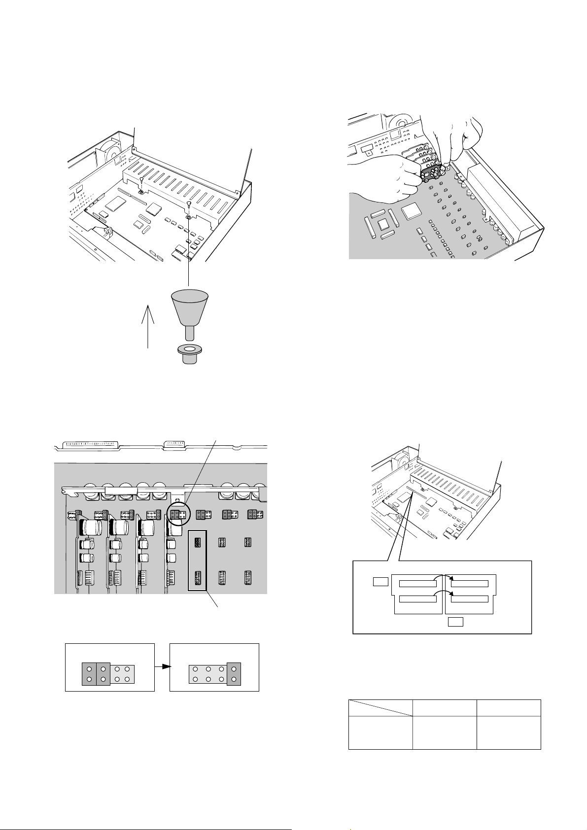
1. Remove the six screws on the top cover of the video
multiplexer as shown below.
2. Remove the top cover.
3. Remove the four screws on the board as shown below.
Front
Rear
4. Remove the one screw shown below. Then turn over
the printed circuit board with the front side up.
5
5. Pull out the two knobs from the bracket shown below.
Then remove the bracket.
6. Set the jumper connector, located at the top left of the
board to be installed, to the position shown below.
7. Insert the board and confirm that the position is correct.
Then push it in straight.
8. After installing the boards, secure them by tightening the
screws and knobs shown above.
Note: Some settings for the VD2 signal and control data
will be necessary from the setup menu of the Video
Multiplexer.
Jumper Connector
Board Connector
Initial State Installed State
2
1
8
7
2
1
8
7
■ T ally Output Setting
Allows you to use the Alarm Input Terminal as Tally
Output Terminal by changing two internal connections.
1. Disassemble the video multiplexer as described for
installing the Data Multiplex Boards on page 4.
2. Move the two connectors from the ALM side to the TLY
side as shown above.
The relation between the connector numbers and channel numbers is shown in the table below.
10 1
CN33
91
CN32
ALM
TLY
10 1
CN37
91
CN36
Alarm Input
CN33
CN32
Tally Output
CN37
CN36
CH9 - CH16
CH1 - CH8

6
■ Dip Switch Setting
● Alarm Output Setting
1. Disassemble the video multiplexer as described for
installing the Data Multiplex Boards on page 4.
2. Set switches (SW3/SW4/SW5) on the board to choose
the alarm control signals as either Open Collector (O.C)
or Pulse (VTR).
Open Collector (O.C): 16V DC 100 mA max.
Pulse (VTR): +5V DC approx. 500 ms
The above switch positions are the initial factory settings.
VTR O.C
SW5
SW3
VTR O.C
SW4
VTR O.C
SW3 : Alarm Output
SW4 : Alarm Reset Output
SW5 : Alarm & SW Output
● Dummy Black Burst Setting
According to the initial factory setting, the Dummy Black
Burst signal is supplied to the REC OUT connector as
needed to overwrite any picture displayed by error. If
this function is not required, set the switch SW1 to the
position shown below.
1. Disassemble the video multiplexer as described for
installing the Data Multiplex Boards on page 4.
2. Set switch (SW1) on the board to the position shown
above.
SW1
OFF
SW1 : Record Output
■ WJ-FS616 Video Multiplexer
● Mounting in the Rack
1. Remove the four rubber feet by removing the four
screws on the bottom of the video multiplexer.
2. Place the rack mounting brackets on both sides of the
video multiplexer and tighten with the four supplied
screws (M4 X10).
3. Install the video multiplexer with the rack mounting
brackets in the rack by using four screws (not included).
Cautions
• Do not block the ventilation opening or slots on the
cover to prevent the appliance from overheating.
Always keep the temperature in the rack within 50
°C (122 °F).
• Secure the rear of the appliance to the rack by
using additional mounting brackets (procured locally) if the rack is subject to vibrations.
Remove 4 rubber feet
7
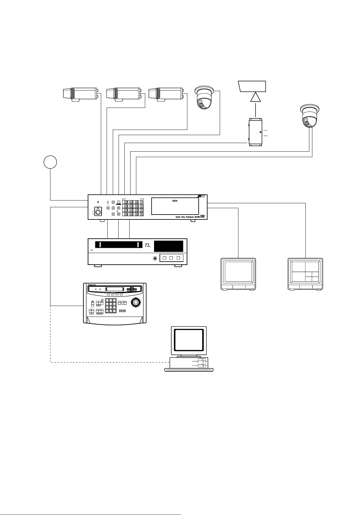
Basic System Connection
SYSTEM CONNECTIONS
Shown below is an example of a basic system connection.
4
8
12
16
3
7
11
15
2
6
10
14
1
5
9
13
PUSH OPEN
16
POWER
LOCK
ON
OFF
ALARM
MULTI
SCREEN
MULTISCREEN
SELECT
RESET SPOT SEQUENCE
VCR
CAM
CAMERA/PRESET POSITION
Video
Data RS-485
Video Multiplexer
WJ-FS616
Time Lapse VTR
Personal Computer
(Software)
System Controller
WV-CU550A
Spot Monitor
Live 1-16ch
Multiscreen Monitor
Live 1-16ch
Playback 1-16ch
RS-232C/Wired
Alarm Sensor
AUX
Alarm
1 2 3
4 5 6
7 8 9
MON CA M
0
System Controller for WJ-FS616
F3 F4F2F1
8
CAMERA
IN
CAMERA
OUT
16 15 14 13 5 4 3 2 1
16 15 14 13 5 4 3 2 1
A BTA B
R
G
N
D
G
N
D
RS485
AUX
Alarm
Video Multiplexer WJ-FS616
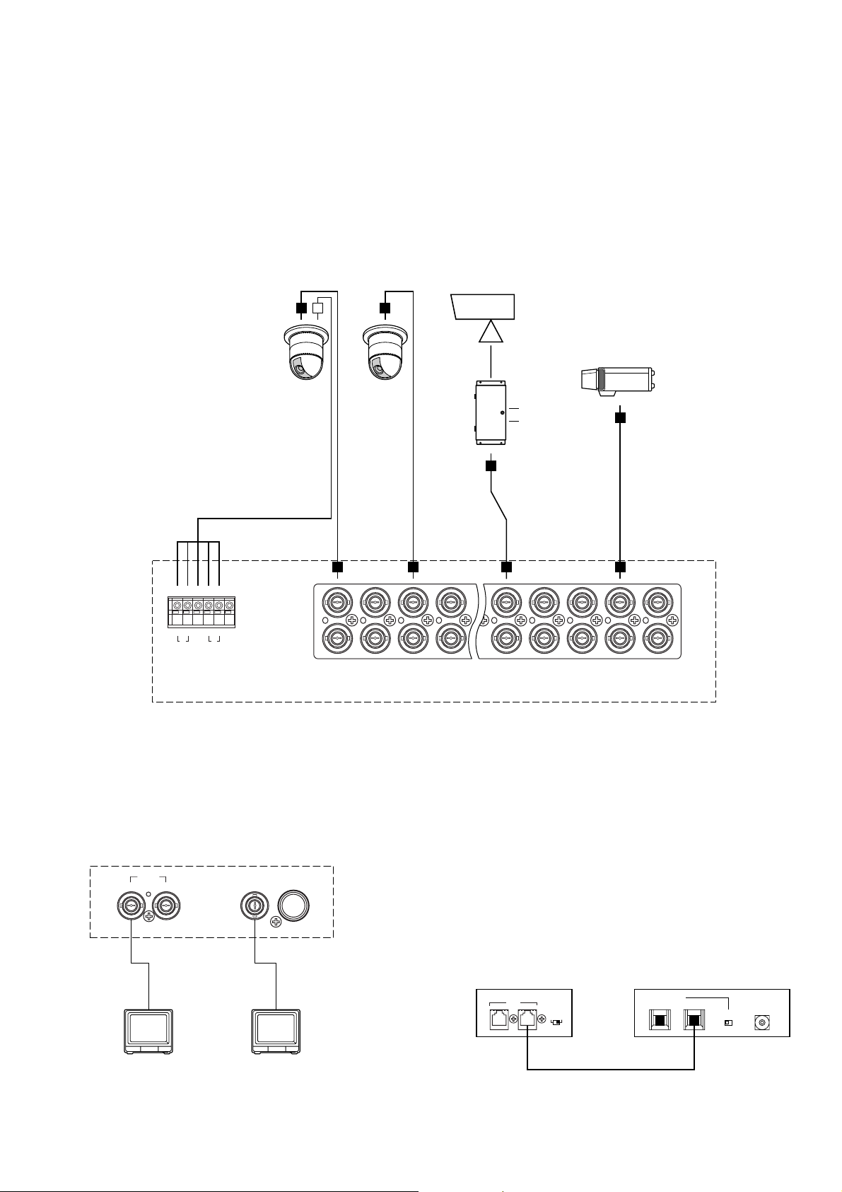
■ Connection with the Camera Sites
Connect the Camera Site equipment to the Camera
Input Connectors (CAMERA IN 1-16) on the rear of the
Video Multiplexer.
Note: Make sure that the cable length between the
camera site and the WJ-FS616 Video Multiplexer is
less than 1 200 m (4 000 ft) when using RG-6/U (5C
- 2V) or equivalent cables.
Connect the Camera Site equipment to the RS485
Terminal on the rear of the Video Multiplexer, when
specified equipment is connected.
Note: If you use cables assembled from locally pro-
cured materials, it is important that only high quality,
data grade cable, suitable for RS-485 “2-wire twisted pair shielded cable” is used.
Low grade cable will result in unstable operation of
the system.
■ Connection with the Monitors
Connect the Monitors to the Spot Output (SPOT OUT)
Connector and Multiscreen (MULTISCREEN) Connector
on the rear of the Video Multiplexer.
SPOT
MULTISCREEN
OUT I N
VIDEO
S
–
VIDEO
Video Multiplexer
WJ-FS616
■ Connection with the WV-CU550A
System Controller
If the supplied 6-conductor cable assembly is used, simply plug one end of the cable into the DATA IN port of
the Video Multiplexer and the other end into DATA OUT
port on the System Controller.
If you use cables assembled from locally procured
materials, it is important that only high quality, data
grade cable, suitable for RS-485 “2-wire twisted pair
shielded cable” is used.
Low grade cable will result in unstable operation of the
system.
TERM.
OFF
INOUT
ON
DATA
IN OUT
TERM
ON OFF
DATA
0
1
2
3
4
5
6
7
8
9
CONTROLLER
UNIT NO.
1-8
Video Multiplexer
WJ-FS616
System Controller
WV-CU550A
9
● Setting the Termination and Controller
Unit Number
The Termination Switch and the Controller Unit Number
Switch are located on the rear of the System Controller.
When combined with the WJ-FS616 Video Multiplexer,
always keep these switches in the positions shown
below.
TERM. MODE
ON OFF
0
OFF
ON
● Setting the Mode Selection Switch
The Mode Selection Switch, that selects the operation
mode of the System Controller, is located on the rear of
the System Controller.
When combined with the WJ-FS616 Video Multiplexer,
always keep these switches in the positions shown
below.
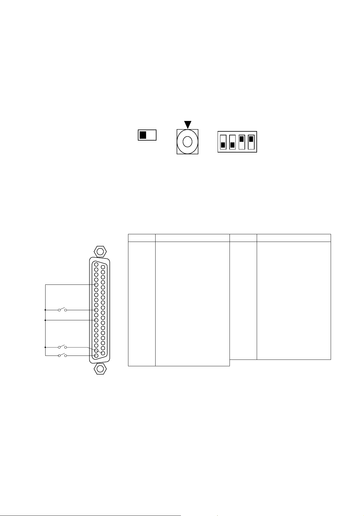
■ Connection with Alarm Sensors
Connect the sensor switches to the Alarm/Remote (ALARM/REMOTE) Control Connector on the rear of the Video Multiplexer
as shown in the example below.
37
19
20
1
SW2
SW1
SW16
GND
ALARM/REMOTE
1
2
3
4
5
6
7
8
9
10
11
12
13
14
15
16
17
18
19
Function
Electronic Zoom
Sequence
Spot
Alarm/Remote Select Input
Sequence SW for Spot Output
Not Used
Alarm Recover Input
Alarm Output
Alarm 16
Alarm 14
Ground
Alarm 11
Alarm 9
Alarm 8
Alarm 6
Ground
Alarm 3
Alarm 1
Pin No. Designation
20
21
22
23
24
25
26
27
28
29
30
31
32
33
34
35
36
37
Still Picture
VTR/Camera Select
Multiscreen Select
Multiscreen
Ground
Alarm & SW Output
Time Adjust Input
Alarm Reset Output
Ground
Alarm 15
Alarm 13
Alarm 12
Alarm 10
Ground
Alarm 7
Alarm 5
Alarm 4
Alarm 2
Pin No. Designation

10
■ Connection with the Time Lapse VTR
Connect the Time Lapse VTR as shown in the example below.
19
20
1
ALARM/REMOTE
37
CAMERA
SW IN
REC OUT PLAY IN
VIDEO VIDEO
VIDEO IN
CAMERA
SW OUT
GND
S-VIDEO
AUDIO
VIDEO OUT
1 2 3 4 5 6 7 8 9 10 11 12 13 14 15 16
89
28 26
13 4 7 16
1
2
3
4
ALARM
IN
COM
ALARM
RESET IN
ALARM
RECOVER OUT
5
6
7
8
ALARM
OUT
1 SHOT IN
TAPE END
OUT
9
10
11
12
WARNING
OUT
HUMID OUT
REC REVIEW
OUT
13
14
15
16
SERIES
REC IN
TIME
ADJUST IN
TIME
ADJUST OUT
COM REC OUT
SERIES
REC OUT
Video Multiplexer
WJ-FS616
Time Lapse VTR
S – VIDEO S – VIDEO
 Loading...