

Panasonic WJ-FS616 User Manual
Video Multiplexer
WJ-FS616
Before attempting to connect or operate this product, please read these instructions completely
Warning:
This equipment generates and uses radio frequency energy and if not installed and used properly, i.e., in strict
accordance with the instruction manual, may cause harmful
interference to radio communications. It has been tested
and found to comply with the limits for a Class A computing
device pursuant to Subpart J of Part 15 of FCC Rules,
which are designed to provide reasonable protection
against such interference when operated in a commercial
environment.
WARNING:
TO PREVENT FIRE OR ELECTRIC SHOCK HAZARD, DO NOT EXPOSE THIS APPLIANCE TO RAIN OR MOIS
TURE.
The lightning flash with arrowhead symbol, within an equilateral triangle, is
intended to alert the user to the presence of uninsulated "dangerous voltage"
within the product's enclosure that may
be of sufficient magnitude to constitute a
risk of electric shock to persons.
The exclamation point within an equilateral triangle is intended to alert the user
to the presence of important operating
and maintenance (servicing) instructions
in the literature accompanying the appliance.
The serial number of this product may be found on the bottom of the unit.
You should note the serial number of this unit in the space
provided and retain this book as a permanent record of your
purchase to aid identification in the event of theft.
Model No. WJ-FS616
Serial No.
CAUTION:
TO REDUCE THE RISK OF ELECTRIC SHOCK, DO
NOT REMOVE COVER (OR BACK). NO USER SERVICEABLE PARTS INSIDE.
REFER SERVICING TO QUALIFIED SERVICE PERSONNEL.
CAUTION
RISK OF ELECTRIC SHOCK
DO NOT OPEN
SA 1965
SA 1966
CONTENTS
PREFACE ................................................................................................................................................................................ 1
FEATURES .............................................................................................................................................................................. 1
PRECAUTIONS ....................................................................................................................................................................... 2
MAJOR OPERATING CONTROLS AND THEIR FUNCTIONS ................................................................................................. 3
INSTALLATIONS ..................................................................................................................................................................... 10
SYSTEM CONNECTIONS ....................................................................................................................................................... 14
SETUP MENU ......................................................................................................................................................................... 21
Setup Menu ......................................................................................................................................................................... 22
Alarm Setup Menu ............................................................................................................................................................... 23
Multiscreen Output Menu .................................................................................................................................................... 25
Spot Output Setup ............................................................................................................................................................... 27
Record Output Setup ........................................................................................................................................................... 27
Multiscreen 2 Output Setup ................................................................................................................................................. 29
System Setup ....................................................................................................................................................................... 30
Camera Download ............................................................................................................................................................... 36
Camera Upload ................................................................................................................................................................... 37
All Reset................................................................................................................................................................................ 37
OPERATING PROCEDURES .................................................................................................................................................. 38
MONITOR CONTROL FUNCTION........................................................................................................................................ 38
CAMERA CONTROL FUNCTION ........................................................................................................................................ 42
ALARM CONTROL FUNCTION ............................................................................................................................................ 44
OTHER FUNCTIONS ........................................................................................................................................................... 47
SETUP MENU OPERATIONS (with WV-CU550A) ................................................................................................................... 48
OPERATING PROCEDURES (with WV-CU550A) .................................................................................................................... 49
MONITOR CONTROL FUNCTION ....................................................................................................................................... 49
CAMERA CONTROL FUNCTION ........................................................................................................................................ 50
ALARM CONTROL FUNCTION ........................................................................................................................................... 51
SYSTEM EXPANSION ............................................................................................................................................................. 52
APPENDIX .............................................................................................................................................................................. 55
SPECIFICATIONS ................................................................................................................................................................... 59
STANDARD ACCESSORIES ................................................................................................................................................... 59
For U.S.A
Caution:
Before attempting to connect or operate this product,
please read the label on the bottom.
-1-
The WJ-FS616 Video Multiplexer is designed to multiplex the field signals from video cameras and record
the camera images on a time lapse VCR. Up to 16
cameras can be connected to the unit for monitoring
images in multiscreen, sequence, still or electronic
zoom mode on a video monitor screen.
The WJ-FS616 allows you to control camera functions
such as lens focussing, zooming, and iris, positioning
of the pan/tilt head, etc. This makes the system highly
flexible and sophisticated, and allows expansion to up
to 64 cameras.
PREF ACE
FEATURES
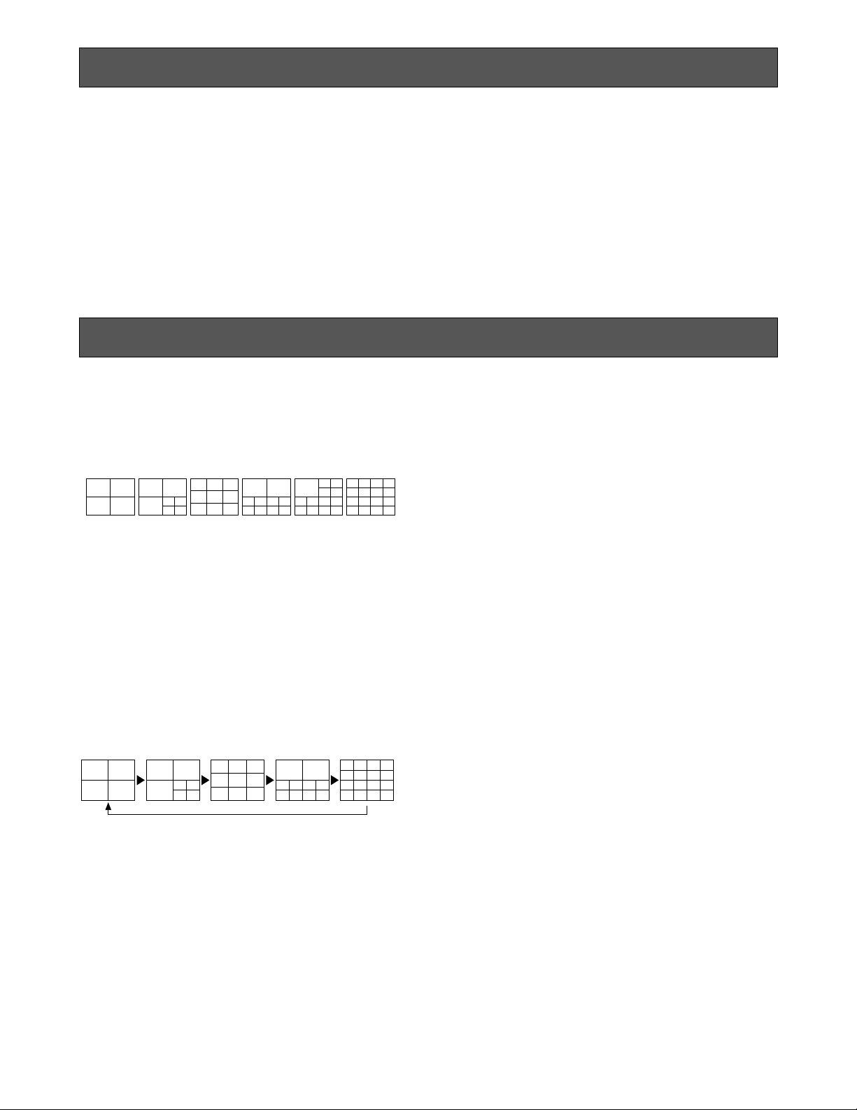
• The pictures of any connected camera can be displayed on full screen or on a 4, 7, 9, 10, 13 and 16
multiscreen as shown below.
(7, 10 and 13 multiscreens are not available for
playback pictures.)
In addition, one playback picture can be displayed
with camera pictures in 4, 7, 10 and 13 multiscreens.
• The pattern of a spot sequence consisting of up to
32 steps can be programmed by presetting the
channel order and individual dwell time.
The pattern of a 4, 7, 9, 10, 13, or 16 multiscreen
sequence consisting of up to 5 steps can be programmed as shown below.
4-SEGMENT
SCREEN
7-SEGMENT
SCREEN
9-SEGMENT
SCREEN
10-SEGMENT
SCREEN
13-SEGMENT
SCREEN
16-SEGMENT
SCREEN
2 sec2 sec 5 sec 3 sec 1 sec
4 sec
• Electronic zoom and still image functions are available. The zoom area can be selected with the
direction arrow buttons.
• Up to 16 camera images multiplexed by the field
rate are available at the REC OUT connector for
recording on the time lapse VCR. Alarm priority
recording is supported.
• Camera functions such as pan/tilt, lens zoom, focus
and iris, and camera setup can be controlled via a
single cable or RS-485 interface.
• The WJ-FS616 has a versatile alarm mode to optimize its multiscreen output, spot output, and record
output.
• REC, PLAY, REW, FF, etc. can be controlled from
the front panel of the video multiplexer, via the RS232C interface or the wired remote control terminal
of the Panasonic Time Lapse VCR.
• The WJ-FS616 can be controlled from a PC or the
WV-CU550A System Controller via RS-232C or RS485 interface.

-2-
• Refer all work related to the installation of this
product to qualified service personnel or system
installers.
• Do not block the ventilation opening or slots on
the cover.
To prevent the appliance temperature from rising,
place the appliance at least 5 cm (2 inches) away
from the wall.
• Do not drop metallic parts through slots.
This could permanently damage the appliance. Turn
the power off immediately and refer servicing to
qualified service personnel.
• Do not attempt to disassemble the appliance.
To prevent electric shock, do not remove screws or
covers.
There are no user-serviceable parts inside. Refer
maintenance to qualified service personnel.
• Handle the appliance with care.
Do not strike or shake, as this may damage the
appliance.
• Fully charge up the backup battery.
Keep the appliance turned on for at least 48 hours
to recharge the backup battery. This procedure is
necessary when using the appliance for the first
time or after it has been unplugged for a long time
from the AC outlet. Insufficient charging of the battery may cause erasure of settings if the AC power
supply should fail. The battery, if fully charged, will
back up the settings for 72 hours in an ordinary
environment.
• We recommend that you note down your settings
and retain them. Power or battery failure may
erase settings you entered.
• Do not expose the appliance to water or
moisture, nor try to operate it in wet areas.
Do take immediate action if the appliance becomes
wet. Turn the power off and refer servicing to qualified service personnel. Moisture can damage the
appliance and also cause electric shock.
• Do not use strong or abrasive detergents when
cleaning the appliance body.
Use a dry cloth to clean the appliance when it is
dirty.
When the dirt is hard to remove, use a mild detergent and wipe gently.
• Do not operate the appliance beyond its
specified temperature, humidity or power source
ratings.
Do not use the appliance in an extreme environment
where high temperature or high humidity exists.
Use the appliance at temperatures within −10°C +50°C (14°F - 122°F) and a humidity below 90 %.
The input power source for this appliance is 120 V
AC 60 Hz.
PRECAUTIONS
-3-
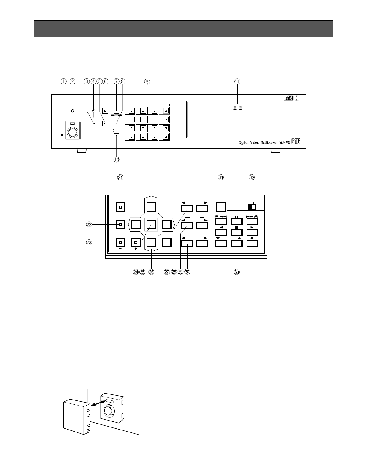
MAJOR OPERATING CONTROLS AND THEIR FUNCTIONS
4
8
12
16
3
7
11
15
2
6
10
14
1
5
9
13
PUSH OPEN
16
POWER
LOCK
ON
OFF
ALARM
MULTI
SCREEN
MULTISCREEN
SELECT
RESET SPOT SEQUENCE
VCR
CAM
CAMERA/PRESET POSITION
FUNCTION
PRE-POSI
LEFT
RIGHT
AUTO
UP
DOWN
HOME/SET
EL-ZOOM
STILL
CURSOR / CAMERA CONTOROL
CLOSE
OPEN
IRIS
NEAR FAR
FOCUS
TELE
WIDE
ZOOM
LOCK
OFF ON
SET UP/ESC
VCR CONTROL
T/L MODE
/ /
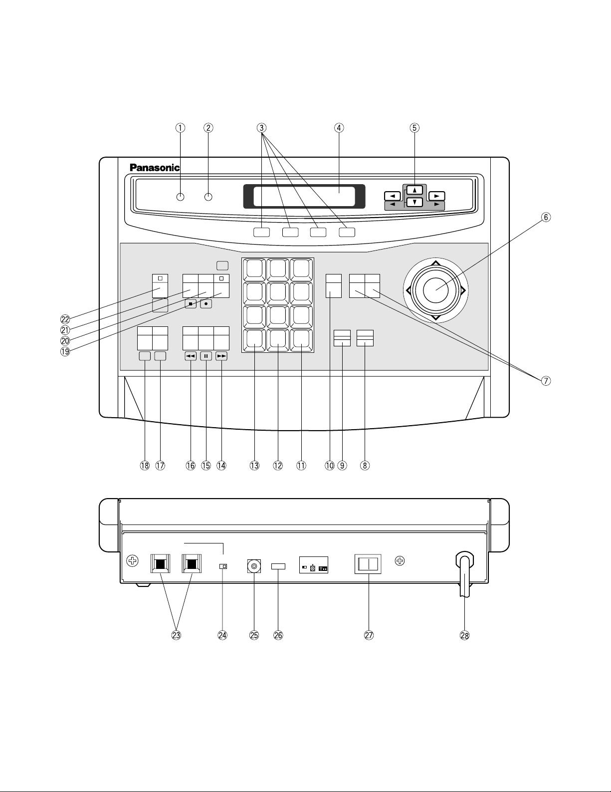
■ Video Multiplexer WJ-FS616
<Front View>
1. Power Switch (POWER ON / OFF)
This switch turns the power of the video multiplexer
on or off. The LED lights up when the power is
turned on.
Caution: The LED indicator blinks to indicate an
abnormality of the cooling fan in this appliance.
Turn the power off and refer servicing to qualified service personnel.
Note: To prevent that the power of the video multi-
plexer is turned off accidentally, install the supplied switch protector as shown below.
2. Lock Indicator (LOCK)
This LED (Yellow) indicator lights up to indicate that
the LOCK switch is in ON position.
While this LED is lit, control from the video multiplexer is disabled.
3. Alarm Reset Button (ALARM RESET)
This button is used to cancel an active alarm. Press
this button, while the alarm function is activated, to
reset the alarm and return the system to the condition before the alarm function was activated.
The LED (Orange) in the button lights up to indicate
that the alarm suspension mode is selected.
4. Alarm Indicator (ALARM)
This LED (Red) indicator blinks to indicate an alarm
condition exists.
It changes to steady light when the alarm is reset
automatically.
To turn the indicator off, press the ALARM RESET
button.
SWITCH
PROTECTOR

21. Function Button (FUNCTION)
This button is used to display the VCR playback
picture with the camera pictures on the multiscreen
monitor.
During the setup, this button is used to select the
next page.
22. Preset Position Button (PRE-POSI)
This button is used to assign a preset position to a
specified camera.
23. Still Button (STILL)
Increment Button (+)
This button is used to still the picture displayed on
the multiscreen monitor.
The LED (Green) in the button lights up to indicate
that the still mode is selected.
During the setup, this button is used to select the
desired parameter in the setup menu.
24. Electronic Zoom Button (EL-ZOOM)
Decrement Button (–)
This button is used to zoom the picture presently
displayed on the multiscreen monitor.
The LED (Green) in the button lights up to indicate
that the zoom mode is selected.
During the setup, this button is used to select the
desired parameter in the setup menu.
25. Home / Set Button (HOME / SET)
This button is used to return to the home position of
the camera.
During the setup, this button is used to display a
submenu in the setup menu if the item has its own
setting menu.
26. Direction Arrow Buttons
These buttons are used to operate the Pan/Tilt
Head manually, to move the cursor position in the
setup menu of the Video Multiplexer, or to select an
area for Electric Zooming.
UP: Upward
DOWN: Downward
LEFT: Left
RIGHT: Right
27. Auto Button (AUTO)
This button is used to activate the auto panning
function when the specified camera is connected.
28. Iris Control Buttons (IRIS, CLOSE / OPEN)
These buttons are used to close or open the lens
iris of the specified lens mounted on the camera.
When these buttons are pressed at the same time,
the lens iris is reset to the factory settings.
29. Focus Control Buttons (FOCUS, NEAR / FAR)
These buttons are used to adjust the lens focus of
the specified lens mounted on the camera.
When these buttons are pressed at the same time,
the lens focus is automatically set.
-4-
5. Spot Monitor Button (SPOT)
This button is used to operate the spot monitor connected to the SPOT OUT connector.
The LED (Green) in the button lights up to indicate
that the spot monitor is selected.
6. Multiscreen Monitor Button (MULTISCREEN)
This button is used to operate the multiscreen monitor connected to the MULTISCREEN connector.
The LED (Green) in the button lights up to indicate
that the multiscreen monitor is selected.
Note: When REC OUT is used as Multiscreen 2
Output, this button alternately selects multiscreen output or multiscreen 2 output.
The LED blinks to indicate that the multiscreen
output 2 is selected.
7. Multiscreen Selection Button (MULTISCREEN
SELECT)
This button is used to select the multiscreen pattern
to be displayed on the multiscreen monitor while
monitoring the camera picture or VCR playback
picture.
Pressing this button repeatedly will switch the
screen as follows:
Camera Picture:
4→7→9→10→13→16→4 screen segments
VCR Playback Picture:
4→9→16→4 screen segments
8. Sequence Button (SEQUENCE)
This button is used to activate the sequence mode.
In this mode, a series of camera pictures is displayed in succession on the monitor screen for the
specified duration.
The LED (Green) in the button lights up to indicate
that this mode is selected.
9. Camera Number Button (CAMERA)
Preset Position Number Buttons
(PRESET POSITION)
CAMERA:
These buttons are used to select the desired
camera picture.
The LED (Green) in the button lights up to indicate the camera number presently selected.
PRESET POSITION:
These buttons are used in combination with the
PRE POSI button to assign a preset position
number to the selected camera.
10. VCR / Camera Selection Button (VCR / CAM)
This button is used to select the camera picture or
VCR playback picture to be displayed on the multiscreen monitor screen.
The LED (Green) in the button lights up to indicate
that the VCR mode is selected.
Note: The above operation is not valid unless multi-
screen output is selected by pressing the
Multiscreen Monitor button.
11. Control Panel
Press “PUSH OPEN” to open the control panel.

-5-
33. VCR Control Buttons
These buttons are used for remote control of the
VCR that is connected to the Video Multiplexer.
The buttons function as shown below.
: Rewind
: Pause
: Fast Forward
: Reverse Play
: Stop
: Play
: Decreases recording duration
: Increases recording duration
: Record
/
/
30. Zoom Control Buttons (ZOOM, TELE / WIDE)
These buttons are used to adjust the lens zoom of
the specified lens mounted on the camera.
31. Setup/Escape Button (SETUP / ESC)
This button is used to display the setup menu of the
Video Multiplexer.
During the setup, press this button to execute the
currently selected setting and return to the previous
setup menu.
32. Lock Switch (LOCK OFF / ON)
This switch can be used to lock out operation of the
video multiplexer panel controls.
While this switch is in ON position, control from the
video multiplexer is disabled.
<Rear View>
16 15 14 13 12 11 10 9 8 7 6 5 4 3 2 1
16 15 14 13 12 11 10 9 8 7 6 5 4 3 2 1
A BTA B
R
G
N
D
G
N
D
RS485 TERM.
LINE
SELECT
CAMERA
SW IN
GENLOCK
IN (VS)
OFF ON 2 4
SPOT
REC OUT PLAY IN
MULTISCREEN OUT
VCR CONTROL
RS–232C
OUT I N
VIDEO S–VIDEO S–VIDEO S–VIDEOVIDEOVIDEO
REMOTE
ALARM/REMOTE
OUT
TERM.
OFF
INOUT
ON
SIGNAL
GND
DATA
CAMERA
IN
CAMERA
OUT
41. Camera Output Connector (CAMERA OUT)
The video signal connected to the Camera Input
Connector (CAMERA IN) is looped through to these
connector with an automatic 75 Ω termination.
The camera control signal multiplexed on the video
signal is not avairable at this connector. When the
Power Switch of the Video Multiplexer is turned off,
no signal is present at this connector.
42. Camera Input Connector (CAMERA IN)
These connectors accepts either a color or B/W
composite video signal from the camera. In addition, the VD2 signal for synchronizing the vertical
timing of the cameras, and data to control camera
site devices are multiplexed through this connector.
43. RS485 Terminal (RS485)
This terminal is used to exchange control data with
the camera site.
44. Termination Switch (TERM., OFF / ON)
This switch is used to enable termination of the
RS485 terminal.
45. Line Selection Switch (LINE SELECT, 2/4)
This switch lets you select either Full Duplex (4
lines) or Half Duplex (2 lines) for the communication
lines.
46. Camera Switching Input Connector
(CAMERA SW IN)
The camera switching pulse from the time lapse
VCR is supplied to this connector.
The camera switching interval (Sequential Dwell
Time) can be synchronized with the time lapse
mode set in the associated time lapse VCR.
47. Gen-Lock Input Connector (GENLOCK IN (VS))
The Gen-Lock signal can be supplied to this connector for synchronizing the system.
48. Spot Connector (SPOT, OUT / IN)
IN: This connector accepts the video output signal
from the external system.
The supplied video can be displayed on the
spot monitor screen with the specified conditions.
OUT: This connector supplies the video output sig-
nal for the spot monitor.

-6-
49. Record Output Connector (REC OUT, VIDEO /
S-VIDEO)
The recording signal for the time lapse VCR is provided via this connector.
This connector can also be used as multiscreen output 2 with the specified conditions.
50. Playback Input Connector (PLAY IN, VIDEO /
S-VIDEO)
The playback signal from the time lapse VCR is supplied to this connector.
51. Multiscreen Output Connector (MULTISCREEN
OUT)
The video output signal for the multiscreen monitor
is provided via this connector
52. RS-232C Port (VCR CONTROL, RS-232C)
The VCR control signal for the time lapse VCR is
provided via this connector.
Connecting a PC to this connector will allow you to
remote control the video multiplexer.
53. Remote Output Connector (VCR CONTROL,
REMOTE OUT)
The VCR control signal for the time lapse VCR is
provided via this connector.
You can select on the setup menu whether to have
the VCR control signal supplied from this connector
or the RS-232C Port.
54. Alarm / Remote Control Connector (ALARM /
REMOTE)
This connector accepts the alarm signals from the
associated alarm sensor units and the control signals from the external system.
55. Power Cord
56. Signal Ground Terminal (SIGNAL GND)
57. Termination Switch (TERM., OFF / ON)
This switch is used to enable termination of the
video multiplexer’s data port.
58. Data Port (DATA, OUT / IN)
These ports are used to exchange control data with
the WV-CU550A System Controller or a PC in a system.
-7-
■ System Controller WV -CU550A
Note: When using this controller in combination with the WJ-FS616, cover the panel of the controller with the panel tem-
plates provided.
1 2 3
4 5 6
7 8 9
MON CAM
UNIT/ESC
0
RESET
EL-
ZOOM
MULTISCREEN
SELECT
FUNCTION
PREPOSI STILL
HOME/– AUTO/+
CLOSEOPEN
IRIS
AF
FOCUS
NEAR
ZOOM
TELE
FARWIDE
System Controller for WJ-FS
616
LEFT RIGHT
UP
DOWN
ALARM BUSY
F3 F4F2F1
CONTROLLER
ON OFF
IN OUT
TERM.
ON OFF
DATA
0
1
2
3
4
5
6
7
8
9
CONTROLLER
UNIT NO.
1-8
T/L MODE
SET UP
PLAYREV
CAMERA
SET ON
CAMERA
SET OFF
ALT
ALL FS
RESET
AUX1 AUX2
MODE
Connection with
Video Multiplexer
(WJ-FS616)
TERM. MODE
ON OFF
0
OFF
ON
SET

-8-
1. Alarm Indicator (ALARM)
This LED indicator (Red) lights up to indicate that
an alarm condition exists.
It goes off when the alarm is reset automatically.
To turn the indicator off, press the ALARM RESET
button.
2. Busy Indicator (BUSY)
This LED lights up to indicate that the system is
locked by PC command.
While this LED is lit, control from the video multiplexer and system controller is disabled.
3. Function Buttons (F1/F2/F3/F4)
These buttons are used to select functions displayed on the Liquid Crystal Display.
F1: Operates the multiscreen monitor.
F2: Operates the spot monitor.
F3: Activates the sequence mode.
In this mode, a series of camera pictures is
displayed in succession on the monitor
screen for the specified duration.
F4: Selects the camera picture or VCR play-
back picture to be displayed on the monitor
screen.
4. Liquid Crystal Display
This displays the function menu and function status.
In this Instructions Manual, it is hereafter referred to
as the “LCD”.
5. Arrow Buttons (ADBC)
These function as shown below.
Camera Set On Button (CAMERA SET ON A)
This button is used to display the camera setup
menu on the monitor screen.
Set Up Button (SET UP D)
This button is used to display the Setup Menu of the
Video Multiplexer.
Camera Set Off Button (CAMERA SET OFF B)
This button is used to exit the camera setup menu
displayed on the monitor screen.
Time Lapse Mode Buttons (T / L MODE, DC)
These buttons, used in combination with the
Alternate button, select the time lapse mode of the
Time Lapse VCR.
Press the (D) button to increase the recording
duration or the (C) button to decrease the recording duration.
Reverse Play Button (REV A)
This button, used in combination with the Alternate
button, activates reverse playback on the Time
Lapse VCR.
Play Button (PLAY B)
This button, used in combination with the Alternate
button, activates playback on the Time Lapse VCR.
6. Joystick Controller
The joystick is used to operate the Pan/Tilt Head
manually, or to move the cursor to the desired position on the setup menu of the Video Multiplexer.
7. Iris Control Buttons (IRIS, CLOSE / OPEN)
These buttons are used to close or open the lens
iris of the specified lens mounted on the camera.
When these buttons are pressed at the same time,
the lens iris is reset to the factory settings.
8. Focus Control Button (FOCUS, NEAR / FAR)
This button is used to adjust the lens focus of the
specified lens mounted on the camera.
9. Zoom Control Button (ZOOM, TELE / WIDE)
This button is used to adjust the lens zoom of the
specified lens mounted on the camera.
10. Auto Focus Button (AF)
This button is used to activate the auto focus function when the specified camera with auto focus feature is selected.
11. Camera Key (CAM)
Set Key (SET)
CAM: This key is used for camera selection. Press
the desired Numeric Keys, then press this key
to select the camera.
SET: This key is used to execute the currently high-
lighted setting and display a sub menu in the
setup menu of the Video Multiplexer.
12. Numeric Keys (0-9)
These keys are used for numeric input into the system, such as the number of a camera you want to
select.
13. Unit/Escape Key (UNIT / ESC)
This key is used to select the Video Multiplexer unit.
Press the desired Numeric Key, then press this key
to select a specific Video Multiplexer.
This key is also used to execute the settings and
return to the previous menu.
14. Still Button (STILL)
This button is used to still the picture displayed on
the monitor screen.
15. Preset Position Button (PRE-POSI)
This button is used to assign a preset position to
the specified camera.

-9-
16. Function Button (FUNCTION)
This button is used to display the VCR playback
picture with the camera pictures on the multiscreen
monitor.
During the setup, this button is used to select the
next page.
17. Auto/Increment Button (AUTO / + )
This button is used to activate the auto panning
function.
During the setup, this button is used to select the
desired parameter in the setup menu.
18. Home/Decrement Button (HOME / – )
This button is used to move the camera to the home
position.
During the setup, this button is used to select the
desired parameter in the setup menu.
19. Alternate Button (ALT)
Press this button to have the other 8 buttons switch
to their alternate functions. These buttons are identified by special labeling - - text or a symbol in a
rounded corner rectangular. For example, while the
indicator (green) of the ALT button is lit, pressing
the STILL button controls the VCR rewind function.
20. Multi Screen Selection Button
(MULTISCREEN SELECT)
This button is used to select the desired multiscreen to be displayed on the multiscreen monitor,
when monitoring the camera picture or VCR playback picture.
Pressing this button repeatedly will switch the
screen as follows:
Camera Picture:
4→7→9→10→13→16→4 screen segments
VCR Playback Picture:
4→9→16→4 screen segments
21. Electronic Zoom Button (EL-ZOOM)
This button is used to zoom the picture currently
displayed on the monitor screen.
Note: The above operation is not valid unless multi-
screen output is selected by pressing the (F1)
Function button.
22. Alarm Reset Button (RESET)
This button is used to cancel an active alarm of the
currently selected unit and to return to the condition
before the alarm function was activated. When plural Multiplexer units are connected in a daisy chain,
pressing the ALT button and then this button resets
all alarm inputs at once.
23. Data Ports (DATA, IN / OUT)
These ports are used to exchange control data with
the WJ-FS616 Video Multiplexer.
24. Termination Switch (TERM., ON / OFF)
This switch is used to enable termination of the controller’s data port.
When combined with the WJ-FS616 Video Multiplexer, set this switch to the “ON” position.
25. Controller Unit Number Switch
(CONTROLLER UNIT NO. 1-8)
This switch is used to identify the unit number of the
System Controller.
When combined with the WJ-FS616 Video Multiplexer, set this switch to the “0” position.
26. Mode Selection Switches (MODE)
These switches are used to select the mode of the
system controller connected to the video multiplexer.
When combined with the WJ-FS616 Video Multiplexer, set as shown below.
27. Controller On / Off Switch
(CONTROLLER ON / OFF)
This switch is used to turn the power of the system
controller on or off.
28. Power Cord
MODE
OFF
ON
-10-
INSTALLATIONS
The installations described below should be made
by qualified service personnel or system installers.
■ Installing the WV-PB6164 Data Multiplex
Boards
When controlling the camera with the multiplexed
control data by connecting a coaxial cable, the WVPB6164 Data Multiplex Board must be installed in
the Video Multiplexer.
Four data multiplex boards are included with the
WJ-FS616 for cameras 1 to 4.
Please note that additional multiplex boards are
available for purchase as model WV-PB6164 Data
Multiplex Boards, which includes four control
boards.
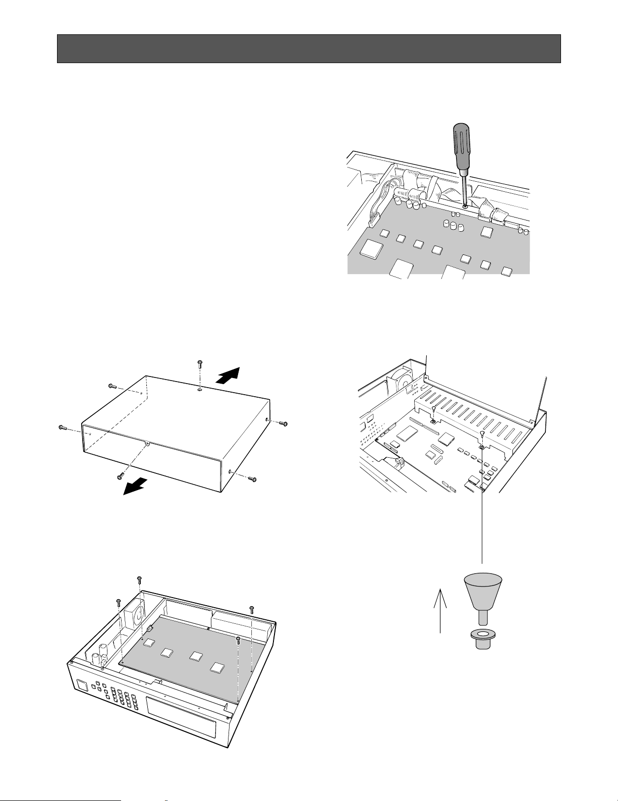
Caution: Before installing boards, be sure to turn
off the Power Switch of the video multiplexer.
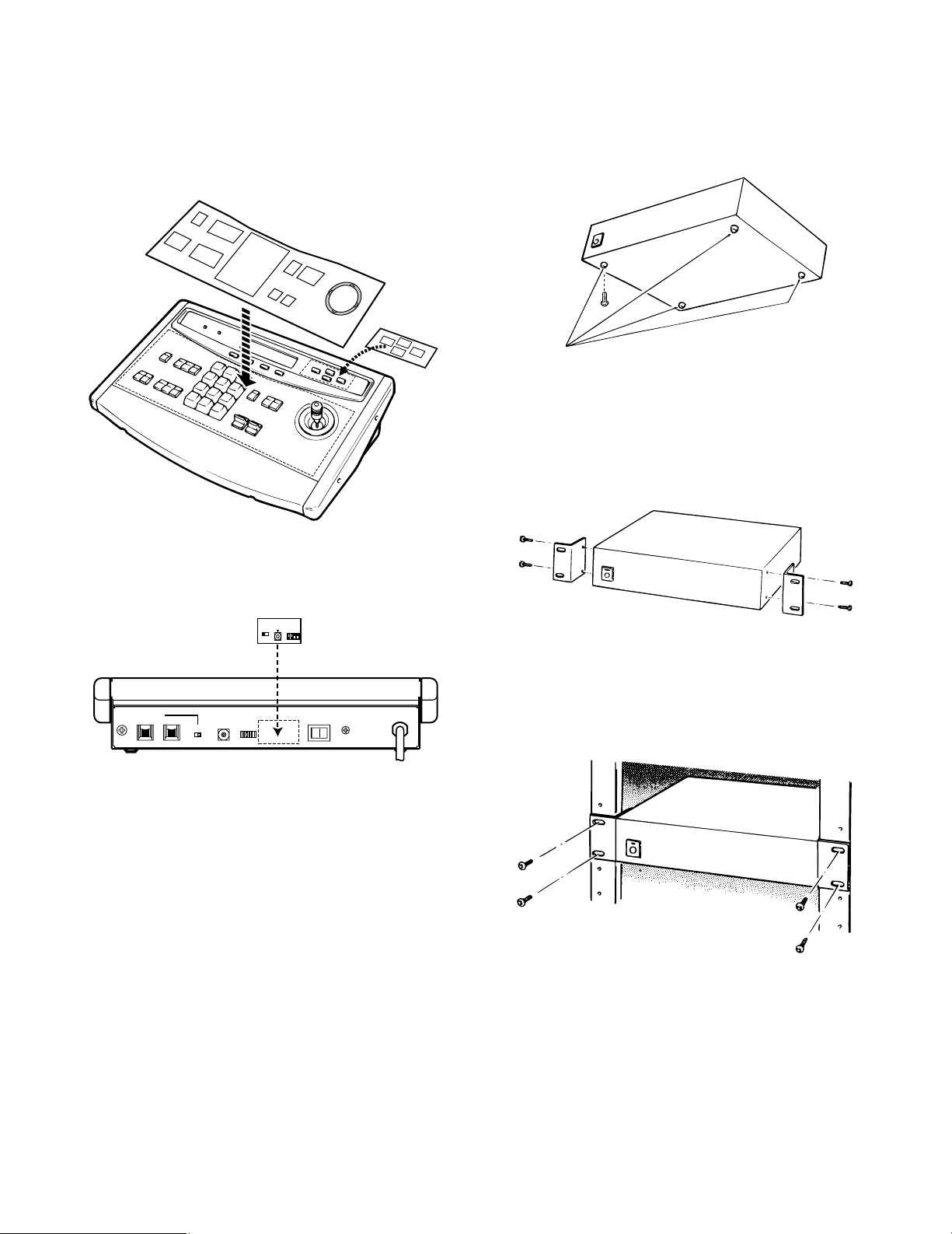
1. Remove the six screws on the top cover of the
video multiplexer as shown below.
2. Remove the top cover.
3. Remove the four screws on the board as shown
below.
4. Remove the one screw shown below. Then turn
over the printed circuit board with the front side up.
5. Pull out the two knobs from the bracket shown
below. Then remove the bracket.
Front
Rear
-11-
CH9 - CH16
CH1 - CH8
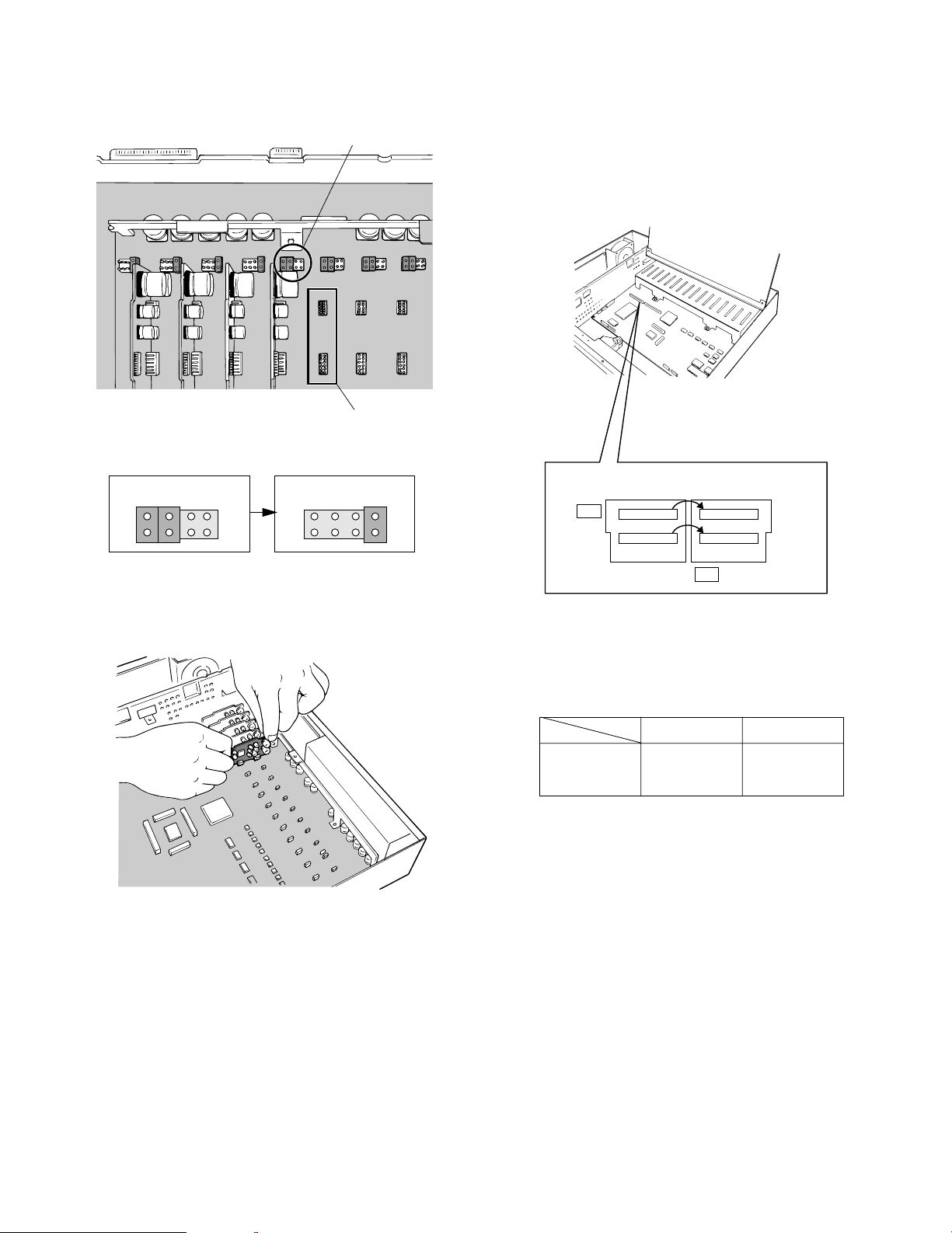
6. Set the jumper connector, located at the top left of
the board to be installed, to the position shown
below.
7. Insert the board and confirm that the position is correct. Then push it in straight.
8. After installing the boards, secure them by tightening the screws and knobs shown above.
Note: Some settings for the VD2 signal and control
data will be necessary from the setup menu of
the Video Multiplexer. Refer to Cable Compensation/VD2/Data Setup on page 34 for details.
Jumper Connector
Board Connector
Initial State Installed State
2
1
8
7
2
1
8
7
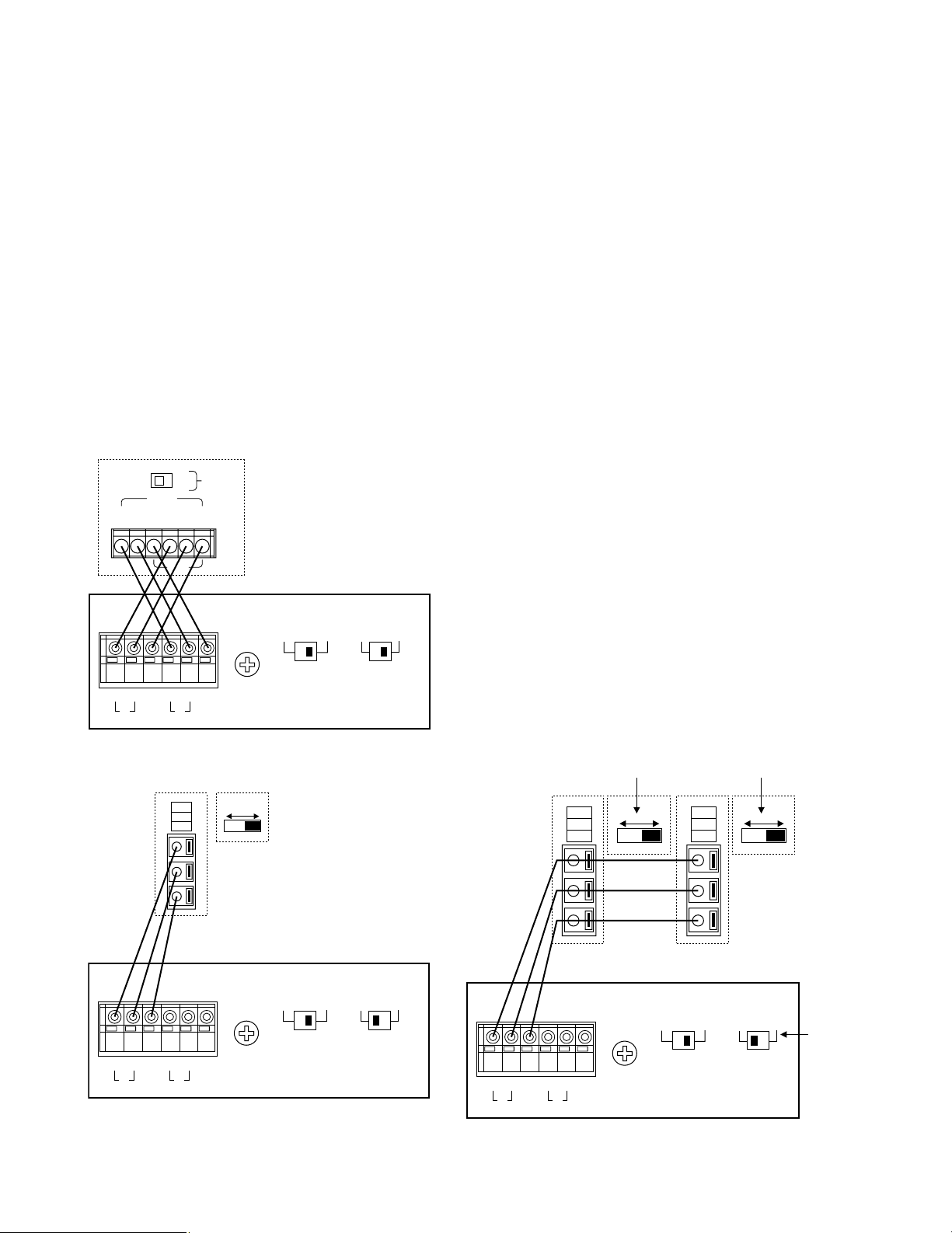
■ Tally Output Setting
Allows you to use the Alarm Input Terminal as Tally
Output Terminal by changing two internal connections.
1. Disassemble the video multiplexer as described for
installing the Data Multiplex Boards on page 10.
2. Move the two connectors from the ALM side to the
TLY side as shown above.
The relation between the connector numbers and
channel numbers is shown in the table below.
10 1
CN33
91
CN32
ALM
TLY
10 1
CN37
91
CN36
Alarm Input
CN33
CN32
Tally Output
CN37
CN36
-12-
■ Dip Switch Setting
● Alarm Output Setting
1. Disassemble the video multiplexer as described for
installing the Data Multiplex Boards on page 10.
2. Set switches (SW3/SW4/SW5) on the board to
choose the alarm control signals as either Open
Collector (O.C) or Pulse (0/5V).
Open Collector (O.C): 16V DC 100 mA max.
Pulse (0/5V): +5V DC approx. 500 ms
The above switch positions are the initial factory
settings.
0/5V O.C
SW5
0/5V 0/5V
SW3
O.C
SW4
O.C
SW3 : Alarm Output
SW4 : Alarm Reset Output
SW5 : Alarm & SW Output
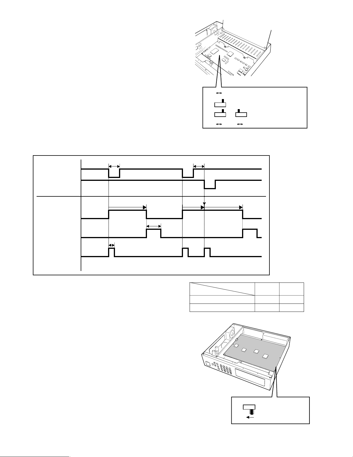
● Dummy Black Picture Setting
According to the initial factory setting, the Dummy
Black Picture signal is supplied to the REC OUT
connector as needed to overwrite any picture displayed by error. If this function is not required, set
the switch SW 1 to the position shown below.
1. Disassemble the video multiplexer as described for
installing the Data Multiplex Boards on page 10.
2. Set switch (SW1) on the board to the position
shown above.
Timing Chart of Alarm Output, Alarm Reset Output, Alarm and Switching Output (0/5 V Selected)
C If another alarm is input before the existing alarm is
reset, the alarm output lasts as long as the time set
for the succeeding alarm.
• The O.C position of SW3, SW4, and SW5 corresponds to their 0/5 V position as shown in the table
on the right side.
SW1
OFF
SW1 : Record Output
0VHi-Z Hi-Z Hi-Z
100 ms or more
Approx 100 ms
Approx.
450 ms
Alarm output time
0V
Alarm output time
C
Hi-ZHi-Z 0V
100 ms or more
Retrigger
5V
Alarm output
(Pin #9)
Alarm input 1
Alarm input 2
0V
5V
Alarm reset
output (Pin #27)
0V
5V
Alarm & SW
Output (Pin #25)
0V
O.C position
0/5 V position
Terminal condition
SW
OFF
Hi-Z
0 V
ON
0 V
5 V
-13-
■ WV-CU550A System Controller
● Modifying the Front Panel
1. Peel the tape off the supplied panel templates, then
attach them on the front panel of the System
Controller.
2. Peel off the label and attach it on the rear of the
System Controller as shown below.
CONTROLLER
ON
MODE
OFF
IN OUT
TERM
ON OFF
DATA
0
1
2
3
4
5
6
7
8
9
CONTROLLER
UNIT NO.
1-8
Connection with
Video Multiplexer
(WJ-FS616)
TERM. MODE
ON OFF
0
OFF
ON
■ WJ-FS616 Video Multiplexer
● Mounting in the Rack
1. Remove the four rubber feet by removing the four
screws on the bottom of the video multiplexer.
2. Place the rack mounting brackets on both sides of
the video multiplexer and tighten with the four supplied screws (M4 X10).
3. Install the video multiplexer with the rack mounting
brackets in the rack by using four screws (not
included).
Cautions:
• Do not block the ventilation opening or slots on
the cover to prevent the appliance from overheating.
Always keep the temperature in the rack within
45°C (113°F).
• Secure the rear of the appliance to the rack by
using additional mounting brackets (procured
locally) if the rack is subject to vibrations.
Remove 4 rubber feet
-14-
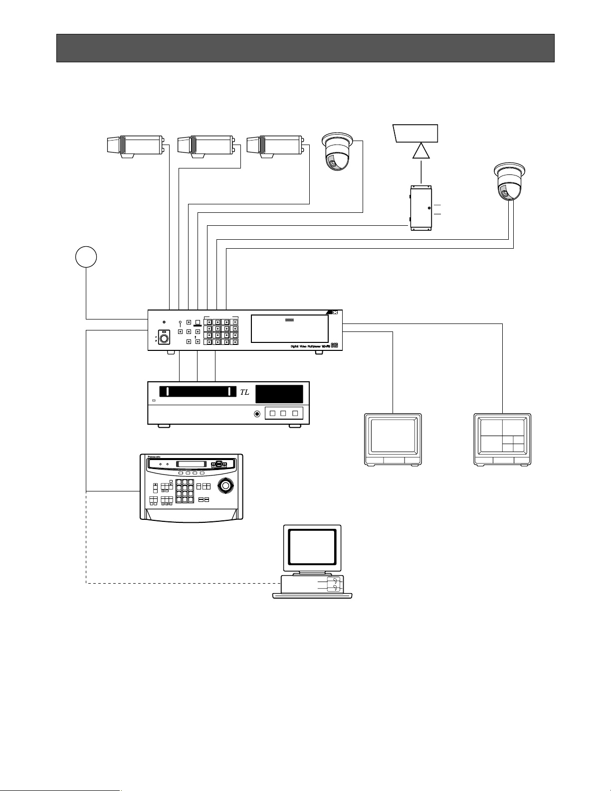
Basic System Connection
SYSTEM CONNECTIONS
Shown below is an example of a basic system connection.
AUX
Alarm
Alarm Sensor
Video
Data RS-485
Video Multiplexer
WJ-FS616
CAMERA/PRESET POSITION
MULTISCREEN
MULTI
ALARM
SELECT
SCREEN
LOCK
POWER
RESET SPOT SEQUENCE
ON
OFF
VCR
CAM
4
3
2
1
8
7
6
5
12
11
10
9
16
15
14
13
PUSH OPEN
16
RS-232C/Wired
Time Lapse VCR
1 2 3
4 5 6
7 8 9
MON CAM
0
F3 F4F2F1
System Controller for WJ-FS
616
Spot Monitor
Live 1-16ch
Multiscreen Monitor
Live 1-16ch
Playback 1-16ch
System Controller
WV-CU550A
Personal Computer
(Software)

-15-
CAMERA
IN
CAMERA
OUT
16 15 14 13 5 4 3 2 1
16 15 14 13 5 4 3 2 1
A BTA B
R
G
N
D
G
N
D
RS485
AUX
Alarm
Video Multiplexer WJ-FS616
■ Connection with the Camera Sites
Connect cameras (or camera site equipment) data
multiplexed type to the CAMERA IN connectors 1
through 4 on the rear panel of the Video Multiplexer.
Note: Make sure that the cable length between the
camera site and the WJ-FS616 Video Multi-plexer is less than 900 m (3 000 ft) when using RG59/U, BELDEN 9259 or equivalent cables.
Connect none multiplexed type cameras to the
CAMERA IN connectors 5 through 16.
Note: If you need to change input channels from
the none multiplexed type to multiplexed, install
the WV-PB6164 Data Multiplex Boards for the
corresponding channels inside the Video
Multiplexer. For installations, see page 10.
For cameras equipped with RS-485 communication
facility, connect the RS-485 cable as follows.
Note: If you use cables assembled from locally pro-
cured materials, it is important that only high
quality, data grade cable, suitable for RS-485
“2-wire twisted pair shielded cable” is used,
BELDEN 9406 or equivalent.
Low grade cable will result in unstable operation of the system.
Check the settings of the camera addresses when
using cameras capable of RS-485 communication.
Operations from the Multiplexer will not work if the
camera addresses are set improperly.
1. Do not use addresses other than 1 through 16 for
individual cameras (“17” is not allowed.)
2. Do not set the same address for more than one
camera in an RS-485 chain.
-16-
■ Connections for RS-485 type camera
There are two options to connect the camera with
the Multiplexer, depending on the distance
between them.
For data multiplexed type cameras, a maximum distance of 900 meters (3 000 ft) is the limit for using
coaxial cable such as RG-59/U, BELDEN 9259 or
equivalent.
If more distance is required, use cameras and
Multiplexers with RS-485 communication feature.
This will lower signal loss and extend the distance
as video signal and data are transmitted separately.
Note that you need to set up the communication
port as described on page 35 when using the RS485 feature.
Note: Recommended for RS-485 communication is
shielded, two-wire, twisted pair, low impedance
cable, AWG#22 or thicker.
(1) Connect with single RS-485 camera as shown
below, setting the LINE SELECT switch to “2” or “4”.
(2) Connect cameras in a Daisy Chain
1. Draw up a plan for connection between the cameras
and the input channels of the Video Multiplexer, and
the assignment of unit addresses to cameras.
Caution:
Check the settings of the camera addresses
when using cameras capable of RS-485 communication. Operations from the Multiplexer will
not work if the camera addresses are set
improperly.
1. Do not use addresses other than 1 through 16
for individual cameras (“17” is not allowed).
2. Do not set a single address for more than one
camera in an RS-485 chain.
2. Set the LINE SELECT switch of the Multiplexer to
“2”. Also set the switch of the connected equipment
if required.
3. Connect one end of the cable as shown to the RS485 terminal of the Multiplexer, and the other end to
the first camera in the chain. Repeat this procedure
for all cameras to the end of the chain.
4. Set the termination switches of the Multiplexer and
cameras at both ends of the chain to ON position.
Termination switches of cameras not at the chain
ends must be in OFF position.
Cautions:
• Termination is the key to data transmission and
reception in the chain. Only the switches at the
chain ends must be switched ON, while the
other switches are kept OFF.
• Response may slow gradually the higher the
equipment number in the chain.
ON
OFF
TERM
WJ-FS616
WV-RM70 and others
GND
DATA
T(A) T(B) R(A) R(B)
A B
T
A B
R
G
N
D
G
N
D
RS485 TERM.
LINE
SELECT
OFF ON 2 4
WJ-FS616
A BTA B
R
G
N
D
G
N
D
RS485 TERM.
LINE
SELECT
OFF ON 2 4
WV-CPR450 and others (For the
Termination Switch positions, refer
to the instruction manual for the
camera.)
(A)
(B)
GND
OFF ON
WJ-FS616
A BTA B
R
G
N
D
G
N
D
RS485 TERM.
LINE
SELECT
OFF ON 2 4
(A)
(B)
GND
OFF ON
(A)
(B)
GND
OFF ON
WV-CPR450 and others
Set it to
position 2
The switch on a daisychain-connected unit not
at the extremities must
be in the OFF position.
The switch on the end
unit should be in the
ON position.
(For the Termination
Switch positions, refer
to the instruction
manual for the
corresponding unit.)
-17-
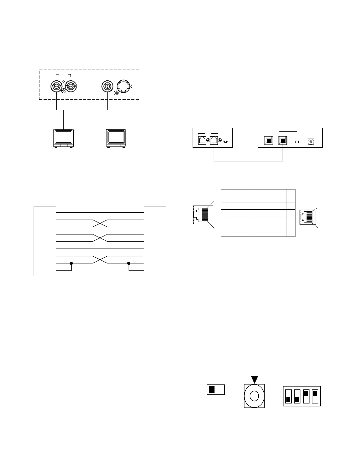
■ Connection with the Monitors
Connect the Monitors to the Spot Output (SPOT
OUT) Connector and Multiscreen (MULTISCREEN)
Connector on the rear of the Video Multiplexer.
■ Connection with the WV-CU550A
System Controller
If the supplied 6-conductor cable assembly is used,
simply plug one end of the cable into the DATA IN
port of the Video Multiplexer and the other end into
DATA OUT port on the System Controller.
If you use cables assembled from locally procured
materials, it is important that only high quality, data
grade cable, suitable for RS-485 “2-wire twisted
pair shielded cable” is used, BELDEN 9406 or
equivalent.
Low grade cable will result in unstable operation of
the system.
● Setting the Termination and Controller Unit
Number
The Termination Switch and the Controller Unit
Number Switch are located on the rear of the
System Controller.
When combined with the WJ-FS616 Video Multiplexer, always keep these switches in the positions
shown below.
● Setting the Mode Selection Switch
The Mode Selection Switch, that selects the operation mode of the System Controller, is located on
the rear of the System Controller.
When combined with the WJ-FS616 Video Multiplexer, always keep these switches in the positions
shown below.
SPOT
MULTISCREEN OUT
OUT I N
S–VIDEOVIDEO
Video Multiplexer
WJ-FS616
TERM. MODE
ON OFF
0
OFF
ON
TERM.
OFF
INOUT
ON
DATA
IN OUT
TERM
ON OFF
DATA
0
1
2
3
4
5
6
7
8
9
CONTROLLER
UNIT NO.
1-8
Video Multiplexer
WJ-FS616
System Controller
WV-CU550A
■ Connection with the PC
There are two options to communicate with the PC,
the first is using RS-232C port and the second is via
DATA port.
Connection with the WV-CU550A System Controller
RS-232C
• In page 2 of 2 of the SYSTEM SETUP menu, select
the RS-232C MODE and press the SET button to
activate the RS-232C port on the rear panel. Then
you need to select the parameters of the RS-232C in
the COM PORT SETUP menu detailed on page 35.
• Use a cross type RS-232C cable to connect the
Multiplexer with the PC.
DATA
In page 2 of 2 of the SYSTEM SETUP menu, select
the DATA MODE and press the SET button to activate the DATA port on the rear panel. Then you
need to select the parameters of the DATA in the
COM PORT SETUP menu detailed on page 35.
Use a 6-core modular cable to connect the Multiplexer with the PC.
Caution:
Data disruption may occur if you use both DATA
port and RS-232C port at a time. Use only one port
to communicate with the PC.
FG
TxD
RxD
RTS
CTS
SG
DTR
DSR
DCD
1
2
3
4
5
7
20
6
8
PC
FG
TxD
RxD
RTS
CTS
SG
DTR
DSR
DCD
1
2
3
4
5
7
20
6
8
FS616 end
1
6
1
6
No. No.
Name
Data Flow
1 1
GND
–
2 2
RX(B)
FS616 ← Controller
3 3
RX(A)
FS616 ← Controller
4 4
TX(B)
FS616 → Controller
5 5
TX(A)
FS616 → Controller
6 6
GND
–
Controller end
 Loading...