

Panasonic WJ-AV20 Operating Instructions Manual
Please read these instructions carefully before attempting
to connect or operate this product and be sure to save this manual for future use.
AVCodecAVCodec
AV Codec W
J-AV
20
R
E
M
O
T
E
R
IN
G
.V
O
L
PO
W
ER
ON
OFF
LINE
1
LINE
2
AV Codec
Operating Instructions
Model No. WJ-AV20
2
The serial number of this product may be found on the bottom of the unit.
You should note the serial number of this unit in the space
provided and retain this book as a permanent record of your
purchase to aid identification in the event of theft.
Model No.
Serial No.
WARNING:
To reduce the risk of fire or electric shock, do not expose this appliance to rain or moisture.
CAUTION: TO REDUCE THE RISK OF ELECTRIC SHOCK,
DO NOT REMOVE COVER (OR BACK).
NO USER-SERVICEABLE PARTS INSIDE.
REFER SERVICING TO QUALIFIED SERVICE PERSONNEL.
CAUTION
RISK OF ELECTRIC SHOCK
DO NOT OPEN
The lightning flash with arrowhead symbol, within an equilateral triangle, is
intended to alert the user to the presence
of uninsulated "dangerous voltage" within
the product's enclosure that may be of
sufficient magnitude to constitute a risk of
electric shock to persons.
The exclamation point within an equilateral triangle is intended to alert the user
to the presence of important operating
and maintenance (servicing) instructions
in the literature accompanying the appliance.
FOR YOUR SAFETY PLEASE READ THE FOLLOWING TEXT CAREFULLY.
This appliance is supplied with a moulded three pin mains plug for your
safety and convenience.
A 5 amp fuse is fitted in this plug.
Should the fuse need to be replaced please ensure that the replacement
fuse has a rating of 5 amp and that it is approved by ASTA or BSI to
BS1362.
Check for the ASTA mark
H or the BSI mark G on the body of the
fuse.
If the plug contains a removable fuse cover you must ensure that it is
refitted when the fuse is replaced.
If you lose the fuse cover the plug must not be used until a replacement
cover is obtained.
A replacement fuse cover can be purchased from your local Panasonic
Dealer.
IF THE FITTED MOULDED PLUG IS UNSUITABLE FOR THE SOCKET OUTLET IN YOUR HOME THEN THE FUSE SHOULD BE
REMOVED AND THE PLUG CUT OFF AND DISPOSED OF SAFELY.
THERE IS A DANGER OF SEVERE ELECTRICAL SHOCK IF THE
CUT OFF PLUG IS INSERTED INTO ANY 13 AMP SOCKET.
If a new plug is to be fitted please observe the wiring code as shown
below.
If in any doubt please consult a qualified electrician.
WARNING: This apparatus must be earthed.
IMPORTANT
The wires in this mains lead are coloured in accordance with the following code.
Green-and-yellow: Earth
Blue: Neutral
Brown: Live
As the colours of the wire in the mains lead of this appliance may not
correspond with the coloured markings identifying the terminals in your
plug, proceed as follows.
The wire which is coloured green-and-yellow must be connected to
the terminal in the plug which is marked with the letter E or by the earth
symbol
I or coloured green or green-and-yellow.
The wire which is coloured blue must be connected to the terminal in
the plug which is marked with the letter N or coloured black.
The wire which is coloured brown must be connected to the terminal
in the plug which is marked with the letter L or coloured red.
How to replace the fuse
Open the fuse compartment with
a screwdriver and replace the fuse
and fuse cover.
For U.K.
CAUTION:
Before attempting to connect or operate this product,
please read the label on the bottom.
Wij verklaren als enige aansprakelijke, dat het product waarop deze
verklaring betrekking heeft, voldoet aan de volgende normen of
andere normatieve documenten, overeenkomstig de bepalingen
van Richtlijnen 73/23/EEC, 89/336/EEC en 91/263/EEC.
Vi erklærer os eneansvarlige for, at dette produkt, som denne
deklaration omhandler, er i overensstemmelse med standarder eller
andre normative dokumenter i følge bestemmelserne i direktivene
73/23/EEC, 89/336/EEC og 91/263/EEC.
Vi deklarerar härmed värt fulla ansvar för att den produkt till vilken
denna deklaration hänvisar är i överensstämmelse med standarddokument, eller andra normativa dokument som framställs i EECdirektiv nr. 73/23, 89/336 och 91/263.
Ilmoitamme yksinomaisella vastuullamme, että tuote, jota tämä
ilmoitus koskee, noudattaa seuraavia standardeja tai muita ohjeellisia asiakirjoja, jotka noudattavat direktiivien 73/23/EEC,
89/336/EEC.ja 91/263/EEC säädöksiä.
Vi erklærer oss alene ansvarlige for at produktet som denne
erklæringen gjelder for, er i overensstemmelse med følgende
normer eller andre normgivende dokumenter som følger bestemmelsene i direktivene 73/23/EEC, 89/336/EEC og 91/263/EEC.
We declare under our sole responsibility that the product to which
this declaration relates is in conformity with the standards or other
normative documents following the provisions of Directives
73/23/EEC, 89/336/EEC and 91/263/EEC.
Noi dichiariamo sotto nostra esclusiva responsabilità che il prodotto
a cui si riferisce la presente dichiarazione risulta conforme ai
seguenti standard o altri documenti normativi conformi alle disposizioni delle direttive CEE/73/23, CEE/89/336 e CEE/91/263.
Wir erklären in alleiniger Verantwortung, daß das Produkt, auf das
sich diese Erklärung bezieht, mit der folgenden Normen oder normativen Dokumenten übereinstimmt. Gemäß den Bestimmungen
der Richtlinie 73/23/EEC, 89/336/EEC und 91/263/EEC.
Nous déclarons sous notre seule responsabilité que le produit
auquel se référe cette déclaration est conforme aux normes ou
autres documents normatifs conformément aux dispositions de la
directive 73/23/CEE, 89/336/CEE et 91/263/CEE.
Nosotros declaramos bajo nuestra única responsabilidad que el
producto a que hace referencia esta declaración está conforme con
las normas u otros documentos normativos siguiendo las estipulaciones de las directivas CEE/73/23, CEE/89/336 y CEE/91/263.

3
FEATURES .................................................................... 4
HOW TO USE THIS MANUAL ....................................... 4
PRECAUTIONS ............................................................. 5
MAJOR OPERATING CONTROLS
AND THEIR FUNCTIONS ....................................... 6
■ WJ-AV20 AV Codec ............................................... 6
■ WV-CU20E Remote Controller (Option) ................. 8
SYSTEM CONFIGURATION ........................................ 10
BEFORE STARTING OPERATION .............................. 11
■ Switching Power ON/OFF ..................................... 11
■ Information Displayed on Monitor ........................ 12
CALLING A SITE BY DIALING .................................... 13
■ Calling a Site by Directly Entering
a Telephone Number ........................................... 14
■ Calling a Site by Quick Dialing ............................. 16
■ Calling a Site by One-Touch Dialing .................... 17
■ Calling One Site After Another
by Sequential Dialing ........................................... 18
RECEIVING OPERATION DIAL-UP STANDBY ........... 20
OPERATION DURING COMMUNICATION ................. 22
■ Switching Video to Transmit ................................. 22
■ Muting Audio to Transmit ..................................... 23
■ Combination Camera Operation .......................... 23
ALARM VIDEO CHECK DIAL-UP STANDBY .............. 24
■ How to Check ....................................................... 25
SETUP PROCEDURES ................................................ 27
MENU OPERATING PROCEDURES ........................... 28
■ How to Use the Controller .................................... 28
■ Basic Menu Operation ......................................... 28
SYSTEM SETUP .......................................................... 30
■ Mode Setup [100] ................................................ 30
■ Receiving Registration [200]................................ 31
● Receiving Method Setup [210] ........................ 31
● Local Number Registration [220] ..................... 32
● Calling and Called Number Checks [230] ....... 33
● Group ID Check [240] ...................................... 33
■ Directory/Dialing Registration [300] ..................... 34
● Quick (Short) Dial Registration [310] ............... 35
● One-touch Dial Number Assignation [320] ...... 36
● Sequential Dialing Methods [330] .................... 37
■ System Setup [400] .............................................. 38
● Clock Setup [410] ............................................ 39
● Serial Data and Host Port Setup [420] ............. 40
● Serial Data Port Setup [421] ............................. 40
● Host Port Setup [422] ....................................... 41
● View Point Setup [430] .................................... 42
● Audio Setup [440] ............................................ 44
● Video Setup [450] ........................................... 45
● Video Motion Mode Setup [451] ..................... 45
● On-screen Display Setup [452] ....................... 46
● Cable Compensation Setup [453] ................... 47
● Alarm Setup [460] ........................................... 48
● Alarm Setup [461] ............................................ 50
● Alarm Dialing Tables Setup [462, 463, 464] .... 50
● Sequential Scan Setup [470] .......................... 51
● Alarm Memory Method Setup [480] ................. 51
● Lock/Password Setup [490] ............................. 52
● Lock Item Setup [491] ...................................... 52
● Menu Password Setup [492] ............................ 53
CHANGING SETTINGS DURING COMMUNICATION 54
■ Remote Control Setup [500] ................................. 54
● Camera, Preset, Trigger Out Switching [510] .. 55
● Video Motion Setup [520].................................. 56
HOW TO USE THE MAINTENANCE FUNCTION ........ 57
■ Maintenance [600] ............................................... 57
● Alarm Log [610] ............................................... 58
● Alarm Log (Transmitter) .................................. 58
● Alarm Log (Receiver) ....................................... 59
● Remote Site Clock Setup [620] ........................ 59
●Communication Rate
/Information Verification [630] ........................ 59
● Calling Log Display [640] ................................. 60
● Called Log in Com. .......................................... 60
● Calling Log ....................................................... 60
● Serial Data Port Setup Verification [650].......... 61
● Local Loopback/Loopback Request [660] ...... 61
● Loopback Test at Local Site (Local Loopback) 61
● Loopback Test with Connected Site
(Loopback Request) ........................................ 62
● Version Verification [670] ................................. 62
● Mode Verification [680] .................................... 63
● Initialize [690] ................................................... 63
HOW TO USE THE REMOTE SETUP FUNCTION ....... 64
■ Remote Setup Edit [700] ...................................... 64
INSTALLATION MANUAL ........................................... 66
BEFORE STARTING WORK ........................................ 67
CONNECTIONS .......................................................... 68
■ Standard System Configuration ........................... 68
■ Example of Connections with Video
Quad Unit or Sequential Switcher ........................ 71
■ Example of Connections with Matrix
Switcher or Video Multiplexer ............................... 72
RACK MOUNTING ...................................................... 75
TROUBLESHOOTING ................................................. 76
OPTIONAL ACCESSORIES ......................................... 81
APPENDIX ................................................................... 81
■ For Personnel Attending to ISDN Line Work ........ 82
SPECIFICATIONS ....................................................... 83
STANDARD ACCESSORIES ....................................... 84
■ Specifications for Sensor Input/Trigger
Output Terminals .................................................. 85
■ Specifications for Parallel Ports ............................ 85
■ Specifications for Setting Dip Switches ............... 86
■ Host Port (RS-485/RS-232C) ................................ 86
■ Data Port .............................................................. 86
INDEX .......................................................................... 87
CONTENTS

4
FEATURES
● A remote surveillance system can be built to monitor
unattended stores and remote places.
• Video, audio and digital data can be transmitted
and received through ISDN (1 line).
• High-quality video can be transmitted and received
by the H.261 or H.263 (ITU standard) system.
Note: Mutual connection with other codec manufac-
tures is not guaranteed.
• Audio can be clearly received because an echo
canceler is built in.
● May be combined with a sensor for automatic dialing.
Up to 100 alarm log items can be verified.
• Sensor input port is located on the rear of the AV
Codec. Using this sensor input port, a set telephone
number may be dialed when an externally installed
sensor has operated, thus transmitting video and
audio data.
● Up to 5 one-touch dial numbers and 200 quick (short)
dial numbers can be registered. Automatic surveillance
by sequential dialing is also available.
• By simply pressing a one-touch dial button, the registered site of the corresponding number can be
called.
• By registering numbers frequently dialed in the
directory, their sites can be called by a simple step.
If the sequential dialing function is set to ON when
registering quick dial numbers, the registered quick
dial numbers will be automatically dialed in
sequence for surveillance.
● Up to 5 cameras can be connected.
• There are 5 video input terminals. A Panasonic
combination camera can be connected to video
input terminal 1, through which the pan/tilt head
can be controlled for pan/tilt, zoom and focus.
• Up to 8 view points (video points to monitor) can be
set.
• Panasonic monitor devices can be easily connected to the RS-485 data port in configuring a system
suited to a particular use.
● Video storage function capable of recording motion
pictures before sensor input
• Video data before and after an alarm is detected
by the sensor can be stored in the internal memory
of the AV Codec at the transmitter site. (Video storage function) The stored video can later be transferred to the receiver for verification.
● Versatile maintenance function (remote setup and trouble analysis)
• The settings at an unattended site can be changed
from the control site.
• Various kinds of recorded information helpful for
trouble analysis can be displayed on the monitor
for verification.
• Operation by unauthorized persons can be prevented by protecting the settings with a password.
HOW TO USE THIS MANUAL
ISDN and other PBX networks are called dial-ups in this
manual. The following symbols are used in the descriptions
given in the manual.
: Item for operation or setup at a remote
site (transmitter) only
: Item for operation or setup at a control
site (receiver) only
: Item for operation or setup in case of
using line exchange
Dial-Up
Receiver
Transmitter
: Item for operation or setup during
line exchange standby only
Dial-Up Standby

5
• Refer all work related to the installation of this
product to qualified service personnel or system
installers.
• Do not drop metallic parts through slots.
This could permanently damage the appliance. Turn
the power off immediately and refer servicing to
qualified service personnel.
• Do not attempt to disassemble the appliance.
To prevent electric shock, do not remove screws or
covers.
There are no user-serviceable parts inside. Refer maintenance to qualified service personnel.
• Handle the appliance with care.
Do not strike or shake it, as this may damage the appliance.
• Fully charge up the backup battery.
Keep the appliance turned on for at least 48 hours to
recharge the backup battery. This procedure is necessary when using the appliance for the first time or after
it has been unplugged for a long time from the AC outlet. Insufficient battery charging may cause erasure of
settings if the AC power supply should fail. The battery,
if fully charged, will back up the settings for 72 hours in
an ordinary environment.
• Do not expose the appliance to water or moisture,
nor try to operate it in wet areas.
Take immediate action if the appliance becomes wet.
Turn the power off and refer servicing to qualified service personnel. Moisture can damage the appliance
and also cause electric shock.
• Do not use strong or abrasive detergents when
cleaning the appliance body.
Use a dry cloth to clean the appliance when it is dirty.
When the dirt is hard to remove, use a mild detergent
and wipe gently.
• Do not operate the appliance beyond its specified
temperature, humidity or power source ratings.
Do not use the appliance in an extreme environment
where high temperature or high humidity exists.
Use the appliance at temperatures between –10°C +50°C (14°F - 122°F) and at humidity below 90 %.
The input power source for this appliance is 220 - 240 V
AC 50 Hz.
PRECAUTIONS

q Power Switch (POWER, ON / OFF)
This switch is used to turn the WJ-AV20 AV Codec
power on and off.
The LED indicator lights up while the codec power is
turned on.
Note: To prevent the AC Codec power from being
turned off accidentally, install the supplied switch
protector as shown below.
w Controller Jack (REMOTE)
This jack is provided for controlling the AV Codec with
the WV-CU20E Remote Controller.
SIGNAL GND
AC IN
OFF ON
RS–485
RS–232C
ON
↓
654321
112
245
3
OUT
IN
TEST
SETUP
REMOTE DATA PORT HOST PORT
HOST PORT
VIDEO
IN OUT
TERM
SENSOR IN/TRIGGER OUT
PARALLEL PORT
ISDN
1
2
REMOTE
LOCAL
AUDIO
!1 !3 !4 !6
!7 !8 !9!5!2 @0 @1 @2 @3
@4 @5 @6 @7
6
MAJOR OPERATING CONTROLS AND THEIR FUNCTIONS
LINE1LINE
2
RING.VOL
AV Codec WJ–AV
POWER
ON
OFF
REMOTE
qwr
et
■ WJ-AV20 AV Codec
● Front View
● Rear View
To connect the controller, use a 6-conductor DIN cable
supplied as an accessory with the controller.
If the controller is connected to the REMOTE port on the
rear of the AV Codec, use a 6-conductor modular cable
supplied as an accessory with the controller.
e Line Indicators (LINE1/LINE2)
Indicates when the line is being used.
r Ringer Volume Control (RING VOL)
This control is used to adjust the alert tone to the
desired level for receiving calls.
t Ringer Buzzer
SWITCH
PROTECTOR

7
!1 Video Input Connectors (VIDEO IN, 1 - 5)
These connectors accept composite video signals from
cameras.
When the Panasonic combination camera is connected
to the VIDEO IN 1 connector, various controls, such as
pan/tilt, zoom, focus and preset, are enabled from the
WV-CU20E Remote Controller connected to the AV
Codec.
The above functions are only available when a camera
equipped with the specified function is connected to
the VIDEO IN 1 connector.
!2 Local Output connector (LOCAL)
The video signals, VIDEO IN 1 - 5, selected by the controller are looped through to this connector.
When the Video Monitor is connected to this, it displays
the camera images at the local site selected by the
controller.
!3 Remote Output Connectors (REMOTE, 1 - 2)
The video signals, that are stored in the internal memory, are output to these connectors.
When the video monitors are connected to these connectors, the slow motion and poor resolution images
are displayed.
They also enable and disable the image display as
shown below.
REMOTE 1: Enables display, such as setup menu,
clock, etc.
REMOTE 2: Disables all on screen display.
!4 Audio Input Connector (AUDIO IN)
Accepts audio signal from the outboard device. It is
transmitted to the AUDIO OUT connector of the AV
Codec at the destination site.
During transmission, when the AUDIO MUTE button on
the controller is pressed, audio transmission is temporarily interrupted. Press the button again to release
the mute mode.
!5 Audio Output Connector (AUDIO OUT)
Outputs the audio transmitted from the destination site.
Enabling or disabling audio output depends on the settings at the destination site.
The audio input at the local site cannot be to output
through this connector.
!6 Test Switch / Test LED (TEST)
The maintenance (test) switch and LED should not be
manipulated in ordinary operation.
!7 Controller Port (REMOTE)
This port is provided for controlling the AV Codec with
the WV-CU20E Remote Controller.
To connect to the controller, use a 6-conductor modular cable supplied as an accessory with the controller.
!8 Data Port (DATA PORT)
Accepts a 6-conductor modular cable to exchange
data conforming to an RS-485 interface.
It can be used to establish a system by connecting to
outboard devices.
!9 Setup Switches (SETUP)
These switches are used to select the mode of the AV
Codec, such as line termination.
Refer to the DIP Switch Setting for further details.
@000 RS-485 Host Port (RS-485 HOST PORT)
This port is used when multiple WJ-AV20 units are controlled with a single control unit (PC, etc.).
@1 RS-232C Host Port (RS-232C HOST PORT)
This port is used when the WJ-AV20 is controlled with a
PC, etc.
Use a crossover cable for connecting to the PC port.
@22 Termination Selector (TERM, ON/OFF)
This switch is used to enable termination of the ISDN
line.
Setting to the ON position will make an internal 100 Ω
termination.
@3 ISDN Port (ISDN)
This port is used to connect with an ISDN line, using 8conductor modular cable supplied as an accessory
with the AV Codec.
@44 Sensor Input / Trigger Output Port (SENSOR
IN/TRIGGER OUT)
This port is used when the AV Codec is used as a
transmitter (remote site).
It enables alarm dialing or camera switching when the
associated alarm sensor is connected to this port.
When the trigger output is connected to an outboard
device, such as a switcher, camera switching is
remotely enabled from the AV Codec.
@55 Parallel Port (PARALLEL PORT)
Exchanges 8-bit input and 8-bit output data with the
destination (with strobe output).
This port is also provided with pins so that the signals
shown below can be exchanged.
• Forced Disconnection input
• Time Adjustment input
@6 Signal Ground
@7 AC Inlet Socket (AC IN)
Plug the power cord (supplied as a standard accessory) into this socket and connect it to an AC outlet.
8
ESC
MENU
AF NEAR FARTELE WIDE
Remote Controller WV-CU20
123
456
7809
12345
#
STEP 1
DIAL
MEMORY
STEP 2 STEP 3
CALL
REDIAL
DELETE
ENTER
AUDIO MUTE
ALM ACKVIDEO
ONE TOUCH DIAL
AUTO/MANU
ALM MEMORY
SER
NO.
#5
#4
$1
$0
$4
$3
$2
#1
#2
#3
#6
#7
#9
%1
%2
#8
$5
$6
$7
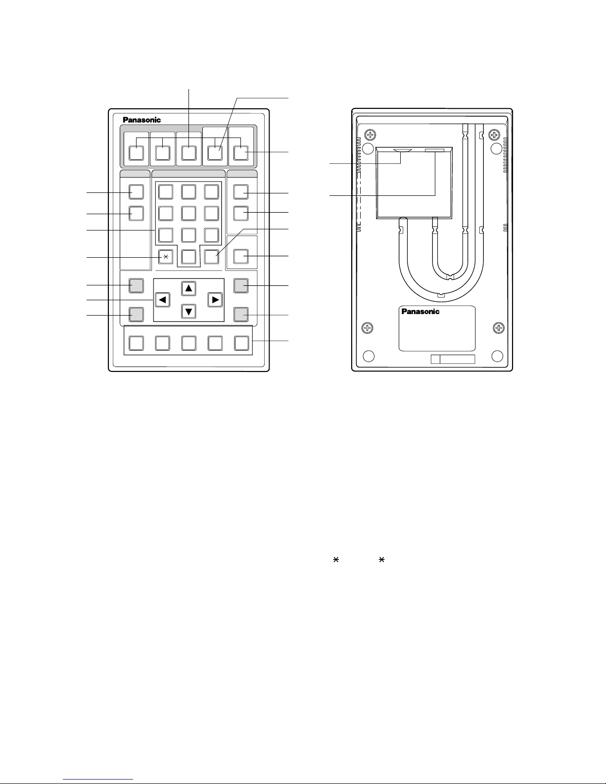
■ WV -CU20E Remote Controller (Option)
#1 One-touch Dial Buttons (ONE TOUCH DIAL, 1 - 5)
This button, in combination with the Dial button, is used
to call the destination that was previously assigned to
that button.
#2 Video Scanning Mode Button
(VIDEO AUTO/MANU, 4)
This button is used to toggle the scanning mode automatically and manually.
#3 Alarm Acknowledge Button (ALM ACK, 5)
This button is used to acknowledge activated alarms.
#4 Quick Dial Button (MEMORY)
This button is used to select Quick (Short) Dial numbers
stored in the menu.
#5 Dial Button (DIAL)
This button is used to dial calls in combination with the
CALL button.
#6 Call Button (CALL)
This button is used call destinations.
#7 Redial Button (REDIAL)
This button is used to automatically redial the destination last called.
#8 Delete Button (DELETE)
This button is used to correct any numeric or alphabetic
input in the menu.
Pressing this button will delete the character positioned
immediately to the left of the cursor.
#9 # (Alarm Memory) Button (# ALM MEMORY)
This button is used to request an alarm video at the
destination site.
It is also used to play back alarm videos stored in the
internal memory.
$0 Button ( )
This button is used to toggle the camera image display
manually on the monitor with the view points assigned.
$1 Numeric Buttons (0 - 9)
These buttons are used for numeric input into the system, including phone numbers, passwords, and camera selection.
$2 Menu Button (MENU)
This button is used to open the setup menu on the monitor screen.
Pressing it again will close the menu.

9
$3 Direction Buttons (t▲s▼)
These buttons are used to operate the Pan/Tilt head
manually when a camera equipped with the specified
function is connected to the VIDEO IN 1 on the rear of
the AV Codec. They will also move the cursor to the
desired position while the menu is displayed on the
monitor screen.
$4 Escape Button (ESC)
This button is used to escape and execute the currently
highlighted setting on the setup menu. The monitor
screen will then return to the previous setup menu.
$5 Audio Mute Button (AUDIO MUTE)
This button is used to mute the outgoing sound from the
local site.
Pressing it again will restore the sound.
$6 Enter Button (ENTER)
This button is used to execute a selection or access the
submenu of the selected item menu.
$7 Camera Control Buttons
These buttons are used to control any camera
equipped with the specified function that is connected
to the VIDEO IN 1 on the rear of the AV Codec.
TELE / WIDE: Adjusts camera lens zoom.
AF: Adjusts camera lens focus automatically.
NEAR / FAR: Adjusts camera lens focus.
%1 Connection Jack
This jack is used to connect with the Controller Jack on
the front of the WJ-AV20 AV Codec.
To connect to the codec, use a 6-conductor DIN cable
supplied as an accessory with the controller.
%2 Connection Port
This port is used to connect with the Controller Port on
the rear of the WJ-AV20 AV Codec.
To connect to the codec, use a 6-conductor modular
cable supplied as an accessory with the controller.

10
A standard system configuration for using the WJ-AV20 AV Codec is shown below.
• One AV-Codec is necessary for a remote site (transmitter) and another for a control site (receiver). The setup menu may
be used for setting change a transmitter to a receiver or vice versa. Before starting operation, check the settings.
• Cameras connected to the remote site can be switched as necessary to monitor them from the control site.
• An agreement is necessary for using ISDN lines.
• A DSU (Digital Service Unit, a line connecting unit) is also necessary.
• The optional WV-CU20E Remote Controller is necessary for system operation.
• In addition, sensors, personal computers, etc. may be added to configure a system suited to the environment.
DSU
STEP2 STEP3
DIAL
MEMORY
CALL
REDIAL
DELETE
ESC
AUDIO MUTE
MENU
ALM MEMORY
ENTER
TELE WIDE
AF
NEAR
FAR
STEP1
Remote Controller WV-CU20
123
456
7809
12345
#
VIDEO
AUTO/MANU
ALM ACK
ONE TOUCH DIAL
LINE1LINE
2
RING.VOL
AV Codec WJ–AV
POWER
ON
OFF
REMOTE
LINE1LINE
2
RING.VOL
AV Codec WJ–AV
POWER
ON
OFF
REMOTE
Example of a system with 1 combination camera
and 4 colour or black and white cameras connected
Combination camera
Colour/black and white camera
Automatic fire alarm,
proximity sensor
AV Codec
for remote site
Transmitter mode
DSU
ISDN
AV Codec
for control site
Receiver mode
Video Monitor
Controller
In Case of Using a Panasonic Matrix Switcher with the AV Codec
Observe the following precautions when using a Panasonic matrix switcher connected to a remote site.
• To operate the matrix switcher and the devices connected to the matrix switcher, use the system controller (WVCU550A) exclusive to the matrix switcher.
• After communication starts, be sure to perform the log-in operation with the WV-CU550A before operating the matrix
switcher.
• Before terminating communication, be sure to perform the log-out operation with the WV-CU550A.
• If the matrix switcher is switched back on after communication is over, then the matrix switcher will be unable to be
operated again from the next call. In such a case, switch the system controller back on.
For the operating instructions for the matrix switcher and system controller, refer to the relevant manuals.
SYSTEM CONFIGURATION
11
BEFORE STARTING OPERA TION
c
c
STEP2 STEP3
DIAL
MEMORY
CALL
REDIAL
DELETE
ESC
AUDIO MUTE
MENU
ALM MEMORY
ENTER
TELE WIDE
AF
NEAR
FAR
STEP1
Remote Controller WV-CU20
123
456
7809
12345
#
VIDEO
AUTO/MANU
ALM ACK
ONE TOUCH DIAL
LINE1LINE
2
RING.VOL
POWER
ON
OFF
REMOTE
3
When you are not using the AV Codec for a long period of
time, press the power switch off and remove the power plug
from the AC outlet.
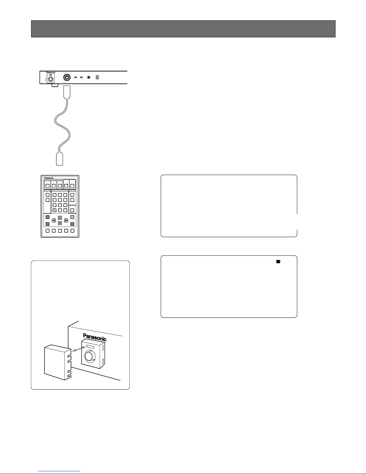
■ Switching Power ON/OFF
1
Connect the Remote Controller to the AV Codec.
Connect the WV-CU20E remote controller to the controller jack or port on
the front or rear of the AV Codec.
2
Press the power switch on.
• When power is switched on, the power indicator lights up.
• The blue screen appears first after power is switched on. The present time
is shown on the monitor in about 10 seconds, and the AV Codec is in a
standby state and is ready for operation.
■CLOCK
01/01/99 MON 00:00:00
PLEASE SET DATE.TIME IN CLOCK
SETUP MENU 410.
VIDEO1 01/01/99 00:00:00
TITLE
Connect the remote
controller to the AV
Codec with the cable
supplied with the controller. (Use the 6-conductor DIN cable to
connect it to the front
of the AV Codec, or
the 6-conductor modular cable to connect
it to the rear.)
Normally, keep the power switch
in the ON position during use.
When the power switch is pressed
off, calls cannot be originated or
received. Normally, keep the power
switch in the ON position and install
the supplied switch protector over
the power switch.
SWITCH
PROTECTOR
d
Standby screen appears in about 10
seconds.
If the date and time are incorrect, then
correct them using the setup menu.
12
100 MODE
MODE : TRANSMITTER RECEIVER
←→:SELECT ESC:PRV
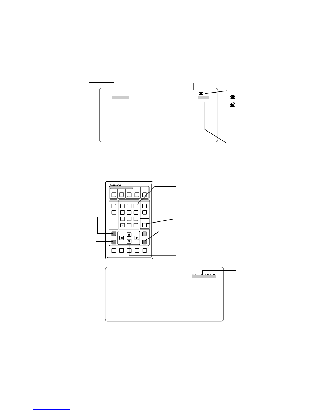
■ Information Displayed on Monitor
Operate the AV Codec according to the information displayed on the monitor. Here is a description of the information on the
monitor.
● Basic Information
VIDEO1 01/01/99 00:00:00
MUTE
View point number (Control site
shown during communication only)
TITLE registered in directory is
shown during communication. (Not
shown if not registered)
Date and present time
Telephone symbol
: Standby
: Communicating
Communicating state (Goes out
about 10 seconds after start of
communication)
● :1B connection
●● : 2B connection
Mute
● Screen Operation
STEP2 STEP3
DIAL
MEMORY
CALL
REDIAL
DELETE
ESC
AUDIO MUTE
MENU
ALM MEMORY
ENTER
TELE WIDE
AF
NEAR
FAR
STEP1
Remote Controller WV-CU20
123
456
7809
12345
#
VIDEO
AUTO/MANU
ALM ACK
ONE TOUCH DIAL
To move the cursor
Numeric buttons to enter numbers
and menu item numbers
To delete input data, or to delete the character positioned
immediately to the left of the cursor
To enter a selected item; to display the next screen.
Cursor (blinking)
Use the controller to perform operations on the screen.
To open or close the setup
menu
To return to previous menu
To execute the currently highlighted setting and return to the
previous menu

13
Only one site can be connected. Two or more sites cannot be called at the same time.
Note
There are various ways of calling a site by dialing as follows:
(1) Enter a telephone number to call a site.
(2) Call a site by one-touch dialing.
Press the DIAL button and then press a ONE TOUCH DIAL button to call the corresponding registered site.
One site can be registered for each ONE TOUCH DIAL button. It is convenient if the telephone numbers of frequently
called sites are registered in advance.
(3) Call a site by dialing a quick dial number.
A site can be called without entering the telephone number if it is registered in the directory in advance.
Up to 200 quick dial numbers can be registered in the directory.
(4) Sites can be called in turn by sequential dialing (with monitor points automatically switched from one to another). To make
sequential dialing effective, the sequential dial function must be set to ON when registering the quick dial numbers of sites
in the directory.
STEP2 STEP3
DIAL
MEMORY
CALL
REDIAL
DELETE
ESC
AUDIO MUTE
MENU
ALM MEMORY
ENTER
TELE WIDE
AF
NEAR
FAR
STEP1
Remote Controller WV-CU20
123
456
7809
12345
#
VIDEO
AUTO/MANU
ALM ACK
ONE TOUCH DIAL
LINE1LINE
2
RING.VOL
AV Codec WJ–AV
POWER
ON
OFF
REMOTE
LINE1LINE
2
RING.VOL
AV Codec WJ–AV
POWER
ON
OFF
REMOTE
LINE1LINE
2
RING.VOL
AV Codec WJ–AV
POWER
ON
OFF
REMOTE
LINE1LINE
2
RING.VOL
AV Codec WJ–AV
POWER
ON
OFF
REMOTE
Press DIAL button, and
then press a ONE TOUCH
DIAL button to call.
Quick dialing
q Press MEMORY button.
w Enter a quick dial number
(001 to 200).
e Press ENTER button.
r Press CALL button.
Direct input of a telephone
number
q Press DIAL button.
w Enter a telephone number.
e Press CALL button.
To terminate communication,
press DIAL button for
2 seconds or more.
ON
OFF
POWER
AV Codec (transmitter)
for remote site
Point A
AV Codec (transmitter)
for remote site
Point B
AV Codec (transmitter)
for remote site
Point C
ISDN
Sensor
AV Codec (receiver)
for control site
Remote controller
CALLING A SITE BY DIALING

14
STEP2 STEP3
DIAL
MEMORY
CALL
REDIAL
DELETE
ESC
AUDIO MUTE
MENU
ALM MEMORY
ENTER
TELE WIDE
AF
NEAR
FAR
STEP1
Remote Controller WV-CU20
123
456
7809
12345
#
VIDEO
AUTO/MANU
ALM ACK
ONE TOUCH DIAL
1
Press the DIAL button.
[■ DIAL] menu appears on the monitor screen.
2
Enter the telephone number of the site you wish to call, by
pressing the numeric buttons.
• For 1B (64 Kbits/s) connection, enter the telephone number on the 1B line
only.
• For 2B (128 Kbits/s) connection, enter it on both the 1B and 2B lines. (Also
enter a sub-address if you wish to specify it.) The entered data on the 1B
line can be copied on the 2B line by pressing the ENTER button after filling
in the 1B line.
• The input data can be corrected by pressing the DELETE button. The character positioned immediately to the left of the cursor is deleted when the
DELETE button is pressed.
3
Press the [CALL] button.
[■ DIRECT DIALING] menu appears on the monitor screen, indicating that
dialing has started.
To Correct
By pressing the DELETE button,
the character positioned immediately to the left the cursor can be
deleted.
After deleting the wrong number,
enter the correct one with the
numeric buttons.
■DIAL
DIAL#:
1B :
SUB:
2B :
SUB:
ENTER DIAL NUMBER, THEN PRESS CALL
KEY, DIALING,
↑↓←→:MOVE CALL:CALL DEL:BS
ONE TOUCH DIAL:CALL REDIAL:CALL
ENT:NO. COPY(1B→2B)DIAL/ESC:CLEAR
■DIRECT DIALING
NO: ◆◆◆◆◆◆◆◆◆◆◆◆◆◆◆◆◆◆◆◆◆◆◆◆◆◆◆◆◆◆◆◆
SUB:◆◆◆◆◆◆◆◆◆◆
CONNECTING ●●
DIAL/ESC:CANCEL
1
4
2
3
No. being connected
Sub-address being connected
Line speed
● 64Kbit/s
●● 128Kbit/s
Line 1 or 2 lights green: 64 K bits/s
Line 1 and 2 light green: 128 K bits/s
LINE1LINE
2
RI
POWER
ON
OFF
REMOTE
Dialing at 2B
If a site to be called uses neither 1B nor 2B, it can be dialed at 2B. If a
site engaged in communication at 1B is dialed at 2B, however, the call
is disconnected. Either wait a while and then call again, or dial again at
1B.
■ Calling a Site by Directly Entering a Telephone Number

15
4
Press the DIAL button for 2 seconds or more to terminate
the call.
The line is disconnected to terminate the call. [■ LINE TERMINATED]
menu appears on the monitor screen.
It will be closed automatically after 10 seconds.
■LINE TERMINATED
◆◆◆◆◆◆◆◆◆◆◆◆◆◆◆◆◆◆◆◆
#### ◆◆◆◆◆◆◆◆
ESC:CLEAR
Cause code: #016 always means the normal
end of communication. If an error occurs,
then the cause code and the reason will be
shown together.

16
STEP2 STEP3
DIAL
MEMORY
CALL
REDIAL
DELETE
ESC
AUDIO MUTE
MENU
ALM MEMORY
ENTER
TELE WIDE
AF
NEAR
FAR
STEP1
Remote Controller WV-CU20
123
456
7809
12345
#
VIDEO
AUTO/MANU
ALM ACK
ONE TOUCH DIAL
1
2
3
1
Press the MEMORY button.
[■ QUICK DIAL] menu appears on the monitor screen.
2
Enter a quick dial number by pressing the numeric buttons.
• Enter a desired number from 001 to 200.
• When the ENTER button is pressed after entering the quick dial number,
then the registered quick dial numbers are shown in the Directory column.
• A quick dial number can also be selected by moving the cursor to the number in the Directory column and pressing the ENTER button. An item can
be selected using the [▲] or [▼] button.
• An input quick dial number can be corrected using the DELETE button. (It
cannot be corrected after pressing the ENTER button.) The character
immediately preceding the cursor is deleted when the DELETE button is
pressed.
■QUICK DIAL
QUICK#
NO.### ◆◆◆◆◆◆◆◆◆◆
DIAL#(1B):
◆◆◆◆◆◆◆◆◆◆◆◆◆◆◆◆◆◆◆◆◆◆◆◆◆◆◆◆◆◆◆◆
DIRECTORY:
◆◆◆ ◆◆◆◆◆◆◆◆◆◆
◆◆◆ ◆◆◆◆◆◆◆◆◆◆
◆◆◆ ◆◆◆◆◆◆◆◆◆◆
◆◆◆ ◆◆◆◆◆◆◆◆◆◆
◆◆◆ ◆◆◆◆◆◆◆◆◆◆
↑↓←→:
MOVE CALL:CALL DEL:BS
ENT:SELECT DIAL/ESC:CLEAR
4
■ Calling a Site by Quick Dialing
Using a MEMORY button, the corresponding site can be called without directly entering the telephone number.
Quick dial No. 000 is exclusive for sequential dialing. For details, refer to section [■ Calling One Site After Another by
Sequential Dialing].

17
4
Press the DIAL button for 2 seconds or more to terminate the
call
The line is disconnected to terminate the call. [■ LINE TERMINATED] menu
appears on the monitor screen.
It will be closed automatically after 10 seconds.
3
Press the CALL button.
[■ QUICK DIALING] menu appears on the monitor screen, indicating the
start of communication.
■QUICK DIAL
NO.### ◆◆◆◆◆◆◆◆◆◆
CONNECTING ●●
DIAL/ESC:CANCEL
Line speed
● 64 Kbit/s
●● 128 Kbit/s
1
Press the DIAL button.
3
Press the DIAL button for 2 seconds or more to terminate the
call.
[■ LINE TERMINATED] menu appears on the monitor screen.
It will be closed automatically after 10 seconds.
■ Calling a Site by One-Touch Dialing
Using a ONE TOUCH DIAL button, the number registered can be called by a single touch of the button.
When a ONE TOUCH DIAL button when the quick dial number 000 is pressed, the sequential dialing function works. For
details, refer to the next page.
STEP2 STEP3
DIAL
MEMORY
CALL
REDIAL
DELETE
ESC
AUDIO MUTE
MENU
ALM MEMORY
ENTER
TELE WIDE
AF
NEAR
FAR
STEP1
Remote Controller WV-CU20
123
456
7809
12345
#
VIDEO
AUTO/MANU
ALM ACK
ONE TOUCH DIAL
If a ONE TOUCH DIAL button is pressed where no quick dial number is
registered, [DIALING FAILED] appears on the monitor screen.
Note
2
1
2
Press the ONE TOUCH DIAL button for the desired number.
[■ QUICK DIALING] menu appears on the monitor screen, indicating the
start of communication.
3
Quick No. and site name

18
■ Calling One Site After Another by Sequential Dialing
The control sites can be called one after another to monitor them.
Either enter the quick dial number 000 for sequential dialing, or press the ONE TOUCH DIAL button assigned to quick dial
number 000. This starts sequential dialing to call one site after another.
STEP2 STEP3
DIAL
MEMORY
CALL
REDIAL
DELETE
ESC
AUDIO MUTE
MENU
ALM MEMORY
ENTER
TELE WIDE
AF
NEAR
FAR
STEP1
Remote Controller WV-CU20
123
456
7809
12345
#
VIDEO
AUTO/MANU
ALM ACK
ONE TOUCH DIAL
STEP2 STEP3
DIAL
MEMORY
CALL
REDIAL
STEP1
Remote Controller WV-CU20
123
12345
VIDEO
AUTO/MANU
ALM ACK
ONE TOUCH DIAL
132
1
Press the MEMORY button or the DIAL button.
•[■ QUICK DIAL] menu appears on the monitor screen when the QUICK
button is pressed.
•[■ DIAL] menu appears on the monitor screen when the DIAL button is
pressed.
2
Enter the quick dial number 000 by pressing the numeric
buttons and press the ENTER button. Then press the CALL
button. Or press the ONE TOUCH DIAL button assigned to the
quick dial number 000.
•[■ SEQ. DIALING] menu appears on the monitor screen.
■QUICK DIAL
QUICK#
NO.000 ◆◆◆◆◆◆◆◆◆◆
DIAL#(1B):
◆◆◆◆◆◆◆◆◆◆◆◆◆◆◆◆◆◆◆◆◆◆◆◆◆◆◆◆◆◆◆◆
DIRECTORY:
001 ◆◆◆◆◆◆◆◆◆◆
002 ◆◆◆◆◆◆◆◆◆◆
003 ◆◆◆◆◆◆◆◆◆◆
004 ◆◆◆◆◆◆◆◆◆◆
005 ◆◆◆◆◆◆◆◆◆◆
↑↓←→:
MOVE CALL:CALL DEL:BS
ENT:SELECT DIAL/ESC:CLEAR
■SEQ. DIALING
QUICK#◆◆◆ ◆◆◆◆◆◆◆◆◆◆ ◆◆◆/◆◆◆
CONNECTING ●●
DIAL/ESC:QUIT AND DIAL NEXT SITE
To use a ONE TOUCH DIAL button
To use the MEMORY button
2
1
Enter 000, then press ENTER button.
d
Quick dial number and title
• Those destinations registered in the directory whose Sequential Dial setting
is ON are called in sequence from the smallest number upward. When the
duration (dwell time) set on the menu has passed, the next destination is
automatically called and displayed the video.
• During communicating with the destination, press the ONE TOUCH DIAL 4
(VIDEO AUTO/MANU) button to release the dwell time for selected video
and continue monitor manually. Pressing that button again will restore the
dwell time for that video and will continue to call the next destination by
Sequential Dialing.
• The starting destination for the dialing can be set on the menu.
• If the destination called by Sequential Dialing is busy or there is no
response, it will be automatically skipped and will call the next destination.
Whether sequential dialing is to
end upon completion of a round of
the sites, or is to be repeated till it
is terminated, can be set using the
setup menu.
Note
3
No. of sites connected by
sequential dialing

19
3
Press the DIAL button for 2 seconds or more to terminate
sequential dialing.
The dialog shown below appears on the monitor screen.
■CANCEL SEQ. DIAL?
YES NO
←→:
SELECT ENT:EXEC
DIAL:CANCEL ESC:CLEAR
The quick number 000 is originally set for Sequential Dialing at the factory. It is
not necessary to register it in the directory.
Note
■TERMINATE SEQ. DIAL
ESC:CLEAR
• Move the cursor on [YES] by pressing the Direction button. Then press the
ENTER button to terminate sequential dialing.
• Move the cursor on [NO] by pressing the Direction button. Then press the
ENTER button to call the next site and continue sequential dialing.
When [YES] is selected on the above dialog, the dialog shown below
appears on the monitor screen.
It will be closed automatically after 10 seconds.

20
■RECEIVE A CALL?
NO.◆◆◆ ◆◆◆◆◆◆◆◆◆◆
YES NO
←→:
SELECT ENT:EXEC DIAL:YES ESC:NO
01/01/99 17:13:05
ALARM2
●●
TITLE
ALARM DIAL 01/01/99 17:12:30 NO.2
There are two ways of receiving calls: Automatic and manual.
If automatic receiving mode has been set, then incoming
calls are automatically received by the AV Codec.
The operating procedures described below apply in cases
where the manual receiving mode has been set.
If Calling Number Check is set to ON in the system
setup process, then the telephone numbers of incoming calls are checked. They are only connected if they
are registered in the directory.
Those telephone numbers not registered in the directory or not reported are automatically rejected.
Note
1
When there is an incoming call, the following screen appears
on the monitor (when receiving manually).
2
Press the DIAL button to allow connection.
• Communication starts when the DIAL button is pressed. The video sent
from the calling site is displayed on the monitor. If audio is sent, it is also
output.
• To reject the incoming call, press the ESC button.
Incoming calls can also be allowed or rejected by selecting [YES] or [NO]
with the Direction buttons and pressing the ENTER button.
In case of an alarm dialing call, the ALARM DIAL display appears on the
monitor screen as shown below.
• If the number is registered in the directory, then the quick dial
number and destination title are shown.
• If it is not registered, then the telephone number is shown.
STEP2 STEP3
DIAL
MEMORY
CALL
REDIAL
DELETE
ESC
AUDIO MUTE
MENU
ALM MEMORY
ENTER
TELE WIDE
AF
NEAR
FAR
STEP1
Remote Controller WV-CU20
123
456
7809
12345
#
VIDEO
AUTO/MANU
ALM ACK
ONE TOUCH DIAL
2
The ringer sounds to indicate an
incoming call. The volume of the
ringer can be adjusted with the
ringer volume control knob. To
disable the ringer, set RINGER
on the RECEIVING REGI. setup
menu to OFF.
Note
4
3
RECEIVING OPERATION DIAL-UP ST ANDBY

21
3
Press the ALM ACK button.
Press the ALM ACK button to continue monitoring, or to switch from one
remote site view point to another. The ALARM DIAL display is cleared on
the monitor screen.
Unless the ALM ACK button is pressed, the line is automatically disconnected
when the time set for the remote site is over.
Note
4
Press the DIAL button for 2 seconds or more to terminate
the call
[■ LINE TERMINATED] appears on the monitor screen.

22
OPERATION DURING COMMUNICA TION
Normally, video and audio are sent to the control site according to the settings at the remote sites during communication. The
following items can be remote controlled from the control site during communication.
(1) Switching video transmitting mode (auto/manual)
(2) Switching remote site (transmitter) video input, preset, trigger output
(3) Combination camera operation
Pan/tilt, zoom and focus control and calling preset numbers (1 to 8) if a combination camera is connected
(4) Switching view points (1 to 8)
(5) Video quality selection
Quality of video sent from the remote site can be changed on the menu. Read the description of item [520 VIDEO
MOTION MODE] on the menu [500 TRANS. CONTROL/SETUP].
(6) Interruption of audio transmission from the control site (receiver) to the remote site, or request for resuming transmission
(7) Switching receiving video, or local site video
When the numeric button [0] on the controller is pressed, then receiving the video and local site video can be alternately
changed.
■ Switching Video to Transmit
STEP2 STEP3
DIAL
MEMORY
CALL
REDIAL
DELETE
ESC
AUDIO MUTE
ALM MEMORY
STEP1
Remote Controller WV-CU20
123
456
7809
12345
#
VIDEO
AUTO/MANU
ALM ACK
ONE TOUCH DIAL
Each time the VIDEO AUTO/MANU button is pressed during communication, ON
(automatic switching) and OFF (manual switching) are alternately selected.
Communication starts in ON mode.
● Automatic Switching
The view points can be automatically switched to monitor the video according to
the sequential scan and alarm input settings.
When auto mode is selected, the video is switched according to the menu settings
[470 SEQ. SCAN] of the remote sites.
To use automatic switching by sequential scan, the item [SEQ SCAN] on menu [470
SEQ. SCAN] must be set to ON at the remote site AV Codecs. Sequential scan is
interrupted when the following steps are taken.
• Pressing a numeric button (Selecting a view point by manual switching)
• Switching view points by alarm input
Sequential dialing returns when the auto reset time is over after interrupting
sequential scan.
Each time this button
is pressed, auto and
manual modes are
alternately selected.
View point video is
selected.
Receiving video
and local site video
are switched from
one to the other.
What Is a View Point?
A view point is a combination of video input switching, trigger output, and combination camera preset operation. Set a
video input, preset position and trigger output for each point (number) on the menu [430 VIEW POINT SETUP].
● Manual Switching
Sequential scan and view point switching by alarm input are withheld during manual switching. To manually switch the video
to monitor, press the numeric button (1 to 8) for the desired view point number of the monitoring remote site. The view points
can be switched from one to another by pressing the []button.

23
d
■ Combination Camera Operation
STEP2 STEP3
DIAL
MEMORY
CALL
REDIAL
DELETE
ESC
AUDIO MUTE
MENU
ALM MEMORY
ENTER
TELE WIDE
AF
NEAR
FAR
STEP1
Remote Controller WV-CU20
123
456
7809
12345
#
VIDEO
AUTO/MANU
ALM ACK
ONE TOUCH DIAL
DELETE
ESC
AUDIO MUTE
MENU
ALM MEMORY
ENTER
TELE WIDE
AF
NEAR
FAR
0
#
The combination camera connected to the VIDEO IN 1 connector at a remote site
can be controlled as follows using the controller at the control site.
Press the AUDIO MUTE button to mute the audio to be transmitted from a control
site to a remote site.
[MUTE] appears on the screen, indicating that audio is muted.
Press the same button again to restore sound.
■ Muting Audio to T ransmit
Press AUDIO MUTE button.
Mute
VIDEO1 01/01/99 17:13:05
Title
MUTE
c
Switching view points preset (View points must be set.)
Pan/tilt head control (with Direction buttons)
Focus ([FAR], [NEAR] buttons)
One-push auto focus ([AF] button)
Zoom ([TELE], [WIDE] buttons)

24
The video before and after an alarm is detected by the sensor can be reproduced and checked using the video storage function.
When the AV Codec is on standby (not in communication), then the video and audio of the camera selected at that time are
compressed and stored in the video memory. This stored video is called the alarm video. When the video memory becomes
full, new video is recorded over the oldest part of the video data stored in the memory. Storage operation is suspended during
communication and resumes after it is over.
When the sensor at a remote site detects an error, the AV Codec performs one of the following operations depending on the
settings.
Post-alarm storage OFF: Video write to the video memory is stopped and the control site is immediately called.
Post-alarm storage ON: After video write is continued for about 20 seconds, the control site is called.
Alarm video is transferred from the remote site to the control site as controlled at the control site. The transferred alarm video
is stored in the video memory at the control site for later verification whenever necessary.
● Only about 35 seconds of video and audio can be stored per alarm in the video memory. There is an error of about ±5
seconds of recording time.
● Alarm video is deleted in the following cases.
• Alarm video stored at a remote site is deleted upon termination of communication by alarm dialing. The stored
alarm video is kept in the memory during alarm redialing (until the period of the specified times repeats).
• The alarm video already transferred to the control site is deleted when a new alarm video is transferred.
• Alarm video is deleted when power is switched off at the remote site or control site.
The video stored before an alarm is the compressed video of the camera selected at that time. If the view points are set so
that they will be switched together with the alarms, then the video stored before an alarm may be different from that stored
after it. To specify the video stored before an alarm, set a default view point and set the sequential scan to OFF in
Notes
ALARM VIDEO CHECK DIAL-UP STANDBY

25
DSU DSU
1
2
3
4
7
6
8
POWER
ON
OFF
STEP2 STEP3
DIAL
MEMORY
CALL
REDIAL
DELETE
ESC
AUDIO MUTE
MENU
ALM MEMORY
ENTER
TELE WIDE
AF
NEAR
FAR
STEP1
Remote Controller WV-CU20
123
456
7809
12345
#
VIDEO
AUTO/MANU
ALM ACK
ONE TOUCH DIAL
LINE1LINE
2
RING.VOL
AV Codec WJ–AV
POWER
ON
OFF
REMOTE
LINE1LINE
2
RING.VOL
AV Codec WJ–AV
POWER
ON
OFF
REMOTE
(Example of Operation)
Combination camera
View point switching
Video and audio
kept stored
(recorded over
existing data)
Video storage
stopped in
about 20
seconds
Automatic dialing to send real-time video
Video
memory
Alarm video
transfer
Video memory
AV Codec
for remote site
ISDN
AV Codec
for control site
Automatic fire alarm,
proximity sensor
Automatic fire alarm/proximity sensor
detects an anomaly.
Request for
alarm video
transfer
* Post-alarm storage time
■ How to Check
1
In standby mode, video and audio are always stored in the
video memory of the AV Codec at a remote site.
2
The sensor at the remote site detects an anomaly.
Signals are input from the sensor.
3
The view points are switched according to the sensor input
settings (provided that the alarm is set to ON on the view
point setup menu).
4
The video and audio storage continues till the post-alarm
storage time is over (provided that post-alarm storage is set
to ON).
5
After video and audio storage, the line is connected by
automatic dialing to send video in real time.
■ALARM DIALING
QUICK#◆◆◆ ◆◆◆◆◆◆◆◆◆◆
ALARM#◆
CONNECTING ◆◆
DIAL/ESC:CANCEL
Remote site
1 Date & Time
Title ●●
MUTE
Control site (after connection)
• At the start of communication, the camera video is displayed
at the control site as it is (not stored video).
• The operation to be performed when the control site is called
from a remote site is the same as in receiving normal incoming
calls. Read the section [RECEIVING OPERATION DIAL-UP
STANDBY] on page 20.

26
STEP2 STEP3
DIAL
MEMORY
CALL
REDIAL
DELETE
ESC
AUDIO MUTE
MENU
ALM MEMORY
ENTER
TELE WIDE
AF
NEAR
FAR
STEP1
Remote Controller WV-CU20
123
456
7809
12345
#
VIDEO
AUTO/MANU
ALM ACK
ONE TOUCH DIAL
6
Press the # (ALM MEMORY) button at the control site to
request an alarm video from the remote site.
!0
i
y
o
u
10
Press the ENTER button to select video reproduction.
The AV Codec will start reproducing the Select [YES} and you can press
the ENTER button to play back the alarm video previously stored in the
internal memory.
After the playback is completed, the AV Codec returns to a standby state.
■TRANSFER IMAGE FROM TRANSMITTER?
YES NO
←→:
SELECT ENT:EXEC ESC:CLEAR
7
Select [YES] by pressing the direction button, then press the
ENTER button.
• The AV Codec at the remote site temporarily interrupts the real-time video
and audio transmission and begins to transmit an alarm video.
• The dialog appears on the monitor at the control site, and the video immediately preceding the transfer is displayed as a still.
Audio and data transmission will be also interrupted.
• It takes about 150 seconds to transfer an alarm video (40 seconds at 128
kbps (2B)).
• After the transfer, real-time video at the remote site is displayed on the
monitor at the control site.
8
Press the DIAL button for 2 seconds or more to terminate
communication.
The alarm video cannot be played back during communication.
Terminate communication before attempting to play back the alarm video.
9
Press the # (ALM MEMORY) button at the control site button.
The dialog shown below appears on the monitor in the control site.
■PLAYBACK IMAGE ?
YES NO
←→:
SELECT ENT:EXEC ESC:CLEAR

27
The Setup Menu enables control of the functions that are not accessible by direct operation.
Access to the Setup Menu is limited to operators with the proper operator’s level.
A setup menu appears on the monitor screen when the MENU button on the controller is pressed. The items that can be
selected on the setup menus vary depending on the operating environment shown below.
• Activated Mode (Remote Site: transmitter or Control Site: receiver)
• Communication Status (During Communication or on Standby Status)
All the items are shown in the menu examples, but there may be items not shown (– – –) depending on the mode used.
Confirm this by referring to the text.
Observe the following procedures for system setup.
1. Mode Setup
First, select an operating mode (transmitter or receiver).
2. Setup
Set the environment for the local site.
The remote site settings can be changed from the control site during communication. After downloading the remote site settings to the control site, the downloaded data may be modified, and then uploaded back to the remote site, thereby registering or changing the remote site settings.
• To change the settings during communication
The remote site settings can be changed in part from the control site with a menu shown on the monitor during communication.
• To enter remote site settings using the remote setup function
The remote site settings can be downloaded to the control site and, after changing the settings, can then be uploaded
back to the remote site.
• How to use the maintenance function
This function may be used to initialize the settings or display information.
The settings are stored in the internal memory when the menu is closed. Observe the following precautions during the
setup process.
• If power is switched off while a menu is on the monitor screen, all the settings will be lost.
• If an incoming call is received during setup operation, then the menu items being set up at when receiving the call
will not be stored. If items on two or more menus have been set before receiving an incoming call, however, they
will be automatically stored in the internal memory except for those items being set on the current menu.
• If the line is disconnected while items are being set on a menu during communication, those items on the menu
will not be stored as when receiving an incoming call during the setup process. (If items on two or more menus
have been set before receiving an incoming call, however, they will be automatically stored in the internal memory
except for those items being set on the current menu.)
Caution
SETUP PROCEDURES
 Loading...