

Page 1

Before attempting to connect or operate this product,
please read these instructions carefully and save this manual for future use.
No model number suffix is shown in this manual.
Upgrade Software
Operating Instructions
Model No. WJ-ASC960
Page 2

2
CONTENTS
Introduction ............................................................... 3
■ Overview ............................................................ 3
■ Purpose .............................................................. 3
■ Precaution .......................................................... 3
■ Cautions about the Network Environment .......... 3
■ Limitation of Liability ........................................... 3
■ Disclaimer of Warranty ....................................... 4
■ Trademarks and Registered Trademarks ........... 4
■ Software License (Licence) ................................ 4
■ WJ-GXE900/GXD900 Version ........................... 4
■ References ......................................................... 4
Terms and Definitions ............................................... 5
■ Video Switching .................................................. 5
■ Video Routing ..................................................... 5
■ Video Switch Node ............................................. 5
■ Video Link ........................................................... 5
■ Video Path .......................................................... 5
■ System Unit ........................................................ 6
■ System Domain .................................................. 6
■ System ............................................................... 7
Connect between System Components .................... 8
■ Global Data Network and System Domains ....... 8
■ Global Network and System Domains ................ 8
■ Video Link Network and Video Switch Nodes .... 9
■ Global System Controllers .................................. 10
■ Global Database ................................................. 10
■ WJ-ASC960 Admin Console for Global Setup ... 10
System Examples ..................................................... 11
■ Single System Domain with Both GX and
SX850 Switch Node ........................................... 11
● Encoder WJ-GXE900 Setup ........................... 12
● Decoder WJ-GXD900 Setup ........................... 12
● L3SW Setup .................................................... 12
● Card Cage WJ-SX850 Setup .......................... 12
● Digital Disk Recorder HD300A Series Setup .. 12
■ Single System Domain with Both GX and
SX650 Switch Node ........................................... 13
● Encoder WJ-GXE900 Setup ........................... 14
● Decoder WJ-GXD900 Setup ........................... 14
● L3SW Setup .................................................... 14
● WJ-SX650 Setup ............................................. 14
● Digital Disk Recorder HD300A Series Setup .. 14
■ Multiple System Domains with Single GX
Switch Node ....................................................... 15
● Encoder WJ-GXE900 Setup ........................... 16
● Decoder WJ-GXD900 Setup ........................... 16
● L3SW-1 Setup ................................................. 16
● L3SW-2 Setup ................................................. 17
● Digital Disk Recorder HD300A Series Setup .. 17
■ Multiple System Domains with Single SX650
Switch Node ....................................................... 18
● WJ-SX650 Setup ............................................. 19
● Digital Disk Recorder HD300A Series Setup .. 19
System Setup ............................................................ 20
■ Define a System Domain .................................... 20
● Number of System Domains ........................... 20
● Domain and Unit ID Assignments ................... 20
● Enter Unit ID in the WJ-ASC960
Admin Console ................................................ 20
● Enter Unit ID in the System Configuration
File ................................................................... 20
■ Define a Video Switch Node ............................... 21
● GX Switch Node .............................................. 21
● GX Switch Node and its Domain ..................... 21
● Enter Encoders and Decoders in the
WJ-ASC960 Admin Console ........................... 21
● SX850 Switch Node ........................................ 21
● SX850 Switch Node and its Domain ............... 22
● Enter SX850 FRAMES in the WJ-ASC960
Admin Console ................................................ 22
● SX650 Switch Node ........................................ 22
● SX650 Switch Node and its Domain ............... 22
● Enter SX650 SubNodes in the WJ-ASC960
Admin Console ................................................ 22
■ How to Identify a Video Switch Link ................... 23
● Links between an SX650/SX850 Node and a
GX Node .......................................................... 23
● Links between two SX650/SX850
Switch Nodes ...................................................... 23
● Enter Video Links in the WJ-ASC960 Admin
Console (Global database) ................................. 23
■ Define System Operators ................................... 23
● System Operators ........................................... 23
● Enter Global Operators in the WJ-ASC960
Admin Console (Global Database) .................. 24
● Enter Operator to Unit Partitioning in the
WJ-ASC960 Admin Console ........................... 24
■ Additional GX Switch Node Setup ...................... 24
● Setup Multicast IP Address for Encoder and
Decoder Devices ............................................. 24
■ Upgrade MPU955A CPU to ASC960 ................. 25
Main Features ........................................................... 26
■ System Operator Functions ................................ 26
● Operator Log On and Off ................................ 26
● Operator Priority .............................................. 26
■ Global Video Switch and Video Routing ............. 26
■ Global Video Camera Control and Operation ..... 27
● Global Camera Seize ...................................... 27
● Camera Control ............................................... 27
● Camera Operation ........................................... 27
■ Global Video Recorder Control and Operation ... 27
● Global Recorder Selection .............................. 27
● Recorder Basic Operation ............................... 27
● Recorder Search Functions ............................ 27
● Recorder Menu Functions ............................... 27
● Recorder Instant Playback Operation ............. 28
■ Global Tour Sequences ...................................... 28
● Local Monitor Seize ......................................... 28
● Tour Sequence Operation ............................... 28
■ Alarm Export to other Domains .......................... 29
● Alarm Export Function ..................................... 29
● Assign Alarm Export in WJ-ASC960
Global Admin ................................................... 29
● Setup an Exported Alarm in WJ-ASC960
Admin Console ................................................ 29
■ System Wide Log View ...................................... 29
Troubleshooting ........................................................ 30
■ Global Operation-Related problems .................. 30
■ Video Switch Node-Related problems................. 30
Standard Accessories ............................................... 31
Appendix .................................................................... 32
■ Appendix 1 ......................................................... 32
■ Appendix 2 ......................................................... 39
■ Appendix 3 ......................................................... 51
■ Appendix 4 ......................................................... 58
Page 3

3
Introduction
■ Overview
The WJ-ASC960 is a software upgrade package for the WJ-MPU955A, and can be installed on top of the WJMPU955A CPU. Refer to WJ-MPU955A Operating Instructions. The WJ-ASC960 software creates a distributed IPbased network platform with one or more WJ-MPU955A CPU working together to form a large-scale security system. It also offers a single CPU, not only to handle GX encoder and decoder*1 device-based digital video operations, but also SX matrix*2 device-based analog video operations.
GX System is high quality video imaging systems offering complete management of medium and large-scale installations. The WJ-ASC960 is capable of managing up to 64 CPU units. GX System is truly network-based systems,
and all the devices in the system are connected through IP-based networks.
*1 GX encoder and decoder: WJ-GXE900, WJ-GXD900 series (NTSC model only)
*2 SX matrix : System850 or WJ-SX650 512 x 64 Full Matrix System
Note: GX System is supported by NTSC model only.
■ Purpose
This document provides end users with product information about the following.
• WJ-ASC960 software package
• WJ-SX650 512 x 64 Full Matrix System and GX System
■ Precaution
We recommend that you refer all tasks related to the system installation to qualified service personnel or system
installers.
We recommend that you make a note of all your system settings and save them. This will help you if you are
required to change the system configuration, or if an unexpected event or failure occurs.
We encourage you to obtain and read all the related documents referenced on page 4, and become familiar with the
CPU unit and other related devices and software.
■ Cautions about the Network Environment
GX System is IP network-based. Creating a reliable network is the key to a successful system. Please note that the
encoder device sends a multicast stream (9.2 Mbps max. X 4 streams). Obtain confirmation from the network administrator that this bandwidth usage will not cause a network failure.
Note: MPEG2 Encoder (WJ-GXE900) and MPEG2 Decoder (WJ-GXD900) support the NTSC model only.
■ Limitation of Liability
THIS PUBLICATION IS PROVIDED "AS IS" WITHOUT WARRANTY OF ANY KIND, EITHER EXPRESS OR
IMPLIED, INCLUDING BUT NOT LIMITED TO, THE IMPLIED WARRANTIES OF MERCHANTABILITY, FITNESS
FOR ANY PARTICULAR PURPOSE, OR NON-INFRINGEMENT OF THE THIRD PARTY’S RIGHT.
THIS PUBLICATION COULD INCLUDE TECHNICAL INACCURACIES OR TYPOGRAPHICAL ERRORS.
CHANGES ARE ADDED TO THE INFORMATION HEREIN, AT ANY TIME, FOR THE IMPROVEMENTS OF THIS
PUBLICATION AND/OR THE CORRESPONDING PRODUCT (S).
Page 4

4
■ Disclaimer of Warranty
IN NO EVENT SHALL MATSUSHITA ELECTRIC INDUSTRIAL CO., LTD. BE LIABLE TO ANY PARTY OR ANY
PERSON, EXCEPT FOR CERTAIN WARRANTY PROGRAM OFFERED BY THE LOCAL DEALER OF PANASONIC, FOR THE CASES INCLUDING BUT NOT LIMITED TO BELOW:
(1) ANY DAMAGE AND LOSS, INCLUDING WITHOUT LIMITATION, DIRECT OR INDIRECT, SPECIAL, CONSE-
QUENTIAL OR EXEMPLARY, ARISING OUT OF OR RELATING TO THE PRODUCT;
(2) PERSONAL INJURY OR ANY DAMAGE CAUSED BY INAPPROPRIATE USE OR NEGLIGENT OPERATION
OF THE USER;
(3) UNAUTHORIZED DISASSEMBLY, REPAIR OR MODIFICATION OF THE PRODUCT BY THE USER;
(4) INCONVENIENCE OR ANY LOSS ARISING WHEN IMAGES ARE NOT DISPLAYED, DUE TO ANY REASON
OR CAUSE INCLUDING ANY FAILURE OR PROBLEM OF THE PRODUCT;
(5) ANY PROBLEM, CONSEQUENTIAL INCONVENIENCE, OR LOSS OR DAMAGE, ARISING OUT OF THE SYS-
TEM COMBINED BY THE DEVICES OF THIRD PARTY.
■ Trademarks and Registered Trademarks
• Microsoft, Windows, and Internet Explorer are either registered trademarks or trademarks of Microsoft
Corporation in the United States and/or other countries.
• Other names of companies and products contained in these operating instructions may be trademarks or registered trademarks of their respective owners.
■ Software License (Licence)
This product includes a software component that is licensed by GNU Lesser General Public License (LGPL). For
more details, refer to readme. txt file in the CD-ROM.
■ WJ-GXE900/GXD900 Version
To use WJ-GXE900 and WJ-GXD900 devices with WJ-MPU955A equipped with WJ-ASC960, the devices' firm
wave must be version 2.00 or later.
The version is displayed on the home page of either device when accessed via a web browser. Please refer to
MPEG2 Encoder WJ-GXE900, MPEG2 Decoder WJ-GXD900 Operating Instructions.
If the version is earlier than 2.00, please contact your sales representative.
■ References
q WJ-MPU955A Operating Instructions
w WJ-ASC960 Admin Console User’s Guide
e WJ-ASC960 Installation Guide
r MPEG2 Encoder WJ-GXE900, MPEG2 Decoder WJ-GXD900 Operating Instructions.
Page 5

5
Terms and Definitions
■ Video Switching
Video switching is an operation that connects a video input port to a video output port within a video switch node.
Because the switching occurs within the same node, the operation is certain to occur.
■ Video Routing
Video routing is an operation that connects a video source device with a video destination device across one or
more video switch nodes. The video routing operation requires available video links to complete its task.
■ Video Switch Node
A video switch node is a device or a group of devices that are capable of performing a video switch from any of its
video inputs to any of its video outputs. In the WJ-ASC960 based system, there are three types of video switch
nodes: GX switch node, SX850 switch node, and SX650 switch node.
GX switch node is formed with MPEG2 encoder devices and MPEG2 decoder devices. (NTSC model only)
SX850 switch node is formed with WJ-SX850 matrix switch devices, matrix control devices, matrix OSD devices and
matrix digital I/O devices.
SX650 switch node is formed with WJ-SX650 matrix switch devices.
■ Video Link
A video link is a connection that can pass video from one video switch node to another. It can only transfer video in
one specified direction. In a WJ-ASC960 based system, a video link can be found in the following locations:
• From SX850 matrix switch device outputs to GX encoder inputs
• From SX850 matrix switch device outputs of one switch node to SX850 matrix switch device inputs of another
one
• From GX decoder devices to SX850 matrix switch device inputs
• From SX650 matrix switch device outputs to GX encoder inputs
• From SX650 matrix switch device outputs of one switch node to SX650 matrix switch device inputs of another
one
• From GX decoder devices to SX650 matrix switch device inputs
• From SX650 matrix switch device outputs to SX850 matrix switch device inputs
• From SX850 matrix switch device outputs to SX650 matrix switch device outputs
■ Video Path
A video path is a connection between video source and video destination, which consists of one or more video links.
Page 6
6
■ System Unit
System unit refers to a CPU device or a set of active and standby CPUs. The CPU is a computer that manages all
the system resources and system devices within a system domain. In a WJ-ASC960-based system, the CPU refers
to a WJ-MPU955A CPU.
System Unit
■ System Domain
A system domain is an entity that contains one system unit, up to 64 system controllers, only one GX switch node,
and only one SX850 or SX650 switch node. The domain is capable of performing system tasks as an independent
entity, or working with other domains to create a distributed network security system. In a WJ-ASC960 based system, the system assigns its domain number equal to its unit number.
An SX650/SX850 switch node is always inside a system domain, while a GX switch node can be across more than
one domain, as shown in the following diagram.
System Domain Diagram
FAN ALARM
HDD
ACTIVE
OPERATE
Central Processing Unit WJ-MPU955A
WJ-MPU955A CPU Unit #1
SX650/SX850 Switch Node
CPU
FAN ALARM
HDD
ACTIVE
OPERATE
WJ-MPU955A Unit #1
System Controller
with Admin Console
Domain #1 Domain #2
Central Processing Unit WJ-MPU955A
PC
OPERATE
OPERATE LED WILL BLINK
IF COOLING FAN MALFUNCTIONS
WJ-GXE900
WJ-SX650 or WJ-SX850
STATUS
1 2 3 4 5 6 7 8
OPERATE
650
Matrix Switcher WJ-SX
MPEG2 Encoder WJ-GXE
*1
900
GX Node
7 8
1
2 3 4 5 6
STATUS
1000100LINK1
OPERATE
ACT
MPEG3 Encoder WJ-GXD
900
WJ-GXD900
*1 WJ-SX650 needs WJ-PB65E01.
WJ-SX650 and WJ-SX850 cannot be set in the same domain.
Page 7
7
■ System
A system is a collection of one or more system domains.
System Diagram
SX650/SX850 Switch Node
CPU
FAN ALARM
HDD
ACTIVE
OPERATE
Central Processing Unit WJ-MPU955A
OPERATE
OPERATE LED WILL BLINK
IF COOLING FAN MALFUNCTIONS
Matrix Switcher WJ-SX
650
WV-MPU955A Unit #1 Unit #2
WJ-SX650 or WJ-SX850
*1
FAN ALARM
HDD
ACTIVE
OPERATE
WJ-MPU955A
PC
System Controller
Domain #1 Domain #2
OPERATE
with Admin Console
STATUS
1 2 3 4 5 6 7 8
MPEG2 Encoder WJ-GXE
900
System Controller
1
2 3 4 5 6
STATUS
1000100LINK1
OPERATE
ACT
WJ-GXE900
CPU
7 8
MPEG3 Encoder WJ-GXD
900
WJ-GXD900
Central Processing Unit WJ-MPU955A
PC
with Admin Console
GX Node
SX650/SX850 Switch Node
CPU
FAN ALARM
HDD
ACTIVE
OPERATE
WJ-MPU955A Unit #3
Domain #3
System Controller
Central Processing Unit WJ-MPU955A
*1 WJ-SX650 needs WJ-PB65E01.
WJ-SX650 and WJ-SX850 cannot be set in the same domain.
OPERATE
OPERATE LED WILL BLINK
IF COOLING FAN MALFUNCTIONS
PC
with Admin Console
650
Matrix Switcher WJ-SX
WJ-SX650 or WJ-SX850
*1
Page 8

8
Connect between System Components
The WJ-MPU955A Operating Instructions describes the connection between the WJ-MPU955A CPU with system
controllers, a CPU switch unit, digital video encoder devices, digital video decoder devices, and layer 3 network
switch units. If you are not familiar with the above, we recommend that you read “Connect with System Devices”
section of the WJ-MPU955A Operating Instructions first.
This section will focus on new devices and connections that only associate with the WJ-ASC960 system.
■ Global Data Network and System Domains
The global data network is an IP-based network that connects two or more system domains together. The network is
also called system data control network. The system domains use this network to pass system control and operation
commands, as well as system data information, between domains.
Global Data Network Diagram
■ Global Network and System Domains
As stated on page 6, the WJ-ASC960 system only has one GX switch node. The digital video network is an IP-based
network, which is created to transmit digital video streams within a system domain or cross multiple system domains.
It is part of the GX switch node, which consists of all the GX encoder and encoder devices. When designing a new
system, we recommend that you separate the global data network and digital video network.
Digital Video Network Diagram
Domain #1
Domain #3
Global Data
Network
Domain #2
Domain #4
Encoder #1
STATUS
OPERATE
Encoder #2
STATUS
OPERATE
Decoder #1
OPERATE
Domain #1
1 2 3 4 5 6 7 8
1 2 3 4 5 6 7 8
MPEG2 Encoder WJ-GXE
900
WJ-GXE900
MPEG2 Encoder WJ-GXE
900
WJ-GXE900
1
2 3 4 5 6
STATUS
1000100LINK1
ACT
WJ-GXD900
7 8
MPEG3 Encoder WJ-GXD
Digital Video
Network
900
Encoder #4
STATUS
1 2 3 4 5 6 7 8
OPERATE
Domain #3
MPEG2 Encoder WJ-GXE
900
WJ-GXE900
Encoder #3
Decoder #2
OPERATE
OPERATE
STATUS
1 2 3 4 5 6 7 8
1
STATUS
1000100LINK1
ACT
MPEG2 Encoder WJ-GXE
WJ-GXE900
7 8
2 3 4 5 6
MPEG3 Encoder WJ-GXD
WJ-GXD900
Domain #2
900
900
Page 9
9
■ Video Link Network and Video Switch Nodes
The video link network consists of one or more video links, which connect one video switch node to another, and
passes analog video across different video switch nodes. The following diagrams show a sample of a video link network in a WJ-ASC960 system.
Video Link Network Diagram
As shown in the above diagram, a video link has its own direction. You can find video links from digital decoder
devices to matrix video device inputs, from matrix video device outputs to digital encoder devices, and between one
matrix video device and another one. In the case of video links between two matrix video devices, these two matrix
video devices must be in different video switch nodes.
650
650
Encoder #1
STATUS
1 2 3 4 5 6 7 8
OPERATE
Decoder #1
OPERATE
Matrix Switch 1
OPERATE
OPERATE LED WILL BLINK
IF COOLING FAN MALFUNCTIONS
SX650/SX850 Node 1
MPEG2 Encoder WJ-GXE
900
WJ-GXE900
7 8
1
2 3 4 5 6
STATUS
1000100LINK1
ACT
MPEG3 Encoder WJ-GXD
900
WJ-GXD900
650
Matrix Switcher WJ-SX
WJ-SX650 or WJ-SX850
*1
GX Node
Decoder #2
OPERATE
Encoder #2
STATUS
1 2 3 4 5 6 7 8
OPERATE
Matrix Switch 2
OPERATE
OPERATE LED WILL BLINK
IF COOLING FAN MALFUNCTIONS
SX650/SX850 Node 2
7 8
1
2 3 4 5 6
STATUS
1000100LINK1
ACT
MPEG3 Encoder WJ-GXD
900
WJ-GXD900
MPEG2 Encoder WJ-GXE
900
WJ-GXE900
650
Matrix Switcher WJ-SX
WJ-SX650 or WJ-SX850
*1
*1 WJ-SX650 needs WJ-PB65E01.
WJ-SX650 and WJ-SX850 cannot be set in the same domain.
Page 10

10
■ Global System Controllers
Only Panasonic Ethernet type controllers (i.e. WV-CU950) can act as a global controller when global operators login.
You can refer page 27 for creating global (system) operators. To get connection information for system controllers,
please refer to WJ-MPU955A Operating Instructions.
■ Global Database
The system uses global database to setup multiple domains based system. The WJ-ASC960 system with version
v4.2 and up should use WJ-ASC960 Admin Console V4.2 for both local database and global database setup.
■ WJ-ASC960 Admin Console for Global Setup
The administration tool WJ-ASC960 V4.2 is database management software for multiple domain based system
setup. The software operates in the Microsoft Windows environment. If users are familiar with previous versions of
Panasonic system, we used to have separated global administration tool software just for global database. With WJASC960 V4.2 and up, the global administration tool software is not required for global database setup.
The WJ-ASC960 Admin Console should connect to the system’s global data network. It should be able to reach
each system domain’s CPU units.
Page 11
11
System Examples
The following sub-sections provide three sample system architectures to help system engineers setup a WJ-ASC960
system.
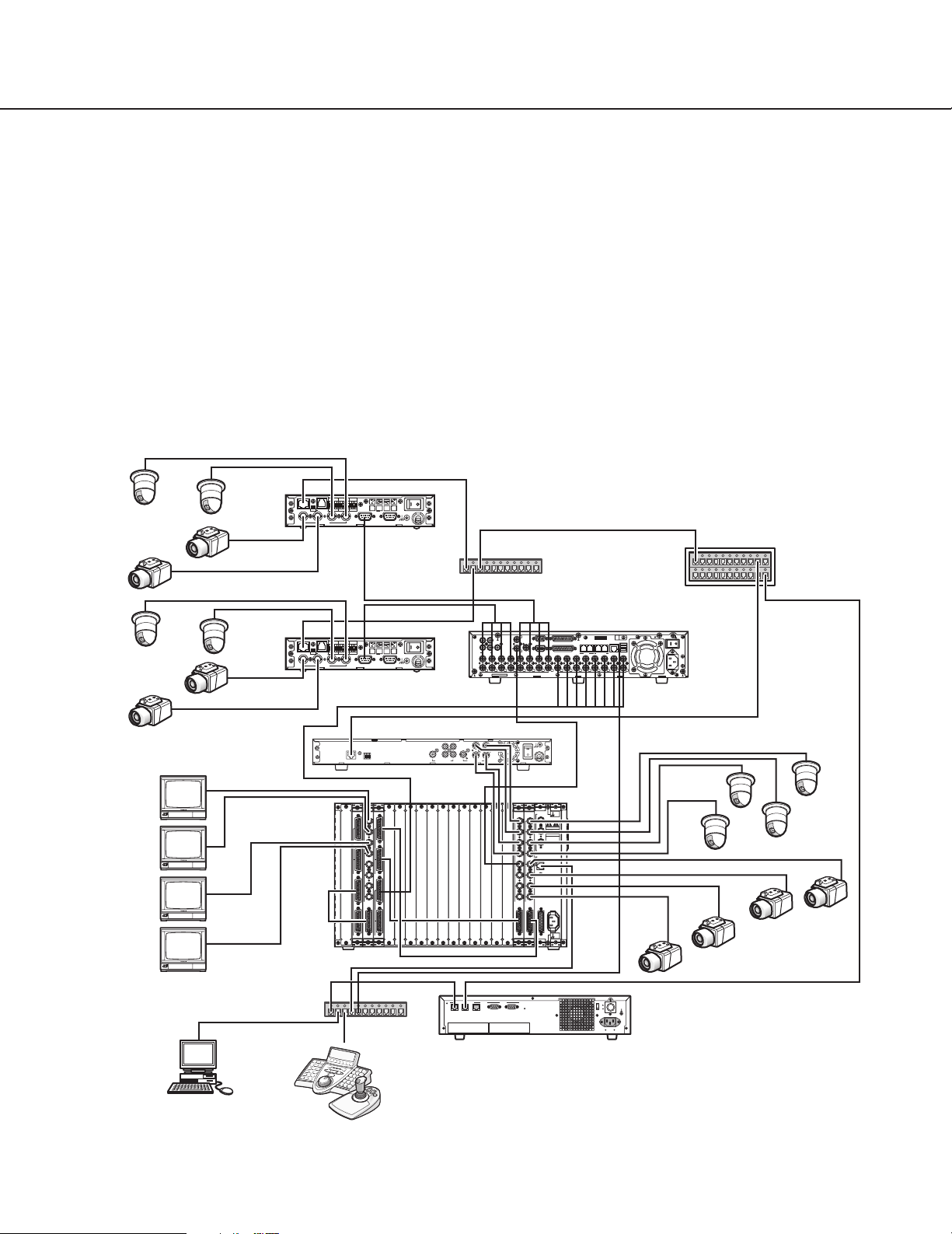
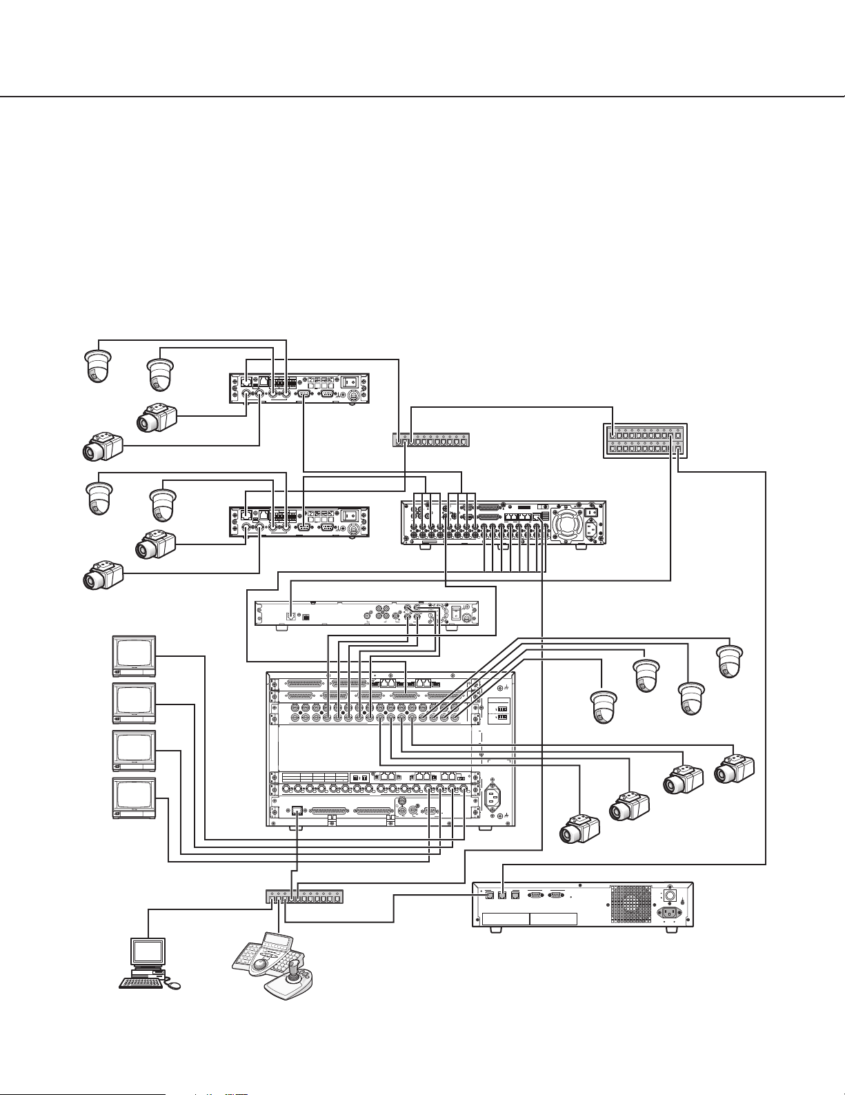
■ Single System Domain with Both GX and SX850 Switch Node
The following system contains one GX switch node and one SX850 switch node. The GX switch node consists of
two WJ-GXE900 encoders and one WJ-GXD900 decoder. The SX850 switch node contains a WJ-SX850 matrix
frame box with WJ-PB85X08 (MXCONT), WJ-PB85C16, WJ-PB85M16(MXSW), and WJ-PB85T08(MXOSD) boards.
There are four video links from WJ-GXD900 decoder to WJ-PB85C16 video inputs. The system also has WV-CU950
controllers for system or local operators, and a PC station with WJ-ASC960 Admin Console. The system’s WJMPU955A CPU must have the WJ-ASC960 upgrade software installed in order to perform all of the system functions. The sample Local database – 01=hybrid850.adm-and sys.ini file – 01A=sys.ini-for Administration Console are
provided on the CD-ROM. The sample Global database - #=hybrid850.gdm - for Admin is provided on the CD-ROM.
Also refer to Appendix 1.
Encoder 1
Cam9
Cam 13
Cam10
Cam11
Cam12
Cam14
Cam15
Cam16
WJ-GXD900
192.168.3.11
ON OFF
100BASE-TX RS-485
TERM
4
ON OFF
TERM
100BASE-TX RS-485
4
ALARM IN
TRIGGER OUT
RESET
+
–
4321G4321GGV
G
1
23
WJ-GXE900
192.168.1.10
ALARM IN
TRIGGER OUT
RESET
+
–
4321G4321GGV
G
1
23
WJ-GXE900
192.168.1.11
192.168.3.11
1000BASE-T
RESET
100BASE-TX
V+–G
POWER
ON OFF
AUDIO INVIDEO OUTVIDEO IN
GND
SIGNAL
Encoder 2
POWER
ON OFF
AUDIO INVIDEO OUTVIDEO IN
GND
SIGNAL
L2SW
Switching HUB
192.168.1.1
192.168.3.1
L3SW
192.168.200.1
Digital Disk Recorder 1
1
3
1
SERIAL
CASCADE
OUT
4 2
2
AUDIO IN AUDIO OUT
MONITOR OUT CASCADE IN
16
IN
OUT
16
MONITOR (VGA) ALARM/CONTROL
151414
13121211111010998877665544332211
13
15
18
MODE
ALARM
1
2
DATA
VIDEO
SIGNAL GND
COPY 1
EXT STORAGE10/100BASE-TRS485(CAMERA)
POWER
AC IN
WJ-HD300A Series
172.18.0.60
Decoder 1
1
2
2
QUAD
MIX
314
4
VIDEO OUTAUDIO OUT
ON
SIGNAL GND
3
OFF
POWER
Mon1
Mon2
Mon3
Mon4
PC with WJ-ASC960
Admin Console
OUTPUT
OSD
1
1
2
3
4
2
5
VIDEO IN
6
7
1
8
MONITOR OUT
2
VIDEO IN
VIDEO OUT
WJ-SX850
Switching HUB
System Controller
(Ethernet)
INPUT
1
2
VIDEO IN
1
2
VIDEO OUT
172.18.0.1
SIGNAL
THRU
CAMERA
VS / VD
GND
1
1
IN
CAUTION
DO NOT OPEN
RISK OF ELECTRIC SHOCK.
2
2
OUT
ATTENTION
NE PAS OUVRIR
RISQUE DE CHOCS
ELECTROUES
3
3
VD OUT
4
4
ETHERNET
5
5
6
6
7
7
8
8
IN/OUT
CAMERA IN
AC IN
SIGNAL
VIDEO OUT
GND
IN/OUT
RS-232C
192.168.200.200
10BASE-T/100BASE-TX
SERIAL
21OTHERSYSTEM
SYSTEM
DEVICE
CONTROLLER
CPU
POWER
ON
OFF
AC IN
SIGNAL GND
WJ-MPU955A (Equipped with WJ-ASC960)
Cam3
Cam8
Cam7
Cam4
Cam6
Cam1
Cam2
Cam5
Page 12

12
● Encoder WJ-GXE900 Setup
• Refer to WJ-GXE900 Operational Manual to set following configuration through the Web browser.
Encoder # Operation Mode IP Address Subnet Mask Default Gateway DNS Rotary Switch
1 Main CPU mode 192.168.1.10 255.255.255.0 192.168.1.1 0.0.0.0 0-0-1
2 Main CPU mode 192.168.1.11 255.255.255.0 192.168.1.1 0.0.0.0 0-0-2
● Decoder WJ-GXD900 Setup
• Refer to WJ-GXD900 Operational Manual to set following configuration through the Web browser.
Decoder # Operation Mode IP Address Subnet Mask Default Gateway DNS Rotary Switch
1 Main CPU mode 192.168.3.11 255.255.255.0 192.168.3.1 0.0.0.0 0-1-0
Note: The rotary dip-switch valued should not be same as Encoder’s one.
● L3SW Setup
• Set the following IP Address to each port.
Port # IP Address Connection
1 192.168.1.1 Encoder #1,2
2 192.168.3.1 Decoder #1
3 192.168.200.1 MPU955A
• Valid the IGMP V2 due to support Multicast messages.
● Card Cage WJ-SX850 Setup
• Refer to WJ-SX850 Operational Manual to set following configuration.
Slot # Board name/model # Rotary Switch Qty
– LCPU 0-2-0 Included
1 WJ-PB85X08 0-0 1
2 WJ-PB85Y08 – 1
15 WJ-PB85C16 0-0 1
16 WJ-PB85T08 0-0 1
17 WJ-PB85M16 0-0 1
– WJ-CA85L05(Multiple Video cable) – 3
● Digital Disk Recorder HD300A Series Setup
Digital Disk Recorder# Line Speed HTTP Port Number DHCP IP Address
1 AUTO 00080 OFF 172.018.000.060
Subnet Mask Gateway Unit Address (System) Unit Address (Controller)
255.255.000.000 000.000.000.000 001 001
Page 13
13
■ Single System Domain with Both GX and SX650 Switch Node
The following system contains one GX switch node and one SX650 switch node. GX switch node consists of two
WJ-GXE900 encoders and one WJ-GXD900 decoder. SX650 switch node contains a WJ-SX650 matrix switcher
input, output and a WJ-PB65E01 network board. There are four video links from WJ-GXD900 decoder to WJ-SX650
input board. The system also has WV-CU950 controllers for system or local operators, and a PC station with WJASC960 Admin Console. The system’s WJ-MPU955A CPU must have the WJ-ASC960 upgrade software installed in
order to perform all of the system functions. The sample Local database – 01=hybrid650.adm-and sys.ini file –
01A=sys.ini-for Administration Console are provided on the CD-ROM. The sample Global database #=hybrid650.gdm - for Admin is provided on the CD-ROM. Also refer to Appendix 3.
Cam9
Cam 13
Mon1
Mon2
Mon3
Mon4
Cam12
Cam16
Cam10
Cam11
Cam14
Cam15
WJ-GXD900
192.168.3.11
WJ-SX650
ON OFF
TERM
100BASE-TX RS-485
4
ON OFF
100BASE-TX RS-485
TERM
4
RESET
+
–
G
Encoder 1
POWER
ON OFF
AUDIO INVIDEO OUTVIDEO IN
GND
SIGNAL
TRIGGER OUT
4321G4321GGV
23
ALARM IN
1
WJ-GXE900
192.168.1.10
Encoder 2
ALARM IN
TRIGGER OUT
4321G4321GGV
23
RESET
+
–
1
POWER
G
ON OFF
SIGNAL
AUDIO INVIDEO OUTVIDEO IN
GND
WJ-GXE900
192.168.1.11
192.168.3.11
1000BASE-T
RESET
100BASE-TX
V+–G
EXTENSION 3 IN
VIDEO OUT 3
VIDEO OUT 4
32 31 30 29 28 27 26 25 24 23 22 21 20 19 18 17
16 15 14 13 12 11 10 9
DATA 4
DATA 3
DATA 2
HDR4/TMNL8
HDR3/TMNL7
10/100 BASE-T
HDR2/TMNL4
HDR1/TMNL3
ALARM OUT 2
TMNL6
TMNL2
Video Output Board 2
Video Output Board 1
WJ-SX850
DATA 1
TMNL5
TMNL1/PS DATA
EXTENSION 2 IN
TERM.ON
TERM.OFF
ON
MODE
MODE
2
MIX
4
RS485 (CAMERA) RS485 (CAMERA)
MODE
VIDEO OUT 2
CAMERA IN
910111213141516
MONITOR OUT
ALARM OUT 1
Switching HUB
L2SW
Switching HUB
1
3
1
4 2
AUDIO IN AUDIO OUT
16
IN
OUT
16
1
2
QUAD
314
3
4
VIDEO OUTAUDIO OUT
21
3
MODE MODE MODE
VIDEO OUT 1
87654321
DATA
DATA
VS IN
VS OUT
VS OUT
(THRU)
172.18.0.1
SERIAL
2
ON
OFF
POWER
MONITOR (VGA) ALARM/CONTROL
SIGNAL GND
IN C-3
IN X-2
IN X-1
OFF
ON
OUT X-3
IN
TERM.
12345678
OUT X-2
NETWORK OUT X-1
ALARM
VIDEO
C
SIGNAL GND
3
2
RS485(CAMERA) SET UP
ON
4-Line
MODE
ON
4-Line
1
MODE
B
3
2
1
A
AC IN
3
2
SIGNAL GND
1
10BASE-T/100BASE-TX
SYSTEM
DEVICE
CONTROLLER
CASCADE
OUT
MONITOR OUT CASCADE IN
151414
13121211111010998877665544332211
13
15
Decoder 1
ALARM IN
1234
MODEMODEMODEMODE
EXTENSION 1
OUT
Video Output Board 1 Only
SERIAL
192.168.1.1
Digital Disk Recorder 1
18
MODE
2
DATA
1
SIGNAL GND
COPY 1
EXT STORAGE10/100BASE-TRS485(CAMERA)
WJ-HD300A Series
172.18.0.60
Cam8
192.168.200.200
SERIAL
21OTHERSYSTEM
192.168.3.1
POWER
AC IN
Cam1
Cam2
Cam7
L3SW
Cam6
POWER
ON
OFF
AC IN
Cam3
SIGNAL GND
192.168.200.1
Cam4
Cam5
PC with WJ-ASC960
Admin Console
WJ-MPU955A (Equipped with WJ-ASC960)
System Controller
(Ethernet)
Page 14

14
● Encoder WJ-GXE900 Setup
Same as System850 description
● Decoder WJ-GXD900 Setup
Same as System850 description
● L3SW Setup
Same as System850 description
● WJ-SX650 Setup
Slot # Board name Rotary Switch/Mode Qty
C Video Input Board 0 1
B
A Video Output Board with Network Board Output Board (1) 1
● Digital Disk Recorder HD300A Series Setup
Same as System850 description
Page 15
15
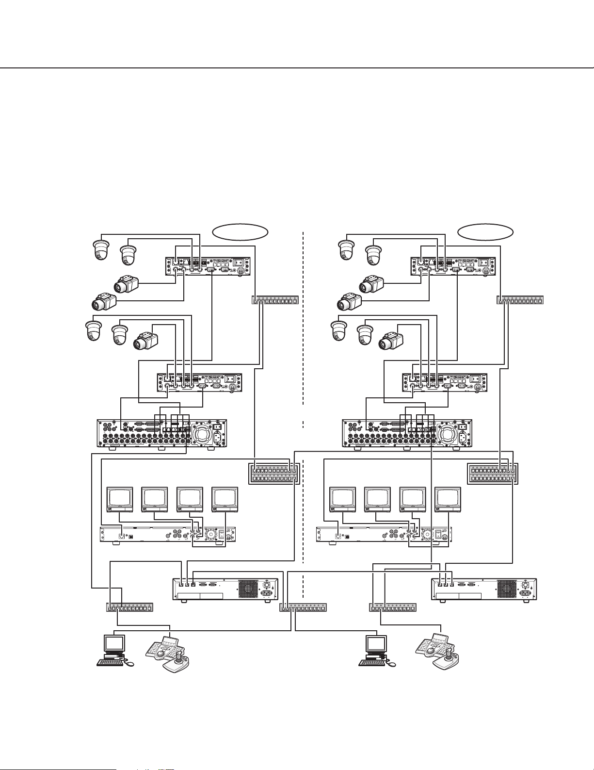
■ Multiple System Domains with Single GX Switch Node
The following system includes two system domains. Each system domain has its own GX switch node. The system
domain has two WJ-GXE900 encoders and one WJ-GXD900 decoder. It contains a domain WJ-MPU955A CPU with
the WJ-ASC960 upgrade software installed. Within the domain, a PC with WJ-ASC960 Admin Console software
installed is required to configure resources and operations within the domain. The two system domains can work
independently as standalone systems. The sample Local database – 01=multi_1.adm, 02=multi_2.adm -and sys.ini
file – 01A=sys.ini, 02A=sys.ini -for Administration Console are provided on the CD-ROM. The sample Global database - #=multi.gdm - for Admin is provided on the CD-ROM. Also refer to Appendix 2.
Cam1-1
Cam1-5
Digital Disk
Recorder 1-1
WJ-HD300A
Series
172.18.0.60
Domain 1
Encoder 1-1
ALARM IN
TRIGGER OUT
Cam1-2
Cam1-3
Cam1-4
ON OFF
100BASE-TX RS-485
TERM
4
23
4321G4321GGV
1
POWER
ON OFF
SIGNAL
GND
WJ-GXE900
192.168.1.10
Cam2-1
+
–
G
AUDIO INVIDEO OUTVIDEO IN
Cam2-2
Cam2-4
L2SW
Switching
Cam2-3
RESET
HUB
192.168.1.1
Cam1-6
Cam1-7
100BASE-TX RS-485
4
ON OFF
4321G4321GGV
TERM
1
23
POWER
+
–
G
ON OFF
SIGNAL
AUDIO INVIDEO OUTVIDEO IN
GND
Encoder 1-2
ALARM IN
TRIGGER OUT
RESET
Cam2-5
Cam2-6
Cam2-7
100BASE-TX RS-485
4
WJ-GXE900
1
3
1
SERIAL
CASCADE
OUT
4 2
2
AUDIO IN AUDIO OUT
MONITOR OUT CASCADE IN
MONITOR (VGA) ALARM/CONTROL
16
151414
13121211111010998877665544332211
IN
OUT
15
16
13
192.168.1.11
18
MODE
ALARM
1
2
DATA
VIDEO
SIGNAL GND
COPY 1
EXT STORAGE10/100BASE-TRS485(CAMERA)
POWER
AC IN
Digital Disk Recorder 2-1
WJ-HD300A Series
172.18.0.60
192.168.2.1
192.168.5.1
1
3
1
SERIAL
CASCADE
OUT
4 2
2
AUDIO IN AUDIO OUT
MONITOR OUT CASCADE IN
MONITOR (VGA) ALARM/CONTROL
16
151414
13121211111010998877665544332211
IN
OUT
15
16
13
ALARM
DATA
VIDEO
L3SW-1
Mon1-1 Mon1-2 Mon1-3 Mon1-4 Mon2-1 Mon2-2 Mon2-3 Mon2-4
192.168.200.1
ON OFF
100BASE-TX RS-485
TERM
4
TRIGGER OUT
ON OFF
4321G4321GGV
TERM
23
18
MODE
1
2
ALARM IN
TRIGGER OUT
4321G4321GGV
1
23
ALARM IN
RESET
+
–
G
1
COPY 1
EXT STORAGE10/100BASE-TRS485(CAMERA)
L3SW-2
Domain 2
Encoder 2-1
RESET
POWER
+
–
G
ON OFF
AUDIO INVIDEO OUTVIDEO IN
GND
SIGNAL
L2SW
Encoder 2-2
POWER
ON OFF
SIGNAL
AUDIO INVIDEO OUTVIDEO IN
GND
WJ-GXE900
192.168.3.11
SIGNAL GND
POWER
AC IN
192.168.4.1
192.168.201.1
WJ-GXE900
192.168.3.10
Switching
HUB
192.168.3.1
192.168.5.2
1000BASE-T
RESET
100BASE-TX
V+–G
WJ-GXD900
192.168.2.10
Switching HUB
PC with WJ-ASC960
Admin Console
2
MIX
172.18.0.1
System Controller
(Ethernet)
1
2
QUAD
314
ON
SIGNAL GND
3
4
VIDEO OUTAUDIO OUT
Decoder 1-1 Decoder 2-1
OFF
POWER
192.168.200.200
172.16.192.1
10BASE-T/100BASE-TX
SERIAL
21OTHERSYSTEM
SYSTEM
DEVICE
CONTROLLER
CPU-1
WJ-MPU955A
Equipped with WJ-ASC960
POWER
ON
OFF
AC IN
SIGNAL GND
WJ-GXD900
192.168.4.10
172.16.192.2
Switching HUB
1000BASE-T
RESET
100BASE-TX
V+–G
2
MIX
172.18.0.1
Switching HUB
PC with WJ-ASC960
Admin Console
1
2
QUAD
314
ON
3
4
OFF
VIDEO OUTAUDIO OUT
POWER
SYSTEM
CONTROLLER
System Controller
(Ethernet)
SIGNAL GND
192.168.201.200
10BASE-T/100BASE-TX
SERIAL
21OTHERSYSTEM
DEVICE
WJ-MPU955A
POWER
ON
OFF
AC IN
CPU-2
Equipped with WJ-ASC960
SIGNAL GND
Page 16

16
● Encoder WJ-GXE900 Setup
• Refer to WJ-GXE900 Operational Manual to set following configuration through the Web browser.
Encoder # Operation Mode IP Address Subnet Mask Default Gateway DNS Rotary Switch
1-1 Main CPU mode 192.168.1.10 255.255.255.0 192.168.1.1 0.0.0.0 0-0-1
1-2 Main CPU mode 192.168.1.11 255.255.255.0 192.168.1.1 0.0.0.0 0-0-2
2-1 Main CPU mode 192.168.3.10 255.255.255.0 192.168.3.1 0.0.0.0 0-0-3
2-2 Main CPU mode 192.168.3.11 255.255.255.0 192.168.3.1 0.0.0.0 0-0-4
Encoder # MULTICAST IP ADDRESS FOR SETUP
in System Setup page
1-1 239.192.255.2(default)
1-2 239.192.255.2(default)
2-1 239.192.255.3
2-2 239.192.255.3
● Decoder WJ-GXD900 Setup
• Refer to WJ-GXD900 Operational Manual to set following configuration through the Web browser.
Decoder # Operation Mode IP Address Subnet Mask Default Gateway DNS Rotary Switch
1-1 Main CPU mode 192.168.2.10 255.255.255.0 192.168.2.1 0.0.0.0 0-1-0
2-1 Main CPU mode 192.168.4.10 255.255.255.0 192.168.4.1 0.0.0.0 0-1-1
Decoder # MULTICAST IP ADDRESS FOR SETUP
in System Setup page
1-1 239.192.255.2(default)
2-1 239.192.255.3
Note: The rotary dip-switch valued should not be same as Encoder’s one.
● L3SW-1 Setup
• Set the following IP Address to each port.
Port # IP Address Connection
1 192.168.1.1 Encoder #1-1,1-2
2 192.168.2.1 Decoder #1-1
3 192.168.5.1 Link to L3SW-2
4 192.168.200.1 CPU-1
• Valid the IGMP V2 due to support Multicast messages.
Page 17

17
● L3SW-2 Setup
• Set the following IP Address to each port.
Port # IP Address Connection
1 192.168.3.1 Encoder #2-1, 2-2
2 192.168.4.1 Decoder #2-1
3 192.168.5.2 Link to L3SW-1
4 192.168.201.1 CPU-2
• Valid the IGMP V2 due to support Multicast messages.
● Digital Disk Recorder HD300A Series Setup
Digital Disk Recorder# Line Speed HTTP Port Number DHCP IP Address
1-1 AUTO 00080 OFF 172.018.000.060
2-1 AUTO 00080 OFF 172.018.000.060
Subnet Mask Gateway Unit Address (System) Unit Address (Controller)
255.255.000.000 000.000.000.000 001 001
255.255.000.000 000.000.000.000 001 001
Page 18
18
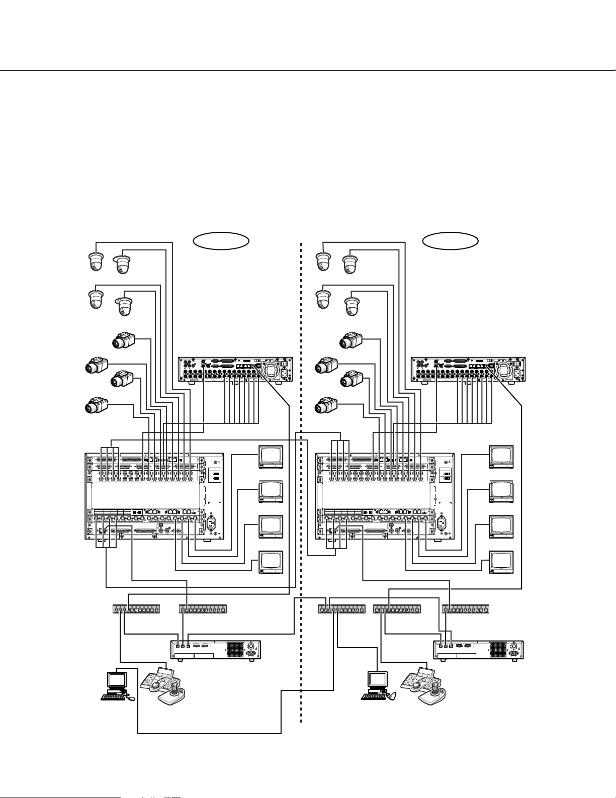
■ Multiple System Domains with Single SX650 Switch Node
The following system includes two system domains. Each system domain has its own SX650 switch node. The system domain has two WJ-SX650 matrix switchers. It contains a domain WJ-MPU955A CPU with the WJ-ASC960
upgrade software installed. Within the domain, a PC with WJ-ASC960 Admin Console software installed is required
to configure resources and operations within the domain. The two system domains can work independently as
standalone systems. The sample Local database – 01=multi650_1.adm, 02=multi650_2.adm -and sys.ini file –
01A=sys.ini, 02A=sys.ini -for Administration Console are provided on the CD-ROM. The sample Global database #=multi650.gdm - for Admin is provided on the CD-ROM. Also refer to Appendix 4.
Domain 1 Domain 2
Cam1-1
Cam1-3
Cam1-2
Cam1-4
Cam1-5
Cam1-6
Cam1-7
Cam1-8
EXTENSION 2 IN
EXTENSION 3 IN
VIDEO OUT 3
VIDEO OUT 4
32 31 30 29 28 27 26 25 24 23 22 21 20 19 18 17
16 15 14 13 12 11 10 9
DATA 4
DATA 3
DATA 2
Video Output Board 2
Video Output Board 1
DATA 1
HDR4/TMNL8
HDR3/TMNL7
TMNL6
TMNL5
HDR2/TMNL4
HDR1/TMNL3
TMNL2
TMNL1/PS DATA
10/100 BASE-T
ALARM OUT 2
21
4
3
RS485 (CAMERA) RS485 (CAMERA)
MODE
MODE MODE MODE
VIDEO OUT 1
VIDEO OUT 2
87654321
CAMERA IN
TERM.ON
TERM.OFF
ON
MODE
MODE
910111213141516
MONITOR OUT
ALARM OUT 1
1234
MODEMODEMODEMODE
DATA
DATA
VS IN
VS OUT
SERIAL
VS OUT
(THRU)
WJ-HD300A Series
1
3
1
SERIAL ALARM
CASCADE
OUT
4 2
2
AUDIO IN AUDIO OUT
MONITOR OUT CASCADE IN
MONITOR (VGA) ALARM/CONTROL
16
13
IN
OUT
16
1515141413
12121111101099887766554433221
VIDEO
Cam2-1
Cam2-3
MODE
1182
DATA
SIGNAL GND
COPY 1
POWER
EXT STORAGE10/100BASE-TRS485(CAMERA)
1
AC IN
Cam2-6
Cam2-2
Cam2-4
Cam2-5
3
1
CASCADE
OUT
4 2
AUDIO IN AUDIO OUT
16
IN
OUT
16
1515141413
Cam2-7
Cam2-8
WJ-SX650 WJ-SX650
C
SIGNAL GND
ALARM IN
EXTENSION 1
OUT
Video Output Board 1 Only
3
IN C-3
2
IN X-2
RS485(CAMERA) SET UP
ON
4-Line
MODE
ON
4-Line
1
MODE
IN X-1
B
3
2
1
A
OFF
ON
AC IN
3
OUT X-3
IN
TERM.
2
12345678
OUT X-2
SIGNAL GND
1
NETWORK OUT X-1
Mon1
Mon2
Video Output Board 2
Video Output Board 1
EXTENSION 2 IN
EXTENSION 3 IN
VIDEO OUT 3
VIDEO OUT 4
32 31 30 29 28 27 26 25 24 23 22 21 20 19 18 17
16 15 14 13 12 11 10 9
DATA 4
DATA 3
DATA 2
DATA 1
TERM.OFF
HDR4/TMNL8
HDR3/TMNL7
TMNL6
TMNL5
HDR2/TMNL4
HDR1/TMNL3
TMNL2
TMNL1/PS DATA
MODE
10/100 BASE-T
ALARM OUT 2
21
4
3
RS485 (CAMERA) RS485 (CAMERA)
MODE
MODE MODE MODE
ALARM IN
VIDEO OUT 1
VIDEO OUT 2
87654321
CAMERA IN
TERM.ON
ON
MODE
910111213141516
MONITOR OUT
ALARM OUT 1
1234
MODEMODEMODEMODE
EXTENSION 1
OUT
DATA
DATA
VS IN
Video Output Board 1 Only
VS OUT
SERIAL
VS OUT
(THRU)
IN
OFF
TERM.
NETWORK OUT X-1
IN C-3
IN X-2
IN X-1
ON
OUT X-3
12345678
OUT X-2
Mon3
WJ-HD300A Series
1
SERIAL ALARM
2
MONITOR OUT CASCADE IN
MONITOR (VGA) ALARM/CONTROL
13
12121111101099887766554433221
C
SIGNAL GND
3
2
RS485(CAMERA) SET UP
ON
4-Line
MODE
ON
4-Line
1
MODE
B
3
2
1
A
AC IN
3
2
SIGNAL GND
1
MODE
1182
EXT STORAGE10/100BASE-TRS485(CAMERA)
DATA
VIDEO
COPY 1
1
Mon1
Mon2
Mon3
SIGNAL GND
POWER
AC IN
PC with WJ-ASC960
Admin Console
Switching HUB
172.18.0.1
System Controller
(Ethernet)
Switching HUB
192.168.200.200
10BASE-T/100BASE-TX
SERIAL
21OTHERSYSTEM
SYSTEM
DEVICE
CONTROLLER
WJ-MPU955A
(Equipped with WJ-ASC960)
POWER
ON
OFF
Mon4
172.16.192.1
SIGNAL GND
AC IN
172.16.192.2
Switching
Switching HUB
HUB
PC with WJ-ASC960
Admin Console
172.18.0.1
System Controller
(Ethernet)
Mon4
Switching HUB
192.168.200.200
10BASE-T/100BASE-TX
SERIAL
21OTHERSYSTEM
SYSTEM
DEVICE
CONTROLLER
WJ-MPU955A
(Equipped with WJ-ASC960)
POWER
ON
OFF
AC IN
SIGNAL GND
Page 19

19
● WJ-SX650 Setup
Slot # Board name Rotary Switch/Mode Qty
C Video Input Board 0 1
B
A Video Output Board with Network Board Output Board (1) 1
● Digital Disk Recorder HD300A Series Setup
Same as Single System Domain with Both GX and SX850 Switch Node on page 12
Page 20

20
System Setup
■ Define a System Domain
● Number of System Domains
By definition, each system domain must have a WJ-MPU955A CPU. If it is a redundant system, it must have two
WJ-MPU955A CPUs. The system can consist of up to 64 system domains.
● Domain and Unit ID Assignments
For each CPU, you must assign a Unit ID. Once a Unit ID is assigned, the system will refer to its Domain ID equal to
this Unit ID.
● Enter Unit ID in the WJ-ASC960 Admin Console
In the WJ-ASC960 Admin Console main screen, select CPU Units on the Domain menu. The CPU System
Configuration screen will be activated.
Then, enter the Unit(s) information into the fields provided. In the following
table, we used the example on page 15 to show what information you would need to enter.
Unit ID Main IPA [A] Backup IPA [B] Unit Name Size
1 172.16.192.1 – Domain 1 Enhanced
2 172.16.192.2 – Domain 2 Enhanced
● Enter Unit ID in the System Configuration File
In each WJ-MPU955A CPU, there is a system configuration file named SYS.INI. You can view and edit the file
through WJ-ASC960 Admin Console. For each new system domain that is set up, you need to enter the correct ID in
the [UNIT] section of the SYS.INI file. The following is the text from the SYS.INI file's [UNIT] section.
[UNIT]
***{ The unit ID should be the same as the one defined in }
***{ the Global Admin database for this unit. }
***{ For single-unit systems, use ID=1. (ID=0 is invalid) }
ID=1
Page 21

21
■ Define a Video Switch Node
● GX Switch Node
A GX switch node consists of one or more video decoder devices (WJ-GXD900) and video encoder devices (WJGXE900). A GX switch node can be in a single system domain or across multiple system domains. Currently, the
system only supports one GX switch node, and the node ID is always set to zero by the system software.
● GX Switch Node and its Domain
For each GX switch node, there can be many encoder and decoder devices. In the case of a single domain system,
such as the system on page 11, all the encoder and decoder devices will be assigned to that domain.
The GX node can split into multiple system domains. In the case of a multiple domain system, the system designer
has to decide which domain the encoder and decoder devices should belong to.
For the system on page 15, we decided that encoder 1-1, encoder 1-2, and decoder 1-1 are in domain 1, while
encoder 2-1, encoder 2-2, and decoder 2-1 are in domain 2.
In general, we recommend that you should search for a nearby CPU and assign encoder or decoder devices to the
same domain ID of the CPU.
● Enter Encoders and Decoders in the WJ-ASC960 Admin Console
After deciding the domain ID for each encoder and decoder, the next step is to enter the encoder and decoder
device information in the WJ-ASC960 Admin Console for the domain.
In the WJ-ASC960 Admin Console GX DEVICES screen, we need to configure the devices here.
Since these devices are part of the digital node, select GX from the Switch Nodes command on the Domain menu.
Following are the sample data for encoder and decoder devices:
ID I/F IPA EA Encoder
Input
Ports
Decoder
Output
Ports
GXDIN
Input
Ports
2 0 192.168.1.10 00:00:00:00:00:00 9 - 12
–
9 - 12
Address [SW1]GXOSD
Output
Ports
ABC
001
3 0 192.168.1.11 00:00:00:00:00:00 13 - 16
– 13 - 16
002
4 0 192.168.3.1 00:00:00:00:00:00 – 1 - 4
–
GXDOUT
Output
Ports
9 - 12
13 - 16
–
010
–
–
1 - 4
For detail configuration information, users should refer to WJ-MPU955A Operating Instructions.
● SX850 Switch Node
SX850 switch node consists of one or more WJ-SX850 cages with WJ-PB85C16/WJ-PB85M16 (MXSW) and other
matrix controllers (WJ-SX850). SX850 switch node can only be located within a system domain, and cannot cross
over multiple domains. Currently, the system only supports up to one SX850 switch node in a single system domain,
and the node ID is always set to its domain ID by the system software.
Page 22

ID
22
ID
● SX850 Switch Node and its Domain
For each SX850 switch node, there can be many matrix switch, matrix controller, and matrix OSD devices. In case of
a single domain system, such as the system on page 11, all the matrix controller devices will be assigned to that
domain.
In case of a multiple domain system, the system designer has to decide which domain the matrix controller devices
should belong to.
● Enter SX850 FRAMES in the WJ-ASC960 Admin Console
After deciding the domain ID for each SX850 matrix controller, the next step is to enter the information in the WJASC960 Admin Console for the domain.
In the WJ-ASC960 Admin Console, SX850 FRAMES screen, we need to configure the devices. Since these devices
are part of the SX850 node, select SX850 from the Switch Nodes command on the Domain menu. Following are
the sample data for matrix controller devices:
I/F IPA Boot MXCONT MXOSD MXALM
1 1 172.18.0.100 15010426.sr 1-128
1-128
–
MXSW
Input Output
1-256 1-32
LCPU Address
SW12 SW10 SW9
020
● SX650 Switch Node
SX650 switch node consists of one more WJ-SX650 matrix switcher with WJ-PB65E01 network board. SX650
switch node can only be located within a system domain, and cannot cross over multiple domains. Currently, the
system only supports up to one SX650 switch node in a single system domain, and node ID is always set to its
domain ID by the system software.
● SX650 Switch Node and its Domain
In case of a single domain system, all the WJ-SX650 matrix switcher with WJ-PB65E01 network board will be
assigned to that domain.
In case of a multiple domain system, the system designer has to decide which domain all the WJ-SX650 matrix
switcher with WJ-PB65E01 network board should belong to.
● Enter SX650 SUBNODES in the WJ-ASC960 Admin Console
After deciding the domain ID for each WJ-SX650 matrix switcher, the next step is to enter the information in the WJASC960 Admin Console for the domain.
In the WJ-ASC960 Admin Console, SX650 SUBNODES screen, we need to configure the devices. Since these
devices are part of the SX650 node, select SX650 from the Switch Nodes command on the Domain menu.
Following are the sample data for WJ-SX650 matrix switcher.
EAIF IPA BRIDGE CONTROL OSD
SWITCH
Input Output
ALARM
Address [MODE]
5678
1 1 172.18.0.100 – 1 - 256 1 - 32 1 - 256 1 - 32 – OFF OFF ON OFF 00.00.00.00.00.00
Page 23

23
■ How to Identify a Video Switch Link
● Links between an SX650/SX850 Node and a GX Node
In order to pass video from one switch node to another, video links are required. Page 11 gave an example of a system with video links. In general, you can find video links in the following conditions:
• From a video decoder device to an SX650/SX850 matrix switch input
• From an SX650/SX850 matrix switch output to a video encoder device
The above video links can connect two video switch nodes within the same system domain or different system
domains.
● Links between two SX650/SX850 Switch Nodes
In general, you can find video links from a matrix switch output to a matrix switch input. These links must cross two
different system domains.
● Enter Video Links in the WJ-ASC960 Admin Console (Global database)
In the WJ-ASC960 Admin Console main screen, select Routing on the Domain menu. The LINK screen will be activated. Then, enter the video link(s) information into the fields provided. In the following table, we used the example
on page 11 to show what information you would need to enter.
In the above video link table, users are able to enable or disable a video link. When disabled, the system will not use
that link in its video routing operation.
Also in the above video link table, the destination unit ID and source unit ID are the same. They also can be different
in a multiple domain system.
In the example on page 15, there is no video link in the GX system, and users can skip this configuration.
■ Define System Operators
● System Operators
System operators are also called global operators or system users. In order to seize a system resource, such as a
camera in a foreign domain, the system requires a global operator. When a global operator logs into a system controller, it becomes a global controller.
Link ID1Enable
✓
1
Video Source
Unit ID Switch
Video Destination Navigation Cost
PortUnit ID
GX 1 1 SX850 9 1
2
✓
1 GX 2 1 SX850 10 1
3
4
✓
1 GX 4 1 SX850 12 1
✓
1 GX 3 1 SX850 11 1
Switch Port
Page 24

24
The global operator is subject to unit partitioning restrictions, where within their domain, she/he will act like a local
super user.
● Enter Global Operators in the WJ-ASC960 Admin Console (Global Database)
In the WJ-ASC960 Admin Console main screen, select Operators → Records on the Components menu. The
OPERATORS screen will be activated. Then, enter the operator(s) information into the fields provided. For global
operator(s), you can select one of the four global class levels.
User ID Password Priority Timeout Name Class
500 500 2 00:00:00 Global Operator 1 20: Global Level 0
100 123 10 00:00:00 Global Operator 2 20: Global Level 0
● Enter Operator to Unit Partitioning in the WJ-ASC960 Admin Console
In the WJ-ASC960 Admin Console main screen, select Operator → Records on the Components menu. The
OPERATORS screen will be activated. Then, select the Unit tab and check the partitioning you want to apply to a
global operator.
■ Additional GX Switch Node Setup
● Setup Multicast IP Address for Encoder and Decoder Devices
The following steps are required to set up the multicast IP address for each system domain Encoder and Decoder.
Using the WJ-ASC960 Global Admin tool PC, launch Internet Explorer.
1) http://xxx.xxx.xxx.xxx
Enter the IP address (such as xxx.xxx.xxx.xxx) of the WJ-GXE900 or WJ-GXD900 in the address box of the Web
browser and press the ENTER key. The top page will be displayed.
2) Click the ‘SYSTEM’ button in the left column on the top page.
The authentication dialog window will be displayed. Enter a user name whose access level is 1 (ADMINISTRATOR) and a password, and click the [OK] button. When authenticated, SYSTEM setup page will be displayed
3) Set the IP address into MULTICAST IP ADDRESS FOR SETUP by following table.
Unit ID MULTICAST IP ADDRESS
1 (Default) 239.192.255.2 (Default)
2 239.192.255.3
3 239.192.255.4
4 239.192.255.5
5 239.192.255.6
62 239.192.255.63
63 239.192.255.64
64 239.192.255.65
4) All WJ-GXE900 and WJ-GXD900s are needed to set up the same MULTICAST IP ADDRESS FOR SETUP.
Page 25

25
■ Upgrade MPU955A CPU to ASC960
To upgrade a standalone WJ-MPU955A system to a distributed WJ-ASC960 system, please refer to MPEG2
Encoder WJ-GXE900, MPEG2 Decoder WJ-GXD900 Operating Instructions. With this upgrade, you can create a
multiple domain system that forms a large scale system.
Page 26

26
Main Features
■ System Operator Functions
● Operator Log On and Off
Each system operator is assigned a user ID and password by a global system administrator. A user ID and password are required for any operators to log on to the system. System administrators can decide to automatically log
operators off if there is no activity for a pre-defined time period.
● Operator Priority
The global administrator can assign a priority to each operator. When two operators compete for system resources,
only the operator with the higher priority gets the resources.
■ Global Video Switch and Video Routing
This function allows operators to switch video from one video source to another, if the permission is granted. For
multiple operators competing for the same resource, it only allows the highest priority operator to perform this function. The next highest priority operator gains control when the highest priority operator releases the resource. Here is
a sample operation to switch video from local camera number 1 in domain 1, to another camera number 1 in domain
2, on a local monitor number 1.
1. Login to System Controller: Enter 500 for ID and enter 500 for password (Global Operator).
2. Select monitor 1: Enter 1 and press MONITOR key.
3. Select local camera 1: Enter 1 and press CAMERA key.
4. Select global camera 1(Unit2’s camera 1): Enter 200001 and press CAMERA key.
Note: Format: Unit (Domain) id (2) + Camera number (1). E.g. 200001 (Unit 2, Camera 1)
(Note that first entry digit must be non-zero, and must not exceed eight digits).
Note: Only Global Operator can access foreign domain resources.
Please note that first entry digit must be non-zero, and must not exceed 2 digits. Also, entry will overflow if the
domain ID entered is greater than 64.
Page 27

27
■ Global Video Camera Control and Operation
● Global Camera Seize
Operators must seize a camera in order to perform camera operations. After Global Video Switch and Video Routing
(refer to page 26), you can seize a camera 200001, which means a camera in domain 2 with a camera ID of 1.
● Camera Control
The system provides operators with camera control functions. The supported functions are: pan, tilt, zoom, focus,
and iris.
● Camera Operation
The system provides operators with the following camera operation functions:
• Camera menu control
• Camera preset call and programming
• Camera receiver control
■ Global Video Recorder Control and Operation
● Global Recorder Selection
Operators must seize a digital disk recorder in order to perform recorder operations. After Global Video Switch and
Video Routing (refer to page 26), you can seize a recorder 200001, which means a recorder in domain 2 with a
recorder ID of 1.
● Recorder Basic Operation
The system provides operators with the following video recorder functions:
• Recording
• Playback, pause, and stop
• Fast-forward and rewind playback at different speeds
• Video input channel selection
• Multiscreen segment switching
● Recorder Search Functions
The system provides operators with the following recorder search functions:
• Date-and-time search playback
• Recording event search (Thumbnail or list search)
• VMD search (Video motion detection search)
● Recorder Menu Functions
The system provides operators with the following recorder menu functions:
Page 28

28
• Recorder setup menu
• Disk selection menu
• A – B repeat playback menu
• Filter cancellation menu
● Recorder Instant Playback Operation
The system provides operators with the instant playback operation for a seized global camera.
■ Global Tour Sequences
● Local Monitor Seize
The system allows global operators to start and control a tour sequence from another system domain. Before tour
sequence operation, a local monitor must be seized. Here is the sample procedure to seize local monitor number 1
in domain 1:
1. Login to System Controller: Enter 500 for ID and enter 500 for password (Global Operator).
2. Select monitor 1: Enter 1 and press MONITOR key.
● Tour Sequence Operation
Tour sequence operations include start, stop, pause, run, next step, and previous step. Here is the sample to start a
tour sequence:
Run global tour sequence 1(Domain 2’s tour sequence 1):
Enter 20010001 and press TOURSEQ key.
Notes:
• Format: Domain id (2) + Area number (1) +Tour number (1). E.g. 20010001
• Only Global Operator can access foreign domain resources.
Please note that the first entry digit must be non-zero, and must not exceed 2 digits. Also, the entry will overflow if
the domain ID entered is greater than 64.
The WJ-ASC960 can execute 20 tour sequence steps per second. If the WJ-ASC960 is asked to perform more than
20 steps in a single second, it will automatically form 20-step groups, and alternate their execution over a period of
two or more seconds.
Page 29

29
■ Alarm Export to other Domains
● Alarm Export Function
This function allows administrators to assign an alarm export to another system domain.
● Assign Alarm Export in WJ-ASC960 Admin Console
In the WJ-ASC960 Admin main screen, select Components → Alarms → Records → Export tab. From there, you can
add, delete, and edit an alarm to be exported to multiple system domains (units). The alarm ID has the following format:
Domain (Unit) id (2) + Alarm id (1). E.g. 20001
In the above format, the domain ID has up to 2 digits and its range is from 1 … 64. The domain ID here is also called
alarm source domain, which means that the alarm originates from that domain.
● Setup an Exported Alarm in WJ-ASC960 Admin Console
After creating an alarm to be exported to a destination domain, an administrator must enter the alarm information
into the destination domain alarm database using its WJ-ASC960 Admin Console.
In the WJ-ASC960 Admin Console main menu, select Records from the Alarm command on the Components
menu. For alarm source, select the source type Global Alarm and ID to 20001 (in the above case).
You should also go to the alarm target screen and action screen to complete your normal alarm setup.
■ System Wide Log View
The system supports the following system logs:
• Operator log
• Alarm log
In the WJ-ASC960 Admin Console main screen select the Tools, Logs, and System links to view system wide user
logs and alarm logs.
Page 30

30
Check the video link direction in the “Routing
Configuration” screen of the global admin. Video links on
the decoder side should be the source node and matrix
side should be the destination side.
■ Video Switch Node-Related problems
No video switch between
monitors in analog node and
cameras in digital node
P. 23
Symptom
Reference pagePossible cause / Possible solution
Check whether the global operator subjects to the tour
sequence unit partitioning.
Check whether you enter a correct unit id for the globaltour sequence.
Check whether the global operator subjects to the camera unit partitioning.
Check whether you enter a correct unit id for the global
camera.
Check whether global database has been updated for
this operator.
Users typed correct password.
Troubleshooting
Before contacting technical support, please check the following symptoms and their possible causes and solutions. If
the solutions suggested do not solve the problem, or if the symptom is not listed below, contact your installer or
sales representative.
■ Global Operation-Related problems
Symptom
Reference pagePossible cause / Possible solution
Global Operator fails to login
Global Operator fails to
select a global camera
Global Operator fails to start
a global tour sequence
WJ-ASC960
Installation
Guide
P. 24
P. 26
P. 24
P. 28
Page 31

31
Standard Accessories
CD-ROM ...................................................................... 1
Installation Guide ......................................................... 1
Certification Label ........................................................ 1
Note: The files specified below are included on the CD-ROM.
Operating Instructions (pdf)
Administration Console
Page 32

32
ID
ID
Appendix
■ Appendix 1
This appendix indicates the contents of the sample database – 01=hybrid850.adm – , - #=hybrid850.gdm - that is
included on the CD-ROM.
Admin Console sample Local database (01=hybrid850.adm) work sheet
[GX DEVICES]
I/F IPA EA
Encoder
Input
Ports
Decoder
Output
Ports
GXDIN
Input
Ports
2 0 192.168.1.10 00:00:00:00:00:00 9 - 12
–
9 - 12
Address
ABC
001
3 0 192.168.1.11 00:00:00:00:00:00 13 - 16
– 13- 16
002
4 0 192.168.3.11 00:00:00:00:00:00 – 1 - 4
–
GXDOUT
Output
Ports
9 - 12
13- 16
–
010
Note: GX DEVICES' ID should be upper number than SX850 FRAMES' one.
[SX850 FRAMES]
I/F IPA Boot MXCONT MXOSD MXALM
1 1 172.18.0.100 15010426.sr 1-128
1-128
–
MXSW
Input Output
1-256 1-32
LCPU Address
SW12 SW10 SW9
020
[CAMERAS]
OSDID Control Compensation Bitrate Model
1 SX850 1 Short
Switch Port
–
MXCONT/
MXOSD
MXOSD
2 SX850 2 Short – MXOSD
3 SX850 3 Short – MXOSD
4
5
Logical #
1
2
3
4 SX850 4 Short
Title
C 1
C 2
C 3
C 4
C 5
C 6
C 7
C 8
C 9
C 10
C 11
C 12
C 13
C 14
C 15
C 16
– MXOSD
5 SX850 5 Short – MXOSD
6 6 SX850 6 Short – MXOSD
7 7 SX850 7 Short – MXOSD
8 8 SX850 8 Short – MXOSD
9 9 GX 9 Short 6.144 –
10 10 GX 10 Short 6.144 –
11 11 GX 11 Short 6.144 –
12 12 GX 12 Short 6.144 –
13 13 GX 13 Short 6.144 –
14 14 GX 14 Short 6.144 –
15 15 GX 15 Short 6.144 –
16 16 GX 16 Short
WV-CS954
WV-CS954
WV-CS954
WV-CS954
WV-CS954
WV-CS954
WV-CS954
WV-CS954
WV-CS954
WV-CS954
WV-CS954
WV-CS954
WV-CS954
WV-CS954
WV-CS954
WV-CS9546.144 –
Video
SX850 1
Switch Port
SX850 2
SX850 3
SX850 4
SX850 5
SX850 6
SX850 7
SX850 8
GX 9
GX 10
GX 11
GX 12
GX 13
GX 14
GX 15
GX 16
Page 33

33
[CONTROLLERS]
ID Area Priority Boot File Model IPA EA Port
10 3 – WV-CU950 172.18.0.200 00:80:45:AB:CD:EF –
Note: Actual MAC address that is indicated on a product should be entered to EA field.
[MONITORS]
ID Area Local Switch Port
1 0 1 SX850 1
2 0 2 SX850 2
3 0 3 SX850 3
4 0 4 SX850 4
[OPERATORS]
User ID Password Priority Timeout Name Class
100 100 100 00:00:00 Normal 1: Normal
955 955 3 00:00:00 Super 2: Super
[DIGITAL RECORDER]
ID
Logical
Model
Video
Switch
IPA Cam
Port
Channels
1
1
WJ-HD316A SX850 13
1
172.18.0.60
–
Digital
Bitrate
1
Unit
Address
1
2
2
3
3
4
4
5
5
6
6
7
7
8
8
9
9
10
10
11
11
12
12
13
13
14
14
15
15
16
16
Page 34

34
Admin sample Global database (#=hybrid850.gdm) work sheet
[CPU System Configuration]
Unit ID Main IPA Backup IPA Unit Name Size
1 172.18.0.1 - Domain 1 Enhanced
[LINK]
[OPERATORS]
User ID Password Priority Timeout Name Class
500 500 2 00:00:00 Global Operator 20: Global Level 0
Link ID1Enable
✓
1
Video Source
Unit ID Switch
Video Destination Navigation Cost
PortUnit ID
GX 1 1 SX850 9 1
2
✓
1 GX 2 1 SX850 10 1
3
4
✓
1 GX 4 1 SX850 12 1
✓
1 GX 3 1 SX850 11 1
Switch Port
Page 35

35
sys.ini configuration (01A=sys.ini)
[INTERFACES]
***{ Number of interfaces in the system }
Numinterfaces=3
***{ Interface Definitions }
***{ Interface<Number>=<IPA>,<SUBNET MASK>,<BOOT SERVER IPA> }
***{ !! Note: The InterfaceX IPAs must match the MainX CPU }
***{ hardware settings in order for the System to }
***{ operate correctly!!
***{ MainA CPU }
Interface0=192.168.200.200,255.255.255.0,192.168.200.200
Interface1=172.18.0.1,255.255.0.0,172.18.0.1
Interface2=172.16.192.1,255.255.0.0,172.16.192.1
***{ MainB CPU }
*Interface0=192.168.200.201,255,255,255,0,192.168.200.201
*Interface1=172.18.0.2,255.255.0.0,172.18.0.2
*Interface2=172.16.192.2,255.255.0.0,172.16.192.2
[FRAMES]
***{ MX Frame definition from Admin file }
***{ MXSW has format <num_rows>,<num_cols>,<interface_num> }
***{ All others use <num_functions>,<interface_num> }
***{ All 0's used for digital-only systems. }
MXSWFunction=1,1,1
MXCONTFunction=1,1
MXOSDFunction=1,1
MXDIOFunction=1,1
MXRMSFunction=0,0
[PROCS]
***{ Process Interface Assignments }
***{ Format: <Process Name>=<interface_num> }
***{ Set these three to the interface_num of the Ethernet keyboards: }
Keybp=1
Mxconts=1
Mxpfw=1
***{ Set Swcpu to the interface_num of the MainCPU: }
Swcpu=1
***{ Set UnitManager to the same interface_num for all system CPUs: }
UnitManager=2
***{ Set CSntp to the interface_num for EXTERNAL SNTP operation: }
CSntp=2
***{ Set SSntp to the same interface_num for all system CPUs: }
SSntp=2
***{ Set SNMPAgent to the same interface_num for all system CPUs: }
SNMPAgent=2
[OSD]
***{ Initial OSD display position }
***{ Alarm text is placed on the General Status line. }
***{ Format: <DisplayItemPosition>=<x-position>,<y-position> }
TimeDatePosition=1,1
CamTitlePosition=1,16
MonStatusPosition=1,15
GenStatusPosition=1,14
Page 36

36
***{ Time-Date, Camera Title and Camera ID Controls }
***{ Code 2 takes effect only if source is MXOSD }
***{ Format: <Control Name>=<control code> }
***{ control code 0 - OFF }
***{ control code 1 - ON }
***{ control code 2 - By Operator }
TimeDateControl=2
CamTitleControl=2
CamIDControl=2
***{ Time and Date display format }
***{ Format: TimeDateFormat=<format> }
***{ format 0 - DD/MM/YYYY }
***{ format 1 - MM/DD/YYYY }
***{ format 2 - DD/Mmm/YYYY }
***{ format 3 - YYYY/MM/DD }
***{ format 4 - Mmm/DD/YYYY }
***{ format 5 - DD/MM/'YY }
***{ format 6 - MM/DD/'YY }
***{ format 7 - DD/Mmm/'YY }
***{ format 8 - 'YY/MM/DD }
***{ format 9 - Mmm/DD/'YY }
TimeDateFormat=1
***{ Time-Hour Display format }
***{ Format: TimeHourFormat=<format> }
***{ format 0 - 12 Hour }
***{ format 1 - 24 Hour }
TimeHourFormat=0
[UNIT]
***{ The unit ID should be the same as the one defined in }
***{ the Global Admin database for this unit. }
***{ For single-unit systems, use ID=1. (ID=0 is invalid) }
ID=1
[LOG]
***{ This section is optional. It is not required unless }
***{ System defaults are not acceptable. Delete the }
***{ single asterisks below to make this section active. }
***{ Log generation/save characteristics }
***{ Format: <LogFileName>=<Minutes>,<Days> }
***{ Minutes = Frequency to copy to HD (1 - 30 min) }
***{ Note: Values outside this range = 1 min. }
***{ Days = days to save on HD (5 - 30) }
***{ Mode = 0 - off (default) }
***{ 1 - on }
UserLog=10,7,1
SwLog=10,7,0
AlarmLog=10,7,1
VideoLossLog=10,7,1
[RS232ALARM]
***{ This section is optional. It is not required unless }
***{ System defaults are not acceptable. Delete the }
***{ single asterisks below to make this section active. }
***{ Enable/Disable Serial Alarms by port }
***{ Note: Port 2 is dedicated to redundant communication }
Page 37

37
***{ if REDUNDANT:YES is selected by front panel }
***{ switch. }
***{ Format: AlarmPort=<port 1>,<port 2> }
***{ port # = use "1" to indicate desired port (only one) }
***{ port # = use "0" to indicate ports not desired }
*AlarmPort=1,0
[ALARMTEXTDISPLAY]
***{ This section is optional. It is not required unless }
***{ System defaults are not acceptable. Delete the }
***{ single asterisks below to make this section active. }
***{ Alarm Text Display format }
***{ Format: AlarmTextDisplay=<option> }
***{ option 0 - Display Alarm Text only }
***{ option 1 - Display both Alarm Text (20 chars) }
***{ and Action Text (20 chars) }
*AlarmTextDisplay=0
[SYSTEM]
***{ This section is optional. It is not required unless }
***{ System defaults are not acceptable. Delete the }
***{ single asterisks below to make this section active. }
***{ Format: Keyboards=<num of controllers on this unit> }
***{ Cameras=<num of cameras on this unit> }
***{ Monitors=<num of monitors on this unit> }
*Keyboards=64
*Cameras=1024
*Monitors=256
[ROUTING]
***{ This section is optional to the system. It is only required for external gateway. }
***{ Only one default gateway entry is allowed! }
***{ Format: default=<gateway IPA> }
default=192.168.200.1
*** Network entries must be grouped together although any number of entries is allowed. }
*** Format: network=<destination>,<gateway>,<netmask> }
*network=64.0.0.0,192.168.200.44,255.0.0.0
*network=88.0.0.0,192.168.200.88,255.0.0.0
*network=33.5.0.0,192.168.200.66,255.0.0.0
*network=64.0.0.0,192.168.200.55,255.0.0.0
*** Host entries must be grouped together although any number of entries is allowed. }
*** Format: host=<destination>,<gateway> }
*host=33.44.55.66,192.168.200.66
*host=11.22.33.44,192.168.200.44
[SNTP]
***{ This section is optional. It is not required unless }
***{ System defaults are not acceptable. Delete the }
***{ single asterisks below to make this section active. }
***{ This section lists user-defined client SNTP values, }
***{ sync rates and an external server address. }
***{ }
***{ Format: (VALUES INTERNAL TO THIS UNIT) }
***{ ClientMode=<mode> (act as an SNTP client) }
***{ modes: 0 - Internal (default) }
Page 38

38
***{ 1 - Unicast }
***{ 2 - Anycast }
***{ 3 - Broadcast }
***{ ServerMode=<mode> (to expose its timestamp to }
***{ other units) }
***{ modes: 0 - Off }
***{ 1 - On (default) }
***{ InternalFrequency=<time frequency of sync (secs)> }
***{ -default is 600 sec (10 min) }
***{ }
***{ (VALUES FOR EXTERNAL CONNECTION) }
***{ NTPServerIPA=<IPA> of SNTP server }
***{ -for Unicast mode only; optional for }
***{ modes 0,2,3. }
***{ ExternalFrequency=<time frequency of sync (secs)> }
***{ -default is 18000 sec (5 hrs) }
***{ TZOffset=<hour> time zone offset from GMT }
***{ (+,-12 in integer values) }
***{ DaylightSaving=<on/off> (applies for the local }
***{ time zone) }
***{ on/off: 0 - off }
***{ 1 - on }
*ClientMode=1
*ServerMode=1
*InternalFrequency=600
*NTPServerIPA=192.168.200.XXX
*ExternalFrequency=18000
*TZOffset=5
*DaylightSaving=1
[ERRORP]
ErrorLevel=3
Page 39

39
■ Appendix 2
This appendix indicates the contents of the sample database – 01=multi_1.adm, 02=multi_2.adm, #=multi.gdm –
that is included on the CD-ROM.
Admin Console sample database (01=multi_1.adm) work sheet for Unit 1
[GX DEVICES]
ID Video Compensation Bitrate Model OSD
1 GX 1 Short
Switch Port
WV-CS954
WV-CS954
WV-CS954
WV-CS954
WV-CS954
WV-CS954
WV-CS954
6.144
2 GX 2 Short 6.144
3 GX 3 Short 6.144
4
5
Logical #
1
2
3
4 GX 4 Short
Title
C 1
C 2
C 3
C 4
C 5
C 6
C 7
6.144
5 GX 5 Short 6.144
6 6 GX 6 Short 6.144
77 GX7
Control
GX 1
Switch Port
GX 2
GX 3
GX 4
GX 5
GX 6
GX 7 Short 6.144
[CAMERAS]
[CONTROLLERS]
ID Area Priority Boot File Model IPA EA Port
10 3 – WV-CU950 172.18.0.200 00:80:45:AB:CD:EF –
Note: Actual MAC address that is indicated on a product should be entered to EA field.
[MONITORS]
ID Area Local Switch Port
101 GX 1
202 GX 2
303 GX 3
404 GX 4
ID I/F IPA EA Encoder
Input
Ports
Decoder
Output
Ports
GXDIN
Input
Ports
1 0 192.168.1.10 00:00:00:00:00:00 1 - 4
–
1 - 4
Address
ABC
001
2 0 192.168.1.11 00:00:00:00:00:00 5 - 8
– 5 - 8
002
3 0 192.168.2.10 00:00:00:00:00:00 – 1 - 4
–
GXDOUT
Output
Ports
1 - 4
5 - 8
–
010
Page 40

40
[OPERATORS]
ID Password Priority Timeout Name Class
100 100 100 00:00:00 Normal 1: Normal
955 955 3 00:00:00 Super 2: Super
[DIGITAL RECORDER]
Admin Console sample database (02=multi_2.adm) work sheet for Unit2
[GX DEVICES]
Note: Actual MAC address that is indicated on a product should be entered to EA field.
ID I/F IPA EA Encoder
Input
Ports
Decoder
Output
Ports
GXDIN
Input
Ports
1 0 192.168.3.10 00:00:00:00:00:00 1 - 4
–
1 - 4
Address
ABC
003
2 0 192.168.3.11 00:00:00:00:00:00 5 - 8
– 5 - 8
004
3 0 192.168.4.10 00:00:00:00:00:00 – 1 - 4
–
GXDOUT
Output
Ports
1 - 4
5 - 8
–
011
ID
Logical
Model
1
1
WJ-HD316A
Video
Switch
IPA Cam
Port
Channels
GX 8
1
172.18.0.60
6.144
Digital
Bitrate
1
Unit
Address
1
2
2
3
3
4
4
5
5
6
6
7
7
–
–
–
–
–
–
–
–
–
–
–
–
–
–
–
–
–
–
Page 41

41
[CONTROLLERS]
ID Area Priority Boot File Model IPA EA Port
10 3 – WV-CU950 172.18.0.200 00:80:45:AB:CD:EF –
Note: Actual MAC address that is indicated on a product should be entered to EA field.
[MONITORS]
ID Area Local Switch Ports
101 GX 1
202 GX 2
303 GX 3
404 GX 4
[OPERATORS]
ID Password Priority Timeout Name Class
100 100 100 00:00:00 Normal 1: Normal
955 955 3 00:00:00 Super 2: Super
[CAMERAS]
ID
Control
Video
Compensation Bitrate Model
OSD
1
GX
GX 1
2
3
4
5
6
7
Short
Switch PortSwitch Port
WV-CS954
WV-CS954
WV-CS954
WV-CS954
WV-CS954
WV-CS954
WV-CS954
6.144
MXCONT/MXOSD
–
2 GX GX Short
6.144
–
3 GX GX Short
6.144
–
4
5
Logical #
1
2
3
4 GX GX Short
Title
C 1
C 2
C 3
C 4
C 5
C 6
C 7
6.144
–
5 GX GX Short
6.144
–
6 6 GX GX Short
6.144
–
7 7 GX GX Short
6.144
–
1
2
3
4
5
6
7
Page 42

42
[DIGITAL RECORDER]
Admin Console sample Global database (#=multi.gdm) work sheet for Unit 1
[Units]
Unit ID Main IPA [A] Backup IPA [B] Unit Name Size
1 172.16.192.1 – Domain 1 Enhanced
2 172.16.192.2 – Domain 2 Enhanced
[System User]
User ID Password Priority Timeout Name Class
500 500 2 00:00:00 Global Operator 20: Global Level 0
501 501 2 00:00:00 Global Operator 20: Global Level 0
ID
Logical
Model
1
1
WJ-HD316A
Video
Switch
IPA Cam
Port
Channels
GX 8
1
172.18.0.60
6.144
Digital
Bitrate
1
Unit
Address
1
2
2
3
3
4
4
5
5
6
6
7
7
–
–
–
–
–
–
–
–
–
–
–
–
–
–
–
–
–
–
Page 43

43
sys.ini configuration for Unit1 (01A=sys.ini)
[INTERFACES]
***{ Number of interfaces in the system }
Numinterfaces=3
***{ Interface Definitions }
***{ Interface<Number>=<IPA>,<SUBNET MASK>,<BOOT SERVER IPA> }
***{ !! Note: The InterfaceX IPAs must match the MainX CPU }
***{ hardware settings in order for the System to }
***{ operate correctly!!
***{ MainA CPU }
Interface0=192.168.200.200,255.255.255.0,192.168.200.200
Interface1=172.18.0.1,255.255.0.0,172.18.0.1
Interface2=172.16.192.1,255.255.0.0,172.16.192.1
***{ MainB CPU }
*Interface0=192.168.200.201,255,255,255,0,192.168.200.201
*Interface1=172.18.0.2,255.255.0.0,172.18.0.2
*Interface2=172.16.192.2,255.255.0.0,172.16.192.2
[FRAMES]
***{ MX Frame definition from Admin file }
***{ MXSW has format <num_rows>,<num_cols>,<interface_num> }
***{ All others use <num_functions>,<interface_num> }
***{ All 0's used for digital-only systems. }
MXSWFunction=0,0,0
MXCONTFunction=0,0
MXOSDFunction=0,0
MXDIOFunction=0,0
MXRMSFunction=0,0
[PROCS]
***{ Process Interface Assignments }
***{ Format: <Process Name>=<interface_num> }
***{ Set these three to the interface_num of the Ethernet keyboards: }
Keybp=1
Mxconts=1
Mxpfw=1
***{ Set Swcpu to the interface_num of the MainCPU: }
Swcpu=1
***{ Set UnitManager to the same interface_num for all system CPUs: }
UnitManager=2
***{ Set CSntp to the interface_num for EXTERNAL SNTP operation: }
CSntp=2
***{ Set SSntp to the same interface_num for all system CPUs: }
SSntp=2
***{ Set SNMPAgent to the same interface_num for all system CPUs: }
SNMPAgent=2
[OSD]
***{ Initial OSD display position }
***{ Alarm text is placed on the General Status line. }
***{ Format: <DisplayItemPosition>=<x-position>,<y-position> }
TimeDatePosition=1,1
CamTitlePosition=1,16
Page 44

44
MonStatusPosition=1,15
GenStatusPosition=1,14
***{ Time-Date, Camera Title and Camera ID Controls }
***{ Code 2 takes effect only if source is MXOSD }
***{ Format: <Control Name>=<control code> }
***{ control code 0 - OFF }
***{ control code 1 - ON }
***{ control code 2 - By Operator }
TimeDateControl=2
CamTitleControl=2
CamIDControl=2
***{ Time and Date display format }
***{ Format: TimeDateFormat=<format> }
***{ format 0 - DD/MM/YYYY }
***{ format 1 - MM/DD/YYYY }
***{ format 2 - DD/Mmm/YYYY }
***{ format 3 - YYYY/MM/DD }
***{ format 4 - Mmm/DD/YYYY }
***{ format 5 - DD/MM/'YY }
***{ format 6 - MM/DD/'YY }
***{ format 7 - DD/Mmm/'YY }
***{ format 8 - 'YY/MM/DD }
***{ format 9 - Mmm/DD/'YY }
TimeDateFormat=1
***{ Time-Hour Display format }
***{ Format: TimeHourFormat=<format> }
***{ format 0 - 12 Hour }
***{ format 1 - 24 Hour }
TimeHourFormat=0
[UNIT]
***{ The unit ID should be the same as the one defined in }
***{ the Global Admin database for this unit }
***{ For single-unit systems, use ID=1. (ID=0 is invalid) }
ID=1
[LOG]
***{ This section is optional. It is not required unless }
***{ System defaults are not acceptable. Delete the }
***{ single asterisks below to make this section active. }
***{ Log generation/save characteristics }
***{ Format: <LogFileName>=<Minutes>,<Days> }
***{ Minutes = Frequency to copy to HD (1 - 30 min) }
***{ Note: Values outside this range = 1 min. }
***{ Days = days to save on HD (5 - 30) }
***{ Mode = 0 - off (default) }
***{ 1 - on }
UserLog=10,7,1
SwLog=10,7,0
AlarmLog=10,7,1
VideoLossLog=10,7,1
[RS232ALARM]
***{ This section is optional. It is not required unless }
***{ System defaults are not acceptable. Delete the }
***{ single asterisks below to make this section active. }
Page 45

45
***{ Enable/Disable Serial Alarms by port }
***{ Note: Port 2 is dedicated to redundant communication }
***{ if REDUNDANT:YES is selected by front panel }
***{ switch. }
***{ Format: AlarmPort=<port 1>,<port 2> }
***{ port # = use "1" to indicate desired port (only one) }
***{ port # = use "0" to indicate ports not desired }
*AlarmPort=1,0
[ALARMTEXTDISPLAY]
***{ This section is optional. It is not required unless }
***{ System defaults are not acceptable. Delete the }
***{ single asterisks below to make this section active. }
***{ Alarm Text Display format }
***{ Format: AlarmTextDisplay=<option> }
***{ option 0 - Display Alarm Text only }
***{ option 1 - Display both Alarm Text (20 chars) }
***{ and Action Text (20 chars) }
*AlarmTextDisplay=0
[SYSTEM]
***{ This section is optional. It is not required unless }
***{ System defaults are not acceptable. Delete the }
***{ single asterisks below to make this section active. }
***{ Format: Keyboards=<num of controllers on this unit> }
***{ Cameras=<num of cameras on this unit> }
***{ Monitors=<num of monitors on this unit> }
*Keyboards=64
*Cameras=1024
*Monitors=256
[ROUTING]
***{ This section is optional to the system. It is only required for external gateway. }
***{ Only one default gateway entry is allowed! }
***{ Format: default=<gateway IPA> }
default=192.168.200.1
*** Network entries must be grouped together although any number of entries is allowed. }
*** Format: network=<destination>,<gateway>,<netmask> }
*network=64.0.0.0,192.168.200.44,255.0.0.0
*network=88.0.0.0,192.168.200.88,255.0.0.0
*network=33.5.0.0,192.168.200.66,255.0.0.0
*network=64.0.0.0,192.168.200.55,255.0.0.0
*** Host entries must be grouped together although any number of entries is allowed. }
*** Format: host=<destination>,<gateway> }
*host=33.44.55.66,192.168.200.66
*host=11.22.33.44,192.168.200.44
[SNTP]
***{ This section is optional. It is not required unless }
***{ System defaults are not acceptable. Delete the }
***{ single asterisks below to make this section active. }
***{ This section lists user-defined client SNTP values, }
***{ sync rates and an external server address. }
***{ }
***{ Format: (VALUES INTERNAL TO THIS UNIT) }
***{ ClientMode=<mode> (act as an SNTP client) }
Page 46

46
***{ modes: 0 - Internal (default) }
***{ 1 - Unicast }
***{ 2 - Anycast }
***{ 3 - Broadcast }
***{ ServerMode=<mode> (to expose its timestamp to }
***{ other units) }
***{ modes: 0 - Off }
***{ 1 - On (default) }
***{ InternalFrequency=<time frequency of sync (secs)> }
***{ -default is 600 sec (10 min) }
***{ }
***{ (VALUES FOR EXTERNAL CONNECTION) }
***{ NTPServerIPA=<IPA> of SNTP server }
***{ -for Unicast mode only; optional for }
***{ modes 0,2,3. }
***{ ExternalFrequency=<time frequency of sync (secs)> }
***{ -default is 18000 sec (5 hrs) }
***{ TZOffset=<hour> time zone offset from GMT }
***{ (+,-12 in integer values) }
***{ DaylightSaving=<on/off> (applies for the local }
***{ time zone) }
***{ on/off: 0 - off }
***{ 1 - on }
*ClientMode=1
*ServerMode=1
*InternalFrequency=600
*NTPServerIPA=192.168.200.XXX
*ExternalFrequency=18000
*TZOffset=5
*DaylightSaving=1
[ERRORP]
ErrorLevel=3
sys.ini configuration for Unit2 (02A=sys.ini)
[INTERFACES]
***{ Number of interfaces in the system }
Numinterfaces=3
***{ Interface Definitions }
***{ Interface<Number>=<IPA>,<SUBNET MASK>,<BOOT SERVER IPA> }
***{ !! Note: The InterfaceX IPAs must match the MainX CPU }
***{ hardware settings in order for the System to }
***{ operate correctly!!
***{ MainA CPU }
Interface0=192.168.201.200,255.255.255.0,192.168.201.200
Interface1=172.18.0.1,255.255.0.0,172.18.0.1
Interface2=172.16.192.2,255.255.0.0,172.16.192.2
***{ MainB CPU }
*Interface0=192.168.200.201,255,255,255,0,192.168.200.201
*Interface1=172.18.0.2,255.255.0.0,172.18.0.2
*Interface2=172.16.192.2,255.255.0.0,172.16.192.2
[FRAMES]
***{ MX Frame definition from Admin file }
Page 47

47
***{ MXSW has format <num_rows>,<num_cols>,<interface_num> }
***{ All others use <num_functions>,<interface_num> }
***{ All 0's used for digital-only systems. }
MXSWFunction=0,0,0
MXCONTFunction=0,0
MXOSDFunction=0,0
MXDIOFunction=0,0
MXRMSFunction=0,0
[PROCS]
***{ Process Interface Assignments }
***{ Format: <Process Name>=<interface_num> }
***{ Set these three to the interface_num of the Ethernet keyboards: }
Keybp=1
Mxconts=1
Mxpfw=1
***{ Set Swcpu to the interface_num of the MainCPU: }
Swcpu=1
***{ Set UnitManager to the same interface_num for all system CPUs: }
UnitManager=2
***{ Set CSntp to the interface_num for EXTERNAL SNTP operation: }
CSntp=2
***{ Set SSntp to the same interface_num for all system CPUs: }
SSntp=2
***{ Set SNMPAgent to the same interface_num for all system CPUs: }
SNMPAgent=2
[OSD]
***{ Initial OSD display position }
***{ Alarm text is placed on the General Status line. }
***{ Format: <DisplayItemPosition>=<x-position>,<y-position> }
TimeDatePosition=1,1
CamTitlePosition=1,16
MonStatusPosition=1,15
GenStatusPosition=1,14
***{ Time-Date, Camera Title and Camera ID Controls }
***{ Code 2 takes effect only if source is MXOSD }
***{ Format: <Control Name>=<control code> }
***{ control code 0 - OFF }
***{ control code 1 - ON }
***{ control code 2 - By Operator }
TimeDateControl=2
CamTitleControl=2
CamIDControl=2
***{ Time and Date display format }
***{ Format: TimeDateFormat=<format> }
***{ format 0 - DD/MM/YYYY }
***{ format 1 - MM/DD/YYYY }
***{ format 2 - DD/Mmm/YYYY }
***{ format 3 - YYYY/MM/DD }
***{ format 4 - Mmm/DD/YYYY }
***{ format 5 - DD/MM/'YY }
***{ format 6 - MM/DD/'YY }
***{ format 7 - DD/Mmm/'YY }
***{ format 8 - 'YY/MM/DD }
Page 48

48
***{ format 9 - Mmm/DD/'YY }
TimeDateFormat=1
***{ Time-Hour Display format }
***{ Format: TimeHourFormat=<format> }
***{ format 0 - 12 Hour }
***{ format 1 - 24 Hour }
TimeHourFormat=0
[UNIT]
***{ The unit ID should be the same as the one defined in }
***{ the Global Admin database for this unit. }
***{ For single-unit systems, use ID=1. (ID=0 is invalid) }
ID=2
[LOG]
***{ This section is optional. It is not required unless }
***{ System defaults are not acceptable. Delete the }
***{ single asterisks below to make this section active. }
***{ Log generation/save characteristics }
***{ Format: <LogFileName>=<Minutes>,<Days> }
***{ Minutes = Frequency to copy to HD (1 - 30 min) }
***{ Note: Values outside this range = 1 min. }
***{ Days = days to save on HD (5 - 30) }
***{ Mode = 0 - off (default) }
***{ 1 - on }
UserLog=10,7,1
SwLog=10,7,0
AlarmLog=10,7,1
VideoLossLog=10,7,1
[RS232ALARM]
***{ This section is optional. It is not required unless }
***{ System defaults are not acceptable. Delete the }
***{ single asterisks below to make this section active. }
***{ Enable/Disable Serial Alarms by port }
***{ Note: Port 2 is dedicated to redundant communication }
***{ if REDUNDANT:YES is selected by front panel }
***{ switch. }
***{ Format: AlarmPort=<port 1>,<port 2> }
***{ port # = use "1" to indicate desired port (only one) }
***{ port # = use "0" to indicate ports not desired }
*AlarmPort=1,0
[ALARMTEXTDISPLAY]
***{ This section is optional. It is not required unless }
***{ System defaults are not acceptable. Delete the }
***{ single asterisks below to make this section active. }
***{ Alarm Text Display format }
***{ Format: AlarmTextDisplay=<option> }
***{ option 0 - Display Alarm Text only }
***{ option 1 - Display both Alarm Text (20 chars) }
***{ and Action Text (20 chars) }
*AlarmTextDisplay=0
[SYSTEM]
***{ This section is optional. It is not required unless }
Page 49

49
***{ System defaults are not acceptable. Delete the }
***{ single asterisks below to make this section active. }
***{ Format: Keyboards=<num of controllers on this unit> }
***{ Cameras=<num of cameras on this unit> }
***{ Monitors=<num of monitors on this unit> }
*Keyboards=64
*Cameras=1024
*Monitors=256
[ROUTING]
***{ This section is optional to the system. It is only required for external gateway. }
***{ Only one default gateway entry is allowed! }
***{ Format: default=<gateway IPA> }
default=192.168.201.1
*** Network entries must be grouped together although any number of entries is allowed. }
*** Format: network=<destination>,<gateway>,<netmask> }
*network=64.0.0.0,192.168.200.44,255.0.0.0
*network=88.0.0.0,192.168.200.88,255.0.0.0
*network=33.5.0.0,192.168.200.66,255.0.0.0
*network=64.0.0.0,192.168.200.55,255.0.0.0
*** Host entries must be grouped together although any number of entries is allowed. }
*** Format: host=<destination>,<gateway> }
*host=33.44.55.66,192.168.200.66
*host=11.22.33.44,192.168.200.44
[SNTP]
***{ This section is optional. It is not required unless }
***{ System defaults are not acceptable. Delete the }
***{ single asterisks below to make this section active. }
***{ This section lists user-defined client SNTP values, }
***{ sync rates and an external server address. }
***{ }
***{ Format: (VALUES INTERNAL TO THIS UNIT) }
***{ ClientMode=<mode> (act as an SNTP client) }
***{ modes: 0 - Internal (default) }
***{ 1 - Unicast }
***{ 2 - Anycast }
***{ 3 - Broadcast }
***{ ServerMode=<mode> (to expose its timestamp to }
***{ other units) }
***{ modes: 0 - Off }
***{ 1 - On (default) }
***{ InternalFrequency=<time frequency of sync (secs)> }
***{ -default is 600 sec (10 min) }
***{ }
***{ (VALUES FOR EXTERNAL CONNECTION) }
***{ NTPServerIPA=<IPA> of SNTP server }
***{ -for Unicast mode only; optional for }
***{ modes 0,2,3. }
***{ ExternalFrequency=<time frequency of sync (secs)> }
***{ -default is 18000 sec (5 hrs) }
***{ TZOffset=<hour> time zone offset from GMT }
***{ (+,-12 in integer values) }
***{ DaylightSaving=<on/off> (applies for the local }
***{ time zone) }
***{ on/off: 0 - off }
Page 50

50
***{ 1 - on }
*ClientMode=1
*ServerMode=1
*InternalFrequency=600
*NTPServerIPA=192.168.200.XXX
*ExternalFrequency=18000
*TZOffset=5
*DaylightSaving=1
[ERRORP]
ErrorLevel=3
Page 51

51
■ Appendix 3
This appendix indicates the contents of the sample database – 01=hybrid650.adm, – #=hybrid650.gdm – that is
included on the CD-ROM.
Admin Console sample database (01=hybrid650.adm) work sheet for Unit 1
[GX DEVICES]
ID
ID
1 1 172.18.0.100 1-256 1-32 1-256, 1-32
5
OFF OFF ON OFF
678
I/F
I/F
IPA
IP Address BRIDGE CONTROL OSD SWITCH ALARM Address [MODE]
EA Encoder
Input Ports
Decoder
Output Ports
GXDIN
Input Ports
2 0 192.168.1.10 00:80:45:AA:AA:AA 9 - 12
–
9 - 12
Address
ABC
001
3 0 192.168.1.11 00:80:45:BB:BB:BB 13 - 16
– 13 - 16
002
4 0 192.168.3.11 00:80:45:EE:EE:EE – 1 - 4
–
010
ID Video Compensation Bitrate Model OSD
1
Logical #
1 SX650 1 SX650 1 Short – WJ-CS954
Title
C 1
2 2 SX650 2 SX650 2 Short – WJ-CS954 C 2
3 3 SX650 3 SX650 3 Short – WJ-CS954 C 3
4 4 SX650 4 SX650 4 Short – WJ-CS954 C 4
5 5 SX650 5 SX650 5 Short – WJ-CS954 C 5
6 6 SX650 6 SX650 6 Short – WJ-CS954 C 6
7 7 SX650 7 SX650 7 Short – WJ-CS954 C 7
8 8 SX650 8 SX650 8 Short – WJ-CS954 C 8
9 9 GX 9 GX 9 Short 6.144 WJ-CS954 C 9
10 10 GX 10 GX 10 Short 6.144 WJ-CS954 C 10
11 11 GX 11 GX 11 Short 6.144 WJ-CS954 C 11
12 12 GX 12 GX 12 Short 6.144 WJ-CS954 C 12
13 13 GX 13 GX 13 Short 6.144 WJ-CS954 C 13
14 14 GX 14 GX 14 Short 6.144 WJ-CS954 C 14
15 15 GX 15 GX 15 Short 6.144 WJ-CS954 C 15
16 16 GX 16 GX 16 Short 6.144 WJ-CS954 C 16
Control
Switch Port Switch Port
Note: Actual MAC address that is indicated on a product should be entered to EA field.
[SX650 SUBNODES]
[CAMERAS]
Page 52

52
[CONTROLLERS]
ID Area Priority Boot File Model IPA EA Port
10 3 – WV-CU950 172.18.0.200 00:80:45:AB:CD:EF –
Note: Actual MAC address that is indicated on a product should be entered to EA field.
[MONITORS]
ID Area Local Switch Port
1 0 1 SX650 1
2 0 2 SX650 2
3 0 3 SX650 3
4 0 4 SX650 4
[OPERATORS]
ID Password Priority Timeout Name Class
100 100 100 00:00:00 Normal 1: Normal
955 955 3 00:00:00 Super 2: Super
[DIGITAL RECORDER]
ID Logical Model
1 1 WJ-HD316A
Video
Switch
IPA Cam
Port
Channels
SX650 13
1
172.18.0.60 –
Digital
Bitrate
1
Unit
Address
1
22
33
44
55
66
77
8
9
10
11
12
13
14
15
16
8
9
10
11
12
13
14
15
16
Page 53

53
Link ID
Admin sample Global database (#=hybrid650.gdm) work sheet
[CPU System Configuration]
Unit ID Main IPA [A] Backup IPA [B] Unit Name Size
1 172.18.0.1 – Unit 1 Enhanced
[LINK]
[OPERATORS]
User ID Password Priority Timeout Name Class
500 500 2 00:00:00 Global Operator 20: Global Level 0
1 ✓ 1 GX 1 1 SX650 9 1
2 ✓ 1 GX 2 1 SX650 10 1
3 ✓ 1 GX 3 1 SX650 11 1
4 ✓ 1 GX 4 1 SX650 12 1
Enable Video Source Video Destination Navigation Cost
Unit ID Unit IDSwitch SwitchPort Port
Page 54

54
sys.ini configuration (01 A=sys.ini)
[INTERFACES]
***{ Number of interfaces in the system }
Numinterfaces=3
***{ Interface Definitions }
***{ Interface<Number>=<IPA>,<SUBNET MASK>,<BOOT SERVER IPA> }
***{ !! Note: The InterfaceX IPAs must match the MainX CPU }
***{ hardware settings in order for the System to }
***{ operate correctly!!
***{ MainA CPU }
Interface0=192.168.200.200,255.255.255.0,192.168.200.200
Interface1=172.18.0.1,255.255.0.0,172.18.0.1
Interface2=172.16.192.1,255.255.0.0,172.16.192.1
***{ MainB CPU }
*Interface0=192.168.200.201,255,255,255,0,192.168.200.201
*Interface1=172.18.0.2,255.255.0.0,172.18.0.2
*Interface2=172.16.192.2,255.255.0.0,172.16.192.2
[FRAMES]
***{ MX Frame definition from Admin file }
***{ MXSW has format <num_rows>,<num_cols>,<interface_num> }
***{ All others use <num_functions>,<interface_num> }
***{ All 0's used for digital-only systems. }
MXSWFunction=1,1,1
MXCONTFunction=1,1
MXOSDFunction=1,1
MXDIOFunction=1,1
MXRMSFunction=0,0
[PROCS]
***{ Process Interface Assignments }
***{ Format: <Process Name>=<interface_num> }
***{ Set these three to the interface_num of the Ethernet keyboards: }
Keybp=1
Mxconts=1
Mxpfw=1
***{ Set Kexs to the interface_num of the RS485 Expansion Unit: }
Kexs=1
***{ Set Swcpu to the interface_num of the MainCPU: }
Swcpu=1
***{ Set UnitManager to the same interface_num for all system CPUs: }
UnitManager=2
***{ Set CSntp to the interface_num for EXTERNAL SNTP operation: }
CSntp=2
***{ Set SSntp to the same interface_num for all system CPUs: }
SSntp=2
***{ Set SNMPAgent to the same interface_num for all system CPUs: }
SNMPAgent=2
[OSD]
***{ Initial OSD display position }
***{ Alarm text is placed on the General Status line. }
***{ Format: <DisplayItemPosition>=<x-position>,<y-position> }
Page 55

55
TimeDatePosition=1,1
CamTitlePosition=1,16
MonStatusPosition=1,15
GenStatusPosition=1,14
***{ Time-Date, Camera Title and Camera ID Controls }
***{ Code 2 takes effect only if source is MXOSD }
***{ Format: <Control Name>=<control code> }
***{ control code 0 - OFF }
***{ control code 1 - ON }
***{ control code 2 - By Operator }
TimeDateControl=2
CamTitleControl=2
CamIDControl=2
***{ Time and Date display format }
***{ Format: TimeDateFormat=<format> }
***{ format 0 - DD/MM/YYYY }
***{ format 1 - MM/DD/YYYY }
***{ format 2 - DD/Mmm/YYYY }
***{ format 3 - YYYY/MM/DD }
***{ format 4 - Mmm/DD/YYYY }
***{ format 5 - DD/MM/'YY }
***{ format 6 - MM/DD/'YY }
***{ format 7 - DD/Mmm/'YY }
***{ format 8 - 'YY/MM/DD }
***{ format 9 - Mmm/DD/'YY }
TimeDateFormat=1
***{ Time-Hour Display format }
***{ Format: TimeHourFormat=<format> }
***{ format 0 - 12 Hour }
***{ format 1 - 24 Hour }
TimeHourFormat=0
[UNIT]
***{ The unit ID should be the same as the one defined in }
***{ the Global Admin database for this unit. }
***{ For single-unit systems, use ID=1. (ID=0 is invalid) }
ID=1
[RMS]
***{ This section is optional. It is not required unless }
***{ System defaults are not acceptable. Delete the }
***{ single asterisks below to make this section active. }
***{ Required only for PSDIC RMS
*NumDedicatedRecorders=0
*NumBackupRecorders=0
*Review=0,0,0
*Backup=0,0,0
*IdleSource=0
*Links=0,0
[LOG]
***{ This section is optional. It is not required unless }
***{ System defaults are not acceptable. Delete the }
***{ single asterisks below to make this section active. }
Page 56

56
***{ Log generation/save characteristics }
***{ Format: <LogFileName>=<Minutes>,<Days> }
***{ Minutes = Frequency to copy to HD (1 - 30 min) }
***{ Note: Values outside this range = 1 min. }
***{ Days = days to save on HD (5 - 30) }
***{ Mode = 0 - off (default) }
***{ 1 - on }
UserLog=10,7,1
SwLog=10,7,0
AlarmLog=10,7,1
VideoLossLog=10,7,1
[RS232ALARM]
***{ This section is optional. It is not required unless }
***{ System defaults are not acceptable. Delete the }
***{ single asterisks below to make this section active. }
***{ Enable/Disable Serial Alarms by port }
***{ Note: Port 2 is dedicated to redundant communication }
***{ if REDUNDANT:YES is selected by front panel }
***{ switch. }
***{ Format: AlarmPort=<port 1>,<port 2> }
***{ port # = use "1" to indicate desired port (only one) }
***{ port # = use "0" to indicate ports not desired }
*AlarmPort=1,0
[ALARMTEXTDISPLAY]
***{ This section is optional. It is not required unless }
***{ System defaults are not acceptable. Delete the }
***{ single asterisks below to make this section active. }
***{ Alarm Text Display format }
***{ Format: AlarmTextDisplay=<option> }
***{ option 0 - Display Alarm Text only }
***{ option 1 - Display both Alarm Text (20 chars) }
***{ and Action Text (18 chars) }
*AlarmTextDisplay=0
[SYSTEM]
***{ This section is optional. It is not required unless }
***{ System defaults are not acceptable. Delete the }
***{ single asterisks below to make this section active. }
***{ Format: Keyboards=<num of controllers on this unit> }
***{ Cameras=<num of cameras on this unit> }
***{ Monitors=<num of monitors on this unit> }
*Keyboards=64
*Cameras=1024
*Monitors=256
[ROUTING]
***{ This section is optional to the system. It is only required for external gateway. }
***{ Only one default gateway entry is allowed! }
***{ Format: default=<gateway IPA> }
default=192.168.200.1
*** Network entries must be grouped together although any number of entries is allowed. }
*** Format: network=<destination>,<gateway>,<netmask> }
Page 57

57
*network=64.0.0.0,192.168.200.44,255.0.0.0
*network=88.0.0.0,192.168.200.88,255.0.0.0
*network=33.5.0.0,192.168.200.66,255.0.0.0
*network=64.0.0.0,192.168.200.55,255.0.0.0
*** Host entries must be grouped together although any number of entries is allowed. }
*** Format: host=<destination>,<gateway> }
*host=33.44.55.66,192.168.200.66
*host=11.22.33.44,192.168.200.44
[SNTP]
***{ This section is optional. It is not required unless }
***{ System defaults are not acceptable. Delete the }
***{ single asterisks below to make this section active. }
***{ This section lists user-defined client SNTP values, }
***{ sync rates and an external server address. }
***{ }
***{ Format: (VALUES INTERNAL TO THIS UNIT) }
***{ ClientMode=<mode> (act as an SNTP client) }
***{ modes: 0 - Internal (default) }
***{ 1 - Unicast }
***{ 2 - Anycast }
***{ 3 - Broadcast }
***{ ServerMode=<mode> (to expose its timestamp to }
***{ other units) }
***{ modes: 0 - Off }
***{ 1 - On (default) }
***{ InternalFrequency=<time frequency of sync (secs)> }
***{ -default is 600 sec (10 min) }
***{ }
***{ (VALUES FOR EXTERNAL CONNECTION) }
***{ NTPServerIPA=<IPA> of SNTP server }
***{ -for Unicast mode only; optional for }
***{ modes 0,2,3. }
***{ ExternalFrequency=<time frequency of sync (secs)> }
***{ -default is 18000 sec (5 hrs) }
***{ TZOffset=<hour> time zone offset from GMT }
***{ (+,-12 in integer values) }
***{ DaylightSaving=<on/off> (applies for the local }
***{ time zone) }
***{ on/off: 0 - off }
***{ 1 - on }
*ClientMode=1
*ServerMode=1
*InternalFrequency=600
*NTPServerIPA=192.168.200.XXX
*ExternalFrequency=18000
*TZOffset=5
*DaylightSaving=1
[ERRORP]
ErrorLevel=3
Page 58

58
■ Appendix 4
This appendix indicates the contents of the sample database – 01=multi650_1.adm, 02=multi650_2.adm,
#=multi650.gdm – that is included on the CD-ROM.
Admin Console sample Local database (01=multi650_1.adm) work sheet for Unit 1
[SX650 SUBNODES]
[CAMERAS]
[CONTROLLERS]
ID Area Priority Boot File Model IPA EA Port
10 3 – WV-CU950 172.18.0.200 00:80:45:AB:CD:EF –
Note: Actual MAC address that is indicated on a product should be entered to EA field.
[MONITORS]
ID Area Local Switch Port
1 0 1 SX650 1
2 0 2 SX650 2
3 0 3 SX650 3
4 0 4 SX650 4
[OPERATORS]
ID Password Priority Timeout Name Class
100 100 100 00:00:00 Normal 1: Normal
955 955 3 00:00:00 Super 2: Super
ID
10
192.168.200.100
1-256 1-32 1-256, 1-32
5678
OFF OFF OFF OFF
I/F IP Address BRIDGE CONTROL OSD SWITCH ALARM Address [MODE]
ID Video Compensation Bitrate Model OSD Title
1
Logical #
1 SX650 1 SX650 1 Short – WJ-CS954 C 1
2 2 SX650 2 SX650 2 Short – WJ-CS954 C 2
3 3 SX650 3 SX650 3 Short – WJ-CS954 C 3
4 4 SX650 4 SX650 4 Short – WJ-CS954 C 4
5 5 SX650 5 SX650 5 Short – WJ-CS954 C 5
6 6 SX650 6 SX650 6 Short – WJ-CS954 C 6
7 7 SX650 7 SX650 7 Short – WJ-CS954 C 7
8 8 SX650 8 SX650 8 Short – WJ-CS954 C 8
Control
Switch Port Switch Port
Page 59

59
Admin Console sample Local database (02=multi650_2.adm) work sheet for Unit2
[SX650 SUBNODES]
ID
10
192.168.200.100
1-256 1-32 1-256, 1-32
5678
OFF OFF OFF OFF
I/F IP Address BRIDGE CONTROL OSD SWITCH ALARM Address [MODE]
ID Video Compensation Bitrate Model OSD Title
1
Logical #
1 SX650 1 SX650 1 Short – WJ-CS954 C 1
2 2 SX650 2 SX650 2 Short – WJ-CS954 C 2
3 3 SX650 3 SX650 3 Short – WJ-CS954 C 3
4 4 SX650 4 SX650 4 Short – WJ-CS954 C 4
5 5 SX650 5 SX650 5 Short – WJ-CS954 C 5
6 6 SX650 6 SX650 6 Short – WJ-CS954 C 6
7 7 SX650 7 SX650 7 Short – WJ-CS954 C 7
8 8 SX650 8 SX650 8 Short – WJ-CS954 C 8
Control
Switch Port Switch Port
[DIGITAL RECORDER]
[CAMERAS]
ID Logical Model
1 1 WJ-HD316A
Video
Switch
IPA Cam
Port
Channels
SX650 9
1
172.18.0.60 –
Digital
Bitrate
1
Unit
Address
1
22
33
44
55
66
77
8
–
–
–
–
–
–
–
–
8
–
–
–
–
–
–
–
–
Page 60

60
[CONTROLLERS]
ID Area Priority Boot File Model IPA EA Port
10 3 – WV-CU950 172.18.0.200 00:80:45:AB:CD:EF –
Note: Actual MAC address that is indicated on a product should be entered to EA field.
[MONITORS]
ID Area Local Switch Port
1 0 1 SX650 1
2 0 2 SX650 2
3 0 3 SX650 3
4 0 4 SX650 4
[OPERATORS]
ID Password Priority Timeout Name Class
100 100 100 00:00:00 Normal 1: Normal
955 955 3 00:00:00 Super 2: Super
[DIGITAL RECORDER]
ID Logical Model
1 1 WJ-HD316A
Video
Switch
IPA Cam
Port
Channels
SX650 9
1
172.18.0.60 –
Digital
Bitrate
1
Unit
Address
1
22
33
44
55
66
77
8
–
–
–
–
–
–
–
–
8
–
–
–
–
–
–
–
–
Page 61

61
Admin sample Global database (#=multi650.gdm) work sheet
[CPU System Configuration]
Unit ID Main IPA [A] Backup IPA [B] Unit Name Size
1 172.16.192.1 – Unit 1 Enhanced
2 172.16.192.2 – Unit 2 Enhanced
[LINK]
[OPERATORS]
User ID Password Priority Timeout Name Class
500 500 2 00:00:00 Global Operator 20: Global Level 0
501 501 2 00:00:00 Global Operator 20: Global Level 0
Link ID
1 ✓ 1 SX650 13 2 SX650 13 1
2 ✓ 1 SX650 14 2 SX650 14 1
3 ✓ 1 SX650 15 2 SX650 15 1
4
5
✓
✓
1
2
SX650
SX650
16
13
2
1
SX650
SX650
16
13
1
1
6 ✓ 2 SX650 14 1 SX650 14 1
7 ✓ 2 SX650 15 1 SX650 15 1
8 ✓ 2 SX650 16 1 SX650 16 1
Enable Video Source Video Destination Navigation Cost
Unit ID Unit IDSwitch SwitchPort Port
Page 62

62
sys.ini configuration for Unit1 (01 A=sys.ini)
[INTERFACES]
***{ Number of interfaces in the system }
Numinterfaces=3
***{ Interface Definitions }
***{ Interface<Number>=<IPA>,<SUBNET MASK>,<BOOT SERVER IPA> }
***{ !! Note: The InterfaceX IPAs must match the MainX CPU }
***{ hardware settings in order for the System to }
***{ operate correctly!!
***{ MainA CPU }
Interface0=192.168.200.200,255.255.255.0,192.168.200.200
Interface1=172.18.0.1,255.255.0.0,172.18.0.1
Interface2=172.16.192.1,255.255.0.0,172.16.192.1
***{ MainB CPU }
*Interface0=192.168.200.201,255,255,255,0,192.168.200.201
*Interface1=172.18.0.2,255.255.0.0,172.18.0.2
*Interface2=172.16.192.2,255.255.0.0,172.16.192.2
[FRAMES]
***{ MX Frame definition from Admin file }
***{ MXSW has format <num_rows>,<num_cols>,<interface_num> }
***{ All others use <num_functions>,<interface_num> }
***{ All 0's used for digital-only systems. }
MXSWFunction=0,0,0
MXCONTFunction=0,0
MXOSDFunction=0,0
MXDIOFunction=0,0
MXRMSFunction=0,0
[PROCS]
***{ Process Interface Assignments }
***{ Format: <Process Name>=<interface_num> }
***{ Set these three to the interface_num of the Ethernet keyboards: }
Keybp=1
Mxconts=1
Mxpfw=1
***{ Set Kexs to the interface_num of the RS485 Expansion Unit: }
Kexs=1
***{ Set Swcpu to the interface_num of the MainCPU: }
Swcpu=1
***{ Set UnitManager to the same interface_num for all system CPUs: }
UnitManager=2
***{ Set CSntp to the interface_num for EXTERNAL SNTP operation: }
CSntp=2
***{ Set SSntp to the same interface_num for all system CPUs: }
SSntp=2
***{ Set SNMPAgent to the same interface_num for all system CPUs: }
SNMPAgent=2
[OSD]
***{ Initial OSD display position }
***{ Alarm text is placed on the General Status line. }
***{ Format: <DisplayItemPosition>=<x-position>,<y-position> }
Page 63

63
TimeDatePosition=1,1
CamTitlePosition=1,16
MonStatusPosition=1,15
GenStatusPosition=1,14
***{ Time-Date, Camera Title and Camera ID Controls }
***{ Code 2 takes effect only if source is MXOSD }
***{ Format: <Control Name>=<control code> }
***{ control code 0 - OFF }
***{ control code 1 - ON }
***{ control code 2 - By Operator }
TimeDateControl=2
CamTitleControl=2
CamIDControl=2
***{ Time and Date display format }
***{ Format: TimeDateFormat=<format> }
***{ format 0 - DD/MM/YYYY }
***{ format 1 - MM/DD/YYYY }
***{ format 2 - DD/Mmm/YYYY }
***{ format 3 - YYYY/MM/DD }
***{ format 4 - Mmm/DD/YYYY }
***{ format 5 - DD/MM/'YY }
***{ format 6 - MM/DD/'YY }
***{ format 7 - DD/Mmm/'YY }
***{ format 8 - 'YY/MM/DD }
***{ format 9 - Mmm/DD/'YY }
TimeDateFormat=1
***{ Time-Hour Display format }
***{ Format: TimeHourFormat=<format> }
***{ format 0 - 12 Hour }
***{ format 1 - 24 Hour }
TimeHourFormat=0
[UNIT]
***{ The unit ID should be the same as the one defined in }
***{ the Global Admin database for this unit. }
***{ For single-unit systems, use ID=1. (ID=0 is invalid) }
ID=1
[LOG]
***{ This section is optional. It is not required unless }
***{ System defaults are not acceptable. Delete the }
***{ single asterisks below to make this section active. }
***{ Log generation/save characteristics }
***{ Format: <LogFileName>=<Minutes>,<Days> }
***{ Minutes = Frequency to copy to HD (1 - 30 min) }
***{ Note: Values outside this range = 1 min. }
***{ Days = days to save on HD (5 - 30) }
***{ Mode = 0 - off (default) }
***{ 1 - on }
UserLog=10,7,1
SwLog=10,7,0
AlarmLog=10,7,1
VideoLossLog=10,7,1
Page 64

64
[RS232ALARM]
***{ This section is optional. It is not required unless }
***{ System defaults are not acceptable. Delete the }
***{ single asterisks below to make this section active. }
***{ Enable/Disable Serial Alarms by port }
***{ Note: Port 2 is dedicated to redundant communication }
***{ if REDUNDANT:YES is selected by front panel }
***{ switch. }
***{ Format: AlarmPort=<port 1>,<port 2> }
***{ port # = use "1" to indicate desired port (only one) }
***{ port # = use "0" to indicate ports not desired }
*AlarmPort=1,0
[ALARMTEXTDISPLAY]
***{ This section is optional. It is not required unless }
***{ System defaults are not acceptable. Delete the }
***{ single asterisks below to make this section active. }
***{ Alarm Text Display format }
***{ Format: AlarmTextDisplay=<option> }
***{ option 0 - Display Alarm Text only }
***{ option 1 - Display both Alarm Text (20 chars) }
***{ and Action Text (20 chars) }
*AlarmTextDisplay=0
[SYSTEM]
***{ This section is optional. It is not required unless }
***{ System defaults are not acceptable. Delete the }
***{ single asterisks below to make this section active. }
***{ Format: Keyboards=<num of controllers on this unit> }
***{ Cameras=<num of cameras on this unit> }
***{ Monitors=<num of monitors on this unit> }
*Keyboards=64
*Cameras=1024
*Monitors=256
[ROUTING]
***{ This section is optional to the system. It is only required for external gateway. }
***{ Only one default gateway entry is allowed! }
***{ Format: default=<gateway IPA> }
default=192.168.200.1
*** Network entries must be grouped together although any number of entries is allowed. }
*** Format: network=<destination>,<gateway>,<netmask> }
*network=64.0.0.0,192.168.200.44,255.0.0.0
*network=88.0.0.0,192.168.200.88,255.0.0.0
*network=33.5.0.0,192.168.200.66,255.0.0.0
*network=64.0.0.0,192.168.200.55,255.0.0.0
*** Host entries must be grouped together although any number of entries is allowed. }
*** Format: host=<destination>,<gateway> }
*host=33.44.55.66,192.168.200.66
*host=11.22.33.44,192.168.200.44
[SNTP]
***{ This section is optional. It is not required unless }
***{ System defaults are not acceptable. Delete the }
Page 65

65
***{ single asterisks below to make this section active. }
***{ This section lists user-defined client SNTP values, }
***{ sync rates and an external server address. }
***{ }
***{ Format: (VALUES INTERNAL TO THIS UNIT) }
***{ ClientMode=<mode> (act as an SNTP client) }
***{ modes: 0 - Internal (default) }
***{ 1 - Unicast }
***{ 2 - Anycast }
***{ 3 - Broadcast }
***{ ServerMode=<mode> (to expose its timestamp to }
***{ other units) }
***{ modes: 0 - Off }
***{ 1 - On (default) }
***{ InternalFrequency=<time frequency of sync (secs)> }
***{ -default is 600 sec (10 min) }
***{ }
***{ (VALUES FOR EXTERNAL CONNECTION) }
***{ NTPServerIPA=<IPA> of SNTP server }
***{ -for Unicast mode only; optional for }
***{ modes 0,2,3. }
***{ ExternalFrequency=<time frequency of sync (secs)> }
***{ -default is 18000 sec (5 hrs) }
***{ TZOffset=<hour> time zone offset from GMT }
***{ (+,-12 in integer values) }
***{ DaylightSaving=<on/off> (applies for the local }
***{ time zone) }
***{ on/off: 0 - off }
***{ 1 - on }
*ClientMode=1
*ServerMode=1
*InternalFrequency=600
*NTPServerIPA=192.168.200.XXX
*ExternalFrequency=18000
*TZOffset=5
*DaylightSaving=1
[ERRORP]
ErrorLevel=3
sys.ini configuration for Unit2 (02 A=sys.ini)
[INTERFACES]
***{ Number of interfaces in the system }
Numinterfaces=3
***{ Interface Definitions }
***{ Interface<Number>=<IPA>,<SUBNET MASK>,<BOOT SERVER IPA> }
***{ !! Note: The InterfaceX IPAs must match the MainX CPU }
***{ hardware settings in order for the System to }
***{ operate correctly!!
***{ MainA CPU }
Interface0=192.168.200.200,255.255.255.0,192.168.200.200
Interface1=172.18.0.1,255.255.0.0,172.18.0.1
Interface2=172.16.192.2,255.255.0.0,172.16.192.2
Page 66

66
***{ MainB CPU }
*Interface0=192.168.200.201,255,255,255,0,192.168.200.201
*Interface1=172.18.0.2,255.255.0.0,172.18.0.2
*Interface2=172.16.192.2,255.255.0.0,172.16.192.2
[FRAMES]
***{ MX Frame definition from Admin file }
***{ MXSW has format <num_rows>,<num_cols>,<interface_num> }
***{ All others use <num_functions>,<interface_num> }
***{ All 0's used for digital-only systems. }
MXSWFunction=0,0,0
MXCONTFunction=0,0
MXOSDFunction=0,0
MXDIOFunction=0,0
MXRMSFunction=0,0
[PROCS]
***{ Process Interface Assignments }
***{ Format: <Process Name>=<interface_num> }
***{ Set these three to the interface_num of the Ethernet keyboards: }
Keybp=1
Mxconts=1
Mxpfw=1
***{ Set Kexs to the interface_num of the RS485 Expansion Unit: }
Kexs=1
***{ Set Swcpu to the interface_num of the MainCPU: }
Swcpu=1
***{ Set UnitManager to the same interface_num for all system CPUs: }
UnitManager=2
***{ Set CSntp to the interface_num for EXTERNAL SNTP operation: }
CSntp=2
***{ Set SSntp to the same interface_num for all system CPUs: }
SSntp=2
***{ Set SNMPAgent to the same interface_num for all system CPUs: }
SNMPAgent=2
[OSD]
***{ Initial OSD display position }
***{ Alarm text is placed on the General Status line. }
***{ Format: <DisplayItemPosition>=<x-position>,<y-position> }
TimeDatePosition=1,1
CamTitlePosition=1,16
MonStatusPosition=1,15
GenStatusPosition=1,14
***{ Time-Date, Camera Title and Camera ID Controls }
***{ Code 2 takes effect only if source is MXOSD }
***{ Format: <Control Name>=<control code> }
***{ control code 0 - OFF }
***{ control code 1 - ON }
***{ control code 2 - By Operator }
TimeDateControl=2
CamTitleControl=2
CamIDControl=2
***{ Time and Date display format }
Page 67

67
***{ Format: TimeDateFormat=<format> }
***{ format 0 - DD/MM/YYYY }
***{ format 1 - MM/DD/YYYY }
***{ format 2 - DD/Mmm/YYYY }
***{ format 3 - YYYY/MM/DD }
***{ format 4 - Mmm/DD/YYYY }
***{ format 5 - DD/MM/'YY }
***{ format 6 - MM/DD/'YY }
***{ format 7 - DD/Mmm/'YY }
***{ format 8 - 'YY/MM/DD }
***{ format 9 - Mmm/DD/'YY }
TimeDateFormat=1
***{ Time-Hour Display format }
***{ Format: TimeHourFormat=<format> }
***{ format 0 - 12 Hou }
***{ format 1 - 24 Hour }
TimeHourFormat=0
[UNIT]
***{ The unit ID should be the same as the one defined in }
***{ the Global Admin database for this unit. }
***{ For single-unit systems, use ID=1. (ID=0 is invalid) }
ID=2
[LOG]
***{ This section is optional. It is not required unless }
***{ System defaults are not acceptable. Delete the }
***{ single asterisks below to make this section active. }
***{ Log generation/save characteristics }
***{ Format: <LogFileName>=<Minutes>,<Days> }
***{ Minutes = Frequency to copy to HD (1 - 30 min) }
***{ Note: Values outside this range = 1 min. }
***{ Days = days to save on HD (5 - 30) }
***{ Mode = 0 - off (default) }
***{ 1 - on }
UserLog=10,7,1
SwLog=10,7,0
AlarmLog=10,7,1
VideoLossLog=10,7,1
[RS232ALARM]
***{ This section is optional. It is not required unless }
***{ System defaults are not acceptable. Delete the }
***{ single asterisks below to make this section active. }
***{ Enable/Disable Serial Alarms by port }
***{ Note: Port 2 is dedicated to redundant communication }
***{ if REDUNDANT:YES is selected by front panel }
***{ switch. }
***{ Format: AlarmPort=<port 1>,<port 2> }
***{ port # = use "1" to indicate desired port (only one) }
***{ port # = use "0" to indicate ports not desired }
*AlarmPort=1,0
Page 68

68
[ALARMTEXTDISPLAY]
***{ This section is optional. It is not required unless }
***{ System defaults are not acceptable. Delete the }
***{ single asterisks below to make this section active. }
***{ Alarm Text Display format }
***{ Format: AlarmTextDisplay=<option> }
***{ option 0 - Display Alarm Text only }
***{ option 1 - Display both Alarm Text (20 chars) }
***{ and Action Text (20 chars) }
*AlarmTextDisplay=0
[SYSTEM]
***{ This section is optional. It is not required unless }
***{ System defaults are not acceptable. Delete the }
***{ single asterisks below to make this section active. }
***{ Format: Keyboards=<num of controllers on this unit> }
***{ Cameras=<num of cameras on this unit> }
***{ Monitors=<num of monitors on this unit> }
*Keyboards=64
*Cameras=1024
*Monitors=256
[ROUTING]
***{ This section is optional to the system. It is only required for external gateway. }
***{ Only one default gateway entry is allowed! }
***{ Format: default=<gateway IPA> }
default=192.168.201.1
*** Network entries must be grouped together although any number of entries is allowed. }
*** Format: network=<destination>,<gateway>,<netmask> }
*network=64.0.0.0,192.168.200.44,255.0.0.0
*network=88.0.0.0,192.168.200.88,255.0.0.0
*network=33.5.0.0,192.168.200.66,255.0.0.0
*network=64.0.0.0,192.168.200.55,255.0.0.0
*** Host entries must be grouped together although any number of entries is allowed. }
*** Format: host=<destination>,<gateway> }
*host=33.44.55.66,192.168.200.66
*host=11.22.33.44,192.168.200.44
[SNTP]
***{ This section is optional. It is not required unless }
***{ System defaults are not acceptable. Delete the }
***{ single asterisks below to make this section active. }
***{ This section lists user-defined client SNTP values, }
***{ sync rates and an external server address. }
***{ }
***{ Format: (VALUES INTERNAL TO THIS UNIT) }
***{ ClientMode=<mode> (act as an SNTP client) }
***{ modes: 0 - Internal (default) }
***{ 1 - Unicast }
***{ 2 - Anycast }
***{ 3 - Broadcast }
***{ ServerMode=<mode> (to expose its timestamp to }
***{ other units) }
***{ modes: 0 - Off }
Page 69

69
***{ 1 - On (default) }
***{ InternalFrequency=<time frequency of sync (secs)> }
***{ -default is 600 sec (10 min) }
***{ }
***{ (VALUES FOR EXTERNAL CONNECTION) }
***{ NTPServerIPA=<IPA> of SNTP server }
***{ -for Unicast mode only; optional for }
***{ modes 0,2,3. }
***{ ExternalFrequency=<time frequency of sync (secs)> }
***{ -default is 18000 sec (5 hrs) }
***{ TZOffset=<hour> time zone offset from GMT }
***{ (+,-12 in integer values) }
***{ DaylightSaving=<on/off> (applies for the local }
***{ time zone) }
***{ on/off: 0 - off }
***{ 1 - on }
*ClientMode=1
*ServerMode=1
*InternalFrequency=600
*NTPServerIPA=192.168.200.XXX
*ExternalFrequency=18000
*TZOffset=5
*DaylightSaving=1
[ERRORP]
ErrorLevel=3
Page 70

Information on Disposal for Users of Waste Electrical & Electronic Equipment (private households)
This symbol on the products and/or accompanying documents means that used electrical and electronic products should not be
mixed with general household waste.
For proper treatment, recovery and recycling, please take these products to designated collection points, where they will be
accepted on a free of charge basis. Alternatively, in some countries you may be able to return your products to your local retailer
upon the purchase of an equivalent new product.
Disposing of this product correctly will help to save valuable resources and prevent any potential negative effects on human
health and the environment which could otherwise arise from inappropriate waste handling. Please contact your local authority
for further details of your nearest designated collection point.
Penalties may be applicable for incorrect disposal of this waste, in accordance with national legislation.
For business users in the European Union
If you wish to discard electrical and electronic equipment, please contact your dealer or supplier for further information.
Information on Disposal in other Countries outside the European Union
This symbol is only valid in the European Union.
If you wish to discard this product, please contact your local authorities or dealer and ask for the correct method of disposal.
For U.S., Canadian and Puerto Rican fields:
Panasonic System Solutions Company,
Unit Company of Panasonic Corporation of North America
Security Systems
www.panasonic.com/security
For customer support, call 1.877.733.3689
Executive Office: Three Panasonic Way 2H-2, Secaucus, New Jersey 07094
Zone Office
Eastern: Three Panasonic Way, Secaucus, New Jersey 07094
Central: 1707 N. Randal Road, Elgin, IL 60123
Southern: 1225 Northbrook Parkway, Suwanee, GA 30024
Western: 6550 Katella Ave., Cypress, CA 90630
Panasonic Canada Inc.
5770 Ambler Drive,Mississauga,
Ontario, L4W 2T3 Canada (905)624-5010
http://www.panasonic.ca
Panasonic Sales Company
Division of Panasonic Puerto Rico Inc.
San Gabriel Industrial Park 65th Infantry Ave. KM. 9.5 Carolina
P.R. 00985(809)750-4300
© 2006 Matsushita Electric Industrial Co., Ltd. All Rights Reserved. N1006-0 3TR004697AAA Printed in Japan
For European and other fields:
Matsushita Electric Industrial Co., Ltd.
Osaka, Japan
http://panasonic.net
 Loading...