

Panasonic UNR121L, UNR121K, UNR121F, UNR121E, UNR121D Datasheet
...
Transistors with built-in Resistor
B
C
R1
R2
E
UN1211/1212/1213/1214/1215/1216/1217/1218/1219/1210/
121D/121E/121F/121K/121L
Silicon NPN epitaxial planer transistor
For digital circuits
Features
■
●
Costs can be reduced through downsizing of the equipment and
reduction of the number of parts.
●
M type package allowing easy automatic and manual insertion as
well as stand-alone fixing to the printed circuit board.
Resistance by Part Number
■
(R1)(R
●
UN1211 10kΩ 10kΩ
●
UN1212 22kΩ 22kΩ
●
UN1213 47kΩ 47kΩ
●
UN1214 10kΩ 47kΩ
●
UN1215 10kΩ —
●
UN1216 4.7kΩ —
●
UN1217 22kΩ —
●
UN1218 0.51kΩ 5.1kΩ
●
UN1219 1kΩ 10kΩ
●
UN1210 47kΩ —
●
UN121D 47kΩ 10kΩ
●
UN121E 47kΩ 22kΩ
●
UN121F 4.7kΩ 10kΩ
●
UN121K 10kΩ 4.7kΩ
●
UN121L 4.7kΩ 4.7kΩ
)
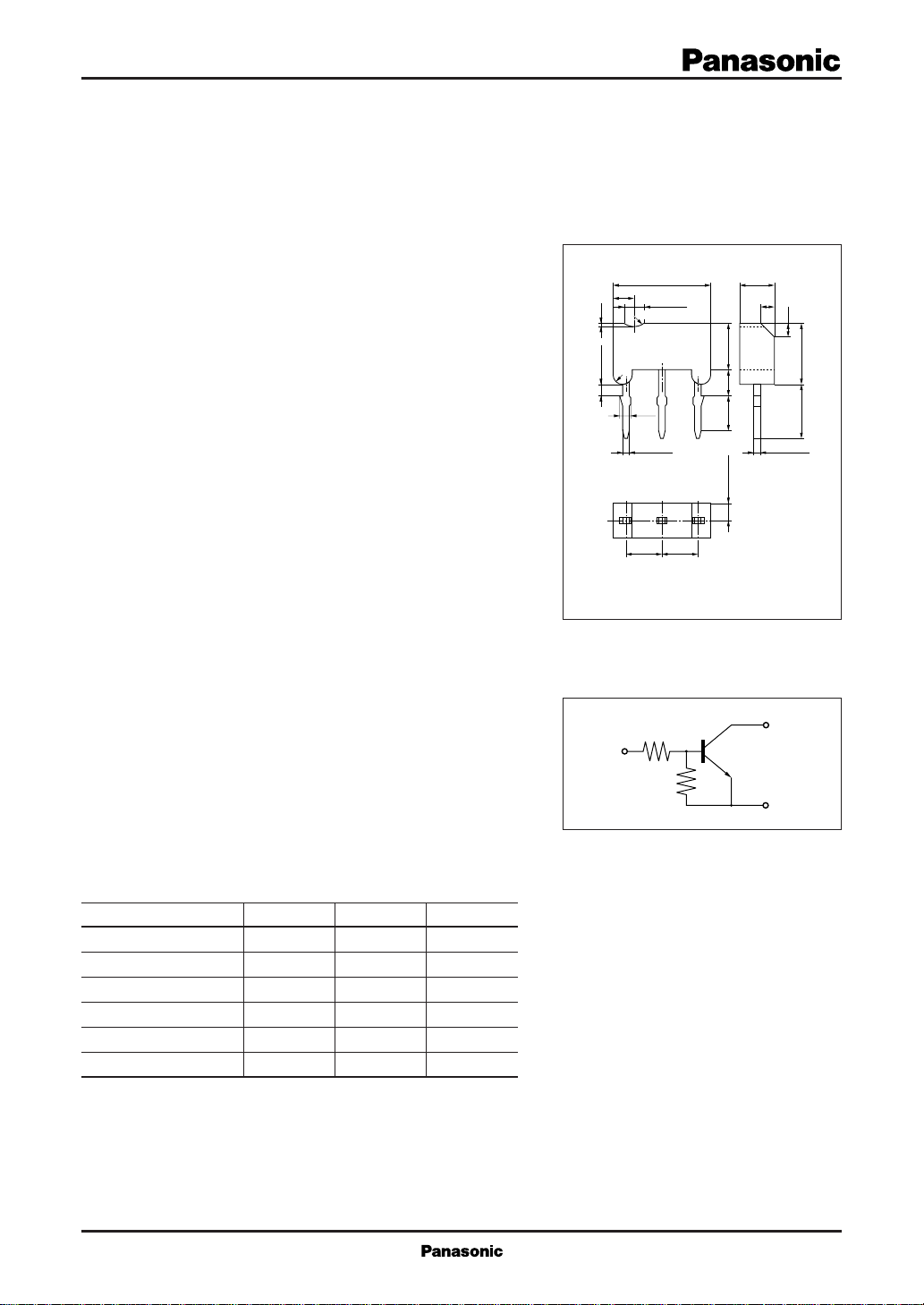
2
6.9±0.1
1.5
1.5 R0.9
0.4
R0.9
R0.7
1.0±0.1
0.85
0.55±0.1 0.45±0.05
2.5 2.5
Internal Connection
2.5±0.1
1.0
3.5±0.1
2.0±0.2
2.4±0.21.25±0.05
123
1:Base
2:Collector
3:Emitter
M Type Mold Package
Unit: mm
1.0
4.1±0.2 4.5±0.1
Absolute Maximum Ratings (Ta=25˚C)
■
Parameter Symbol Ratings Unit
Collector to base voltage V
Collector to emitter voltage
Collector current I
Total power dissipation P
Junction temperature T
Storage temperature T
CBO
V
CEO
C
T
j
stg
50 V
50 V
100 mA
400 mW
150 ˚C
–55 to +150 ˚C
1
UN1211/1212/1213/1214/1215/1216/1217/1218/
Transistors with built-in Resistor
Electrical Characteristics (Ta=25˚C)
■
Parameter Symbol Conditions min typ max Unit
I
Collector cutoff current
I
CBO
CEO
UN1211 0.5
UN1212/1214/121E/121D 0.2
Emitter
cutoff
current
UN1213 0.1
UN1215/1216/1217/1210 I
EBO
UN121F/121K 1.0
UN1219 1.5
UN1218/121L 2.0
Collector to base voltage V
Collector to emitter voltage V
CBO
CEO
UN1211 35
Forward
current
transfer
ratio
UN1212/121E 60
UN1213/1214
UN1215*/1216*/1217*/1210*
h
FE
UN121F/121D/1219 30
UN1218/121K/121L 20
Collector to emitter saturation voltage V
Output voltage high level V
CE(sat)IC
OH
Output voltage low level VCC = 5V, VB = 2.5V, RL = 1kΩ 0.2
UN1213/121K
UN121D VCC = 5V, VB = 10V, RL = 1kΩ 0.2
V
OL
UN121E VCC = 5V, VB = 6V, RL = 1kΩ 0.2
Transition frequency f
T
UN1211/1214/1215/121K 10
UN1212/1217 22
Input
resistance
UN1213/121D/121E/1210
UN1216/121F/121L 4.7
R
1
UN1218 0.51
UN1219 1
UN1211/1212/1213/121L 0.8 1.0 1.2
UN1214 0.17 0.21 0.25
Resistance
ratio
UN1218/1219 0.08 0.1 0.12
UN121D R1/R
UN121E 2.14
UN121F 0.47
UN121K 2.13
VCB = 50V, IE = 0 0.1 µA
VCE = 50V, IB = 0 0.5 µA
VEB = 6V, IC = 0 0.01 mA
IC = 10µA, IE = 0 50 V
IC = 2mA, IB = 0 50 V
VCE = 10V, IC = 5mA
= 10mA, IB = 0.3mA 0.25 V
VCC = 5V, VB = 0.5V, RL = 1kΩ 4.9 V
VCC = 5V, VB = 3.5V, RL = 1kΩ 0.2
VCB = 10V, IE = –2mA, f = 200MHz 80 MHz
2
1219/1210/121D/121E/121F/121K/121L
80
160 460
(–30%)
47
4.7
V
(+30%) kΩ
* hFE rank classification (UN1215/1216/1217/1210)
Rank Q R S
h
FE
160 to 260 210 to 340 290 to 460
2
Transistors with built-in Resistor
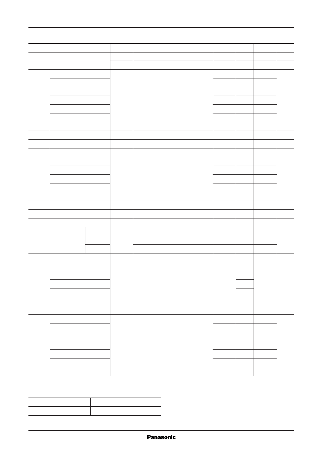
Common characteristics chart
— Ta
P
T
500
)
400
mW
(
T
300
200
100
Total power dissipation P
0
02040 8060 140120100 160
Ambient temperature Ta (˚C
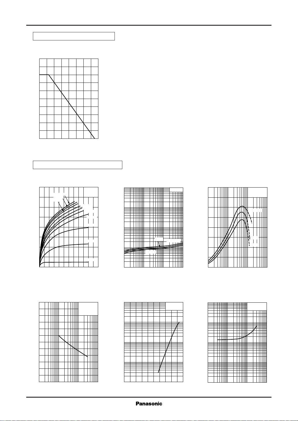
Characteristics charts of UN1211
)
UN1211/1212/1213/1214/1215/1216/1217/1218/
1219/1210/121D/121E/121F/121K/121L
— V
I
C
CE
160
140
)
120
mA
(
C
100
80
60
40
Collector current I
20
IB=1.0mA
0.9mA
0.8mA
0
012210486
Collector to emitter voltage VCE (V
Cob — V
6
)
pF
(
5
ob
4
3
CB
Ta=25˚C
0.7mA
0.6mA
0.5mA
0.4mA
0.3mA
0.2mA
0.1mA
f=1MHz
=0
I
E
Ta=25˚C
V
CE(sat)
100
)
V
(
30
CE(sat)
10
3
1
0.3
0.1
0.03
Collector to emitter saturation voltage V
0.01
0.1 0.3
)
–25˚C
1 3 10 30 100
Collector current IC (mA
IO — V
10000
3000
)
1000
µA
(
O
300
100
— I
25˚C
IN
C
IC/IB=10
Ta=75˚C
VO=5V
Ta=25˚C
hFE — I
C
400
FE
300
200
100
VCE=10V
Ta=75˚C
25˚C
–25˚C
Forward current transfer ratio h
0
13
)
100
30
)
10
V
(
IN
3
1
10 30 100 300 1000
Collector current IC (mA
VIN — I
O
VO=0.2V
Ta=25˚C
)
2
1
Collector output capacitance C
0
0.1 0.3
1 3 10 30 100
Collector to base voltage VCB (V
30
10
Output current I
3
1
0.4
)
Input voltage VIN (V
1.41.21.00.80.6
)
0.3
Input voltage V
0.1
0.03
0.01
0.1 0.3
Output current IO (mA
1 3 10 30 100
)
3
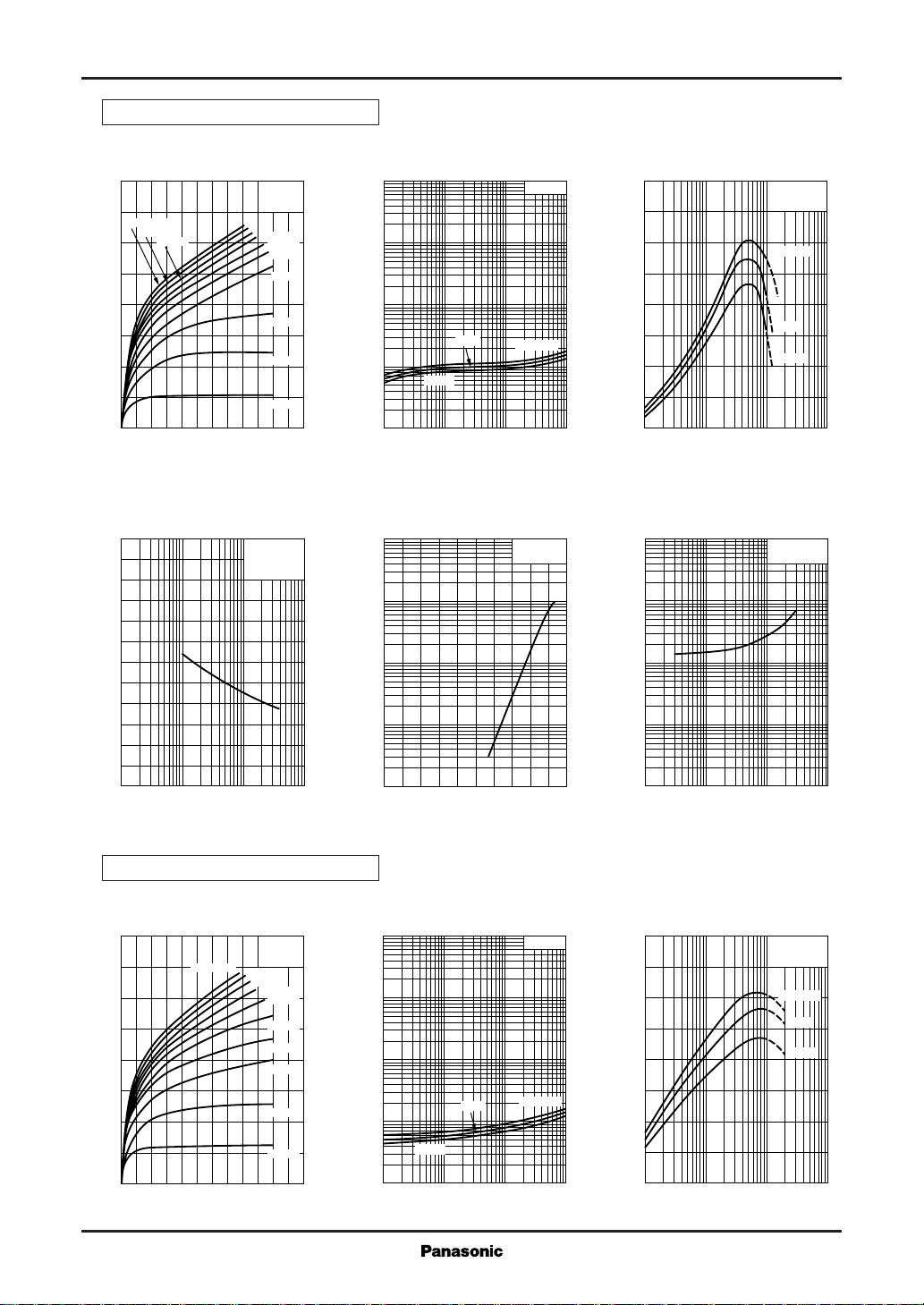
Transistors with built-in Resistor
Characteristics charts of UN1212
UN1211/1212/1213/1214/1215/1216/1217/1218/
1219/1210/121D/121E/121F/121K/121L
— V
I
C
160
140
IB=1.0mA
)
0.9mA
120
mA
(
C
100
Collector current I
0.8mA
80
60
40
20
0
012210486
Collector to emitter voltage VCE (V
Cob — V
6
)
pF
(
5
ob
4
3
CE
CB
Ta=25˚C
0.7mA
0.6mA
0.5mA
0.4mA
0.3mA
0.2mA
0.1mA
f=1MHz
I
=0
E
Ta=25˚C
V
— I
CE(sat)
100
)
V
(
30
CE(sat)
10
3
1
0.3
0.1
0.03
Collector to emitter saturation voltage V
0.01
)
–25˚C
0.1 0.3
1 3 10 30 100
Collector current IC (mA
IO — V
10000
3000
)
1000
µA
(
O
300
100
25˚C
C
IC/IB=10
Ta=75˚C
400
FE
300
200
100
Forward current transfer ratio h
0
13
)
IN
VO=5V
Ta=25˚C
100
30
)
10
V
(
IN
3
1
hFE — I
C
VCE=10V
Ta=75˚C
25˚C
–25˚C
10 30 100 300 1000
Collector current IC (mA
VIN — I
O
VO=0.2V
Ta=25˚C
)
2
1
Collector output capacitance C
0
0.1 0.3
1 3 10 30 100
Collector to base voltage VCB (V
Characteristics charts of UN1213
— V
I
C
CE
160
140
)
120
mA
(
C
100
80
60
40
Collector current I
20
0
012210486
IB=1.0mA
Collector to emitter voltage VCE (V
Ta=25˚C
0.9mA
0.8mA
0.7mA
0.6mA
0.5mA
0.4mA
0.3mA
0.2mA
0.1mA
30
10
Output current I
3
1
0.4
)
)
V
(
CE(sat)
0.03
Collector to emitter saturation voltage V
0.01
)
Input voltage VIN (V
V
CE(sat)
100
30
10
3
1
0.3
0.1
–25˚C
0.1 0.3
1 3 10 30 100
Collector current IC (mA
25˚C
— I
C
1.41.21.00.80.6
)
IC/IB=10
Ta=75˚C
)
0.3
Input voltage V
0.1
0.03
0.01
0.1 0.3
1 3 10 30 100
Output current IO (mA
hFE — I
C
400
350
FE
300
250
200
150
100
Forward current transfer ratio h
50
0
13
10 30 100 300 1000
VCE=10V
Collector current IC (mA
)
Ta=75˚C
25˚C
–25˚C
)
4
 Loading...