

Panasonic UJ35 Installation Manual
LED UV Curing System Aicure SPOT Type
UJ30/35 Series
User’s Manual
ARCT1F510E-2
2011.9 |panasonic-electric-works.net/sunx
LED product safety precautions
LED Product Classification
The light source of the LED head connected to this product is classified as 3B under the
JIS C6802 “Safety of laser products.”
Max output: 780mW Wavelength: 365±5 nm
Class 3B LED Product JIS C6802: 2005
Max output: 940mW Wavelength: 385±5 nm
Class 3B LED Product JIS C6802: 2005
DANGER
Controlling or calibrating this product by other than the procedures stipulated here could
cause exposure to dangerous LED radiation.
・ Do not look directly at LED-UV light, or at LED-UV light reflected in a mirror or
other reflective surface. Doing so could cause eye damage.
・ Install the main unit so that humans are not exposed to LED-UV light.
Exposure could injure the skin or cause other injury.
・ Always turn off the key switch before cleaning the LED head.
Cleaning the head while the switch is on could cause eye damage or injury to the skin.
・ Never disassemble this product.
Disassembling this product could cause exposure to LED-UV light, causing eye
damage or injury to the skin.
・ If there is a risk of the LED-UV light being exposed to UV reflective light, place the
product inside a cover with proper reflectance and heat characteristics to block that
reflected light.
・ When operating the controller, set up the system so that the path of the LED-UV light
is not at eye level.
・ It is strongly recommended that a protective barrier be placed around the product,
so that people cannot approach it while it is operating.
・ Always wear the UV protective goggles when using this product.
・ Never operate this product in a manner not described in this manual. Doing so risks
exposure to LED-UV light.
Safety Precautions for Users
JIS C6802 stipulates user guidelines pertaining to safety precautions to be taken by users
and management standards.
In the case of this product, please implement safety precautions for a class 3B LED
product. See JIS C6802, “Safety of laser products” for details. In the abroad, see the
standard according each country.
ii

LED product safety precautions
Laser products Preventive safety measures for users (summary)
[from JIS “Safety of laser products”]
Required item/
Article
Laser
safety manager
10.1
Remote
interlock
10.2
Key control
10.3
Beam attenuator
10.4
Emission
indication device
Warning
indication
10.5
Beam path
10.6
Specular
reflection
10.7
Eye protection
10.8
Protective
clothing
10.9
Training
10.10
Classification
Class 1 Class 1M
Not necessary, but it is recommended that one be
appointed in the case of applications where laser beams
can be directly observed
Not necessary
Same as
Not necessary
No necessary
items
No necessary
items
Class 3B for
Class 1M
Same as
Class 3B for
Class 1M
Same as
Class 3R for
Class 1M
Class 2 Class 2M
Not necessary
Not necessary Remove the key when not in use
Not necessary
Not necessary
Same as
Not necessary
No necessary
items
No necessary items
No necessary items
No necessary
items
Class 3B for
Class 2M
Same as
Class 3R for
Class 2M
Same as
Class 3B for
Class 2M
Class 3R Class 3B Class 4
Not necessary in
the case of
visible light
beams.
Necessary in the
case of invisible
light beams.
Avoid careless irradiation during
Indicates that
laser is operating
at an invisible
wavelength.
Terminate beam at end of effective length
Necessary for all operators and maintenance
Indicates that laser is operating
Avoid unintended reflection
Necessary if it is not possible to
execute technical and management
permissible exposure) is exceeded
Necessary
Connected to a room or door
circuit
use
Follow warning indication
preventive measures
procedures, and if MPE (max.
Sometimes
necessary
personnel
instructions are
Specific
necessary
iii

LED product safety precautions
Safety features
This product is equipped with the following safety features, based on JIS C6802 “Safety of laser
products.”
■Remote interlock
UV irradiation can be stopped by opening the INPUT terminal “INTERLOCK (11)” on the rear of the
controller. It is shorted with a shorting bar as a factory default.
■Control by a key switch
The controller unit of this product is started via a key switch. Ensure that the key is removed while this
product is not in use.
■LED radiation emission warning
Turning ON the key switch enables the irradiation of LED UV light, which turns on the irradiation
warning indicator on the front panel of the controller. If the LED connection cable is longer than 2 m, or if
the controller unit is installed in an invisible part of the equipment, another warning indicator needs to be
provided in a visible location around the LED head.
(OUTPUT terminals “+5V” (23) and “COM” (24) on the rear of the controller output signals when the
key switch is turned ON.)
Stays on during irradiation
The emitting channels are indicated by a red light, either still
or flashing.
■Emergency reset
If an error occurs, eliminate the cause and then hold down “SET” for more than one second to clear the error.
iv

LED product safety precautions
Emission hole
Labels
The LED irradiation warning labels (shown below specified by JIS C6802) shown below are attached to
the LED heads before this product is shipped from the factory. Warning labels in Chinese that comply
with GB standards and those in English that comply with IEC/EN standards are also included.
■Warning labels in Japanese (JIS)
Description
Warning mark Emission hole location indication label
■Description
Description and mark label
Emission hole location indication label
LED head
■Warning labels in Chinese (GB standards)
If this product is used in China, apply the labels shown below over the Japanese labels.
■Warning labels in English (IEC/EN standards)
If this product is used outside Japan or China, attach the labels shown below over the Japanese
labels.
v
Safety precautions
DANGER
The purpose of the following caution indications is to ensure the safe and correct use of this product,
in order to protect users from injury and prevent property damage.
The caution indications to prevent possible human injury and property damage caused by incorrect use are
classified by “DANGER” and “WARNING” depending on their degree and severity.
All caution indications are critical for ensuring safety and must be strictly observed.
DANGER
WARNING
Symbol examples
Prohibited
Mandatory
Mandatory
Do not disassemble
Failure to observe the instructions can result in death or serious injury.
Failure to observe the instructions can result in injury or property damage.
This symbol denotes a
The left-hand example denotes “Do not disassemble”.
●
This symbol denotes a
The left-hand example denotes “Mandatory”.
●Do not use this product in a space in which combustible gases may be present.
(To avoid the risk of explosion.)
●Do not dispose of this product in a fire.
(To avoid the risk of batteries or electronic parts exploding.)
●While the LED is lit do not look at direct or reflected radiation, and do not allow anyone
to approach.
(To avoid the risk of injury or inflammation to eyes and skin.)
●Always wear UV protective goggles and protective gear when using this product.
(To avoid the risk of risk of injury or inflammation to eyes and skin.)
●Never try to disassemble or modify this product.
(To avoid the risk of generating abnormal heat or smoke. Also, disassembling the LED head
may expose eyes and skin to LED-UV radiation, resulting in injury or inflammation.)
●To prevent the generation of abnormal heat or smoke, always use this product with an
adequate margin of safety with respect to its guaranteed characteristics and performance
values.
●Do not touch the terminals while they are electrically powered.
(To avoid the risk of electric shock.)
●Make sure to connect the power cable and connectors securely.
(To avoid the risk of generating abnormal heat or smoke.)
●Make sure to plug in the AC adapter securely.
(To avoid the risk of generating abnormal heat or smoke.)
Prohibited
action.
Mandatory
WARNING
action or an
Instruction
.
vi
Prohibited
●Never insert any foreign substances such as liquid, flammable materials, or metals inside
the product. (To avoid the risk of generating abnormal heat or smoke.)
●Never perform any setup work (e.g., connection, disconnection) with the power cable
plugged in. (To avoid the risk of electric shock.)
●Never place anything on top of the product or obstruct the ventilation openings in any
way. (To avoid the risk of burning due to overheating.)

Precautions for use
■ General precautions
・ Never connect any LED head, connection cable, AC adapter, or UV sensor to the main unit, other
than those designated by Panasonic. Otherwise, any failure, loss, or damage that may occur will not
be covered under warranty.
・ Never try to disassemble or modify the product, or to alter its internal settings. Any failure or
damage that occurs after disassembling or modifying the product will not be covered under
warranty.
■ Installation environment
・ Ambient temperature Controller: 0 to +35°C (with no condensation)
LED head: +5 to +35°C (with no condensation)
・ Ambient humidity: 30 to 85% RH (at 25°C, with no condensation)
・ A location free of dirt, smoke or soot, conductive dust, and corrosive or flammable gases, where
there is no risk of exposure to water, oil, or chemicals
・ A location not subject to sudden temperature changes, or to vibration and physical shock
・ A location not exposed to direct sunlight
■ Power supply
・ Supply electric power of 100 to 240 V AC (frequency: 50/60 Hz).
・ Supply electric power of 5 to 28 V DC to the input/output terminals.
・ The supplied power cable is for use in Japan, at 100 V. If using this product outside Japan, make
sure to use a suitable cable with the appropriate plug, certified for use in the particular country.
・ Do not connect this product to a power supply that is shared with equipment that includes an electric
motor or other high-power usages. Use a separate power supply and make sure to provide a
protection circuit (e.g., a fuse).
・ Take care to prevent excessive static electricity accumulation.
・ If using multiple units of this product, do not tie their AC adapters together in a bundle. Otherwise,
the AC adapters may overheat, resulting in failure.
・ If the product is to remain unused for any length of time, disconnect the power plug from the power
socket.
■ Wiring
・ If any device connected to this product is connected to a DC induction load (motor or relay), connect
a noise absorption device (e.g., noise suppressor) on the side of the load.
・ When connecting an external power source to the input/output terminals, make sure that the polarity
is correct.
・ Make sure to perform wiring so that no physical or electrical load is added to the connection cable.
Also, avoid bending too close (less than 80 mm) to the base (connector part) and make sure that the
radius of bends is at least 33 mm.
・ Make sure to hold the connector (plug) part while connecting or disconnecting the power plug.
■
If the connection cable is longer than 2 m, or if the product is installed inside a larger item of
equipment, set up a display near the LED head so that the “LED radiation warning” can be readily
seen. If you use OUTPUT terminals “+5V” (23) and “COM” (24) at the rear of the controller, these
will output a signal when the power is switched ON.
vii

Precautions for use
■ Setup
・ Check that the rubber feet of the product are always horizontally level. Never incline the product,
or position it on its side, or upside down. Otherwise, overheating may occur, resulting in failure
and damage.
・ Never place anything on top or below the product, or obstruct the ventilation openings in any way.
Otherwise overheating and burning may occur. Provide for sufficient ventilation space around the
product: Top: 50 mm; Sides: 20 mm; Rear: 80 mm.
■ Precautions when powering ON
・ Check that all connections are correct before powering ON.
■ Other precautions
・ When disposing of this product, it should be treated as industrial waste.
Warranty Period
・ The Warranty Period for this product (excluding LED head) is 3 years from either the date
of purchase or the date on which the product is delivered to the location specified by the
Buyer. However, the Warranty Period shall be valid only until 42 months from the date of
manufacture which includes a maximum of 6-month distribution period. The warranty
period for the LED head extends until one year from the time of delivery, or until 5,000
hours of cumulative irradiation, whichever is sooner.
Extent of Warranty
・ In the event of any failure or defect in the product or non-conformity of specifications due
to the reasons solely attributable to the Seller, Seller shall remedy such malfunctioning or
defective product at its own cost in one of the following ways to be selected by SELLER:
(i) repair such product, (ii) replace such product, (iii) supply of replacement parts.
However, this Warranty shall not cover the damages or defects that arise due to the reasons
any of the followings.
1. Specifications, standards or handling procedures specified by the Buyer.
2. Modifications to the structure, performance or specifications performed by a
party other than the Seller after the date of purchase or the date on which
the product is delivered.
3. Phenomena that could not have been foreseen with the technology that was
put into practical use at the time of purchase.
4. Exceeding the ranges, conditions, circumstances or environment described
in the Manuals or Specification sheet.
5. Damages that could be avoided if Seller’s product have the functions and
structures generally accepted in the industry, when incorporating the
product in to Buyer’s product.
6. Natural disasters or an Act of God.
7. Consumable goods such as batteries and relays, or optional accessories such
as cables.
viii

Precautions for use
・ SELLER SPECIFICALLY DISCLAIMS ALL IMPLIED WARRANTIES OF
MERCHANTABILITY AND/OR FITNESS FOR A PARTICULAR USE OR
PURPOSE, AS WELL AS LIABILITY FOR INCIDENTAL, SPECIAL, INDIRECT,
CONSEQUENTIAL OR OTHER DAMAGES RELATING TO THE PRODUCT.
Product EOL (“end of life”)
・ Please understand that production of this product may be discontinued at any time for a
variety of possible circumstances. Note that repair services are not provided after a
product is discontinued.
ix

Contents
1 Features of the ANUJ 3000/3500................................1
2 Product components....................................................3
3 Parts names and functions...........................................4
4 Installation..................................................................6
4.1 Installation conditions..............................................6
4.2 General guidelines for irradiation distance and UV
intensity..................................................................7
5 Getting started.............................................................9
5.1 Hooking up the connection cable.............................9
5.2 Connecting the LED ................................................ 9
5.3 Connecting the external control signals.................. 11
5.4 Connecting the AC adapter ....................................12
5.5 Power on operation................................................12
6 Operation modes.......................................................13
6.1 Operation mode (default mode when power is turned
on)........................................................................13
1) Setting irradiation conditions..............................14
2) Timer irradiation.................................................14
3) Continuous irradiation........................................15
4) Irradiation using an external start signal.............15
5) Display of head management information..........16
6) Panel lock function.............................................16
6.2 UV measurement and Auto tuning mode................17
1) Measuring UV intensity. ................................... 17
2) Auto tuning .......................................................18
6.3 Default settings mode.............................................19
6.4 Timing chart...........................................................20
1) Batch irradiation.................................................20
2) Individual irradiation ......................................22
7 External control.........................................................24
7.1 External input/output control.....................................24
7.2 Serial communication control...................................26
RS-232C terminal specifications..........................26
Communication specifications..............................26
Commands and responses.....................................27
Command/response format...................................27
Block check code BCC (H) (L).............................27
Control commands................................................28
Support commands...............................................28
Error codes ...........................................................28
Data areas.............................................................29
7.3 Communications address map...................................30
Address for reading ..............................................30
Address for writing...............................................34
WRITE procedure.................................................38
7.4 Setup tool application for UJ35.................................39
Operation from a PC.............................................39
8 Warning indications ..................................................46
Temperature warning............................................46
Time warning........................................................46
Error codes ...........................................................47
9 Safety measures ........................................................48
9.1 Safety circuit..........................................................48
10 Specifications..........................................................49
10.1 Outline of specifications.......................................49
Controller specifications......................................49
Head specifications.............................................50
UV sensor specifications.....................................52
11 Dimensions..............................................................53
12 Option and spare parts list.......................................54
12.1 Options and spare parts.......................................54
12.2 How to replace the lens unit................................56
12.3 Fitting the mounting bracket ...............................56
13 Troubleshooting......................................................57
Manual revision history ..................................................58
x

1 Features of the ANUJ 3000/3500
UV
separately for
proce
sses 1 to 4.
1 to 4.
The ANUJ 3000/3500 is an UV curing device that quickly hardens UV resins (inks, adhesives, and coatings)
via irradiation with UV light from an LED light source. The focused application of UV radiation to UV resins
coated on minute surfaces (2 to 3 mm dia.) such as the lenses of CD, MD, and DVD players, and the LCD
panels of notebook PCs, enables precise adhesion.
■High-power irradiation: 10,000 mW/cm2 (with ANUJ6423 lens)
Higher radiation intensity and a wider range of applications. Shorter production cycles.
■Long LED life: 20,000 hours (LED life: Total irradiation time before UV intensity falls to 70% of
initial value)
At least six times longer LED life than a comparable lamp model, enabling reduced running costs.
■UV curing without temperature increases
Uses a single 365-nm LED UV light source that does not emit any infrared radiation, eliminating the risk of
heat damaging the workpiece.
■UV intensity stabilization
UV intensity is kept constant, even if the ambient or LED temperature changes.
■Easy-to-install LED head
At 12 mm dia. by 50 mm len., the LED is easy to mount on a jig. Mounting the LED head in place reduces
overheating and increases UV intensity.
■No cooling fan, enabling cleanroom use
There is no need to deal with exhaust.
■Programmable UV irradiation with four independently controlled heads
Each LED head can be controlled independently. The heads can also be controlled all together or in
combination. Up to eight different operation programs can be stored for each channel, including one program
for the constant intensity irradiation and seven programs composed of up to 10 steps each.
Program examples
Simple mode
1 Features of the ANUJ 3000/3500
intensity
Constant
intensity
Time
Up to 7 programs can be set.
Program 1
Program 7
Interval (closed)
[Lamp type]
Four units need to be installed
Fiber
Process 1 Process 2 Process 3 Process 4
One controller handles processes
Process 1 Process 2 Process 3 Process 4
1

Features of the ANUJ 3000/3500
The
■Universal design for easy operation
Easy operation has been achieved by the product’s universal design, including the large-sized color LED
display with a high level of visibility and the operation switches located at optimal locations.
After connecting the head, UV irradiation can be started simply by selecting a channel (CH), setting the UV
power (%) and irradiation time (TIME), and then pressing [EMISSION].
■Multiple safety features
Circuit breaks and short circuits of the LED head are automatically detected. If the LED overheats due to high
ambient temperature or other reason, it turns itself off. UV irradiation can be brought to an emergency by
opening INPUT terminal “INTERLOCK” (11) on the rear of the controller. Irradiation can also be stopped by
short-circuiting “STOP” (9) and “COM” (12).
■Detachable terminal blocks for external connection
The detachable terminal blocks facilitate connections with external equipment.
■Universal power supply
The supplied AC adapter is a universal type for 100 to 240 V ± 10%.
(The supplied AC adapter power cable is 100 V AC cable for use in Japan
2

2 Part names and functions
Controller
Optional parts (sold separately)
LED head
AC adapter
100 V (AC) power cable for use in Japan only
Instruction Manual
Standard lens
Connection cable x1
3

3 Part names and functions
Front of the controller
UV sensor (option)
Rear of the controller
AC adapter
DC output indicator LED
4

Part names and functions
●Front
(1) EMISSION switch
(9) Display unit
(8) Operation switch
(7) UV check switch
(only UJ35)
(6) UV sensor
connection port (only UJ35)
●
Rear
(13) CH1-CH4 LED head
connecting connector
(14) Protective seal
(12) AC adapter connector
Description Function Remark
(1) EMISSION switch
(2) READY indicator Indicates that UV irradiation is enabled (ready to start).
(3) CH1-CH4
operation switch
(4) CH1-CH4
selector/indicator
(5) Key operated
power switch
(6) UV sensor
connection port
(7) UV check button Views/calibrates values measured by the special UV sensor UJ35 only
(8) Operation unit switch
(9) Display unit
(10) Input/output terminal
block
(11) RS232C connector Connects a PC, PLC, or other external device with RS232C. UJ35 only
UV is irradiated and stopped by selected irradiating CH head. Red lamp is turned on
during UV irradiation.
Selects the LED head channels for irradiation.
Red = irradiation, green = standby, yellow = error
Commences/finishes operation of the controller.
Connects the special UV sensor. UJ35 only
Specifies irradiation conditions (intensity and time), replacement time settings, and
initial values, and switches the display.
Displays irradiation conditions (intensity and time), replacement time settings, head
temperature, and initial values.
Connects a PLC, foot switch, or other external device
(2) READY indicator
(3) CH1-CH4 operation switch
(4) CH1-CH4 selector/indicator
(5) Key operated power switch
(10) Input/Output terminal block
(11) RS232C connector
(only UJ35)
(12) AC adapter connector Connects the special AC adapter.
(13) CH1-CH4 head
connecting connector
(14) Protective seal Protects connectors.
Cconnects LED heads.
5
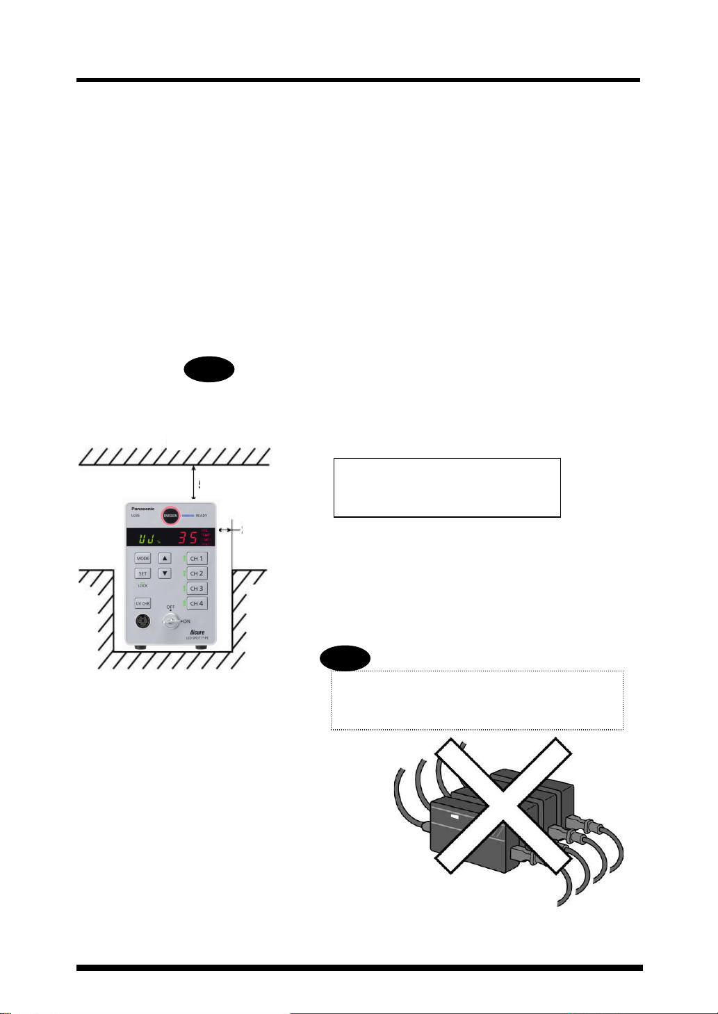
4 Installation
If using more than one controller, do not bundle
Ensure that there is enough space
Warning
WarningWarning
Warning
Warning
WarningWarning
Warning
Install and set up the product according to the following conditions.
4.1 Installation conditions
1) Ambient temp.: Controller: 0 to +35°C
Head: +5° to +35°C
2) Relative humidity: 30 to 85% (at 25°C, no condensation)
3) When setting up the controller, make sure that its rubber feet are
horizontally level.
4) To prevent damage due to overheating, make sure that the area around the
controller is free of any obstructions.
5) The dimensions of the controller are 80 mm (L) × 130 mm (H) × 145 mm
(D), but remember that the controller will have one or more LED heads
attached during use. The radius of the LED head connector cable should
be no less than 33 mm, otherwise the cable may become damaged.
Never place anything on top or below the controller, or obstruct the
ventilation openings in any way. Otherwise, overheating and burning may
occur.
Wall
Approx. 50 mm
Approx. 20 mm
Wall
above and on the sides of the
controller.
the supplied AC adapters together. Otherwise, the
AC adapters may overheat and fail.
6

Installation
WD=50
Irradiation area
4.2 General guidelines for irradiation distance and UV intensity
Fix the LED head to a jig at the appropriate distance from the workpiece, according to the size of the area to be
irradiated (irradiation diameter) and the required UV intensity.
General guidelines for work distance (WD) and UV intensity are offered below.
■ UV intensity data (typical characteristics)
[UV intensity level: 100% Room temperature: 25°C With a cooling device attached]
* See page 11 for the dimensions of the cooling device.
LED head: ANUJ6170
ANUJ 6423
ANUJ 6423 (φ3mm)
ANUJ 6423 ANUJ 6423
14,000
)
12,000
2
)
2
10,000
(mW/cm
8,000
6,000
4,000
UV強度(mW/cm
UV intensity
2,000
0
-5 -4 -3 - 2 -1 0 1 2 3 4 5
Irradiation area
ANU J64 24
ANU J64 24 (φ4mm)
ANU J64 24 AN UJ6 424
12,000
)
2
10,000
)
2
(mW/cm
8,000
6,000
4,000
UV intensity
UV強度(mW/cm
2,000
0
-5 -4 -3 -2 - 1 0 1 2 3 4 5
Irradiation area
ANUJ 6426
ANUJ 6426 (φ6mm)
ANUJ 6426 AN UJ6 42 6
6,000
)
2
5,000
)
2
4,000
(mW/cm
3,000
2,000
UV intensity
UV強度( mW/cm
1,000
0
-5 -4 -3 - 2 -1 0 1 2 3 4 5
Irradiation area
ANUJ 6428
ANUJ 6428 (φ8mm)
ANUJ 6428 ANUJ 6428
4,000
)
2
3,500
)
2
3,000
(mW/cm
2,500
2,000
1,500
1,000
UV強度(mW/cm
UV intensity
500
0
-5 -4 -3 -2 -1 0 1 2 3 4 5
Irradiation area
ANUJ 6420
ANUJ 6420 (φ10mm)
ANUJ 6420 A NUJ64 20
2,000
1,800
)
2
)
1,600
2
1,400
(mW/cm
1,200
1,000
800
600
UV強度(mW/cm
400
UV intensity
200
0
-7-6-5-4-3-2-10 1 2 3 4 5 6 7
Irradiation area
照射範囲(mm)
照射範囲(mm)
照射範囲(mm)
照射範囲(mm)
照射範囲(mm)
(mm)
(mm)
(mm)
(mm)
(mm)
WD=10
WD=12
WD=15
WD=20
WD=25
WD=30
WD=50
WD=10
WD=15
WD=20
WD=25
WD=30
WD=40
WD=50
WD=10
WD=15
WD=20
WD=25
WD=30
WD=40
WD=10
WD=15
WD=20
WD=25
WD=30
WD=50
WD=10
WD=12
WD=14
WD=16
WD=20
Irradiation distance vs
intensity and area
If an irradiation area of 6 mm diameter
is irradiated at an intensity of 500 mW/cm
or higher, draw lines on the graph at ±3 mm
and 500 mW/cm2. Find the irradiation
distance line that covers the area surrounded
by the drawn lines. In this example,
the ANUJ6428 head can maintain
an intensity of 500 mW/cm2 or higher
for a 6-mm diameter area
by setting the irradiation distance to 50 mm.
ANUJ 6428
ANUJ 6428 (φ8mm)
ANUJ 6428 ANUJ 6428
4,000
3,500
)
2
)
2
2
3,000
2,500
(mW/cm
2,000
1,500
1,000
UV強度(mW/cm
500
0
-5 -4 -3 -2 - 1 0 1 2 3 4 5
照射範囲(mm)
(mm)
WD=10
WD=15
WD=20
WD=25
WD=30
WD=40
WD=50
7

Installation
U V
強 度
( m W
/
c m
)
U V
強 度
( mW
/
c m
)
U V
強 度
( m W
/
c m
)
U V
強 度
( mW
/
c m
)
U V
強 度
( mW
/
c m
)
U V
強 度
( m W
/
c m
)
U V
強 度
( m W
/
c m
)
U V
強 度
( m W
/
c m
)
U V
強 度
( m W
/
c m
)
Cylindrical lens data (typical characteristics)
■ Rod lens data (typical characteristics) ■
Length direction
長手方向
ANUJ6450S
2,000
WD=10
1,800
WD=15
1,600
2
WD=20
1,400
1,200
1,000
800
600
400
200
0
-10 -8 -6 -4 -2 0 2 4 6 8 10
照射範 囲(m m)
ANUJ6475S
2,000
1,800
WD=10
1,600
WD=15
2
WD=20
1,400
1,200
1,000
800
600
400
200
0
-10 - 8 -6 -4 -2 0 2 4 6 8 10
照射範囲(mm)
12,000
WD3
10,000
WD5
2
WD7
8,000
WD10
WD15
6,000
WD20
WD25
4,000
WD30
2,000
0
-5 -4 -3 -2 -1 0 1 2 3 4 5
照射範囲(mm)
8,000
7,000
WD3
WD5
2
6,000
WD7
5,000
WD10
WD15
4,000
WD20
WD25
3,000
2,000
1,000
0
-5 -4 -3 -2 -1 0 1 2 3 4 5
照射範囲(mm)
Width direction
幅方向
2,000
1,800
WD=10
WD=12
1,600
2
WD=15
1,400
1,200
1,000
800
600
400
200
0
-4 -3 -2 -1 0 1 2 3 4
照射範囲(mm)
2,000
1,800
WD=10
1,600
WD=12
2
1,400
WD=15
1,200
1,000
800
600
400
200
0
-4 -3 -2 -1 0 1 2 3 4
照射範囲(mm)
Side-view lens
Side-view lens data (typical characteristics)
6,000
WD5
5,000
WD10
2
WD15
4,000
WD20
WD25
3,000
WD30
WD40
2,000
1,000
0
-5 -4 -3 -2 -1 0 1 2 3 4 5
照射範囲(mm)
4,000
WD5
3,500
WD10
WD15
2
3,000
WD20
WD25
2,500
WD30
WD40
2,000
1,500
1,000
500
0
-5 -4 -3 -2 -1 0 1 2 3 4 5
照射範囲(mm)
1,000
800
2
600
400
200
0
-5 -4 -3 -2 - 1 0 1 2 3 4 5
WD5
WD10
WD15
WD20
WD25
WD30
WD40
照射範囲(mm)
8

Warning
WarningWarning
Warning
Connector
Lens prote
ctor cap
Connector
Connector
After connecting the necessary cords, lastly plug in the power cord.
This section describes the steps up to turning on the power.
5.1 Hooking up the connection cable
Plug the connection cable (for the LED head) into its connection port.
Connection cable
Plug the female side of the connection cable into the main unit. Plugging in
the wrong side (the male connector) could bend the connector pins or cause
other issues.
5.2 Connecting the LED
Connecting the head
LED head
5 Getting started
Connection cable
Main unit side
LED side
9

Getting started
Warning
WarningWarning
Warning
Warning
WarningWarning
Warning
Rear panel
<Procedure>
1. Plug in the connection cable.
2. Connect the LED head to the connection cable.
3. Remove the protective cap from the LED head.
<Reference> Heat dissipation device (aluminium)
(A metal fixture attached to the head)
Set the LED jig in place.
2-M4 (5mm D)
M6 (5mm D)
The rise in LED temperature depends on the duration
of irradiation time and the interval between irradiations.
If the temperature increases beyond a certain point an
alarm will be generated. In the event of such
overheating, increase the size of the heat dissipation
fixture, or add fins to it.
If the LED head is not fixed to a jig, the LED head can become very hot during irradiation. For this reason, do
not touch the head directly with your hands during irradiation.
10

5.3 Connecting the external control signals
The external control connectors on the back of the controller (two blocks of
12 pins) are removable.
External control connectors (12 pin × 2)
MINI COMBICON Plug 12P (Phoenix Contact MC 1.5/12-ST-3.5)
(Osada OS-85-12P)
Getting started
Compatible wire (stranded)
Size
AWG#24 to 16 0.2 to 1.25 mm2
Tightening torque: 0.22 Nm to 0.25 Nm
Conductor section area
Cover stripping length
6 to 7 mm
11
 Loading...