

Panasonic UJ20 Installation Manual
Aicure UV Curing System
LED Spot Type
UJ20 Series
User’s Manual
Thank you for your purchase of the Aicure LED spot UV curing system.
In order to use the system correctly, please read this User's Manual carefully befor e use.
After you have read it, store it in a secure location, and refer back to it if you have any
uncertainties.
LED product safety precautions
LED Product Classification
The light source of the LED head connected to this product is classified as 3B
under the JIS C6802 “Safety of laser products.”
Max output: 330mW Wavelength: 365±5nm
Class 3B LED Product JIS C6802 : 2005
DANGER
Controlling or calibrating this product by other than the procedures stipulated here
could cause exposure to dangerous LED radiation.
- Do not look directly at LED-UV light, or at LED-UV light reflected in a mirror or
other reflective surface. Doing so could cause eye damage.
- Install the main unit so that humans are not exposed to LED-UV light.
Exposure could injure the skin or cause other injury.
- Always turn off the key switch, before cleaning the LED head.
Cleaning the head while the switch is on could cause eye damage or injury to the
skin.
- Never disassemble this product. Disassembling this product could cause
exposure to LED-UV light, causing eye damage or injury to the skin.
- If there is a risk of the LED-UV light being exposed to UV reflective light, place
the product inside a cover with proper reflectance and heat characteristics to
block that reflective light.
- When operating the controller, set up the system so that the path of the LED-UV
light is not at eye level.
- It is strongly recommended that a protective barrier be placed around the product
so that people cannot approach it while it is operating.
- Always wear the UV protective goggles when using this product.
- Never operate this product in a manner not described in this manual. Doing so
risks exposure to LED-UV light.
Safety Precautions for Users
JIS C6802 stipulates user guidelines pertaining to safety precautions to be taken by
users and management standards. In the case of this product, please implement
safety precautions for a class 3B LED product. See JIS C6802, “Safety of laser
products” for details. In the abroad, see the standard according each country.
ii
Safety features for LED products
Safety features
This product is equipped with the following safety features based on JIS C6802 Safety of laser
products.
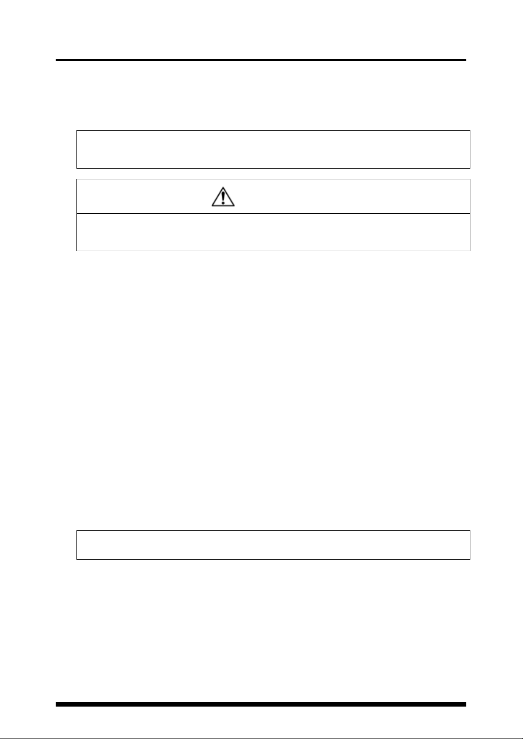
Remote interlock
UV radiation can be stopped by opening INPUT terminal “EMER (11)” on the rear of the
controller. It is shorted with a shorting bar as a factory default.
Control by a key switch
The controller unit of this product is started via a key switch. Ensure that the key is removed
while this product is not in use.
LED radiation warning
Turning ON the key switch enables the irradiation of LED UV light, which turns on the
irradiation warning indicator on the front panel of the controller. If the LED connection cable is
longer than 2 m, or if the controller unit is installed in an invisible part of the equipment,
another warning indicator needs to be provided in a visible location around the LED head.
[OUTPUT terminals “+5V” (23) and “GND” (24) on the rear of the controller output signals
when the key switch is turned ON.]
Stays on during irradiation.
The emitting channel number flashes.
Emergency reset
If an error occurs, eliminate the cause and then hold down “SET” for one or two seconds to
clear the error. Or, hold down “SET” for five seconds or more to forcibly clear the error.
iii
Safety features for LED products
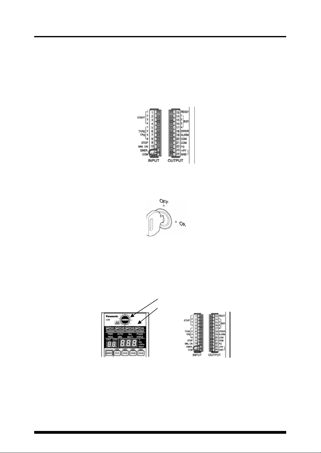
Labels
The LED irradiation warning labels shown below specified by JIS C6802 are attached to the LED
heads before this product is shipped from the factory. Warning labels in Chinese that comply with
GB standards and those in English that comply with IEC/EN standards are also included.
Warning labels in Japanese (JIS)
Description Warning mark
Emission hole location
indication label
Label locations
Description and mark label
Emission hole location indication label Emission hole
LED head
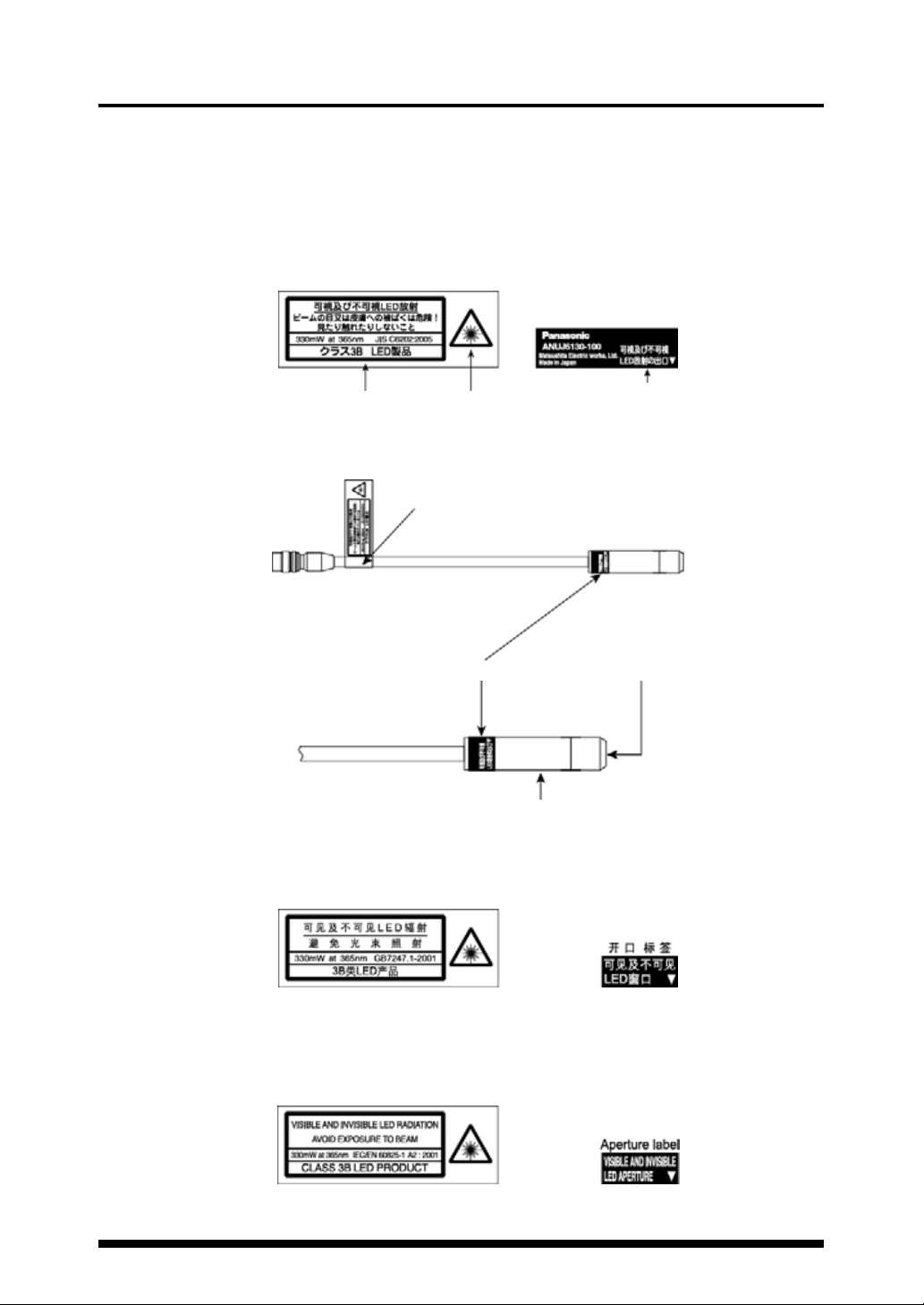
Warning labels in Chinese (GB standards)
If this product is used in China, attach the labels shown below over the Japanese labels.
iv
Warning labels in English (IEC/EN standards)
If this product is used outside Japan or China, attach the labels shown below over the
Japanese labels.

Safety precautions
The purpose of the following caution indications is to ensure the safe and correct use of this
product in order to protect users from injury and prevent property damage.
The caution indications to prevent possible human injury and property damage ca used by
incorrect use are classified into
degree and severity.
All caution indications are critical for ensuring safety and must be strictly
observed.
“DANGER” and “WARNING” depending on their
DANGER
WARNING
Symbol examples
:
This symbol denotes a Prohibited action.
The left-hand example denotes “Do not disassemble”.
:
This symbol denotes a Mandatory action or an Instruction.
z
The left-hand example denotes “Mandatory”.
While the LED is lit, protect your eyes and skin from direct exposure to the
Prohibited
Wear protective the UV goggles and other protective gear during operation.
Mandatory
Never disassemble, repair, or modify this product in any way other than
Do not
disassemble
Make sure to disconnect the power plug from the outlet after use of this
Pull the plug, not the cord, to unplug this product.
Mandatory
Prohibited
Do not use any input power supply outside the specified range.
If the power cord or plug is damaged, or if contact between the plug and
Do not use this product in a place where temperatures vary widely or dew
Do not use this product in a place where a large vibration or impact can be
Do not hold the controller by hand during use. (This is not a hand-held type.)
Failure to observe the instructions can result in death or serious injury.
Failure to observe the instructions can result in injury or property damage.
DANGER
light and any strong reflections.
Failure to do so may result in inflammation of the eyes or skin.
This product uses a Class 3B LED source.
Failure to do so may result in inflammation of the eyes or skin.
The wavelengths of some UV rays generated by this product are 365 nm. Therefore, make sure
to wear UV-filtering goggles
specified in this User Manual.
Such actions may result in an accident or injury.
WARNING
product.
Insulation deterioration may result in electrical shock or fire.
A short circuit may result in elec trical shock or fire.
Such actions may result in fire.
receptacle is loose, do not use the product.
Such actions may result in electrical shock, short circuit, or fire.
condensation occurs.
Such actions may result in product malfunction.
applied.
Such actions may result in product malfunction.
Such actions may result in electrical shock.
v
Precautions for use
1) Do not connect this product to any power supply outside the power supply voltage and frequency
range indicated on the main unit and in this User’s Manual. Otherwise, this product may be
damaged. The power cable supplied with this product is a 100 V cable for use in Japan only.
When using this product outside Japan, use a power cable that has been certified by applicable
standards and has a plug shape that fits the receptacle used in each country.
2) Use this product under the following operating conditions; otherwise, the product life may be
shortened.
Ambient temperature: Controller: 0 to 35°C
Head: 5 to 35°C
Relative humidity: 85% or lower (with no condensation)
Operation environment: Use this product in a location with minimum dirt, dust, or oil mist under
no extreme temperature changes, severe vibrations, or shock.
Storage temperature: -10 to +60°C at 85% or lower relative humidity (with no condensation)
3) Do not place anything on the controller or block the air vents around this product to prevent the
occurrence of burns due to overheating.
4) When using more than one controller, do not bundle the supplied AC adapters together. The AC
adapters may overheat and damage the products.
5) When handling the LED head, do not touch the lens or LED with bare hands.
If a foreign substance adheres to the lens or LED, it can cause the UV intensity to decrease and
the curing performance to degrade. If bare hands touch the lens or LED, wipe it clean with
alcohol.
6) Be careful not to drop or apply shock to the LED head. Doing so may damage this product.
7) Do not repeatedly bend the LED head or the connection cable, as this may result in breakage.
If any part of the LED head is broken, the whole LED head must be replaced.
8) Set the rubber feet of this product on a flat horizontal surface.
Do not tilt this product or put it on its side or upside down during use. The product may overheat
and be damaged.
9) Noise superimposed on the power supply may cause the LED head or control power supply to
malfunction. In such cases, install an insulating transformer or a noise filter.
10) Do not share a power supply with an motor, dielectric machinery, or equipment that consumes
high power.
11) Do not use any cable other than the supplied connection cable to connect the LED head to the
controller.
12) Ensure that the connection cable a pprox. 80 mm from the connector is kept free from flexing
stress and the joint between the connector and the cable is kept free from tension. Otherwise, the
cable may be broken.
13) If the LED connection cable is longer than 2 m, or if the controller unit is installed in an invisible
part of the equipment, a warning indicator needs to be provided in a visible location around the
LED head. Use “+5V” (23) and “GND” (24) on the rear of the controller as outputs for the indicator.
They output signals when the key switch is turned ON.
Warranty
- This product will be repaired free of charge if it malfunctions under normal use conditions within one
year of delivery.
Note that, however, the warranty does not apply to malfunctions attributable to your company,
consumables, and/or unavoidable problems resulting from such occurrences as natural disasters.
- The warranty for the LED head is valid for one year from delivery or 5,000 hours of total irradiations,
whichever comes first.
Compensation for Production
- We will not compensate the user for losses due to production shutdowns and/or defects caused by
any malfunction of this product.
vi

Contents
1 Features of the ANUJ5024 Aicure........................1
2 Product components............................................. 3
3 Part names and functions.....................................4
Switch panel .....................................................5
Simple mode setting.........................................6
Operation flowchart......................................... 10
4 Installation........................................................... 11
4.1 Installation conditions.................................... 11
4.2 General guide for irradiation distance and
UV intensity.................................................... 12
5 Getting started.................................................... 14
5.1 Hooking up the connection cable...................14
5.2 Connecting the LED.......................................14
5.3 Connecting the external control signals......... 16
5.4 Connection of the AC adapter........................17
5.5 Power-on operation .......................................17
6 Operation modes................................................ 18
6.1 Auto mode (Set by default when the power is
turned on) ....................................................19
6.2 Manual (MNL) mode......................................23
6.3 Irradiation mode (ALL/MULTI).......................26
6.4 Start signal mode (PULSE/STATUS)
(PULSE/STATUS) ........................................27
6.5 LED replacement time (x100hrs)
setting mode.................................................. 27
6.6 UV intensity (W/cm
calibration mode............................................ 28
6.7 Product type (TYPE) switching mode............30
6.8 Program (PROG) setting mode..................... 30
6.9 Power (PWR) mode ......................................32
6.10 Setting lock function ......................................32
6.11 Irradiation mode setting................................. 33
ALL irradiation mode (batch irradiation)........ 33
MULTI irradiation mode
(individual irradiation).................................... 35
2
) measurement/
7 External control....................................................37
7.1 External input/output control..........................37
7.2 Serial communication control.........................39
RS232C terminal specifications ....................39
Communication specifications.......................39
Commands and responses ...........................40
Control commands........................................40
Error codes....................................................41
Command/response format...........................41
Utility software (for control from a PC) ..........42
8 Warning displays.................................................43
Temperature warning.......................................43
Time warning...................................................43
Error codes......................................................44
9 Safety measures..................................................45
9.1 Safety circuit ..................................................45
10 Specifications ....................................................46
Overall specification........................................46
11 Dimensions........................................................48
12 Options and spare parts list...............................49
12.1 Product numbers for placing orders...............49
12.2 How to replace the lens .................................50
13 Troubleshooting.................................................51
Manual revision history............................................52
vii

1 Features of the UJ20: Aicure
The UJ20: Aicure is an UV curing system that quickly hardens UV resins (inks, adhesives, and
coatings) via irradiation with UV light from an LED light source. Focused irradiation of UV resins
coated on minute surfaces (2 to 3 mm dia.) such as the lenses of CD, MD, and DVD players, and
the LCD panels of notebook PCs and the like, with UV radiation enables precise adhesion.
High-power irradiation: 8,000 mW/cm2 (When the Power Mode is on and an
ANUJ61523 head is used)
Higher intensity and wider range of irradiation reduces the production cycle time.
Long LED life: 20,000 hours (LED life: Total irradiation time before the UV
intensity becomes 70% of the initial value)
This LED life is over six times that of our conventional lamp model and reduces the running
cost.
■ UV curing without temperature increases
A single 365-nm LED UV light source is used, which does not include infrared radiation.
This eliminates the risk of heat damage to the workpiece.
■ Stable UV intensity
UV intensity is kept constant, even if the ambient or LED temperature changes.
■ Easy-to-install LED head
At 12 mm dia. x 50 mm len., the LED is easy to mount on a jig. Mounting the LED head in
place reduces overheating and increases UV intensity.
■ No cooling fan construction allows the use in a clean room
There is no need to deal with exhaust.
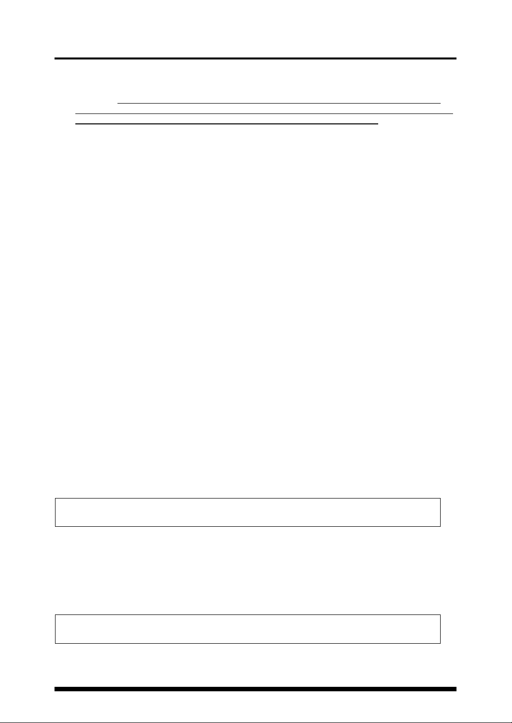
Programmable UV irradiation with four individually controlled heads
Each LED head can be independently controlled. The heads can also be controlled all
together or in combination. Up to 16 different operation programs can be stored for each
channel, including one program for the constant intensity irradiation and 15 programs
composed of up to 10 steps each.
Program examples
Simple mode Up to 15 programs can be set.
Program 1 Program 15
UV intensity
Constant
intensity
Time
Interval (closed)
[Lamp type] Four units need to be
Fiber:
installed separately for
processes 1 to 4.
Process 1 Process 2 Process 3 Process 4 Process 1 Process 2 Process 3 Process 4
[UJ20] One controller handles
processes 1 to 4.
1
Features of the ANUJ5024 Aicure
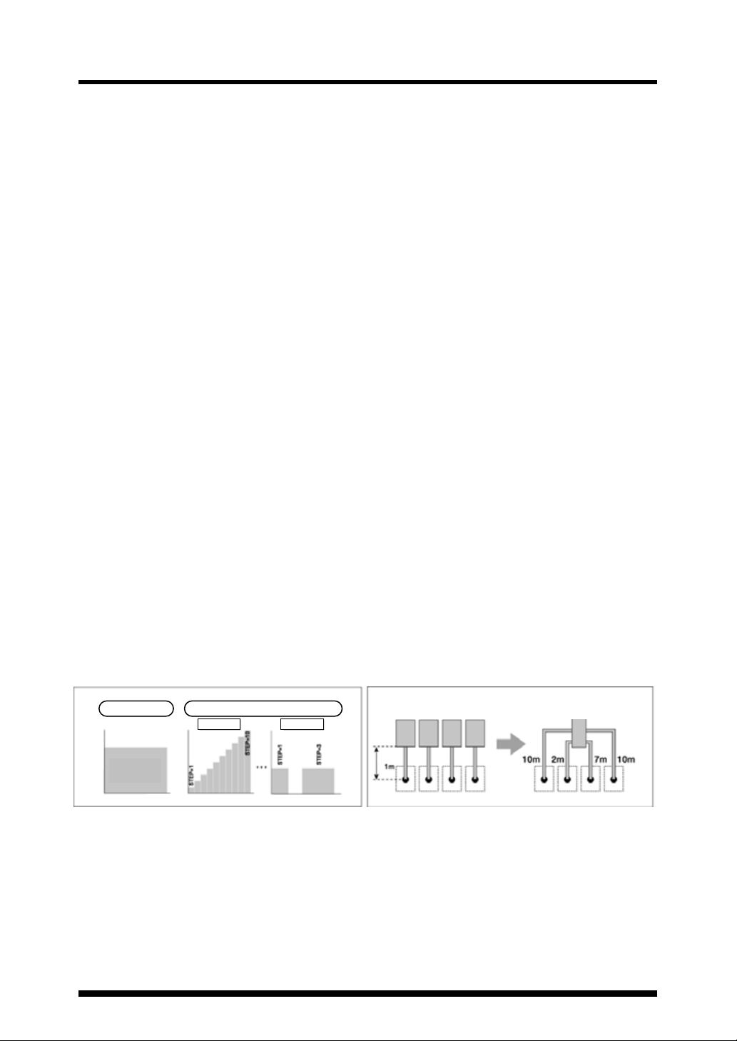
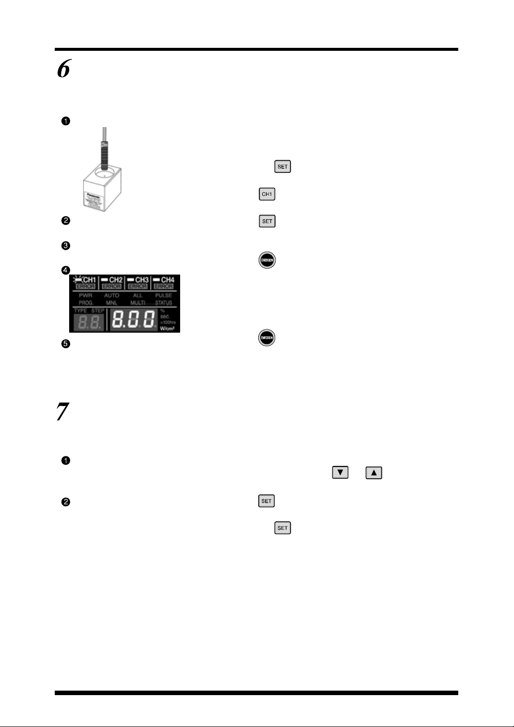
Universal design for easy operation
Easy operation has been achieved by the product’s universal design, including the large-sized
color LED display with a high level of visibility and the operation switches located at optimal
locations.
In simple mode, UV irradiation can be started simply by setting the UV power and irradiation
time, and then pressing [EMISSION].
(1) Press [SET], choose
TYPE 00 (simple mode),
and press [CH1] (the
target head).
(2) Set the irradiation
intensity by pressing [T]
and [S] switches, and
press [SET].
Multiple safety features
This product has a function to detect breaks and short-circuiting of the LED head. The LED is
automatically turned off if it overheats due to ambient temperature rise or other conditions. UV
irradiation can be brought to an emergency stop by opening INPUT terminal “EMER (11)” and
short-circuiting “STOP (9)” and “COM (12)” on the rear of the controller during irradiation.
Detachable terminal blocks for external connection
The detachable terminal blocks facilitate connections with external equipment.
Universal power supply
The supplied AC adapter is a universal type for 100 to 240 V AC ± 10%.
(The supplied AC adapter power cable is a 100 V AC cable for use in Japan only.)
(3) Set the irradiation time
by pressing [T] and [S]
switches, hold down [SET],
and press [EMISSION] to
start UV irradiation.
2
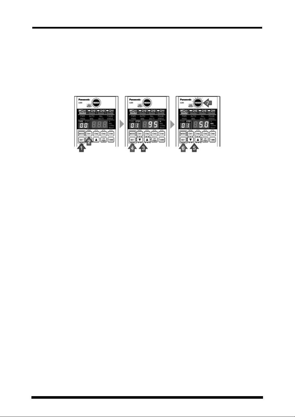
2 Product components
Please check the contents of your package.
Basic package
Controller
Optional components
AC adapter (100-240VAC)
100 V AC power cable for use in Japan only
When using this outside Japan, use a power
cable that has been certificated by applicable
standards and has a plug shape that fits the
receptacle in each country.
User’s Manual
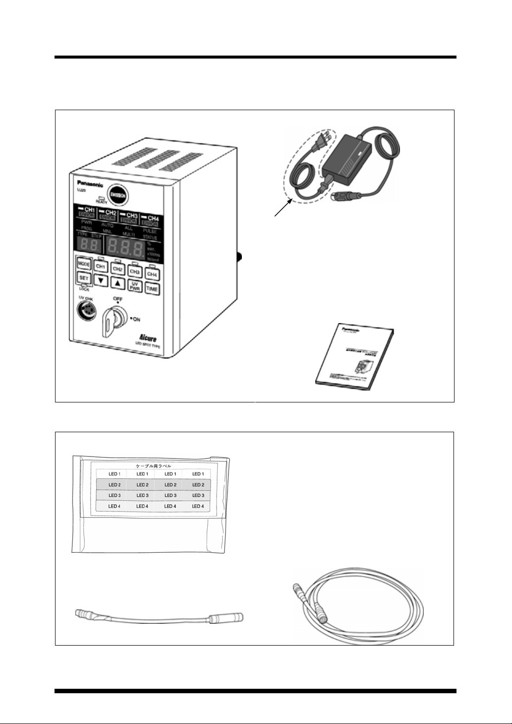
Cable labels (attached to the connection cable)
LED head (with lens)
Connection cable
3
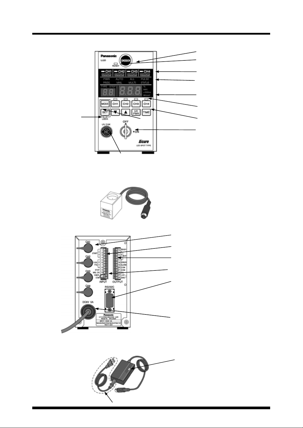
3 Part names and functions
Front of the controller
Key lock indicator
UV sensor (Option)
Rear of the controller
Supplied AC adapter
UV sensor connection port
LED connection cable connector
Input connector (Pin Nos. 1 to 12)
Output connector (Pin Nos. 13 to 24)
Interlock line (Pin Nos. 11 and 12)
Communication connector (RS232C, 9 pins)
Connector for the supplied AC adapter (6 V DC)
DC output indicator LED
EMISSION switch
READY indicator
Status indicator
Operation setting indicator
Data display (7 segments)
CH selector/indicator
Setting switches
Key operated power switch
100 VAC power cable for use in Japan only.
4
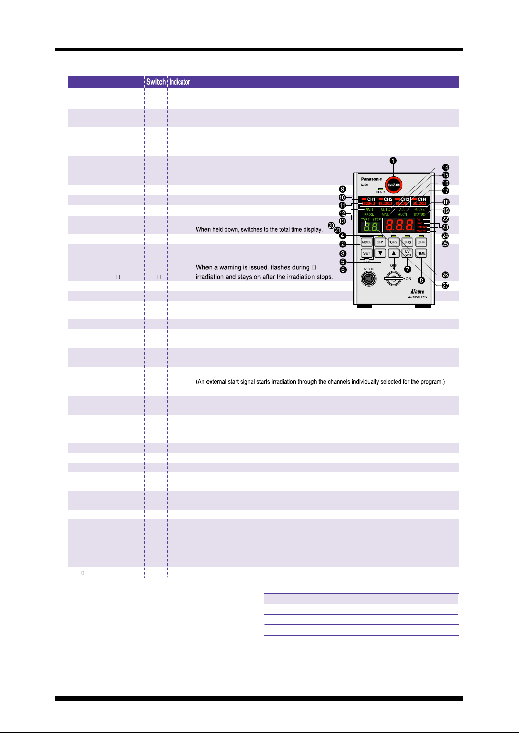
Part names and functions
Switch panel
No. Name Description
1 EMISSION ○ Starts/stops MNL irradiation, and starts/emergency-stops AUTO irradiation.
2 MODE ○ When held down, switches between the setting and AUTO modes.
3 SET ○ When held down, switches to the TYPE00 setting mode.
4 CH1 - 4 ○ Switches the display and selects the channel.
5 ▼○ Decreases the setting value.
6 ▲○ Increases the setting value.
7 UV PWR ○ Switches to the UV intensity level display.
8 TIME ○ Switches to the UV irradiation time display.
9 READY Green Stays on while AUTO irradiation is ready.
10 CH1 - 4 *Green Stays on while the LED head is connected.
11 ERROR Red Turned on when an error occurs.
12 PWR Green Abbreviation for "power".
13 PROG. Green Abbreviation for "program". Stays on during program setting.
14 AUTO Green Auto mode (Set by default when the power is turned on)
15 MNL Green Abbreviation for "manual". Stays on in manual mode (Top of the setting mode).
16 ALL Green Stays on in the batch irradiation mode.
17 MULTI Green Stays on in the individual irradiation mode.
Red The indicator stays on during irradiation.
Cancels the entry.
Accepts the entry.
When held down in setting mode, saves the accepted settings in memory.
Green Flashes in the AUTO mode or setting mode.
Lit when the program selection is accepted.
*Red Flashes during irradiation.
Orange
Turned on when the power mode is turned on.
Flashes when an external signal switches the mode to manual.
(The channels selected for the program start irradiation simultaneously.)
18 PULSE Green Stays on in pulse start mode.
19 STATUS Green Stays on in status start mode.
20 TYPE Green Stays on while the product type is displayed.
21 STEP Green Stays on while the program step is displayed.
22 % Green Stays on while the UV intensity level is displayed.
23 sec. Green Stays on while the irradiation time is displayed.
24 X100hrs Green Stays on while the total irradiation time is displayed and during the process of setting the
25 W/cm2 Green Stays on while the maximum UV intensity is displayed.
26 Display (3 digits) Green 0 - 100 %
27
Display (2 digits) Green Product type: "00" to "15"
(Pressing EMISSION on the controller starts simultaneous irradiation.)
(Irradiation starts at the leading edge of the start signal.)
(Irradiation starts at the leading edge of the start signal, and stops at the trailing
edge of the start signal input during irradiation.)
(During AUTO radiation: Counting down During MNL radiation: Counting up)
LED replacement time. (Stays on after the time warning is issued in AUTO mode.)
0,0.1 - 99.9, 100 - 999 sec
0.00 - 9.99, 10.0 - 99.9, 100 - 999 X100hrs
000, 0, 0.01 - 9.99 W/cm2
Green "On", "OFF" (during PWR mode setting)
*
Temp. < Standard temp.: Slow
Standard temp. ≦ Temp. < Warning level temp.:Mid
Warning level temp. ≦ Temp. < Abnormal temp.:Quick
Speed of flashing during irradiation
5
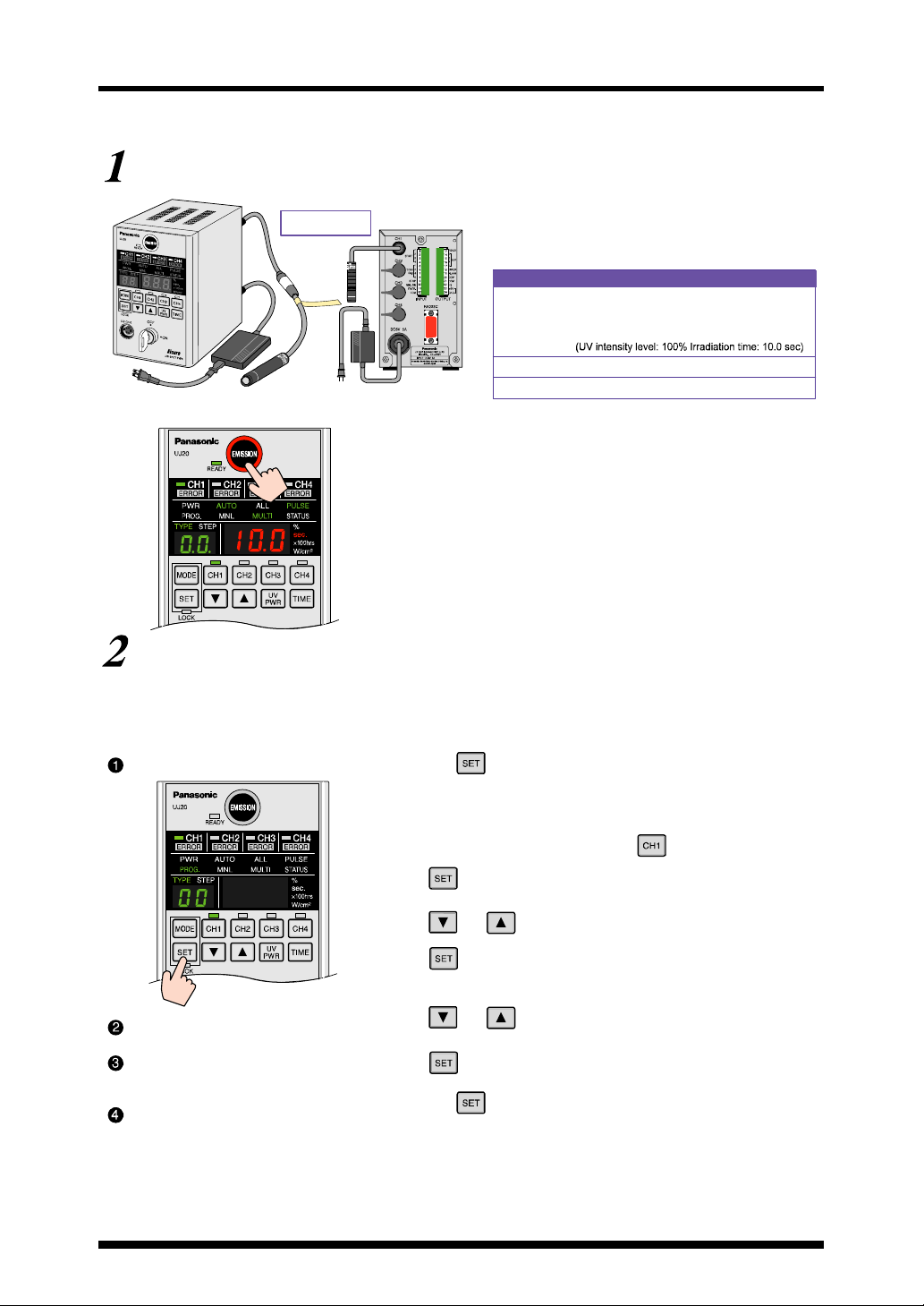
Part names and functions
Simple mode setting
Irradiation with default settings
* The factory-default settings are shown below.
Connection
Front panel Rear panel
1. Connect the LED head to CH1.
2. Connect the AC adapter.
3. Insert the key into the key switch and turn it to the right (to power on
the controller).
After the startup display appears, a beep sounds and the READY
indicator is lit.
* Press UV PWR to display the UV intensity level, and press it again to display
the LED head temperature.
* Press TIME to display the irradiation time.
4. Press EMISSION. A beep will sound and irradiation will start.
The EMISSION indicator stays on during irradiation.
When completed, irradiation stops with a beeping sound, and the
READY indicator is turned on.
Configuration
l Controller l AC adapter
l LED head l Lens l Connection cable
Default settings
Type TYPE00 :Program for irradiation at constant intensity
: Number of heads: 1 (CH1)
: STEP 1 is set.
Irradiation mode ALL: Batch irradiation
Start mode PULSE: Pulse signal start
How to change the default settings
Note: The setting change will be cancelled if the panel is left untouched during the setting change operation.
Note: Press MODE to cancel the setting change and go back to AUTO mode.
Note: The display flashes during the setting change operation.
Note: Hold down SET during setting to save accepted settings in memory and go back to AUTO mode.
Switch to setting mode.
Select CH1.
Set the UV intensity level of
CH1.
Set the irradiation time of CH1.
6
1. Hold down .
(The AUTO mode display switches to the TYPE00 setting mode display.)
2. Press the target channel switch.
(The indicator of the channel selected for the program will be turned on.)
(You don't need to select the channel because has already been selected
by default.)
Press .
(To accept the selection of CH1 and go to the UV intensity level setting screen)
3. Press and until the value to be set is displayed.
(Hold the switches down to accelerate the increment/decrement speed.)
4. Press .
(To accept the UV intensity level and go to the irradiation time setting screen)
5. Press and until the value to be set is displayed.
(Hold the switches down to accelerate the increment/decrement speed.)
6. Press . (To accept the irradiation time and go back to the setting mode)
(You can hold down SET, skipping the step that requires pressing it.)
7. Hold down .
(To save the UV intensity level and the irradiation time in memory, and go back
to AUTO mode)
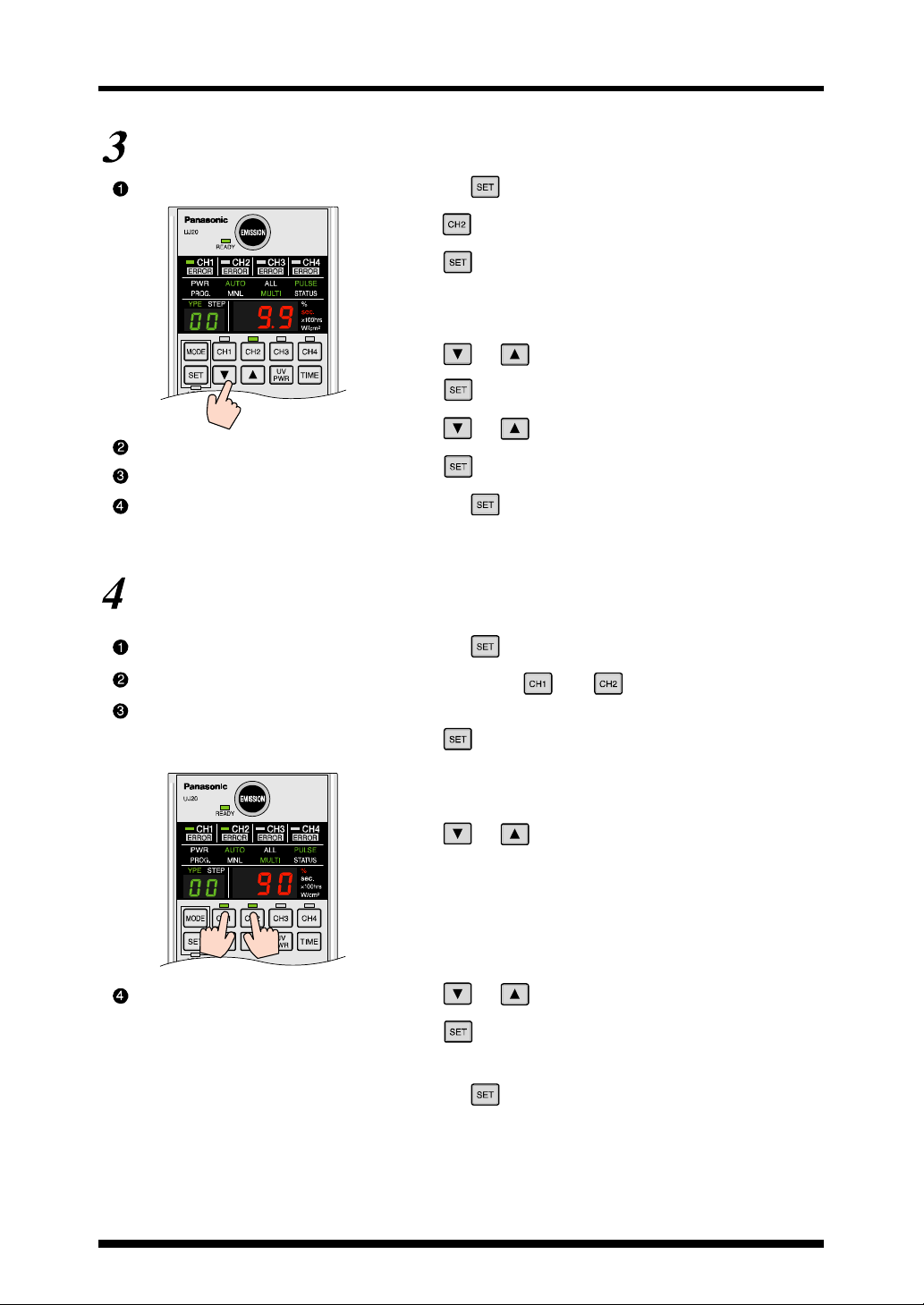
Part names and functions
How to switch the irradiation channel (e.g. From CH1 to CH2)
Switch to setting mode.
Select CH2.
Set the UV intensity level of CH2.
Set the irradiation time of CH2.
1. Hold down .
(The AUTO mode display switches to the TYPE00 setting mode display.)
2. Press . (Press the target channel switch.)
(The indicator of the channel selected for the program will be turned on.)
3. Press .
(To accept the selection of CH2 and go to the UV intensity level setting screen)
* If you hold down SET rather than press it, only the channel change will be
saved in memory, and the controller will go back to AUTO mode. (The other
settings will not be changed.)
4. Press and until the value to be set is displayed.
(Hold the switches down to accelerate the increment/decrement speed.)
5. Press .
(To accept the UV intensity level and go to the irradiation time setting screen)
6. Press and until the value to be set is displayed.
(Hold the switches down to accelerate the increment/decrement speed.)
7. Press . (To accept the irradiation time and go back to the setting mode)
(You can hold down SET, skipping the step that requires pressing it.)
8. Hold down .
(To save the UV intensity level and the irradiation time in memory, and go back
to AUTO mode)
(e.g. Make the same settings for CH1 and CH2)
Switch to setting mode.
Select CH1 and CH2.
Set the UV intensity level.
Set irradiation time.
1. Hold down .
(The AUTO mode display switches to the TYPE00 setting mode display.)
2. While holding down , press .
(While holding down one CH switch, press the other switches for channels to
be selected one by one.)
3. Press .
(To accept the selections of CH1 and CH2 and go to the UV intensity level
setting screen.)
* If you hold down SET rather than press it, only the channel change will be
saved in memory, and the controller will go back to AUTO mode. (The other
settings will not be changed.)
4. Press and until the value to be set is displayed.
(Hold the switches down to accelerate the increment/decrement speed.)
When two or more channels are selected, the display shows the setting for the
flashing channel. In this condition, the displayed setting can be changed and
applied to all selected channels.
5. Press SET.
(To accept the UV intensity level and go to the irradiation time setting screen)
* If you hold down SET rather than press it, the selections of the channels and
the UV intensity level setting will be saved in memory, and the controller will
go back to AUTO mode.
6. Press and until the value to be set is displayed.
(Hold the switches down to accelerate the increment/decrement speed.)
7. Press . (To accept the irradiation time and go back to the setting mode)
* You can hold down SET, skipping the step that requires pressing it, to save
the UV intensity level and irradiation time settings in memory and go back to
AUTO mode.
8. Hold down .
(To save the UV intensity level and the irradiation time in memory, and go back
to AUTO mode)
#How to make the same settings for two or more channels
7

Part names and functions
#How to make different settings for two or more channels
(e.g. Make different settings for CH1 and CH2)
Switch to setting mode.
Select CH1.
Set the UV intensity level.
Set irradiation time.
Select CH2.
1. Hold down .
2. Press .
3. Press .
(To accept the selection of CH1 and go to the UV intensity level setting screen)
4. Press and until the value to be set is displayed.
(To accept the UV intensity level and go to the irradiation time setting screen)
5. Press .
(To accept the UV intensity level and go to the irradiation time setting screen)
6. Press and until the value to be set is displayed.
7. Press .
(To accept the CH1 irradiation time and go back to the setting mode)
8. Press .
9. Press .
(To accept the selection of CH2 and go to the UV intensity level setting screen)
Set the UV intensity level.
Set irradiation time.
10.Press and until the value to be set is displayed.
11.Press .
(To accept the UV intensity level and go to the irradiation time setting screen)
12.Press and until the value to be set is displayed.
13.Press .
(To accept the CH2 irradiation time and go back to the setting mode)
Select CH1 and CH2.
14.While holding down , press .
(The CH1 LED will be turned on, and the CH2 LED indicator will flash.)
Save the settings in memory
15.Hold down .
and end the setting mode.
(To save the selections of CH1 and CH2, the UV intensity level, and the irradiation time in
memory, and go back to AUTO mode)
8
Part names and functions
How to measure the UV intensity (e.g. CH1)
You can check the UV intensity of the simple mode program by using the optional UV sensor.
Prepare for the measurement.
Switch to setting mode.
Select CH1.
Measure the UV intensity.
End the measurement.
1. Connect the sensor to UV CHK.
2. Align the center of the LED head with the center of the lightreceiving section of the UV sensor.
3. Hold down .
(The AUTO mode display switches to the TYPE00 setting mode display.)
4. Press .
5. Press .
#((The selection of CH1 will be accepted, and irradiation will be ready
(if the sensor is connected).)
6. Press .
(UV irradiation will start, and the measured value will be indicated on the
display.)
7. Press .
(Irradiation will stop.)
How to manually calibrate the UV intensity (e.g. CH1)
You can calibrate the UV intensity set for the simple mode program based on the measured intensity.
Measure the UV intensity and
calibrate it.
End the calibration.
1. Follow procedures 6-(1) to (4) to measure the UV intensity, and
then calibrate it by pressing and .
(The calibrated UV intensity will be displayed.)
2. Press .
(To accept the calibrated UV intensity level and stop irradiation)
3. Hold down .
(To save the UV intensity level of CH1 in memory and go back to AUTO
mode)
9
Part names and functions
(Pag
)
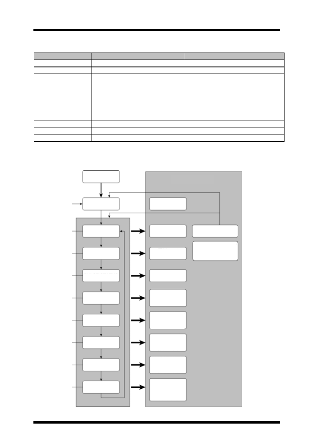
Operation flowchart
Mode switching operation table
Controller panel display Mode name How to switch from AUTO mode
AUTO AUTO mode Set by default when the power is turned on
MNL
MNL flashing
ALL/MULTI Irradiation mode MNL mode + One press of MODE switch
PULSE/STATUS Start signal mode MNL mode + Two presses of MODE switch
X100hs LED replacement time setting mode MNL mode + Three presses of MODE switch
W/cm2 UV intensity measurement/calibration mode MNL mode + Four presses of MODE switch
TYPE Product type setting switch mode MNL mode + Five presses of MODE switch
PROG Program setting mode MNL mode + Six presses of MODE switch
PWR Power mode ON/OFF switch mode MNL mode + Seven presses of MODE switch
*1
In manual mode (EMISSION start), it is possible to externally start irradiation by turning on the external signal to “MNL ON”.
(MNL indicator will be turned on.)
*2
In external manual mode (external start), it is possible to start irradiation by pressing EMISSION on the controller. (MNL
indicator will flash.)
Flowchart
1
*
Manual (MNL) mode (EMISSION start) Hold down MODE switch.
2
*
External manual (MNL) mode (External start)
Power on
Turn on the signal to INPUT terminal “MNL ON”
on the rear panel. (Cannot be switched to another
mode while MNL is flashing.)
Mode name
AUTO
MNL
ALL/MULTI
PULSE/STATUS
X100hrs
W/cm2
TYPE
PROG
AUTO mode
(Page 19)
Manual (MNL) mode
(Page 23)
Irradiation mode
(Page 26)
Start signal mode
(Page 27)
LED replacement
time setting mode
(Page 27)
UV intensity
measurement/
calibration mode
e 28
Product type setting
switch mode
(Page 30)
Program setting
mode
(Page 30)
External MNL ON
External manual
(MNL) mode
(Page 26)
PWR
Power mode
ON/OFF switch
mode
(Page 32)
10
 Loading...