

Panasonic ue-608030 Operation Manual
Operating Instructions
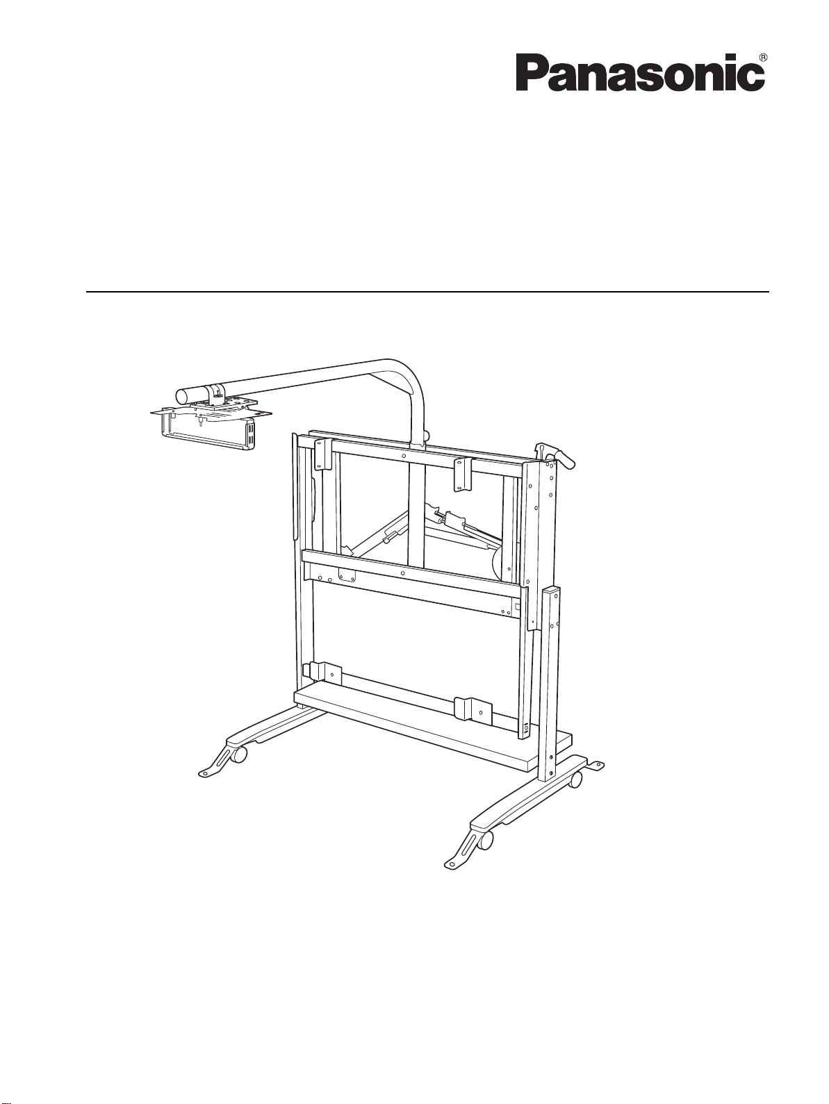
Up/Down Wall Mount Kit
Up/Down Stand Kit
(For elite Panaboard)
Model No. UE-608030
UE-608031
UE-608032
Installation Manual Included (for qualified service personnel)
• To assemble this unit, please refer to the Installation Manual on pages 14 through 39.
• Before operating this unit, please read these instructions completely and keep them carefully for future
reference.
• This unit i s designed for installation by a qualified ser vicing dealer.
Installation performed by non-authorized individuals could cause safety-related problems with the operation of
this equipment.
For U.S.A. only:
• To locate the closest authorized dealer in your area, please call 1-800-449-8989.
Introduction
Attach your sales receipt here
Introduction
Introduction
Thank you for purchasing the Panasonic up/down wall mount kit and up/down stand kit.
For optimum performance and safety, please read these instructions carefully.
Feature Highlights
The up/down wall mount kit and up/down stand kit are used solely with the Panasonic elite Panaboard.
These kits allow the elite Panaboard to be placed at the exact height desired.
They enable the elite Panaboard to be placed at a low height when it is going to be used for small children or at a
higher height when it is going to be used for older children. In addition, the projector can be installed at the top of
the stand for use so that the screen surface will be less likely to be in the shadows, making the elite Panaboard
easy to use.
When using up/down stand kit, the large-sized casters provided enable the projector arm part to rotate so that
even a large board and stand system can be easily moved from one place to another.
Things you should keep a record of
For your future reference
Date of purchase
Serial number
Dealer’s name
Dealer’s address
Dealer’s tel no.
Exemption of Liability
Panasonic System Networks Co., Ltd. is not responsible for accidents or injuries caused by, but not limited to,
the following:
1. Altering the device or improper installation construction.
2. Using the device for purposes beyond its intended use.
3. Earthquake, fire, flood, tidal wave, hurricane, lightning or other natural phenomena.
4. Natural aging of the building or similar phenomena.
2 Operating Instructions

Table of Contents
Table of Contents
Table of Contents
Operating Instructions
For Your Safety..............................................................................................4
Usage..............................................................................................................7
Included Acc es so ries.... .. ............. .. ........................... .. .. ............. ... .......................... .. ... ............ 7
Names and Uses o f th e Pa rts ............. .......................... .. ... ............. .. ........................... .. .. ........ 7
Checkpoints When Installing the Equipment on the Table Plate......................................... 8
Securing the S ta n d ....................... .. ........................... .. .. ............. ... .......................... .. ... ............ 9
Moving the elite Panaboard Up or Down................................................................................ 9
Using the elite Panaboard...................................................................................................... 10
Adjusting the Screen Image .................................................................................................. 10
Moving the Sta n d................... ... .. ............. .. ... ............. .. ........................... .. .............................. 11
Appendix ......................................................................................................13
Troubleshooting ..................................................................................................................... 13
Installation Manual (for qualified service person nel)
For Your Safety............................................................................................14
Product Configur ati on ....................... ... .. ................. ................. .. ................16
Packing Configuration ...........................................................................................................16
Included Acc es so ries.... .. ............. .. ........................... .. .. ............. ... .......................... .. ... .......... 16
Wall Mounting Construction.......................................................................18
Checking the Wall................................................................................................................... 18
Wall Types and Installation Procedures............................................................................... 20
Mounting and Securing the Up/Down Unit........................................................................... 24
Preparing to Mount the Projector.......................................................................................... 24
Mounting the Projector Arm...................................... .. ...................... .. .................................. 26
Adjusting the Up/Down Unit .................................................................................................. 28
Mounting the elite Panaboard .................................................................... ........................... 33
Checking the Up/Down Operations....................................................................................... 33
Wiring Connections................................................................................................................ 34
Apply the High-Temperature Warning Label........................................................................ 34
Projection Ad ju s t me n ts ........................ .. .. .............. .. .. ............. .. ........................... .. .. ............. 35
Securing the e lite Panaboar d .... ............. .. ........................... .. .. .............. .. .......................... .. .. 36
Checking the Operations of the elite Panaboard................................................................. 36
Assembling the Stands................................. .. ........................ ....................37
Assembling the Stand Table Unit.......................................................................................... 37
Attaching the Protective Cover ............................................................................................. 39
Securing the U p /D o wn S ta n d K it............................ .. .. ............. .. ........................... .. .. ............. 39
Checking the Operations of the elite Panaboard................................................................. 39
3Operating Instructio ns
For Your Safety
WARNING
CAUTION
WARNING
For Your Safety
For Your Safety
To prevent severe injury and loss of life, read this
section carefully before using the unit to ensure proper
and safe operation of your unit.
For Users
• This section explains the graphic symbols used in
this manual.
Denotes a pot ential
hazard that could
result in serious
injury or death.
Denotes hazards
that could result in
minor injury or
damage to the unit.
These symbols are used to
alert operators to a specific
operating procedure that
must not be performed.
This symbol is used to alert
operators to a specific
operating procedure that
must be emphasized in
order to operate the unit
safely.
Installation and Relocation
Have the unit installed, removed and
disposed of only by qualified service
personnel.
Do not position the unit in a location
where it is unstable.
When the unit will no longer be used, in
order to prevent it from falling, do not
leave the unit installed, but remove it. If
the unit falls, it can cause injury.
Operating Safeguards
Do not alter the unit or modify any parts.
Alteration or modification can cause
injury.
These symbols are used to
alert operators to a specific
operating procedure that
must be performed
carefully.
4 Operating Instructions
Installation and Relocation
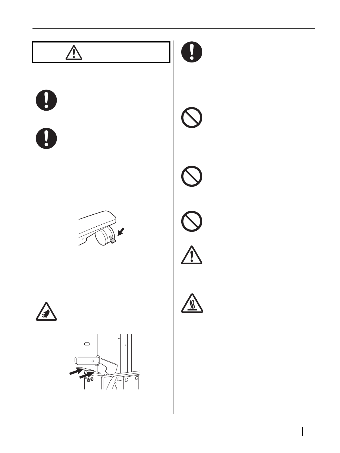
CAUTION
Locking the
casters
(Push to lock)
When the stand is to be moved, get
another person to help you and move it
together.
Otherwise, it may cause injury.
Lock the casters (when using the stand)
both afte r instal lation has be en complet ed
and after the stand has been moved.
If the stand is used with the casters
unlocked, it may move or be overturned
and/or cause injury.
After completing the installation or moving
the stand to another location, be
absolutely sure to attach the foot
reinforcing assemblies to prevent the
stand from toppling.
For Your Safety
When items are to be placed on the table
plate, put them toward the rear of the
board.
Otherwise, they may be sandwiched
between the table plate and elite
Panaboard while the board is moving up
or down, and this may damage the
system.
Do not allow children to play near the elite
Panaboard, stand on it or crawl under it.
Children may become sandwiched
between the elite Panaboard and the
table plate when the board is moving
down or they may overturn the stand
accidentally.
Do not allow children to hang or swing
from the projector or arm.
The system may be overturned or
damaged and/or the children may be
injured.
Operating Safeguards
Take care to prevent your fingers from
being pinched while the elite Panaboard
is moving up or down.
Otherwise, it may cause injury.
Do not trip over the stand’s feet.
Otherwise, it may cause injury.
Take care not to bang your head against
the projector.
This is an ov erhead projector so you m ay
bang your head against it depending on
the height of the up/down part.
Be careful around the projector ventilation
area, which becomes hot.
Working in this area or touching nearby
objects may cause injury.
5Operating Instructio ns
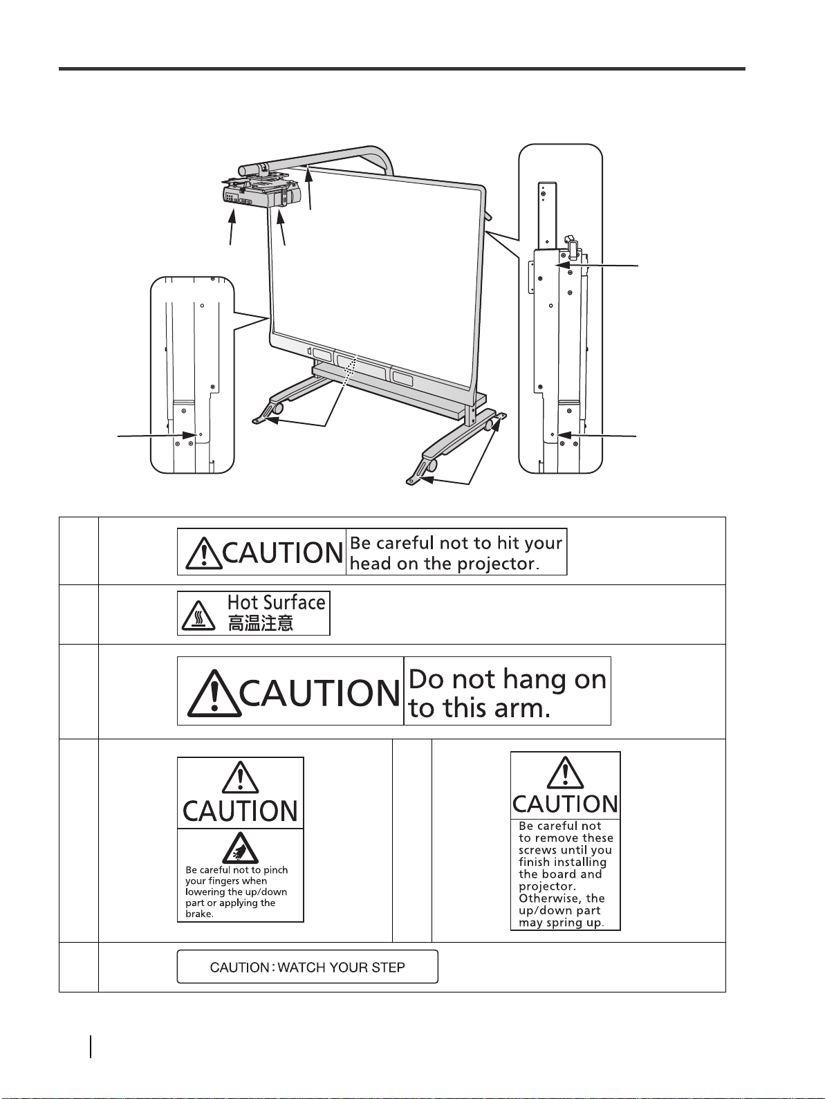
For Your Safety
Side View
Side View
Warning Label
!3"
!1"
!2"
!5"
!1"
!2"
!6"
!4"
!5"
!6"
!3"
!4"
!6"
6 Operating Instructions
!5"
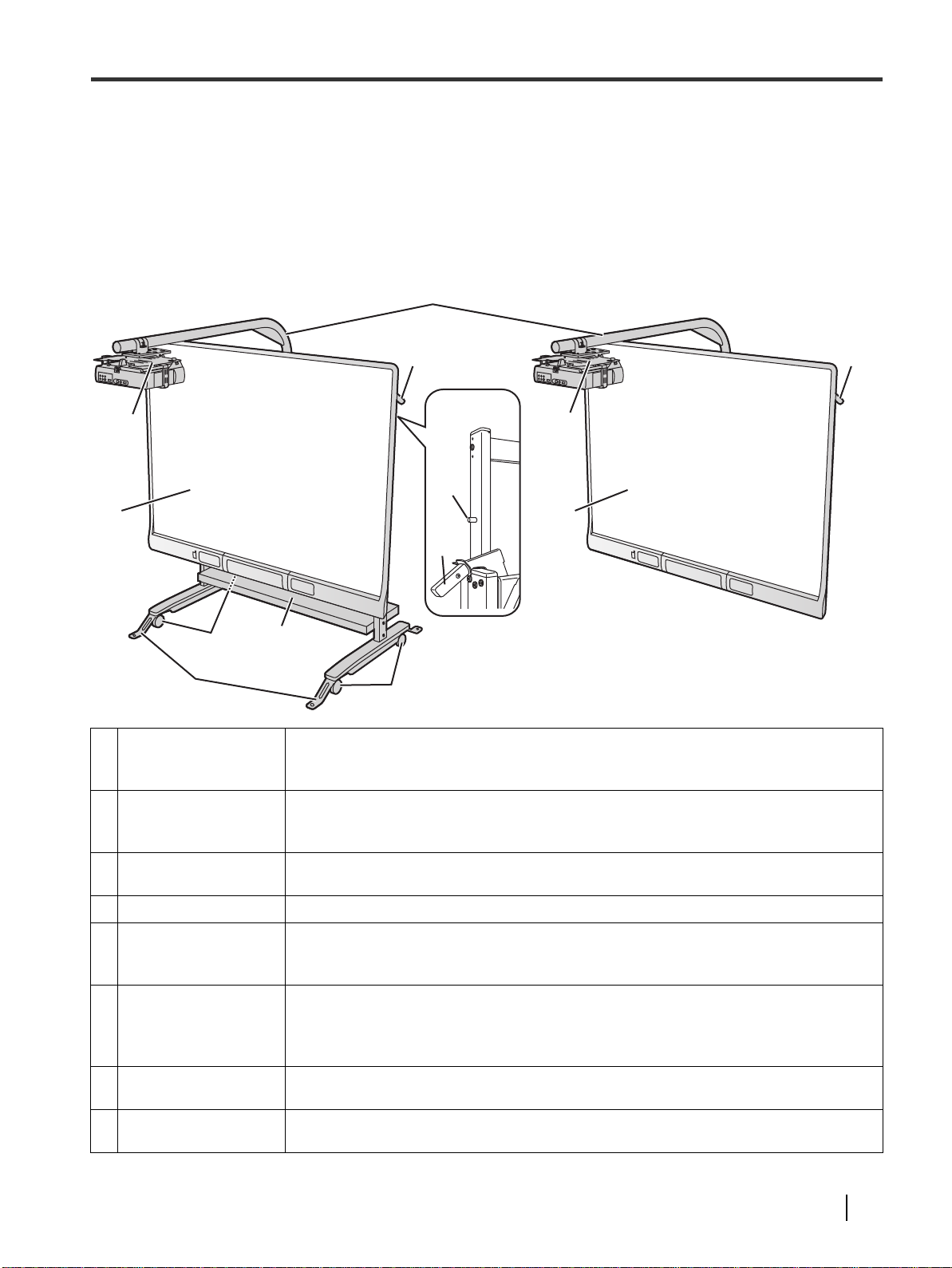
Usage
Rear View
Included Accessories
Check that the following item is included with your up/down wall kit or up/down stand kit.
• Operating Instructions- - -1
Names and Uses of the Parts
∫ When using with the stand ∫ When mounting onto a wall
!1"
!4" !4"
Usage
!2"
!7"
!6"
!1"
Projector Arm
!2"
Projector Bracket
!3"
elite Panaboard
Safety Brake
!4"
!5"
Pin End Stoppers
Foot Reinforcing
Assemblies (Only
!6"
when the stand is
used)
Casters (Only when
!7"
the stand is used)
T able Plate (Only when
!8"
the stand is used)
!2"
!5"
!3"!3"
!4"
!8"
!7"
The projector is mounted on this pipe which, when the elite Panaboard is moved
using the stand, can be turned clockwise or counterclockwise until the arm is made
parallel with the screen.
This is used to mount the projectors made by several companies. The actual
projector mounting is carried out by the service engineer so consult the engineer
concerning the mounting of the projector.
The elite Panaboard can be installed on the stand or on the wall.
(model UB-T780, UB-T781, UB-T781W, UB-T880 or UB-T880W)
This can be applied to ensure that the elite Panaboard will not move up o r d ow n.
These are put in to place at so me point along the up/dow n moving ra nge to en sure that the
projector will not sud den ly dro p dow n to a low er po sition. Be fore low e ring t he proje ctor to
its lowest position and, w ith the pin end stoppe rs push ed in , lower the up /dow n frame .
When using the system with the stand, make sure that the foot reinforcing
assemblies are installed to prevent the system from toppling over. Before moving
the stand, be absolutely sure to remove the foot reinforcing assemblies from the
stand base.
Further movement of the stand can be prevented by locking the rear casters.
The equipment (such as a notebook computer) to be used along with the elite
Panaboard can be placed on the table plate.
7Operating Instructio ns
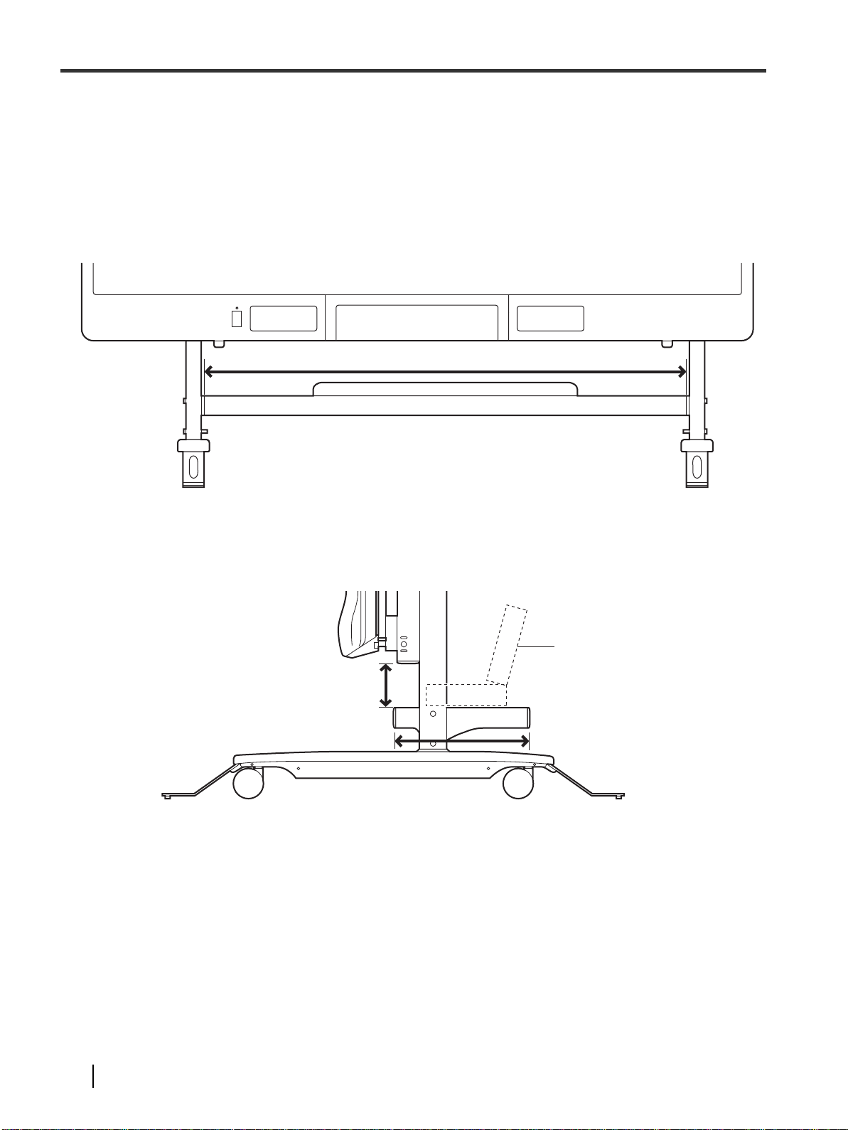
Usage
Stand Part (Front)
1,150 mm (3 ft. 99/32 in.)
Stand Part (Side)
110 mm (411/32 in.)
350 mm (1 ft. 1
25
/32 in.)
Notebook Computer
Checkpoints When Installing the Equipment on the
Table Plate
There are limits on the dimensions of the equipment which can be placed on the table plate so check them out.
8 Operating Instructions

Usage
Locking the casters
(Push to lock)
Safety Brake
Securing the Stand
Once you are satisfie d w it h whe re t he stand has been
installed, lock the cas ter s and se cure the stand prior to
use.
Moving the el ite
Panaboard Up or Down
Take hold of the board side frame or board bottom,
and move the elite Panaboard or down. (The figure
provided here shows the elite Panaboard and projector
being used with the stand.)
Note
• The preceding height is the height of the elite
Panaboard unit . (N ot inclu din g t he heigh t of the
projector arm.)
• The screen of models UB-T 880 and UB-T880W serve s
as a touch sensor. Avoid touching the scr een sur fa ce
when raising or lowering the board, beca use your
finger will be de tected a nd th e c ursor or e lect roni c p en
position (where the screen was touched previ ously) will
move to position you touch.
Once you have decided on the height at which the
elite Panaboard is to be used, pul l the saf ety b rake
lever down to secure the board in place.
• Adjustable ra nge o f he ig ht
Highest point: 2,120 mm (6 ft. 11
Point at which the elite Panaboard is stopped by the
first pin end stopper: 1,865 mm (6 ft. 1
Lowest point: 1, 67 0mm (5 ft . 5
(Usually, the elite Panaboard is used at a height
between the highest point and the point at which it is
stopped by the pin end stopper.)
15
3
/4 in.)
/32 in.)
7
/16 in.)
9Operating Instructio ns

Usage
Pin End Stopper
(Safety Brake Side)
Safety Brake
A
The pin end stoppers are provided at points along the
450 mm (1 ft. 5
points in the range from the highest point and at the
point where the elite Panaboard will be stopped by the
stoppers. When the system is to be moved, release
the safety brake (1) and simultaneously push one pin
end stopper (the one on the safety brake side) (2) and
lower the elite Panaboard slightly. Then
simultaneously push the other pin end stopper and
lower the elite Panaboard to the lowest point.
lowering the elite Panaboard to the lowest point, pull
the safety brake lever to secure the board.
23
/32 in.) adjustment range. Use them at
After
Using the elite Panaboard
1 Turn on the power of the computer and
projector.
2 When an image has appeared on the screen of
the elite Panaboard, adjust the projector. (Refer
to “Adjusting the Screen Image” (page 10).)
3 Turn on the power of the elite Panaboard.
4 Proceed with calibration.
(Refer to the Operating Instructions of the elite
Panaboard unit.)
Adjusting the Screen
Image
If the desktop screen image displayed has trapezoidal
distortion or if it is out of focus, adjust the projector,
and optimize the image.
Notice
• When pushing the pin end stoppers and then moving
the elite Panaboard down to an even lower position,
remember that the projector will also be lowered at
the same time. Take c are to preven t the p rojec tor fro m
hitting your head or other parts of your body.
• Similarly, the up/down part on which the elite
Panaboard is installed will also move down to a low
position so exer ci se car e whe n tall equipment has
been placed on the table plate.
• Be careful to avoid pinching your finger in the pin end
stopper hole.
Note
• If projected images are distorted because the
projector lens has become deformed, it may not be
possible to align the position touched on the screen
with the display po siti on ev en by pe r for mi ng
calibration.
10 Operating Instructions
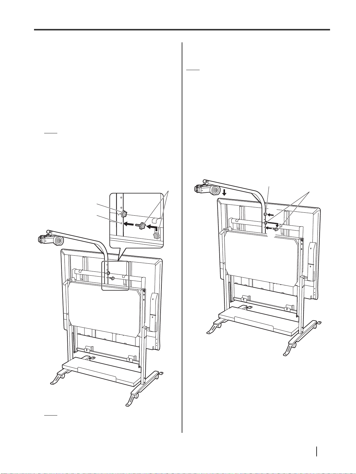
Usage
Knob B
Knob A
Hole for Securing
Projector Arm
Knob B
Knob A
Moving the Stand
Stowing the Projector Assembly
Prepare to move the stand by carrying out the steps below.
1
Disconnect the power cable from the power outlet.
2 Move the projector.
•
While lifting the projector arm slightly, turn it clockwise
or counterclockwise slowly, and move the arm so that
it is made parallel with the elite Panaboard unit.
Note
• At the lowest point, the projector may come into
contact with the unit. Rotate the arm away, so
that the projector will not touch the unit.
3 Attach knob B (with the board bracket
attached) at the position shown in the figure
and secure the projector arm.
4 Lower the elite Panaboard to the lowest point.
Note
• If the height of the entrance is less than 2 m
(6 ft. 6
having moved the projector, lower the height of the
projector arm by following the steps below.
1
2
3
4
3
/4 in.), proceed with steps 1 and 2, and after
Attach knob B to the top hole.
Lift the projector arm slightly and remove knob A
from the projector arm.
(The position of knob A varies depending on the
projector used.)
Lower the projector arm to the position where
knob B stops it.
Attach removed knob A to the securing position,
and secure the projector arm.
Note
• The position of knob A varies depending on the
projector used.
11Operating Instructions

Usage
Foot Reinforcing Assembly
Release Levers
Removing the Foot Reinforcing
Assemblies
While grasping the release lever on the back side of
each foot reinforcing assembly, pull the assembly from
the stand base.
Notice
• Before moving the stand, be absolutely sure to
remove the foot reinforcing assemblies from the stand
base. If the stand is moved with these assemblies still
attached, it may cat ch o n sur rou nd ing ob je ct s, cau se
somebody to trip over and/or cause injury .
• In case of securing the foot reinforcing assemblies
using the bolts, please contact your dealer.
Notice
When moving the stand
• Release the lock lever for each cast er.
• Before moving the stand, disconnect the plug of the
table tap from the wall outlet.
• Make sure that none of the cables are dragged along
with the stand.
• Be absolutely sure to have another person ready to
help you move the stand.
• Take care that none of the equipment placed on the
table plate will fall off.
• While moving the stand, the stowed projector will
move out of your fi el d of vie w so wh ile mov in g th e
stand, take care not to allow the projector to bump into
a wall, door or other individuals around you.
Moving the Stand
First get somebody to help you. Then take hold of the
frame on the elite Panaboard sides and protective
cover of the stand, and move the stand together.
After the stand has been moved, follow the steps below to
return it to the condition in which it was before it was moved.
1 Lock the stand’s casters.
2 Turn the casters so that they point inwards.
3 Re-attach the foot reinforcing assemblies.
4 Return the knob currently in the hole for
securing the projector arm to the hole on the
board bracket.
• If the height of the entrance is less than 2 m
3
(6 ft. 6
(page 11) in reverse.
/4 in.), perform step 1 to 4 in the note
5 Move the projector in front of the elite
Panaboard.
6 Connect the power cord.
• Readjust the projector as needed and align it
with the screen.
12 Operating Instructions
 Loading...