

Panasonic TX-32LWD500A, TX-27LWD500A User Manual
TX-32LWD500A
TX-27LWD500A
High Definition Digital Wide Screen LCD Television
®
TM
Operating Instructions
Please read these operating instructions completely before operating this set. Retain the booklet for future
reference.
®
Trade Mark of the DVB Digital Video Broadcasting Project (1991 to 1996)
Registration number 3727 (32LWD500A), 3725 (27LWD500A)
HDMI, the HDMI logo and High-Definition Multimedia Interface are trademarks or registered
trademarks of HDMI Licensing LLC.
Trademark of the SD Card Association
TM
Dolby and the double-D symbol are trademarks of Dolby Laboratories.
Manufactured under licence from Dolby Laboratories.
Panasonic
TQB4CM039-1

Panasonic and the Environment
Dear Panasonic Customer
Thank you for choosing to buy a Panasonic colour television. This product was assembled at our Panasonic Television Factory
in Penrith, New South Wales, Australia under our Quality and Environmental Management System. You can therefore be
assured that you have purchased a quality product incorporating environmentally friendly features including low standby power
usage and lead free soldering. Our company is also continuously improving the environmental performance of our product
through the elimination of hazardous chemicals including brominated flame retardants and Chromium 6.
As part of our commitment to conserving natural resources, we recognize that product packaging can be a valuable resource
and if not disposed of properly, contributes the waste stream and or end up in landfill. As part of our commitment to conserving
natural resources we provide the following information about the reuse, recycling and disposal of your packaging.
CARDBOARD
Cardboard comprises the majority of the packaging in your Panasonic TV and all of our cartons are
manufactured with optimum levels of recycled fibre.
1. Reuse
2. Recycling
Cartons can be readily folded and packed flat for storage and made up when required for later use.
If you, or someone else has no further use for the carton, it can be flattened or cut up and placed into the recycle bin or
service provided by your local council (applicable for most parts of Australia). By recycling the cardboard you are
benefiting the environment by reducing waste to landfill and reducing the dependence on virgin forest timbers for paper
fibre.
PLASTICS
Panasonic is reducing the number of different plastics used in both the television and its packaging.
Unfortunately you are unable to include the type of plastic used in television packaging in the curbside-recycling program.
Polystyrene foam and other plastic will need to be placed in your general waste bin.
Panasonic companies world wide are committed to an environmental Policy that envisions a world where humanity co-exists with
the global environment where each company strives to realize this vision by continuing to minimise the environmental impacts of
all business operations and offering products and services that further improve the quality of life. Please visit the Panasonic
group website on http://panasonic.co.jp/global/
contribute funding to support the curbside recycling of packaging and the recycling of colour television receivers.
Panasonic Australia Pty Limited and Panasonic AVC Networks Australia Pty Ltd are active participants in CESA (Consumer
Electronics Supplier Association). This group is currently working on how to manage end-of-life disposal of manufactured
products in an environmentally responsible manner and are collaborating with government, industry and other stakeholders in
striving for best practice in Product Stewardship.
Panasonic Australia Pty Limited and Panasonic AVC Networks Australia Pty Ltd are signatories to the
‘National Packaging Covenant’. The covenant is an agreement between governments and member
companies aimed at reducing the amount of waste going to landfill through REDUCING, REUSING and
RECYCLING.
Panasonic Australia Pty Limited and Panasonic AVC Networks Australia Pty Ltd have Environmental
Management Systems in place. Both companies are committed to reducing, reusing and recycling and
REDUCE ~ REUSE ~ RECYCLE
ABOUT PANASONIC
2
Important Information
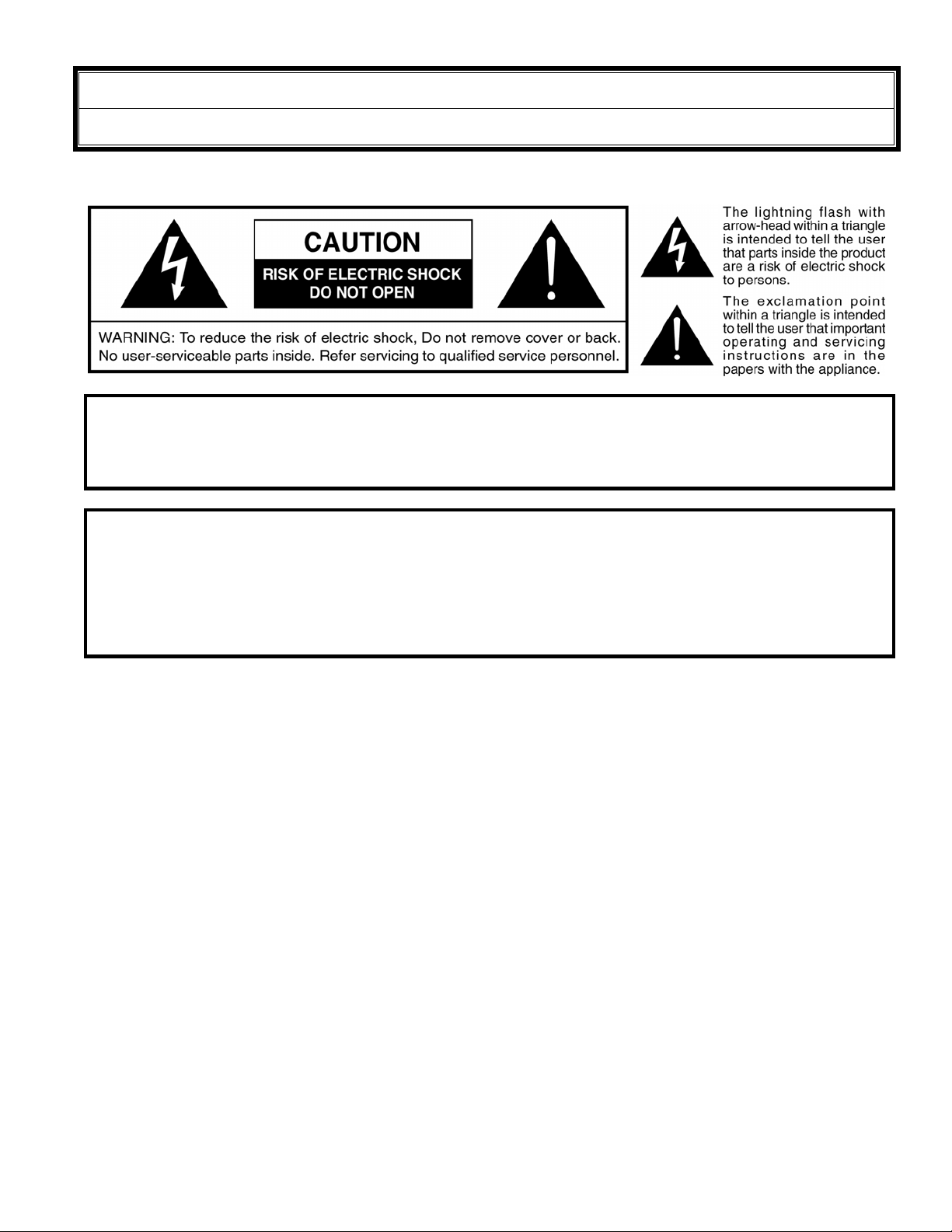
Warning
WARNING: To reduce the risk of fire or electric shock, do not expose this apparatus to rain or moisture. Do not
place liquid containers (flower vase, cups, cosmetics, etc.) above the set (including on shelves above,
etc.).
WARNING: 1) To prevent electric shock, do not remove cover. No user serviceable parts inside. Refer servicing to
qualified service personnel.
2) Do not remove the grounding pin on the power plug. This apparatus is equipped with a three pin
grounding-type power plug. This plug will only fit a grounding-type power outlet. This is a safety feature.
If you are unable to insert the plug into the outlet, contact an electrician.
Do not defeat the purpose of the grounding plug.
This television is heavy (please see page 31). Although the television has been tilt tested and meets current
Australian and International Standards, we recommend that great care be taken when positioning the television.
* Do not allow the front of the set to overhang the stand or cabinet.
* Do not allow anyone to climb or sit on the television.
* Do not place any heavy weights on the television.
* Do not block any ventilation openings. Install in accordance with this instruction manual.
* Apparatus shall not be exposed to dripping or splashing and no objects filled with liquids, such as vases, shall
be placed on the apparatus.
* To reduce the risk of electric shock, do not remove cover (or back). No user-serviceable parts inside. Refer
servicing to qualified service personal.
* The apparatus must be connected to a mains socket outlet with a protected earthing connection.
* Keep 10cm minimum distance around the apparatus for sufficient ventilation.
3

Analogue and Digital television - what are they?
Analogue transmission is the system that has been used for many years for broadcasting television programmes.
With continuous improvements in technology it is now possible to transmit programmes in a digital format, allowing
clearer pictures, more stations and other services to be displayed on screen. Digital television is provided in three
different ways; it can be sent along a cable connection direct to your house, broadcast from a satellite, or broadcast
using traditional land based (terrestrial) transmitters. The first two options require you to have an extra 'set top box'
decoder and in the case of satellite, a receiving dish mounted outdoors.
While allowing you to receive traditional analogue transmissions in the usual way, this television can also receive
terrestrial digital services using an integrated (Digital Video Broadcasting) decoder. This allows you to enjoy the
new era of digital terrestrial television without the need for a 'set top box' or satellite dish - a good quality roof
mounted antenna should be all you need.
Customer’s Record
The serial number of this product can be found on its rear cover and on the carton. It is recommended that you note
the serial number and other details in the space provided and retain this booklet in a safe place as a permanent
record of your purchase to aid in identification in the event of theft or loss.
Model No.
Serial No.
Purchase Date
Purchased From
Pixel Statement (LCD)
An image on an LCD panel is created by many dots known as pixels. The more pixels on the panel, the more
detailed image can be displayed. To create a colour image each pixel is made up of three tiny coloured dots (1 each
of red, green and blue). This gives a total far in excess of one million individual dots manufactured into the panel.
Each one of these dots is precisely controlled by the electronics of the TV to produce the picture.
Whilst Panasonic maintains the highest standards in manufacturing technology and processes in the construction of
these panels, there are a number of allowable Pixel/Dot failures that would still allow the panel to be defined as a
good panel. It is not possible to guarantee absolutely no pixel loss.
4

Contents
Getting Started..............................................................................................................................................6 ~ 12
Battery Installation and Replacement ............................................................................................6
Battery Precautions........................................................................................................................6
Using the LCD stand......................................................................................................................6
Connectors.....................................................................................................................................6
Connecting the Antenna ................................................................................................................7
Connecting DVD Players and VCRs etc........................................................................................7
Which connectors to use................................................................................................................8
Connecting Component Video equipment .....................................................................................8
Connecting Video equipment.........................................................................................................8
Turn on the television.....................................................................................................................9
Front Panel Controls ......................................................................................................................9
Remote Control Buttons...............................................................................................................10
Auto Setup ...................................................................................................................................11
Using the On-Screen Displays.....................................................................................................11
Picture Menu .....................................................................................................................................................12
Sound Menu .....................................................................................................................................................13
Setup Menu .....................................................................................................................................................14
DVB System Setup .....................................................................................................................................15
Favourites Setup.................................................................................................................................................16
DVB Tuning Menu...............................................................................................................................................17
Shipping Condition.............................................................................................................................................18
Analogue tuning menu.......................................................................................................................................19
Special buttons ...........................................................................................................................................20 ~ 22
Information ...................................................................................................................................20
Coloured Buttons (for AV Selection)............................................................................................20
Guide............................................................................................................................................21
Aspect .........................................................................................................................................22
Multi Window................................................................................................................................22
Audio ............................................................................................................................................22
Teletext Operation ..............................................................................................................................................23
Card Reader .............................................................................................................................................24 ~ 25
Setup............................................................................................................................................24
Slideshow Setup ..........................................................................................................................25
Preferences Setup .......................................................................................................................25
Other Connections .............................................................................................................................................26
Headphones.................................................................................................................................26
Front AV Connections..................................................................................................................26
HDMI input ...................................................................................................................................26
VCR Out .....................................................................................................................................26
Monitor Out and Audio Out ..........................................................................................................26
Customer Information ................................................................................................................................27 ~ 31
Warnings and Cautions................................................................................................................27
Frequently Asked Question..........................................................................................................28
Troubleshooting ...........................................................................................................................29
Specifications ...............................................................................................................................31
i
5
Getting Started
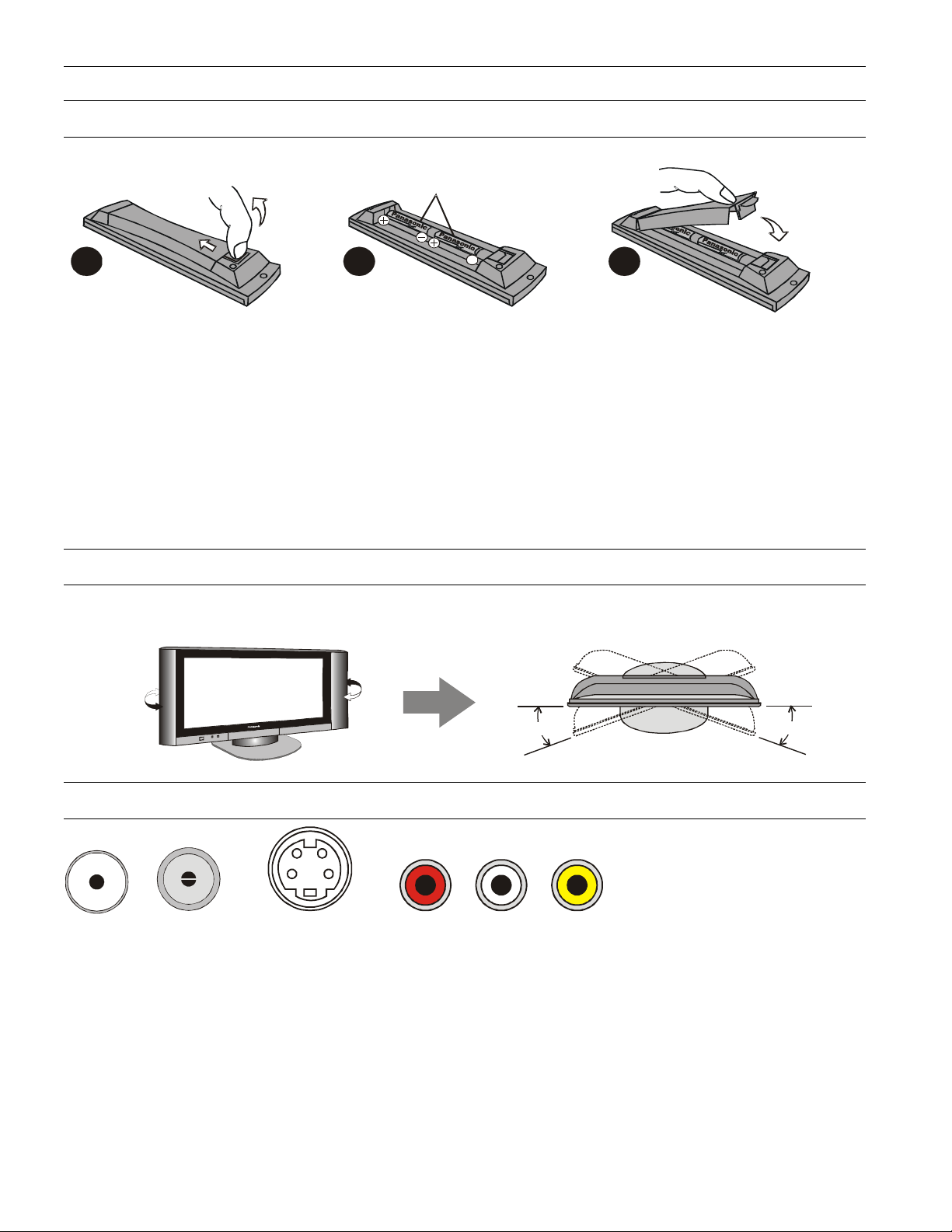
Battery Installation and Replacement
1 2
Place your fingernail under the
battery cover hook. Apply a
slight downward and backward
pressure and lift the cover off.
• Do Not use rechargeable batteries.
• Do Not mix battery types
Insert the batteries ensuring the
correct polarity.
• Do Not mix old and new batteries. Replace both
batteries at the same time.
• Do Not attempt to recharge batteries.
2 x “AA” Batteries
• Do Not short circuit batteries.
• Do Not disassemble batteries.
• Do Not heat or burn batteries.
3
Fit the battery cover and click it
into place.
Using the LCD Stand
You can adjust the angle of the LCD panel to suit. The panel can swivel 15° left or right.
15°
Connectors
F and RF connectors are used for
connecting antenna leads.
The S-VIDEO connector is used for
Video only.
RFF S-VIDEO RCA
RCA connectors are used for video and audio connections.
Audio Video
Red Right Yellow Composite video
White Left Green Component Video (Y)
Red Component Video (Pr)
Blue Component Video (Pb)
NOTE: take care not to mix the two red RCA connectors.
15°
6
Getting Started
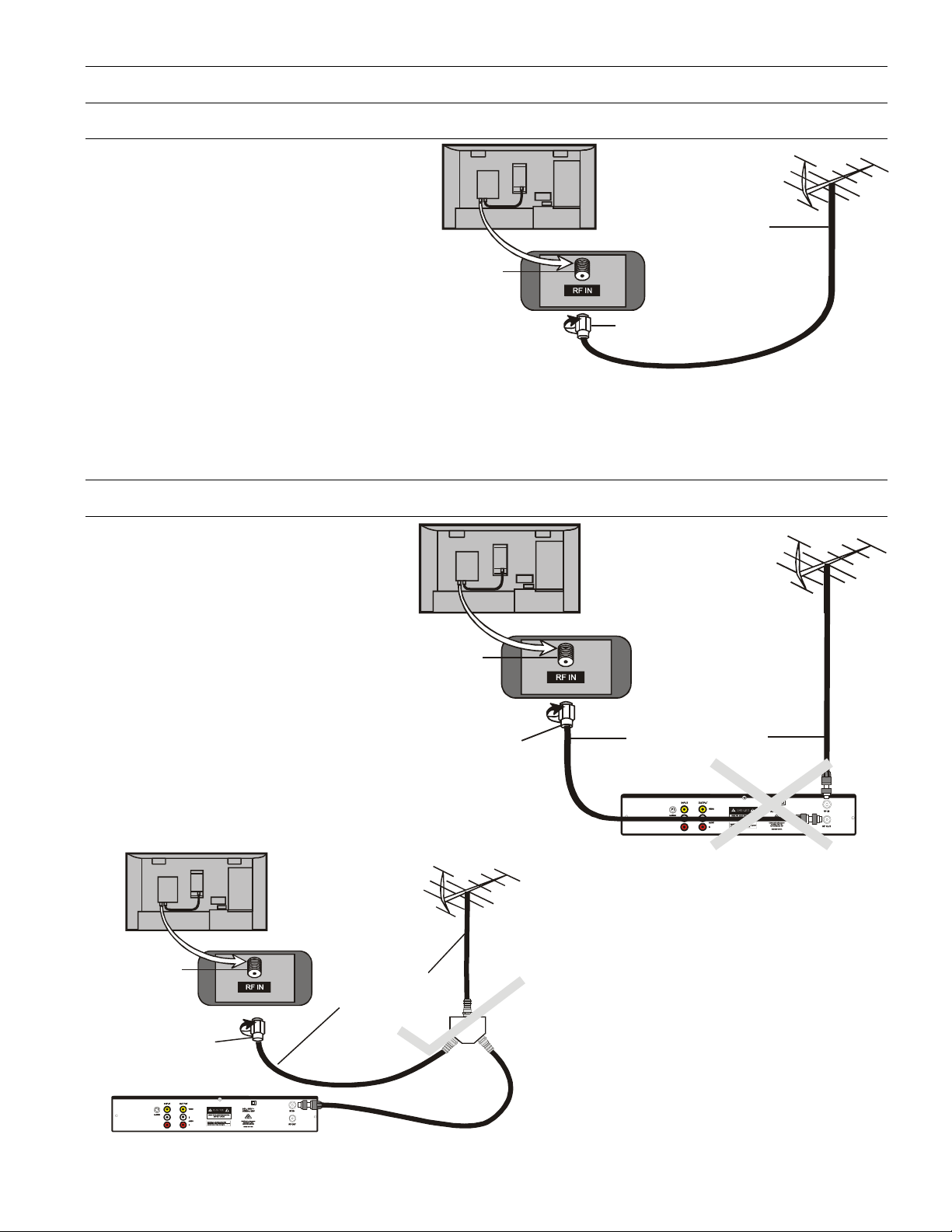
Connecting the Antenna
Connect the television to the antenna wall
plate and a good quality outside / roof
antenna. This television uses an “F”
connector for the RF input. If your wall
plate or antenna lead is the standard
“Belling Lee” connector, use the supplied
“F” to “Belling Lee” adaptor.
Plug the “F” connector firmly into the TV
antenna input and then lock it in place with
the locking nut.
NOTE: Turn the nut only, do not turn the cable.
For your safety any external antenna should be installed by a reputable qualified installer and should comply with
Australian Standard AS1417.1. The RF (Antenna) Input impedance of this television is 75Ω.
Antenna Terminal
75Ohm Coaxial Cable
(RG59 Quad Shield)
“F” Type Connector
Connecting DVD players and VCRs etc
For optimal Digital TV reception, use
an antenna splitter (bottom page
illustration) when also connecting a
VCR / DVD Recorder to the digital TV.
Traditionally, with analogue TV, you will
have connected the antenna to the
VCR and then connected the VCR to
the TV. If your signal strength is
sufficient, this method can be used.
Note: It might require that the VCR or
DVD recorder has to be turned on to
ensure that the signal passes through
to the television.
Antenna Terminal
“F” Type Connector
VCR / DVD Recorder etc.
Antenna Terminal
“F” Type Connector
75Ohm Coaxial Cable
(RG59 Quad Shield)
Splitter
75Ohm Coaxial Cable
(RG59 Quad Shield)
VCR / DVD Recorder etc.
We recommend that you use a splitter to connect
the antenna to the TV and to the VCR etc. This
should ensure that signal loss is reduced as much
as possible.
7

Getting Started
A
A
A
A
A
A
A
A
A
A
Which connectors to use
First you must determine what video input connectors you have on your television. You might have:
1. Component Video (YPbPr) - represented by Red, Green and Blue RCA connectors. This connection will
produce the best picture.
2. S-Video - represented by the S-Video connector. This produces the next best picture.
3. Composite Video (CVBS) - represented by a single Yellow RCA connector.
Connecting Component Video Equipment
Component Video (also called YPbPr, DVD,
YUV or YCbCr) will give the best picture.
These connectors are coloured Green (Y),
Blue (Pb) and Red (Pr). Make sure that you
match the colours when you make your
connections.
TX-32LWD500A
OUTPUT
L
AUDIO
R
Y
Pb
Pr
Note:
red leads.
Back of TV
TX-27LWD500A
Take care not to swap the two
L (White )
R (Red)
Y (Green)
Pb (Blue)
Pr (Red)
V
V
VIDEO
VIDEO
L
L
UDIO
UDIO
R
R
G
Y
V
B
Pb
L
UDIO
R
Pr
R
TX-32LWD 500A TX-27LWD50 0A
PC AUDIO IN
Pr
Y
Pb
UDIO INPUT
R
L
VGA
R
L
UDIO
G
R
B
V
Connecting Video Equipment
Connect the antenna to the TV and the
VCR as shown on page 7.
Connect the equipment using either the SVideo connector (preferred) or the
Composite video (Yellow) cable.
TX-32LWD500A
S-Video equipment uses a 4Pin Mini Din
(Male) plug for the video and RCA plugs
S-Video
VIDEO
AUDIO
OUTPUT
L
R
for the audio.
Most standard Videocassette Recorders
use RCA type video and audio connectors.
The connectors are:
Yellow: Video
Red Right Audio
White Left Audio
Notes:
1. If you cannot use Component video connections then S-Video is the next best choice.
2. When an S-Video cable is connected to an S-Video input terminal, the RCA video terminal for that AV position
will be disconnected.
3. The Audio and Video cables are not supplied with this television.
4. If your equipment has different type connectors please refer to the manufacturer’s instruction book for details.
Back of TV
TX-27LWD500A
S-Video
V (Yellow)
L (White)
R (Red)
V
VIDEO
L
UDIO
R
VY
L
UDIO
R
TX-32LWD500A
VIDEO
Pb
V
VIDEO
L
UDIO
G
B
R
R
V
VIDEO
L
UDIO
R
TX-27 LWD500A
V
L
UDIO
R
Pr
8
Getting Started
Turn on the television
Push the Power Switch to turn the
television ON.
Notes:
1. The TV takes approximately 10 seconds to turn ON. Like your computer, it has to run a number of diagnostic
and software checks before it can display any broadcast channels.
2. The indicator will be red when the television is in Standby, green when the TV is operating and off when the
TV is unplugged.
3. The indicator will flash when a valid code is received from the remote control when a button is pressed.
4. If the television is not going to be used for an extended period, remove the power plug from the wall outlet.
Panasonic
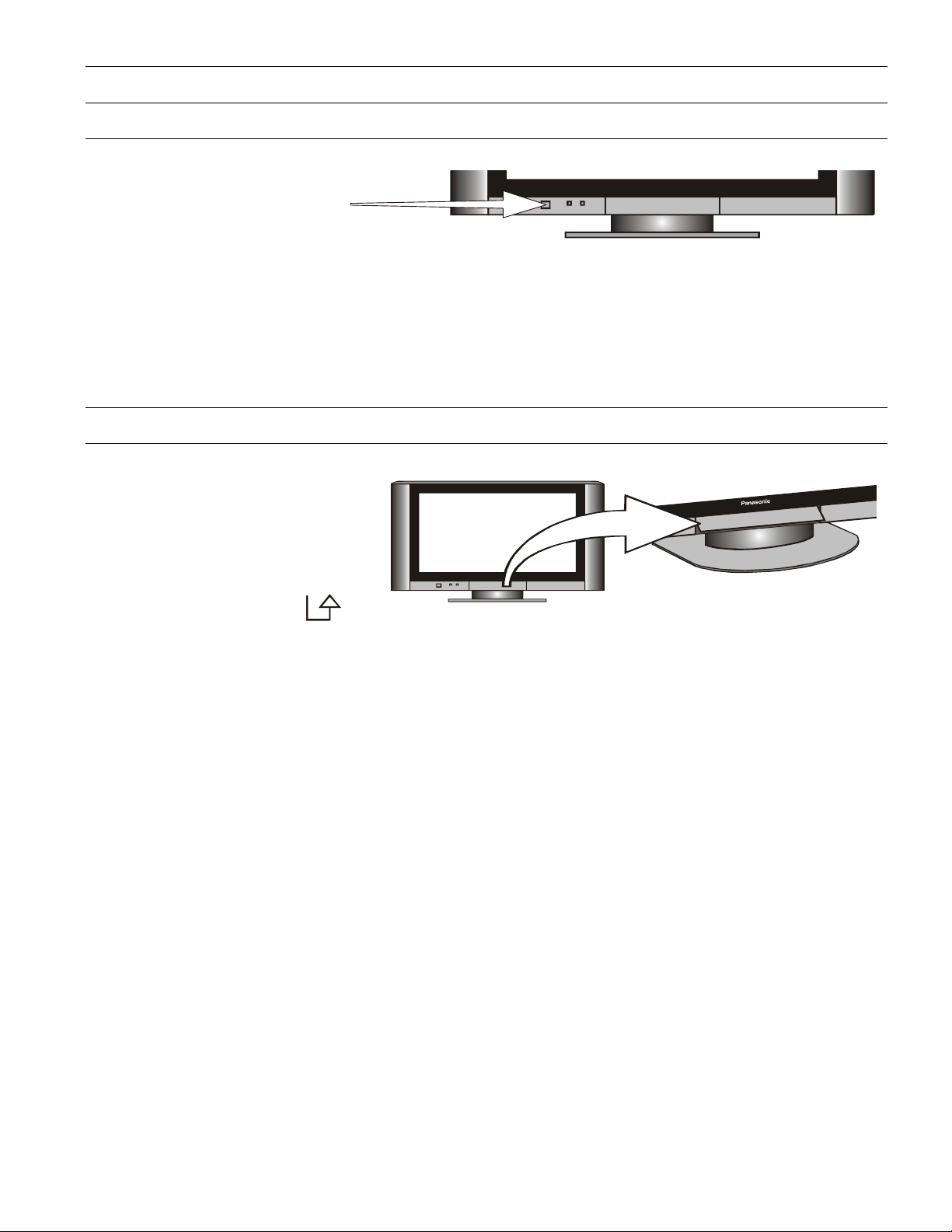
Front Panel Controls
Push the Power Switch to turn the
television ON. Unless your dealer has
already programmed your television then
Auto Setup will begin Please refer to
page 11.
Open the front panel door to gain access
to the Television Controls.
Lift the door at the symbol on
the bottom right hand corner.
TV / AV
MENU
< VOLUME >
\/ CHANNEL /\
Notes:
1. When the television is in Stand-By it is possible to turn it back on by pressing the POWER Button on the front
panel.
2. This television is designed for the Australian Standard Mains Voltage of 240V 50Hz.
This button is used to select the input to be displayed on the screen. Pressing the button shows
in turn: DVB, Analogue, AV1, AV2, AV3, AV4, HDMI, PC and back to DVB.
This button displays the main menu. From this menu you can select the Picture, Sound and
Setup menus. See pages12, 13 and 14.
These buttons are used to turn audio volume lower or higher.
If user menu is displayed these buttons are used to access or adjust user menu options.
These buttons are used to select the next lower / higher programme number.
If user menu is displayed these buttons are used to move up or down to select user menu
options.
Panasonic
9

Getting Started
Remote Control Buttons
Standby Switches TV on or off (standby).
SD Switches the SD Card reader on or off.
Mode Switches between viewing DVB and Analogue modes.
Guide Displays the DVB Guide (see page 21).
TV/AV Switches between viewing TV or AV input.
Cursor Used to make selections and adjustments.
OK Used to confirm selections and choices.
Menu Press to access the Picture, Sound and Setup menus
Exit Used to exit the menu system.
Coloured buttons Used for the selection, navigation and operation of various
functions. (See page 20 for AV selection)
TV/ Text Switches between TV and Teletext modes
STTL Displays subtitles if available (see page 23).
Index Selects the teletext index page.
Hold Freezes the Teletext page. Press again to return to normal.
N (Normalise). Will recall stored settings.
Mute Switches the sound mute on or off.
Channel up/down (/\ \/) Selects the next higher or lower channel.
Volume up/down (+ -) Increases or decreases the volume.
Numeric buttons Used for: - Programme / channel change.
C (Direct channel access) - During analogue TV viewing or when in the
Tuning menu, press and then enter channel number using the numeric
buttons. (Press again for special channels).
(Information) - Shows status information for the current Programme
i
Aspect Changes the aspect ratio of the TV (see page 22).
Ambience Turns the “Surround Sound” on or off.
MULTI WINDOW (see page 22)
AUDIO (see page 22).
The Remote Control is capable of operating some functions of selected Panasonic VCRs and DVD (Digital Versatile
Disc) equipment. Some VCR and DVD equipment have different functions, so to ensure compatibility please refer to
the equipment's instruction book or consult your dealer for details.
Record Press this button to start recording
Standby Switches the VCR or DVD player on or off (standby).
VCR/DVD Switch The position of this switch selects whether the remote control operates a VCR or DVD
player.
Programme up/down Selects the next higher or lower channel on the VCR.
Skip / Fast Forward / VCR: Press to fast forward the tape. In Play mode,
Cue press to view the picture rapidly forward.
DVD: Press once to skip to next track. Press and hold to view
the picture rapidly forward.
Skip / Rewind / Review VCR: Press to rewind the tape. In Play mode, press to view the
picture rapidly backwards.
DVD: Press once to skip to next track. Press and hold to view
the picture rapidly forward.
Stop Press to stop the tape or DVD.
Pause/Still Press in Play mode, the picture will pause. Press again to restart.
Play Press to start the VCR or DVD playing.
position.
10
 Loading...