

Page 1
English
For more detailed instructions, refer to the
Operating Instructions on the CD-ROM.
Operating Instructions
FULL HD LCD Display For business use
Model No.
TH-42LF8W
TH-49LF8W
TH-55LF8W
TH-42LF80W
TH-49LF80W
TH-55LF80W
Contents
Important Safety Notice ···························· 2
Safety Precautions ·································· 4
Precautions for use ·································6
Accessories ··········································· 9
Connections ·········································11
Identifying Controls ······························· 14
Basic Controls ······································ 16
Specifications ······································ 18
Software License ·································· 21
42-inch model
49-inch model
55-inch model
42-inch model
49-inch model
55-inch model
Please read these instructions before operating your set and retain them
•
for future reference.
Illustrations and screens in this Operating Instructions are images for
•
illustration purposes, and may be different from the actual ones.
Descriptive illustrations in this Operating Instructions are created mainly
•
based on the 55-inch model.
TQBJ0934
Page 2
Note:
Image retention may occur. If you display a still
picture for an extended period, the image might
remain on the screen. However, it will disappear when
a general moving picture is displayed for a while.
Trademark Credits
Microsoft, Windows, Windows Vista and Internet
•
Explorer are the registered trademarks or trademarks
of Microsoft Corporation in the United States and/or
other countries.
Macintosh, Mac, Mac OS, OS X and Safari are the
•
trademarks of Apple Inc. registered in the United
States and other countries.
PJLink is a registered or pending trademark in Japan,
•
the United States, and other countries and regions.
HDMI, the HDMI Logo, and High-Definition
•
Multimedia Interface are trademarks or registered
trademarks of HDMI Licensing LLC in the United
States and other countries.
JavaScript is a registered trademark or a trademark of
•
Oracle Corporation and its subsidiary and associated
companies in the United States and/or other
countries.
RoomView, Crestron RoomView and Fusion RV are
•
registered trademarks of Crestron Electronics, Inc.
Crestron Connected is the trademark of Crestron
Electronics, Inc.
Even if no special notation has been made of company
or product trademarks, these trademarks have been fully
respected.
Important Safety
Notice
WARNING
1) To prevent damage which may result in fire or
shock hazard, do not expose this appliance to
dripping or splashing.
Do not place containers with water (flower vase,
cups, cosmetics, etc.) above the set. (including on
shelves above, etc.)
No naked flame sources, such as lighted candles,
should be placed on / above the set.
2) To prevent electric shock, do not remove cover. No
user serviceable parts inside. Refer servicing to
qualified service personnel.
3) Do not remove the earthing pin on the power
plug. This apparatus is equipped with a three pin
earthing-type power plug. This plug will only fit an
earthing-type power outlet. This is a safety feature.
If you are unable to insert the plug into the outlet,
contact an electrician.
Do not defeat the purpose of the earthing plug.
4) To prevent electric shock, ensure the earthing pin
on the AC cord power plug is securely connected.
CAUTION
This appliance is intended for use in environments
which are relatively free of electromagnetic fields.
Using this appliance near sources of strong
electromagnetic fields or where electrical noise may
overlap with the input signals could cause the picture
and sound to wobble or cause interference such as
noise to appear.
To avoid the possibility of harm to this appliance, keep
it away from sources of strong electromagnetic fields.
English
2
Page 3
IMPORTANT INFORMATION
If a display is not positioned in a sufficiently stable
location, it can be potentially hazardous due to falling.
Many injuries, particularly to children, can be avoided
by taking simple precautions such as:
Using cabinets or stands recommended by the
•
manufacturer of the display.
Only using furniture that can safely support the
•
display.
Ensuring the display is not overhanging the edge
•
of the supporting furniture.
Not placing the display on tall furniture (for
•
example, cupboards or bookcases) without
anchoring both the furniture and the display to a
suitable support.
Not standing the displays on cloth or other
•
materials placed between the display and
supporting furniture.
Educating children about the dangers of climbing
•
on furniture to reach the display or its controls.
IMPORTANT: THE MOULDED PLUG
FOR YOUR SAFETY, PLEASE READ THE
FOLLOWING TEXT CAREFULLY.
This display is supplied with a moulded three pin
mains plug for your safety and convenience. A 10
amp fuse is fitted in this plug. Shall the fuse need to
be replaced, please ensure that the replacement fuse
has a rating of 10 amps and that it is approved by
ASTA or BSI to BS1362.
Check for the ASTA mark or the BSI mark on
the body of the fuse.
If the plug contains a removable fuse cover, you must
ensure that it is refitted when the fuse is replaced.
If you lose the fuse cover the plug must not be used
until a replacement cover is obtained.
A replacement fuse cover can be purchased from
your local Panasonic dealer.
Do not cut off the mains plug.
Do not use any other type of mains lead except the
one supplied with this display.
The supplied mains lead and moulded plug are
designed to be used with this display to avoid
interference and for your safety.
If the socket outlet in your home is not suitable, get it
changed by a qualified electrician.
If the plug or mains lead becomes damaged,
purchase a replacement from an authorized dealer.
WARNING : — THIS DISPLAY MUST BE EARTHED.
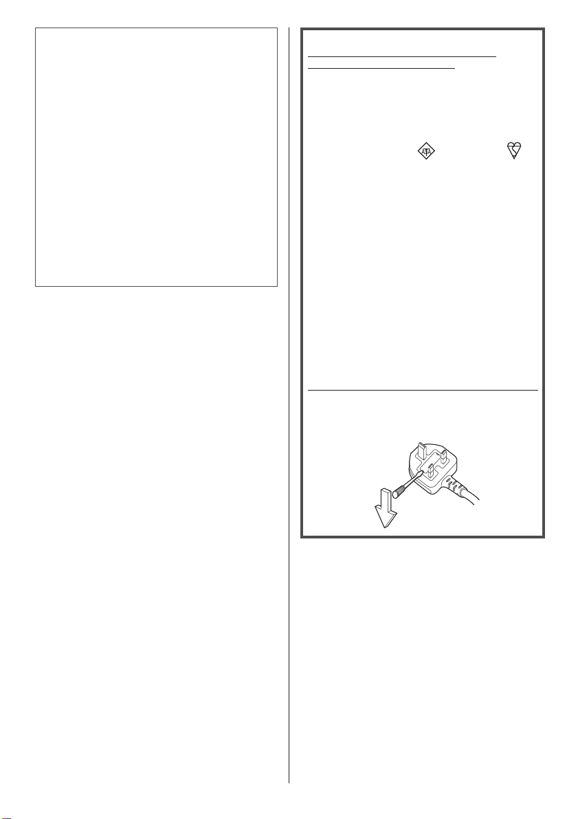
How to replace the fuse.
Open the fuse compartment with a screwdriver and
replace the fuse.
English
3
Page 4
Safety Precautions
WARNING
■ Setup
This LCD Display is for use only with the following
optional accessories.
Use with any other type of optional accessories may
cause instability which could result in the possibility
of injury.
(All of the following accessories are manufactured by
Panasonic Corporation.)
Pedestal
•
TY-ST43PE8
Digital Interface Box
•
ET-YFB100G
DIGITAL LINK Switcher
•
ET-YFB200G
Early Warning Software
•
ET-SWA100 series
Video Wall Manager
•
TY-VUK10
1: Suffix of the part number may differ depending on
*
the license type.
2: Supports Ver1.1 or later.
*
Note
●
The part number of the optional accessories are
subject to change without notice.
We are not responsible for any product damage, etc.
caused by failures in the installation environment for
the pedestal or wall-hanging bracket even during the
warranty period.
Always be sure to ask a qualified technician to carry out
set-up.
Small parts can present choking hazard if accidentally
swallowed. Keep small parts away from young children.
Discard unneeded small parts and other objects,
including packaging materials and plastic bags/sheets to
prevent them from being played with by young children,
creating the potential risk of suffocation.
Do not place the Display on sloped or unstable
surfaces, and ensure that the Display does not hang
over the edge of the base.
The Display may fall off or tip over.
•
Install this unit at a location with minimal vibration
and which can support the weight of the unit.
Dropping or falling of the unit may cause injury or
•
malfunction.
Do not place any objects on top of the Display.
If foreign objects or water get inside the Display, a
•
short-circuit may occur which could result in fire or
electric shock. If any foreign objects get inside the
Display, please consult your local Panasonic dealer.
1
*
2
*
Transport only in upright position!
Transporting the unit with its display panel facing
•
upright or downward may cause damage to the
internal circuitry.
Ventilation should not be impeded by covering
the ventilation openings with items such as
newspapers, table cloths and curtains.
For sufficient ventilation, see page 6.
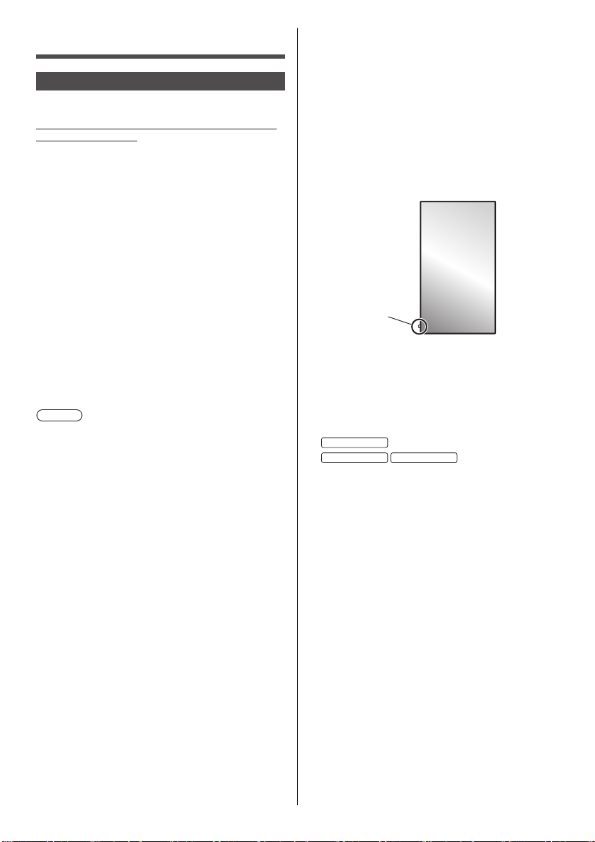
When installing the Display vertically;
When installing the Display vertically, be sure that
the Power Indicator comes to the downside. Heat is
generated and it may cause fire or damage to the
Display.
Power indicator
Cautions for Wall or Pedestal Installation
Wall or Pedestal installation should be performed
•
by an installation professional. Installing the Display
incorrectly may lead to an accident that results in
death or serious injury. Use the optional Pedestal.
When installing on a wall, a wall hanging bracket that
•
conforms to VESA standards must be used.
42-inch model
49-inch model 55-inch model
(see page 6)
If you terminate the use of the Display on the Wall or
•
Pedestal, ask a professional to remove the Display as
soon as possible.
When mounting the Display on the wall, prevent the
•
mounting screws and power cable from contacting
metal objects inside the wall. An electric shock may
occur if they contact metal objects inside the wall.
Do not install the product to a place where the
product is exposed to direct sunlight.
If the screen is exposed to direct sunlight, the liquid
•
crystal panel may have adverse effect.
: VESA 200×200
: VESA 400×400
■ When using the LCD Display
The Display is designed to operate on 220 - 240 V
AC, 50/60 Hz.
Do not cover the ventilation holes.
Doing so may cause the Display to overheat, which
•
can cause fire or damage to the Display.
Do not stick any foreign objects into the Display.
Do not insert any metal or flammable objects into the
•
ventilations holes or drop them onto the Display, as
doing so can cause fire or electric shock.
English
4
Page 5

Do not remove the cover or modify it in any way.
High voltages which can cause severe electric shocks
•
are present inside the Display. For any inspection,
adjustment and repair work, please contact your local
Panasonic dealer.
Ensure that the mains plug is easily accessible.
The mains plug shall be connected to a mains
socket outlet with a protective earthing connection.
Do not use any power supply cord other than that
provided with this unit.
Doing so may cause short-circuit, generates heat,
•
etc., which could cause electric shock or fire.
Do not use the supplied power supply cord with any
other devices.
Doing so could cause electric shock or fire.
•
Securely insert the power supply plug as far as it
will go.
If the plug is not fully inserted, heat may be generated
•
which could cause fire. If the plug is damaged or the
wall socket is loose, they shall not be used.
Do not handle the power supply plug with wet
hands.
Doing so may cause electric shocks.
•
Do not do anything that may damage the power
cable. When disconnecting the power cable, pull on
the plug body, not the cable.
Do not damage the cable, make any modifications
•
to it, place heavy objects on top of it, heat it, place it
near any hot objects, twist it, bend it excessively or
pull it. To do so may cause fire and electric shock. If
the power cable is damaged, have it repaired at your
local Panasonic dealer.
Do not remove covers and NEVER modify the
Display yourself
Do not remove the rear cover as live parts are
•
accessible when it is removed. There are no user
serviceable parts inside. (High-voltage components
may cause serious electrical shock.)
Have the Display checked, adjusted, or repaired at
•
your local Panasonic dealer.
Keep the supplied AAA/R03/UM4 batteries out of
reach of children. If accidentally swallowed, it will be
harmful to the body.
Please contact a doctor immediately in case you
•
doubt that the child may have swallowed it.
If the Display is not going to be used for any
prolonged length of time, unplug the power supply
plug from the wall outlet.
Picture noise may occur if you connect / disconnect
the connection cables of the input terminals you
are currently not watching, or if you turn the power
of the video equipment on / off, but it is not a
malfunction.
To prevent the spread of fire, keep
candles or other open flames away from
this product at all times.
CAUTION
If problems or malfunction occur, stop using
immediately.
■ If problems occur, unplug the power supply
plug.
Smoke or an abnormal odour come out from the unit.
•
No picture appears or no sound is heard,
•
occasionally.
Liquid such as water or foreign objects got inside the
•
unit.
The unit has deformed or broken parts.
•
If you continue to use the unit in this condition, it
could result in fire or electric shock.
Turn the power off immediately, unplug the power
•
supply plug from the wall outlet, and then contact the
dealer for repairs.
To cut off the power supply to this Display completely,
•
you need to unplug the power supply plug from the
wall outlet.
Repairing the unit yourself is dangerous, and shall
•
never be done.
To enable to unplug the power supply plug
•
immediately, use the wall outlet which you can reach
easily.
■ When using the LCD Display
Do not bring your hands, face or objects close to the
ventilation holes of the Display.
Heated air comes out from the ventilation holes at the
•
top of Display will be hot. Do not bring your hands or
face, or objects which cannot withstand heat, close to
this port, otherwise burns or deformation could result.
At least 2 people are required to carry or unpack
this unit.
If this is not observed, the unit may drop, resulting in
•
injury.
Be sure to disconnect all cables before moving the
Display.
If the Display is moved while some of the cables are
•
still connected, the cables may become damaged,
and fire or electric shock could result.
Disconnect the power supply plug from the wall
socket as a safety precaution before carrying out
any cleaning.
Electric shocks can result if this is not done.
•
Clean the power cable regularly to prevent it
becoming dusty.
If dust built up on the power cord plug, the resultant
•
humidity can damage the insulation, which could
result in fire. Pull the power cord plug out from the
wall outlet and wipe the mains lead with a dry cloth.
Do not step on, or hang from the display or the
Pedestal.
They might tip over, or might be broken and it may
•
result in injury. Pay special attention to the children.
English
5
Page 6
Do not reverse the polarity (+ and -) of the battery
when inserting.
Mishandling the battery may cause its explosion
•
or leakage, resulting in fire, injury or damage to
surrounding properties.
Insert the battery correctly as instructed. (see page
•
10)
Remove the batteries from the remote control
transmitter when not using for a long period of time.
The battery may leak, heat, ignite or burst, resulting in
•
fire or damage to surrounding properties.
Do not burn or breakup batteries.
Batteries must not be exposed to excessive heat such
•
as sunshine, fire or the like.
Do not turn the Display upside down.
Do not position the unit with its display panel facing
upright.
Precautions for use
Cautions when installing
Do not set up the Display outdoors.
The Display is designed for indoor use.
•
Environmental temperature to use this unit
When using the unit where it is below 1 400 m (4 593
•
ft) above sea level: 0 °C to 40 °C (32 °F to 104 °F)
When using the unit at high altitudes (1 400 m (4 593
•
ft) and higher and below 2 800 m (9 186 ft) above sea
level): 0 °C to 35 °C (32 °F to 95 °F)
Do not install the unit where it is 2 800 m (9 186 ft)
and higher above sea level.
Failure to do so may shorten the life of the internal
•
parts and result in malfunctions.
Required space for ventilation
When using the pedestal (optional accessory), leave
a space of 10 cm (3
right, and 5 cm (1 31/32”) or more at the rear, and also
keep the space between the bottom of the display and
the floor surface.
If using some other setting-up method (wall-hanging,
etc), follow the manual of it. (If there is no specific
indication of installation dimension in the installation
manual, leave a space of 10 cm (3
top, bottom, left and right, and 5 cm (1 31/32”) or more at
the rear.)
Minimum distance:
a
About the screws used when using a wall hanging
bracket that conforms to VESA standards
Inch
model
42 200 mm × 200 mm 10 mm M6 (4)
49 400 mm × 400 mm 10 mm M6 (4)
55 400 mm × 400 mm 10 mm M6 (4)
When installing, do not use the screw holes
(situated at the bottom of the display’s back) as
shown in the following figures.
It may damage the LCD panel.
42-inch model
15/16”) or more at the top, left and
15/16”) or more at the
a
a
Screw pitch for
installation
b
Depth of
screw
hole
a: 10 cm
15/16”)
(3
b: 5 cm
31/32”)
(1
(quantity)
Screw
English
6
Page 7
49-inch model
55-inch model
Be careful of the movable structure of the power
indicator and remote control sensor.
As factory default, the power indicator and remote
•
control sensor are stored in the main unit. For normal
use, pull out the remote control sensor from the edge
side of the main unit by operating the lever on the
rear panel. Depending on the setup condition such as
when using the multi display, store the remote control
sensor in the main unit. (see page 14)
Do not grab the liquid crystal panel.
Do not forcibly press the liquid crystal panel, or push
•
it with a pointed object. Applying a strong force to
the liquid crystal panel will cause unevenness of the
screen display, resulting in malfunction.
Depending on the temperature or humidity
conditions, uneven brightness may be observed.
This is not a malfunction.
This unevenness will disappear while applying current
•
continuously. If not, consult the distributor.
■ Note regarding security
When using this product, take safety measures
against the following incidents.
Personal information being leaked via this product
•
Unauthorized operation of this product by a malicious
•
third party
Interfering or stopping of this product by a malicious
•
third party
Take sufficient security measures.
Make your password difficult to guess as much as
•
possible.
Change your password periodically.
•
Panasonic Corporation or its affiliate companies will
•
never ask for your password directly. Do not divulge
your password in case you receive such inquiries.
The connecting network must be secured by a
•
firewall, etc.
Set a password for the web control and restrict the
•
users who can log in.
Cleaning and maintenance
The front of the display panel has been specially
treated. Wipe the surface of the display panel gently
using only a cleaning cloth or a soft, lint-free cloth.
If the surface is particularly dirty, wipe with a soft,
•
lint-free cloth which has been soaked in pure water or
water in which neutral detergent has been diluted 100
times, and then wipe it evenly with a dry cloth of the
same type until the surface is dry.
Do not scratch or hit the surface of the panel with
•
fingernails or other hard objects, otherwise the
surface may become damaged. Furthermore, avoid
contact with volatile substances such as insect
sprays, solvents and thinner, otherwise the quality of
the surface may be adversely affected.
If the cabinet becomes dirty, wipe it with a soft, dry
cloth.
If the cabinet is particularly dirty, soak the cloth in
•
water to which a small amount of neutral detergent
has been added and then wring the cloth dry. Use this
cloth to wipe the cabinet, and then wipe it dry with a
dry cloth.
Do not allow any detergent to come into direct contact
•
with the surface of the Display. If water droplets get
inside the unit, operating problems may result.
Avoid contact with volatile substances such as insect
•
sprays, solvents and thinner, otherwise the quality of
the cabinet surface may be adversely affected or the
coating may peel off. Furthermore, do not leave it for
long periods in contact with articles made from rubber
or PVC.
Usage of a chemical cloth
Do not use a chemical cloth for the panel surface.
•
Follow the instructions for the chemical cloth to use it
•
for the cabinet.
English
7
Page 8

Wired LAN
When setting up the Display at a place, where
electric statistic occurs often, take a sufficient antistatic measure before start using.
When the Display is used at a location, where
•
static electricity occurs often, such as on a carpet,
communications of the wired LAN or DIGITAL LINK
are disconnected more often. In that case, remove
static electricity and the noise source that may cause
problems with an antistatic mat, and re-connect the
wired LAN or DIGITAL LINK.
In rare cases, the LAN connection is disabled due
•
to static electricity or noise. In that case, turn off the
power of the Display and the connected devices once
and then re-turn on the power.
The Display may not work properly due to strong
radio wave from the broadcast station or the radio.
If there is any facility or equipment, which outputs
•
strong radio wave, near the installation location, set
up the Display at a location sufficiently far from the
source of the radio wave. Or, wrap the LAN cable
connected to the DIGITAL LINK / LAN terminal by
using a piece of metal foil or a metal pipe, of which is
grounded at both ends.
Disposal
When disposing the product, ask your local
authority or dealer about the correct methods of
disposal.
English
8
Page 9

Accessories
Power supply cord
(Approx. 2 m)
Accessories Supply
Check that you have the accessories and items shown
Operating Instructions
(Book)
Operating Instructions
(CD-ROM)
Remote Control Transmitter
●
N2QAYA000099
Batteries for the Remote
Control Transmitter
(AAA/R03/UM4 type × 2)
Clamper × 3
Attention
●
Store small parts in an appropriate manner, and keep
them away from young children.
●
In case you lost accessories, please consult your
dealer.
●
Dispose the packaging materials appropriately after
taking out the items.
English
9
Page 10

Remote Control Batteries
1. Pull and hold the hook, then open the battery cover.
2. Insert batteries - note correct polarity (+ and -).
AAA/R03/UM4 type
3. Replace the cover.
Helpful Hint
●
For frequent remote control users, replace old
batteries with Alkaline batteries for longer life.
Precaution on battery use
Incorrect installation can cause battery leakage
and corrosion that will damage the remote control
transmitter.
Disposal of batteries should be in an environmentfriendly manner.
Observe the following precaution:
1. Batteries shall always be replaced as a pair. Always
use new batteries when replacing the old set.
2. Do not combine a used battery with a new one.
3. Do not mix battery types (example: “Zinc Carbon” with
“Alkaline”).
4. Do not attempt to charge, short-circuit, disassemble,
heat or burn used batteries.
5. Battery replacement is necessary when remote
control acts sporadically or stops operating the
Display set.
6. Do not burn or breakup batteries.
7. Batteries must not be exposed to excessive heat such
as sunshine, fire or the like.
Kensington security
This security slot is compatible with the Kensington
security cables.
42-inch model
49-inch model
55-inch model
10
English
Page 11

Connections
AC cord connection and fixing
Back of the unit
AC cord fixing
Plug the connector into the display unit.
Plug the AC cord until it clicks.
Note
●
Make sure that the AC cord is locked on both the
left and right sides.
Unplug the AC cord
AC cord (supplied)
Cable fixing
Note
●
3 clampers are supplied with this unit. Fix the cables
at 3 locations using the holes of clampers as shown
below.
If you need more clampers, purchase them from your
dealer. (Available from the customer service)
55-inch model
●
The position of the holes are the same for 42-inch
and 49-inch models.
1. Attach the clamper
hole
Insert the clamper in a
hole.
To remove from
the unit:
snaps
Unplug the connector pressing the two knobs.
Note
●
When disconnecting the AC cord, be absolutely sure
to disconnect the AC cord plug at the socket outlet
first.
●
The supplied AC cord set is for this unit exclusive use.
Do not use this for other purposes.
2. Bundle the cables
hooks
To loosen:
knob
Keep pushing both side
snaps
Set the tip in the hooks
Keep pushing the knob
English
11
Page 12

Video equipment connection
LF8
PC IN
AUDIO1 IN AUDIO2 IN
R/PR/CR
COMPONENT/RGB/VIDEO IN
G/Y/VIDEO
AUDIO OUT
LAN
DVI-D IN DVI-D OUT
AV IN
B/P
B/CB
1 2 3 4 5 9 6 7 8
LF80
B/P
B/CB
PC IN
AUDIO1 IN AUDIO2 IN
1 2 3 4 5 10 6 7 8
R/PR/CR
COMPONENT/RGB/VIDEO IN
G/Y/VIDEO
AUDIO OUT
DIGITAL LINK
LAN
DVI-D IN DVI-D OUT
AV IN
IR INSERIAL OUT IR OUTSERIAL IN
11
12
USB
USB
1 PC IN: PC Input Terminal
Connect to video terminal of PC,
video equipment with “YP
BPR /
YCBCR” or “RGB” output.
2 AUDIO1 IN: Audio input terminal shared
with DVI-D IN and PC IN
3 COMPONENT /
RGB /
VIDEO IN:
COMPONENT / RGB Video
Input Terminal (R/P
R/CR, B/PB/
CB, G/Y)
Connect to video equipment
BPR / YCBCR” or “RGB”
with “YP
output.
Composite Video Input
Terminal (VIDEO)
Connect to video equipment with
Composite signal output.
4 AUDIO2 IN: Audio Input Terminal shared
with COMPONENT/RGB IN and
VIDEO IN
5 AUDIO OUT: Analogue Audio Output
Terminal
Connect to audio equipment with
analogue audio input terminal.
6 AV IN
(HDMI 1,
HDMI 2):
HDMI Input Terminal
Connect to video equipment such
as VCR or DVD player, etc.
7 DVI-D IN,
DVI-D OUT:
DVI-D Input / Output Terminal
Connect to video equipment
with DVI-D output. Also, when
displaying the picture by daisy
chaining multiple displays,
connect to the other display.
8 USB: USB Memory Terminal
Connect the USB memory to use
the USB media player function.
Also, this can be used to supply
power of up to 5V/1A to an
external device when receiving
images.
9 LAN: LAN Terminal (LF8 series only)
Control the Display by connecting
to Network.
10 DIGITAL LINK /
LAN:
DIGITAL LINK Input Terminal
(LF80 series only)
Control the Display by connecting
to Network.
Alternatively, connect to a device
that sends video and audio
signals via the DIGITAL LINK
terminal.
12
English
Page 13

11 IR IN, IR OUT: Infrared Signal Input / Output
12 SERIAL IN,
SERIAL OUT:
Terminal
Use this when operating more
than one display with one remote
control.
SERIAL Input / Output Terminal
Control the Display by connecting
to PC.
Before connecting
●
Before connecting cables, carefully read the operating
instructions for the external device to be connected.
●
Turn off the power of all devices before connecting
cables.
●
Take note of the following points before connecting
the cables. Failure to do so may result in
malfunctions.
When connecting a cable to the unit ora device
•
connected to the unit itself, touch any nearby
metallic objects to eliminate static electricity from
your body before performing work.
Do not use unnecessarily long cables to connect
•
a device to the unit or to the unit body. The
longer the cable, the more susceptible to noise it
becomes. Since using a cable while it is wound
makes it act like an antenna, it is more susceptible
to noise.
When connecting cables, connect GND first, then
•
insert the connecting terminal of the connecting
device in a straight manner.
●
Acquire any connection cable necessary to connect
the external device to the system that is neither
supplied with the device nor available as an option.
●
If the outer shape of the plug of a connection cable is
large, it may come in contact with the periphery such
as a back cover or the plug of an adjacent connection
cable. Use a connection cable with the suitable plug
size for the terminal alignment.
●
If video signals from video equipment contain too
much jitter, the images on the screen may wobble.
In this case, a time base corrector (TBC) must be
connected.
●
When the sync signals output form PC or video
equipment are disturbed, for example, when changing
settings of video output, the colour of the video may
be disturbed temporarily.
●
The unit accepts Composite video signals, YCBCR/
YPBPR signals, analogue RGB signals and digital
signals.
●
Some PC models are not compatible with the unit.
●
Use cable compensator when you connect devices to
the unit using long cables. Otherwise the image may
not display properly.
English
13
Page 14

Identifying Controls
Main Unit
INPUT
MENU
●
The power indicator and remote control sensor can
be pulled out by sliding the lever on the rear panel.
To store the part, press it directly.
Note
●
For normal use, pull out the power indicator and
remote control sensor from the edge side of the
main unit by operating the lever on the rear panel.
Depending on the setup condition such as when
using the multi display, store them in the main unit.
1 Power Indicator / Remote control sensor
The Power Indicator will light.
When the power of the unit is ON (Main Power On
/ Off button: ON)
●
Picture is displayed: Green
●
Power OFF (Standby) with remote control: Red
When [Network control] is set to [On]: Orange
(Red/Green)
●
Power OFF with “Power management” function:
Orange (Red/Green)
When the power of the unit is OFF (Main Power
On / Off button: OFF): No light
Note
●
The unit will still consume some power as long as
the power cord is still inserted into the wall outlet.
●
When the power indicator is orange, power
consumption during standby is generally larger than
that of when the power indicator is red.
ENTER
1 External Input Terminal
●
Connects to video equipment, PC, etc. (see page
12)
2 <Main Power On / Off button>
●
Turns the power On / Off.
3 <INPUT (Unit)> (INPUT signal selection)
●
Selects the connected device.
4 <MENU (Unit)>
●
Each time the <MENU (Unit)> button is pressed,
the menu screen will switch.
5 <+ (Unit)> / <- (Unit)>
●
Adjusts the volume.
●
On the main screen, switches settings or adjusts
settings level.
(Unit)> / < (Unit)>
6 <
●
Selects the setting item.
7 <ENTER (Unit)>
●
Configures the item on menu screen.
●
Switches aspect mode.
14
English
Page 15

Remote Control Transmitter
1 Standby (ON/OFF) button ( / )
●
Turns the power on or off when the Display is
turned on at the <Main Power On / Off button>.
(see page 16)
2 POSITION
3 SETUP
4 ENTER / Cursor buttons (
●
Used to operate the menu screens.
5 ZOOM
Enters the digital zoom mode.
6 DEFAULT
●
Resets the settings of picture, sound, etc., to
defaults.
7 MUTE
●
Sound mute on / off.
8 ASPECT
●
Adjusts the aspect.
9 VOL + / VOL -
●
Adjusts sound volume level.
10 AUTO SETUP
●
Automatically adjusts the position/size of the
screen.
11 INPUT
●
Switches input to display on the screen.
12 PICTURE
13 SOUND
14 RECALL
●
Displays the current setting status of Input mode,
Aspect mode, etc.
15 RETURN
●
Used to return to the previous menu.
)
16 FUNCTION
17 OFF TIMER
●
Switches to stand-by after a fixed period.
18 Numeric buttons (1 - 6)
●
Used as shortcut buttons by assigning frequently
used operations.
19 Signal emission
Note
●
In this manual, buttons of the remote control and the
unit are indicated as < >.
(Example: <INPUT>.)
The operation is mainly explained indicating the
remote control buttons but you can also operate with
the buttons on the unit when there are the same
buttons.
English
15
Page 16

Basic Controls
AC socket outlet
AC cord (supplied)
Main Power On / Off button
(Back of the unit)
Remote Control Sensor /
Operate pointing the remote control directly at
the unit’s Remote Control Sensor.
Note
●
For normal use, pull out the remote control sensor
from the edge side of the main unit by operating the
lever on the rear panel. (see page 14)
●
Do not put an obstacle between the remote control
sensor of the main unit and the remote control.
●
Operate the remote control in front of the remote
control sensor or from the area where the sensor can
be seen.
●
Do not subject the remote control sensor of the main
unit to the direct sunlight or strong fluorescent light.
Power Indicator
Connect the AC cord plug to the
1
Display.
(see page 11)
Connect the plug to the socket outlet.
2
Note
●
When disconnecting the AC cord, be absolutely
sure to disconnect the AC cord plug at the socket
outlet first.
●
The settings may not be saved if the power plug is
disconnected immediately after changing settings
with on-screen menu. Disconnect the power plug
after a enough period of time. Or, disconnect the
power plug after turning the power off with the
remote control, RS-232C control or LAN control.
Press the <Main Power On / Off
3
button> on the unit to turn the set on:
Power-On.
●
Power Indicator: Green (Picture is displayed.)
●
When the power of the unit is ON, remote control
operation is possible.
■ To turn the power ON/OFF with the remote
control
Press the <Standby (ON/OFF) button> to turn the
Display on.
●
Power Indicator: Green (Picture is displayed.)
Press the <Standby (ON/OFF) button> to turn the
Display off.
●
Power Indicator: Red (standby)
Press the <Main Power On / Off button> on the unit to
turn the unit off, when the power of the unit is turned on
or in standby mode.
Note
●
During operation of the “Power management”
function, the power indicator turns orange in the
power off state.
16
English
Page 17

■ When the Unit is turned on for the first time
Following screen will be displayed.
Select the language with and
1
press <ENTER>.
OSD language
English (UK)
Deutsch
Français
Italiano
Español
ENGLISH (US)
Select [Year] / [Month] / [Day] / [Hour] /
2
[Minute] with and set with .
Select [Set] with and press
3
<ENTER>.
For vertical installation, select
4
[Portrait] with and press
<ENTER>.
Note
●
Once the items are set, the screens won’t be
displayed when switching on the unit next time.
After the setting, the items can be changed in the
following menus.
[OSD language]
[Date and time]
[Display orientation]
Русский
Date and time
- - - - / - - / - -
Set
Year - - - -
Month
Day
Hour
Minute
Date and time
- - - - / - - / - -
Set
Year 2015
Month
Day
Hour
Minute
Display orientation
Landscape
Portrait
- - - - - - : - -
- -
- -
- -
- -
- - - - - - : - -
10
20
1
1
■ Power ON message
The following message may be displayed when turning
the unit power ON:
No activity power off Precautions
‘No activity power off’ is enabled.
When [No activity power off] in the [Setup] menu is set to
[Enable], a warning message is displayed every time the
power is turned ON.
“Power management” Information
Last turn off due to ‘Power management’.
When “Power management” is functioned, an
information message is displayed every time the power
is turned ON.
These message displays can be set with the following
menu:
●
[Options] menu
Power on message(No activity power off)
Power on message(Power management)
English
17
Page 18

Specifications
Model No.
42-inch model
49-inch model
55-inch model
42-inch model
49-inch model
55-inch model
Power Consumption
42-inch model
145 W (LF8)
155 W (LF80)
49-inch model
160 W (LF8)
175 W (LF80)
55-inch model
185 W (LF8)
190 W (LF80)
Power off condition
0.3 W
Stand-by condition
0.5 W
LCD Display panel
42-inch model
42-inch IPS panel (Edge LED backlight), 16:9 aspect
ratio
49-inch model
49-inch IPS panel (Edge LED backlight), 16:9 aspect
ratio
55-inch model
55-inch IPS panel (Edge LED backlight), 16:9 aspect
ratio
Screen size
42-inch model
927 mm (W) × 521 mm (H) × 1 064 mm (diagonal) /
36.5” (W) × 20.5” (H) × 41.9” (diagonal)
49-inch model
1 073 mm (W) × 604 mm (H) × 1 232 mm (diagonal) /
42.2” (W) × 23.7” (H) × 48.5” (diagonal)
55-inch model
1 209 mm (W) × 680 mm (H) × 1 387 mm (diagonal) /
47.6” (W) × 26.7” (H) × 54.6” (diagonal)
(No. of pixels)
2 073 600 (1 920 (W) × 1 080 (H))
:
TH-42LF8W
:
TH-49LF8W
:
TH-55LF8W
:
TH-42LF80W
:
TH-49LF80W
:
TH-55LF80W
Dimensions (W × H × D)
42-inch model
947 mm × 541 mm × 72 mm (57 mm: without
handles) /
37.3” × 21.3” × 2.8” (2.3”: without handles)
49-inch model
1 093 mm × 623 mm × 72 mm (57 mm: without
handles) /
43.1” × 24.6” × 2.8” (2.3”: without handles)
55-inch model
1 229 mm × 699 mm × 72 mm (57 mm: without
handles) /
48.4” × 27.6” × 2.8” (2.3”: without handles)
Mass
42-inch model
approx. 15.3 / 33.8 lbs net
49-inch model
approx. 19 / 41.9 lbs net
55-inch model
approx. 24.7 / 54.5 lbs net
Power source
220 - 240 V AC, 50/60 Hz
Operating condition
Temperature
0 °C to 40 °C (32 °F to 104 °F)
Humidity
20 % to 80 % (no condensation)
1
*
Storing condition
Temperature
-20 °C to 60 °C (-4 °F to 140 °F)
Humidity
20 % to 80 % (no condensation)
Connection terminals
HDMI 1
HDMI 2
TYPE A Connector
Audio signal:
Linear PCM (sampling frequencies - 48 kHz,
44.1 kHz, 32 kHz)
DVI-D IN
DVI-D 24 Pin:
Compliance with DVI Revision 1.0
Content Protection:
Compatible with HDCP 1.1
2
*
× 2
18
English
Page 19

DVI-D OUT
DVI-D 24 Pin:
Compliance with DVI Revision 1.0
Content Protection:
Compatible with HDCP 1.1
COMPONENT/RGB IN
Y/G
BNC terminal 1.0 Vp-p (75 ) (with sync)
B/CB/B
P
BNC terminal 0.7 Vp-p (75 ) (without sync)
R/CR/R
P
BNC terminal 0.7 Vp-p (75 ) (without sync)
VIDEO IN
VIDEO
BNC terminal 1.0 V [p-p] (75 )
Also used as Y/G terminal
PC IN
High-Density Mini D-sub 15 Pin:
Compatible with DDC2B
Y/G:
1.0 Vp-p (75 ) (with sync)
0.7 Vp-p (75 ) (without sync)
B/CB/B:
P
0.7 Vp-p (75 ) (without sync)
R/CR/R:
P
0.7 Vp-p (75 ) (without sync)
HD/VD:
1.0 - 5.0 Vp-p (high impedance)
AUDIO1 IN
Stereo mini jack (M3) 0.5 Vrms
Shared with DVI-D IN and PC IN
AUDIO2 IN
Stereo mini jack (M3) 0.5 Vrms
Shared with COMPONENT/RGB IN and VIDEO IN
AUDIO OUT
Stereo mini jack (M3) 0.5 Vrms
Output: Variable (-∞ to 0 dB)
(1 kHz 0 dB input, 10 k load)
SERIAL IN
External Control Terminal
D-sub 9 Pin:
RS-232C compatible
SERIAL OUT
External Control Terminal
D-sub 9 Pin:
RS-232C compatible
LAN (LF8 series)
For RJ45 network connections, compatible with
PJLink
Communication method:
RJ45 10BASE-T/100BASE-TX
DIGITAL LINK/LAN (LF80 series)
For RJ45 network connections, compatible with
PJLink
Communication method:
RJ45 100BASE-TX
IR IN
Stereo mini jack (M3)
IR OUT
Stereo mini jack (M3)
USB
TYPE A USB connector
5V DC / 1A (USB 3.0 is not supported.)
Sound
Speakers
96 mm × 27 mm × 2 pcs
Audio Output
20 W [10 W + 10 W] (10 % THD)
Remote Control Transmitter
Power source
DC 3 V (battery (AAA/R03/UM4 type) × 2)
Operating range
Approx. 7 m (22.9 ft)
(when operated directly in front of remote control
sensor)
Mass
Approx. 63
Dimensions (W × H × D)
44 mm × 105 mm × 20.5 mm /
1.74” × 4.14” × 0.81”
1: Environmental temperature to use this unit at high
*
altitudes (1 400 m (4 593 ft) and higher and below
2 800 m (9 186 ft) above sea level): 0 °C to 35 °C
(32 °F to 95 °F)
2: VIERA LINK is not supported.
*
/ 2.22 oz (including batteries)
English
19
Page 20

Note
●
Design and specifications are subject to change
without notice. Mass and dimensions shown are
approximate.
●
This equipment complies with the EMC standards
listed below.
EN55022, EN55024, EN61000-3-2, EN61000-3-3.
20
English
Page 21

Software License
This product incorporates the following software:
(1) the software developed independently by or for Panasonic Corporation,
(2) the software owned by third party and licensed to Panasonic Corporation,
(3) the software licensed under the GNU General Public License, Version 2.0 (GPL V2.0),
(4) the software licensed under the GNU LESSER General Public License, Version 2.1 (LGPL V2.1), and/or
(5) open source software other than the software licensed under the GPL V2.0 and/or LGPL V2.1.
The software categorized as (3) - (5) are distributed in the hope that it will be useful, but WITHOUT ANY WARRANTY,
without even the implied warranty of MERCHANTABILITY or FITNESS FOR A PARTICULAR PURPOSE. For details,
see the license conditions displayed by selecting [Software licenses], following the specified operation from the initial
setting menu of this product.
At least three (3) years from delivery of this product, Panasonic will give to any third party who contacts us at
the contact information provided below, for a charge no more than our cost of physically performing source code
distribution, a complete machine-readable copy of the corresponding source code covered under GPL V2.0, LGPL
V2.1 or the other licenses with the obligation to do so, as well as the respective copyright notice thereof.
Contact Information:
oss-cd-request@gg.jp.panasonic.com
Notice about AVC/VC-1/MPEG-4
This product is licensed under the AVC Patent Portfolio License, VC-1 Patent Portfolio License and MPEG-4 Visual
Patent Portfolio License for the personal use of a consumer or other uses in which it does not receive remuneration
to (i) encode video in compliance with the AVC Standard, VC-1 Standard and MPEG-4 Visual Standard (“AVC/
VC-1/MPEG-4 Video”) and/or (ii) decode AVC/VC-1/MPEG-4 Video that was encoded by a consumer engaged in
a personal activity and/or was obtained from a video provider licensed to provide AVC/VC-1/MPEG-4 Video. No
license is granted or shall be implied for any other use. Additional information may be obtained from MPEG LA,
LLC. See http://www.mpegla.com.
English
21
Page 22

Information for Users on Collection and Disposal of Old Equipment and used
Batteries
These symbols on the products, packaging, and/or accompanying documents mean that used
electrical and electronic products and batteries should not be mixed with general household waste.
For proper treatment, recovery and recycling of old products and used batteries, please take them to
applicable collection points, in accordance with your national legislation and the Directives 2002/96/EC
and 2006/66/EC.
By disposing of these products and batteries correctly, you will help to save valuable resources and
prevent any potential negative effects on human health and the environment which could otherwise
arise from inappropriate waste handling.
For more information about collection and recycling of old products and batteries, please contact your
local municipality, your waste disposal service or the point of sale where you purchased the items.
Penalties may be applicable for incorrect disposal of this waste, in accordance with national
legislation.
For business users in the European Union
If you wish to discard electrical and electronic equipment, please contact your dealer or supplier for
further information.
[Information on Disposal in other Countries outside the European Union]
These symbols are only valid in the European Union. If you wish to discard these items, please
contact your local authorities or dealer and ask for the correct method of disposal.
Note for the battery symbol (bottom two symbol examples):
This symbol might be used in combination with a chemical symbol. In this case it complies with the
requirement set by the Directive for the chemical involved.
Customer’s Record
The model number and serial number of this product may be found on its rear panel. You should note this serial
number in the space provided below and retain this book, plus your purchase receipt, as a permanent record of
your purchase to aid in identification in the event of theft or loss, and for Warranty Service purposes.
Model Number Serial Number
Pursuant to the directive 2004/108/EC, article 9(2)
Panasonic Testing Centre
Panasonic Service Europe, a division of Panasonic Marketing Europe GmbH
Winsbergring 15, 22525 Hamburg, F.R. Germany
Web Site: http://panasonic.com
© Panasonic Corporation 2015
TP0915TS0 -PB
Printed in China
English
 Loading...